EP2733103B1 - Elevator operation control method and operation control device - Google Patents
Elevator operation control method and operation control device Download PDFInfo
- Publication number
- EP2733103B1 EP2733103B1 EP13192015.9A EP13192015A EP2733103B1 EP 2733103 B1 EP2733103 B1 EP 2733103B1 EP 13192015 A EP13192015 A EP 13192015A EP 2733103 B1 EP2733103 B1 EP 2733103B1
- Authority
- EP
- European Patent Office
- Prior art keywords
- shake
- amount
- building
- long object
- elevator
- Prior art date
- Legal status (The legal status is an assumption and is not a legal conclusion. Google has not performed a legal analysis and makes no representation as to the accuracy of the status listed.)
- Active
Links
- 238000000034 method Methods 0.000 title claims description 24
- 238000004088 simulation Methods 0.000 claims description 19
- 230000008859 change Effects 0.000 claims description 12
- 238000004364 calculation method Methods 0.000 description 12
- 230000008569 process Effects 0.000 description 10
- 238000007796 conventional method Methods 0.000 description 4
- 230000007423 decrease Effects 0.000 description 4
- 230000006870 function Effects 0.000 description 3
- 230000001133 acceleration Effects 0.000 description 2
- 238000013016 damping Methods 0.000 description 2
- 238000010586 diagram Methods 0.000 description 2
- 238000012545 processing Methods 0.000 description 2
- 230000007704 transition Effects 0.000 description 2
- FFBHFFJDDLITSX-UHFFFAOYSA-N benzyl N-[2-hydroxy-4-(3-oxomorpholin-4-yl)phenyl]carbamate Chemical compound OC1=C(NC(=O)OCC2=CC=CC=C2)C=CC(=C1)N1CCOCC1=O FFBHFFJDDLITSX-UHFFFAOYSA-N 0.000 description 1
- 230000005540 biological transmission Effects 0.000 description 1
- 238000002474 experimental method Methods 0.000 description 1
- 230000012010 growth Effects 0.000 description 1
- 238000012986 modification Methods 0.000 description 1
- 230000004048 modification Effects 0.000 description 1
- 238000006467 substitution reaction Methods 0.000 description 1
Images


Classifications
-
- B—PERFORMING OPERATIONS; TRANSPORTING
- B66—HOISTING; LIFTING; HAULING
- B66B—ELEVATORS; ESCALATORS OR MOVING WALKWAYS
- B66B1/00—Control systems of elevators in general
- B66B1/24—Control systems with regulation, i.e. with retroactive action, for influencing travelling speed, acceleration, or deceleration
- B66B1/28—Control systems with regulation, i.e. with retroactive action, for influencing travelling speed, acceleration, or deceleration electrical
-
- B—PERFORMING OPERATIONS; TRANSPORTING
- B66—HOISTING; LIFTING; HAULING
- B66B—ELEVATORS; ESCALATORS OR MOVING WALKWAYS
- B66B7/00—Other common features of elevators
- B66B7/06—Arrangements of ropes or cables
Definitions
- An embodiment of the present invention relates to an elevator operation control method and operation control device which estimate an amount of shake of a long object such as a main rope based on a shake of a building by way of simulation, and control and operate an elevator according to the estimated amount of shake.
- a recent elevator first detects a shake of the building by means of a sensor installed in, for example, a machine room when the building is shaken.
- a control operation is performed. That is, a passenger cage is moved to an evacuation floor (non-resonant floor), and operation service is stopped to prevent a catch of a rope.
- an elevator is stopped even though a rope is not actually shaken greatly, there is a concern that a stop frequency unnecessarily increases.
- a recent building adopts a structure which is easily shaken, and therefore, when the building is shaken by a wind, the control operation is launched every time and disturbs operation service.
- Japan Patent No. 4399438 proposes an elevator device which, when a building is shaken by an earthquake or a strong wind, computes the amount of shake of a long object (such as a main rope, a compensating rope or a governor rope) in a hoistway according to a building shake signal, and controls and operates the elevator according to the result.
- a long object such as a main rope, a compensating rope or a governor rope
- This elevator device primary natural periods are different per shake in lateral and longitudinal directions of the building, and then a plurality of long object shake vibration models to which different natural periods (Ta, Tb, Tc: fixed values) are set are determined for the respective primary natural periods of the building and the amount of shake of the long object based on the building shake signal is computed per shake vibration model.
- a control operation of an elevator upon an earthquake and building shake control which is conventionally adopted are used in combination, and, even when a weak P wave first break caused by a long-period ground motion is missed, long object shake control is performed by S wave early sensing. That is, a long object shake grows over about 30 to 60 seconds after the S wave arrives, and a passenger cage is temporarily stopped at the nearest floor by S wave early control and the amount of shake of a long object is computed.
- An operation returns to a normal operation when a shake of the building is a little after a certain period of time and the long object is not shaken, and a control operation matching the amount of shake is performed when the long object is shaken.
- Japan Patent No. 4618101 also proposes an elevator control operation device which, when detecting a shake of a building due to an earthquake or a strong wind, predicts that various ropes of an elevator are caught by projections in a hoistway and transitions an operation to a control operation.
- this elevator control operation device When a shake of a certain magnitude or more of a building occurs, this elevator control operation device temporarily stops the elevator and calculates the degree of a shake of each rope using, for example, building shake information or elevator cage position information. Further, the calculated degree of shake of the rope and a determination reference are compared to determine a likelihood of a catch of each rope and prevent the rope from being caught due to the operation of the elevator.
- the elevator operation control method and operation control device estimate the amount of shake (i.e. shaking or rocking motion) of a long object which moves accompanying lifting and lowering of a passenger cage by way of simulation based on the amount of shake of a building in which an elevator is installed and current position information of the passenger cage of the elevator.
- the elevator operation control method and operation control device control and operate the elevator according to the estimated amount of shake of the long object.
- the elevator operation control method and operation control device change every second a physical model of the simulation according to a position of the running passenger cage, and simulate in real time the amount of shake of the long object from a current amount of shake of the building and position information of the running passenger cage.
- the elevator operation control method and operation control device perform a control operation matching this threshold when the amount of shake of the long object calculated by this simulation exceeds a threshold determined in advance.
- an elevator 11 is installed in a hoistway in a building which is not illustrated.
- a hoist 12 which is a driving source of the elevator 11 is installed.
- a main rope 13 is wound around this hoist 12, and a passenger cage 14 is attached to one end of the main rope and a counter weight 15 is attached to the other end.
- a compensating sheave 16 is disposed at a bottom part of the hoistway, a compensating rope 17 is wound around this compensating sheave 16 and, at both end portions of the compensating rope, lower portions of the passenger cage 14 and the counter weight 15 are attached.
- a governor rope which is not illustrated and is vertically stretched in the hoistway and a tail cord (transmission cable) which connects between the passenger cage 14 and a control device 22 described below are provided, and move accompanying lifting and lowering of the passenger cage 14.
- the main rope 13, compensating rope 17, and the governor rope and the tail cord which are not illustrated are collectively referred to as a long object.
- the control device 22 controls an operation of the elevator 11, and is generally provided in the machine room at the top part of the building.
- This control device 22 is configured with a computer on which a CPU, a ROM and a RAM are mounted. Functionally, this control device has the simulating unit 23 and the control unit 24 which are realized by the CPU, andamemoryunit 25 which is configured by, for example, the ROM and the RAM.
- the simulating unit 23 has a function of, when a building is shaken by an earthquake or a strong wind, estimating a shake of a long object accompanying this shake.
- the control unit 24 has, for example, a function of executing a series of processing related to operation control of the elevator 11 such as driving control of the hoist 12, and controlling an operation of the passenger cage 14 based on a shake estimation result of the long object obtained by the simulating unit 23.
- the control unit 24 performs alarm processing to a disaster-prevention center 27 or an alarming device 28 in the elevator 11 based on the simulation result of the simulating unit 23.
- the memory unit 25 stores various items of data and programs which are not illustrated and are required to control an operation of the elevator. Further, a data table 29 which is described below and is used to estimate a shake of a long object is configured.
- a shake of the building is measured by a shake sensor 30 which is provided in, for example, the machine room at the top part of the building.
- a shake sensor 30 for example, an acceleration sensor is used.
- the above simulating unit 23 estimates the amount of shake of the long object which moves accompanying lifting and lowering of the passenger cage 14 based on the amount of shake of the building in which the elevator 11 is installed and current position information of the passenger cage 14 of the elevator 11. That is, the simulating unit 23 changes every second a physical model of simulation according to a position of the running passenger cage 14 and the amount of shake of a building, and simulates in real time the amount of shake of the long object from a current amount of shake of the building and position information of the running passenger cage 14.
- the simulating unit 23 performs simulation using a position of the passenger cage as a fixed value.
- the position of the passenger cage changes every second and a natural period (frequency) of a long object also changes accompanying a change of this position of the passenger cage, and therefore a simulator which assumes a fixed position of the passenger cage is not applied as is.
- the long object collectively refers to the main rope 13, and the compensating rope 17, the governor rope and the tail cord as described above, the main rope 13 and the compensating rope 17 which are illustrated herein will be described.
- the main rope 13 is partitioned into a portion (a portion A in FIG. 1 ) attached to the passenger cage 14 side and a portion (a portion C in FIG. 1 ) attached to the counter weight 15 side.
- the compensating rope 17 is partitioned into a portion (a portion B in FIG. 1 ) attached to the passenger cage 14 side and a portion (a portion D in FIG. 1 ) attached to the counter weight 15 side.
- the lengths of the portions A, C, B and D of these long objects 13 and 17 change depending on the position of the passenger cage 14.
- the portion A of the main rope 13 (simply referred to as a rope A below) of the passenger cage 14 side is the longest
- the portion C of the main rope 13 (simply referred to as a rope C below) of the counter weight 15 side is the shortest.
- the rope A of the passenger cage 14 side is shaken the most when the passenger cage 14 is near the position of the bottom floor, and is shaken little at a position in a range from a middle floor to the vicinity of the top floor.
- the rope C of the counter weight 15 side is shaken the most when the passenger cage 14 is near the top floor, and is shaken little at a position in a range from the middle floor to the vicinity of the bottom floor.
- the rope B of the passenger cage 14 side is shaken the most when the passenger cage 14 is on a floor which is a little higher than the middle floor, and is shaken little at a position in a range from the middle floor to the bottom side.
- the rope D of the counter weight 15 side is shaken the most when the passenger cage 14 is on a floor which is a littler lower than the middle floor, and is shaken little from the middle floor to the top side.
- the natural frequencies of these ropes also change, and the amounts of shake of the long objects caused by a shake of the building also change.
- the above lengths of the ropes A, C, B and D are determined according to the position of the passenger cage 14.
- the position of the passenger cage 14 is calculated based on the number of times of rotation and the rotation direction of the hoist 12, and the position of the passenger cage 14 is inputted to the control device 22 as a cage position signal at all times.
- the simulating unit 23 receives an input of the amount of shake of the building from the shake sensor 30, and receives an input of cage position information of the passenger cage 24 which changes every second, from the hoist 12 side described above. Further, using these input values, the current amount of shake of the long object is calculated in real time.
- a long-period shake of the building is known to occur as a Sin wave which includes the primary natural frequency f [Hz] and the amplitude A [mm] of the building, and a peak of a shake of the building which shakes the long object comes once in 1/2 f[s]. Consequently, by continuing estimate calculation of the amount of shake of the long object once in 1/2 f[s], it is possible to learn the amount of shake of the long object in real time.
- the control unit 24 causes an adequate elevator control operation matching the amount of shake of the long object when a shake calculated value of the long object calculated by the simulating unit 23 exceeds a certain threshold. For example, a plurality of levels of thresholds is set, and an alarm is set off to the disaster-prevention center 27 or the alarming device 28 of the elevator 11 according to the amount of shake of the long object or the elevator is operated at a speed which causes a little influence of a shake of the long object or is controlled to stop.
- the amount of shake of the long object in case that the passenger cage 14 at the current position arrives at a destination floor upon the current amount of shake of the building is predicted using position information of the destination floor.
- a destination floor is changed to a floor at which, for example, the predicted value of the amount of shake of the long object is expected not to exceed the threshold without going to this destination floor.
- the position of the passenger cage which changes every second is inputted while the elevator is operated and the amount of shake of the long object is calculated from the amount of shake of the building without first stopping the operation of the elevator as in the conventional technique, so that it is possible to accurately estimate in real time the amount of shake of the long object corresponding to a shake at a current point of time. Further, a control operation is performed according to this result, so that it is possible to dramatically reduce a stop frequency of the elevator compared to the conventional technique and improve operation service of the elevator.
- the simulating unit 23 calculates in advance a time-series change of the amount of shake of the long object corresponding to the amount of shake of the building by means of the above simulator. Further, the data table 29 obtained by converting this result into a table is created and is stored in the memory unit 25. A physical model of simulation of the simulating unit 23 selects the corresponding data table 29 from the current amount of shake of the building and the passenger cage position, and estimates in real time the amount of shake of the long object using information of this data table 29.
- FIG. 2 illustrates a configuration example of the data table 29 configured using these fluctuation elements.
- a table 291 in FIG. 2 represents a time-series (by T[s]) change of the amount of shake of the rope A of the machines 1 and 2 of the same path per passenger cage position 1F to 44F (there are 44 floors) upon the building shake X1gal. That is, all passenger cage positions 1F to 44Fset in advance are indicated on the vertical axis and the elapsed times 0 to Y seconds by T seconds are indicated on the horizontal axis, and, at a crossing portion of these axes, the amount of shake of the rope (a numerical value is omitted) calculated for the rope A in advance by the above simulator is set.
- N patterns (291 to 29N) of the data tables 29 of this rope A are created in the predetermined ranges X0 to XNgal by the predetermined value Xgal per shake of the building. Further, data tables equivalent to these N patterns of the data tables 29 are created per above machine and per type of the long object.
- FIG. 3 illustrates a relationship between a building shake waveform ⁇ and a rope shake waveform ⁇ .
- the amount of shake of a rope D R after a shake of a building shake D T is applied next is represented by above equation (1).
- ⁇ D R a sign and a value of ⁇ D R change according to the machine n/the cage position Lt/the target rope R/the default amount of shake of a rope D R0 /the building shake D T .
- Growths of shakes of a rope under all assumable conditions are calculated by the above simulator, and are converted into tables and functions as illustrated in FIG. 2 . Further, by extracting ⁇ D R from the table upon cross-reference to current information, the amount of shake of a rope is estimated in real time.
- each current rope shake default value D R0 is set to an arbitrary value Z 0 [mm] (step 401).
- a cage position closest in the table 29 is selected from current cage position information (step 402).
- the cage position of the machine 1 is 6F.
- a current building shake peak value (X1gal) is inputted from an output of the current building shake sensor 30 (step 403).
- a table corresponding to each rope is calculated according to the conditions of the calculation processes 1 and 2 (step 404).
- the building shake is X1gal, and the table 291 in FIG. 2 is calculated for the rope A of the above machine 1.
- a value Z 0 of a current default amount of shake of a rope D R0 set in advance, and a rope shake maximum value D R MAX at a corresponding cage position are compared and determined (step 405).
- a maximum value among values a 61 ⁇ a 6Y of the amounts of shake of a rope D R at 6F of the cage position in the table 291 in FIG. 2 is D R MAX and a value Z 0 of D R0 are compared, and, when D R0 ⁇ D R MAX holds as a result, a shaking mode is determined.
- the rope A of the machine 1 is in the shaking mode.
- determination in this step 405 is No, the rope transitions to a damping mode. Computation in the damping mode is not directly relevant to the present invention, and therefore will not be described.
- the increase amount of shake of a rope ⁇ D R after T seconds upon the default amount of shake of a rope D R0 of each rope is extracted from a table (step 406).
- a value closest to the value Z 0 of the default amount of shake of the rope D R0 is selected for the rope A of the machine 1.
- a value a 62 is a value closest to the value Z 0 .
- a value a d1 of a difference between this value a 62 and the value a 63 after T seconds is extracted from the table 291 as the increase amount of shake of a rope ⁇ D R after T seconds.
- the amount of shake of a rope D R after T seconds is calculated according to above equation (1) for the rope A of the machine 1 (step 407). That is, a value obtained by adding the value a d1 of the increase amount of shake of a rope ⁇ D R to the value Z 0 of the default amount of shake of a rope D R0 is calculated as the amount of shake of a rope D R (Z 1 ) after T seconds from the present.
- the above calculation processes 1 to 6 are repeated every T second until a time Y passes (steps 408 and 409), and the amount of shake of a rope D R at each point of time is calculated.
- the calculated amount of shake of a rope D R is compared with a threshold set in advance and whether or not a control operation needs to be performed is determined.
- a value of the amount of shake of a rope D R (Z 1 in the above example) calculated upon previous computation is used as a value of the current default amount of shake of the rope D R0 (step 410).
- the position of the passenger cage is different from a previous position after T seconds pass, computation is performed using information of another cage position on the table 291 (step 402).
- a table corresponding to the current amount of shake is used (steps 403 and 404).
- computation is performed using data of the table (293) corresponding to the amount of shake.
- the simulating unit 23 changes every second a physical model of simulation using data of the data table 29, so that it is possible to accurately calculate in real time the amount of shake of a long object from the current amount of shake of a building and passenger cage position information without stopping an operation of the elevator.
- a control operation of the elevator is performed based on the amount of shake of the long object calculated in real time, so that it is possible to effectivelyprevent a catch due to a shake of the long object. Furthermore, although, when a building is shaken, an elevator is first stopped at all times according to the conventional technique, the amount of shake of a long object can be estimated in a state where the operation of the elevator is continued, so that it is possible to dramatically reduce a stop frequency of the elevator and improve operation service according to the present embodiment.
- a rope shake data table per load capacity of the passenger cage 14 may be prepared in advance as a configuration of the data table 29, and the amount of shake of a rope may be calculated additionally using a cage load capacity of a real machine. By so doing, precision to estimate the amount of shake of a rope further improves.
- a simulation model is changed every second according to, for example, a passenger cage position upon an operation of an elevator, and the amount of shake of a long object caused by a shake of a building is estimated, so that it is possible to accurately learn the current amount of shake of a long object caused by the shake of the building. Consequently, it is possible to reduce a stop frequency of the elevator and improve operation service of the elevator compared to a conventional technique.
Landscapes
- Engineering & Computer Science (AREA)
- Automation & Control Theory (AREA)
- Maintenance And Inspection Apparatuses For Elevators (AREA)
- Lift-Guide Devices, And Elevator Ropes And Cables (AREA)
- Indicating And Signalling Devices For Elevators (AREA)
- Computer Networks & Wireless Communication (AREA)
Description
- An embodiment of the present invention relates to an elevator operation control method and operation control device which estimate an amount of shake of a long object such as a main rope based on a shake of a building by way of simulation, and control and operate an elevator according to the estimated amount of shake.
- When a building is verticalized, a natural frequency of the building decreases, and therefore, when an earthquake occurs or a strong wind blows, a resonance phenomenon is likely to occur. When the natural frequency of the building and a natural frequency of a rope (such as a main rope, a compensating rope or a governor rope) of an elevator provided in a hoistway match, the rope is shaken greatly due to resonance. Hence, there is a concern that the rope contacts a device in the hoistway or a hoistway wall, and causes failure such as a catch of a rope.
- To prevent this failure, a recent elevator first detects a shake of the building by means of a sensor installed in, for example, a machine room when the building is shaken. When the detected intensity and a continuation time exceed a certain threshold, a control operation is performed. That is, a passenger cage is moved to an evacuation floor (non-resonant floor), and operation service is stopped to prevent a catch of a rope. However, when a control operation is performed based only on the shake of the building and the continuation time of the shake, an elevator is stopped even though a rope is not actually shaken greatly, there is a concern that a stop frequency unnecessarily increases. Accompanying verticalization of buildings, a recent building adopts a structure which is easily shaken, and therefore, when the building is shaken by a wind, the control operation is launched every time and disturbs operation service.
- Hence, Japan Patent No.
4399438 - Further, upon an actual operation, a control operation of an elevator upon an earthquake and building shake control which is conventionally adopted are used in combination, and, even when a weak P wave first break caused by a long-period ground motion is missed, long object shake control is performed by S wave early sensing. That is, a long object shake grows over about 30 to 60 seconds after the S wave arrives, and a passenger cage is temporarily stopped at the nearest floor by S wave early control and the amount of shake of a long object is computed. An operation returns to a normal operation when a shake of the building is a little after a certain period of time and the long object is not shaken, and a control operation matching the amount of shake is performed when the long object is shaken.
- Although this control is preferable to handle the earthquake, when a building is shaken by a strong wind, a passenger cage stops at the nearest floor due to a comparatively weak shake, and therefore it is difficult to decrease a stop frequency.
- Further, upon computation of a shake of a long object, natural periods of long object shake vibration models are fixed values Ta, Tb and Tc close to the primary natural period of the building, and assume a state where the shake of the long object is the greatest. The shake of the long object changes every second depending on a position of a passenger cage, and therefore it is not possible to calculate an accurate shake of the long object according to the vibration model which assumes a maximum shake at all times as described above.
- Further, as another example, Japan Patent No.
4618101 - When a shake of a certain magnitude or more of a building occurs, this elevator control operation device temporarily stops the elevator and calculates the degree of a shake of each rope using, for example, building shake information or elevator cage position information. Further, the calculated degree of shake of the rope and a determination reference are compared to determine a likelihood of a catch of each rope and prevent the rope from being caught due to the operation of the elevator.
- According to the above two examples, when a shake of a building is a certain magnitude or more, the operation of the elevator is first stopped and a shake of the rope (long object) is subsequently estimated, and therefore it is not possible to reduce a stop frequency of the elevator.
-
-
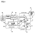
FIG. 1 is a configuration diagram of an elevator operation control device according to an embodiment of the present invention; -
FIG. 2 is a view schematically illustrating a data table used in the embodiment of the present invention; -
FIG. 3 is a waveform diagram illustrating a relationship between a shake of a building and contact of a long object according to the embodiment of the present invention; and -
FIG. 4 is a flowchart for explaining a simulation operation according to the embodiment of the present invention. - The elevator operation control method and operation control device according to the embodiment estimate the amount of shake (i.e. shaking or rocking motion) of a long object which moves accompanying lifting and lowering of a passenger cage by way of simulation based on the amount of shake of a building in which an elevator is installed and current position information of the passenger cage of the elevator. The elevator operation control method and operation control device control and operate the elevator according to the estimated amount of shake of the long object. The elevator operation control method and operation control device change every second a physical model of the simulation according to a position of the running passenger cage, and simulate in real time the amount of shake of the long object from a current amount of shake of the building and position information of the running passenger cage. The elevator operation control method and operation control device perform a control operation matching this threshold when the amount of shake of the long object calculated by this simulation exceeds a threshold determined in advance.
- The embodiment of the present invention will be described in detail below using the attached drawings as an example.
- In
FIG. 1 , anelevator 11 is installed in a hoistway in a building which is not illustrated. In a machine room at a top part of this building, ahoist 12 which is a driving source of theelevator 11 is installed. Amain rope 13 is wound around thishoist 12, and a passenger cage 14 is attached to one end of the main rope and acounter weight 15 is attached to the other end. Further, a compensatingsheave 16 is disposed at a bottom part of the hoistway, a compensatingrope 17 is wound around this compensatingsheave 16 and, at both end portions of the compensating rope, lower portions of the passenger cage 14 and thecounter weight 15 are attached. - In addition to these, a governor rope which is not illustrated and is vertically stretched in the hoistway and a tail cord (transmission cable) which connects between the passenger cage 14 and a
control device 22 described below are provided, and move accompanying lifting and lowering of the passenger cage 14. Hereinafter, themain rope 13, compensatingrope 17, and the governor rope and the tail cord which are not illustrated are collectively referred to as a long object. - The
control device 22 controls an operation of theelevator 11, and is generally provided in the machine room at the top part of the building. Thiscontrol device 22 is configured with a computer on which a CPU, a ROM and a RAM are mounted. Functionally, this control device has the simulatingunit 23 and thecontrol unit 24 which are realized by the CPU,andamemoryunit 25 which is configured by, for example, the ROM and the RAM. - The simulating
unit 23 has a function of, when a building is shaken by an earthquake or a strong wind, estimating a shake of a long object accompanying this shake. Thecontrol unit 24 has, for example, a function of executing a series of processing related to operation control of theelevator 11 such as driving control of thehoist 12, and controlling an operation of the passenger cage 14 based on a shake estimation result of the long object obtained by the simulatingunit 23. In addition to this, thecontrol unit 24 performs alarm processing to a disaster-prevention center 27 or analarming device 28 in theelevator 11 based on the simulation result of the simulatingunit 23. - The
memory unit 25 stores various items of data and programs which are not illustrated and are required to control an operation of the elevator. Further, a data table 29 which is described below and is used to estimate a shake of a long object is configured. - A shake of the building is measured by a
shake sensor 30 which is provided in, for example, the machine room at the top part of the building. For thisshake sensor 30, for example, an acceleration sensor is used. - The above simulating
unit 23 estimates the amount of shake of the long object which moves accompanying lifting and lowering of the passenger cage 14 based on the amount of shake of the building in which theelevator 11 is installed and current position information of the passenger cage 14 of theelevator 11. That is, the simulatingunit 23 changes every second a physical model of simulation according to a position of the running passenger cage 14 and the amount of shake of a building, and simulates in real time the amount of shake of the long object from a current amount of shake of the building and position information of the running passenger cage 14. - Meanwhile, various methods of estimating the amount of shake of a long object caused by a shake of a building have been proposed. The applicant of this application proposed a rope shake simulator (an analysis program which operates on a PC), and estimates the amount of shake by performing analysis using this simulator. When receiving an input of given limited input conditions, that is, a predetermined building input wave (time-series shake data of a building or Sin wave data) and a passenger cage position (fixed value), this simulator obtains time-series data of a shake of a rope as an output. This simulator is very useful for the above predetermined building input wave and a fixed cage position, and, in experiments of manybuildings, matches between analysis values and actual amounts of shake of a rope are checked.
- Although the simulating
unit 23 according to the present embodiment is appropriated from the above simulator, the above simulator performs simulation using a position of the passenger cage as a fixed value. However, upon an operation of the elevator, the position of the passenger cage changes every second and a natural period (frequency) of a long object also changes accompanying a change of this position of the passenger cage, and therefore a simulator which assumes a fixed position of the passenger cage is not applied as is. - A relationship between a shake of a long object and a position of a passenger cage will be described below. The long object collectively refers to the
main rope 13, and thecompensating rope 17, the governor rope and the tail cord as described above, themain rope 13 and thecompensating rope 17 which are illustrated herein will be described. - The
main rope 13 is partitioned into a portion (a portion A inFIG. 1 ) attached to the passenger cage 14 side and a portion (a portion C inFIG. 1 ) attached to thecounter weight 15 side. Thecompensating rope 17 is partitioned into a portion (a portion B inFIG. 1 ) attached to the passenger cage 14 side and a portion (a portion D inFIG. 1 ) attached to thecounter weight 15 side. - The lengths of the portions A, C, B and D of these
long objects main rope 13 is focused upon and the passenger cage 14 is at the bottom floor, while the portion A of the main rope 13 (simply referred to as a rope A below) of the passenger cage 14 side is the longest, the portion C of the main rope 13 (simply referred to as a rope C below) of thecounter weight 15 side is the shortest. This relationship reverses in case of thecompensating rope 17, and, when the passenger cage 14 is at the bottom floor, while the portion B of the compensating rope 17 (simply referred to as a rope B below) of the passenger cage 14 side is the shortest, the portion D of the compensating rope 17 (simply referred to as a rope D below) of thecounter weight 15 side is the longest. - Meanwhile, a relationship between a position of the passenger cage 14 and the amount of shake of a long object when the building is shaken at a certain magnitude will be described.
- In case of the
main rope 13, the rope A of the passenger cage 14 side is shaken the most when the passenger cage 14 is near the position of the bottom floor, and is shaken little at a position in a range from a middle floor to the vicinity of the top floor. Meanwhile, the rope C of thecounter weight 15 side is shaken the most when the passenger cage 14 is near the top floor, and is shaken little at a position in a range from the middle floor to the vicinity of the bottom floor. - In case of the compensating
rope 17, the rope B of the passenger cage 14 side is shaken the most when the passenger cage 14 is on a floor which is a little higher than the middle floor, and is shaken little at a position in a range from the middle floor to the bottom side. Meanwhile, the rope D of thecounter weight 15 side is shaken the most when the passenger cage 14 is on a floor which is a littler lower than the middle floor, and is shaken little from the middle floor to the top side. - Thus, when the lengths of the ropes A, C, B and D which are long objects change, the natural frequencies of these ropes also change, and the amounts of shake of the long objects caused by a shake of the building also change. The above lengths of the ropes A, C, B and D are determined according to the position of the passenger cage 14. The position of the passenger cage 14 is calculated based on the number of times of rotation and the rotation direction of the hoist 12, and the position of the passenger cage 14 is inputted to the
control device 22 as a cage position signal at all times. - According to the present embodiment, the simulating
unit 23 receives an input of the amount of shake of the building from theshake sensor 30, and receives an input of cage position information of thepassenger cage 24 which changes every second, from the hoist 12 side described above. Further, using these input values, the current amount of shake of the long object is calculated in real time. A long-period shake of the building is known to occur as a Sin wave which includes the primary natural frequency f [Hz] and the amplitude A [mm] of the building, and a peak of a shake of the building which shakes the long object comes once in 1/2 f[s]. Consequently, by continuing estimate calculation of the amount of shake of the long object once in 1/2 f[s], it is possible to learn the amount of shake of the long object in real time. - The
control unit 24 causes an adequate elevator control operation matching the amount of shake of the long object when a shake calculated value of the long object calculated by the simulatingunit 23 exceeds a certain threshold. For example, a plurality of levels of thresholds is set, and an alarm is set off to the disaster-prevention center 27 or thealarming device 28 of theelevator 11 according to the amount of shake of the long object or the elevator is operated at a speed which causes a little influence of a shake of the long object or is controlled to stop. - An example of this control operation will be described. The amount of shake of the long object in case that the passenger cage 14 at the current position arrives at a destination floor upon the current amount of shake of the building is predicted using position information of the destination floor. When the amount of shake which is a predicted value is expected to exceed the threshold, a destination floor is changed to a floor at which, for example, the predicted value of the amount of shake of the long object is expected not to exceed the threshold without going to this destination floor.
- Thus, when a building is shaken, the position of the passenger cage which changes every second is inputted while the elevator is operated and the amount of shake of the long object is calculated from the amount of shake of the building without first stopping the operation of the elevator as in the conventional technique, so that it is possible to accurately estimate in real time the amount of shake of the long object corresponding to a shake at a current point of time. Further, a control operation is performed according to this result, so that it is possible to dramatically reduce a stop frequency of the elevator compared to the conventional technique and improve operation service of the elevator.
- Next, a method of creating the data tables 29 in advance and calculating the amount of shake of a long object caused by a shake of a building using data of these data tables 29 will be described as the simulation method of the simulating
unit 23. - In this case, for all passenger cage positions corresponding to a plurality of height positions (for example, floors) set in advance in the building in which the
elevator 11 is installed, the simulatingunit 23 calculates in advance a time-series change of the amount of shake of the long object corresponding to the amount of shake of the building by means of the above simulator. Further, the data table 29 obtained by converting this result into a table is created and is stored in thememory unit 25. A physical model of simulation of the simulatingunit 23 selects the corresponding data table 29 from the current amount of shake of the building and the passenger cage position, and estimates in real time the amount of shake of the long object using information of this data table 29. - Meanwhile, fluctuation elements upon creation of the data tables 29 are as follows.
- Shake of Building ..... N patterns of data in predetermined ranges X0 to XNgal obtained by setting an output of the building shake sensor (acceleration sensor) 30 by a predetermined value Xgal.
- Elapsed time ..... Y/T patterns of data in predetermined time ranges 0 to Y seconds is used by a predetermined time (about half (1/2f) = T [s] of a building period f[Hz]).
- Machine ..... When paths are different between machines, the number of machines of different paths is used as machine data.
- Type of long object ... Each of the ropes A, C, B and D is type data of a long object. When a governor rope and a tail cord are included as long objects, the same data is used for these rope and cord. However, only the main rope and the compensating rope (ropes A, C, B and D) will be described below.
- Cage position ..... A floor position of a building is used as described above in the present embodiment, and each floor is cage position data.
-
Fig. 2 illustrates a configuration example of the data table 29 configured using these fluctuation elements. A table 291 inFIG. 2 represents a time-series (by T[s]) change of the amount of shake of the rope A of themachines passenger cage position 1F to 44F (there are 44 floors) upon the building shake X1gal. That is, allpassenger cage positions 1F to 44Fset in advance are indicated on the vertical axis and the elapsed times 0 to Y seconds by T seconds are indicated on the horizontal axis, and, at a crossing portion of these axes, the amount of shake of the rope (a numerical value is omitted) calculated for the rope A in advance by the above simulator is set. - N patterns (291 to 29N) of the data tables 29 of this rope A are created in the predetermined ranges X0 to XNgal by the predetermined value Xgal per shake of the building. Further, data tables equivalent to these N patterns of the data tables 29 are created per above machine and per type of the long object.
- Next, an example of a method of estimating in real time the amount of shake of a long object using these data tables 29 will be described. A basic theory of estimating in real time the amount of shake of a long object (also referred to as the amount of shake of a rope below) is based on the following equation.


- In above equations (1) and (2),
- DR0: Default Amount of Shake of Rope (mm)
- DT: Amount of Shake of Building (mm)
- DR: Amount of Shake of Rope (mm) after shaking at DT
- n: Machine
- Lt: Cage Position
- R: Target Rope (Ropes A, B, C, D)
- ΔDR: Increase/Decrease Amount of Shake of Rope
-
FIG. 3 illustrates a relationship between a building shake waveform α and a rope shake waveform β. InFIG. 3 , in a state of the default amount of shake of rope (the current amount of shake of rope) DR0, the amount of shake of a rope DR after a shake of a building shake DT is applied next is represented by above equation (1). - Meanwhile, a sign and a value of ΔDR change according to the machine n/the cage position Lt/the target rope R/the default amount of shake of a rope DR0/the building shake DT. Growths of shakes of a rope under all assumable conditions are calculated by the above simulator, and are converted into tables and functions as illustrated in
FIG. 2 . Further, by extracting ΔDR from the table upon cross-reference to current information, the amount of shake of a rope is estimated in real time. - Next, an example of specific process of calculating the amount of shake of rope using the data tables 29 will be described in association with operation steps in a flowchart illustrated in
FIG. 4 . Calculation Process 0: Default Setting - Before a calculation routine is started, each current rope shake default value DR0 is set to an arbitrary value Z0[mm] (step 401).
- A cage position closest in the table 29 is selected from current cage position information (step 402). For example, the cage position of the
machine 1 is 6F. - A current building shake peak value (X1gal) is inputted from an output of the current building shake sensor 30 (step 403).
- A table corresponding to each rope is calculated according to the conditions of the calculation processes 1 and 2 (step 404).
- The building shake is X1gal, and the table 291 in
FIG. 2 is calculated for the rope A of theabove machine 1. - A value Z0 of a current default amount of shake of a rope DR0 set in advance, and a rope shake maximum value DRMAX at a corresponding cage position are compared and determined (step 405).
- A maximum value among values a61~a6Y of the amounts of shake of a rope DR at 6F of the cage position in the table 291 in
FIG. 2 is DRMAX and a value Z0 of DR0 are compared, and, when DR0 < DRMAX holds as a result, a shaking mode is determined. The rope A of themachine 1 is in the shaking mode. In addition, when determination in thisstep 405 is No, the rope transitions to a damping mode. Computation in the damping mode is not directly relevant to the present invention, and therefore will not be described. - The increase amount of shake of a rope ΔDR after T seconds upon the default amount of shake of a rope DR0 of each rope is extracted from a table (step 406).
- From the values a61~a6Y of the amount of shake of a rope DR at 6F of the cage position in the table 291, a value closest to the value Z0 of the default amount of shake of the rope DR0 is selected for the rope A of the
machine 1. Meanwhile, a value a62 is a value closest to the value Z0. Further, a value ad1 of a difference between this value a62 and the value a63 after T seconds is extracted from the table 291 as the increase amount of shake of a rope ΔDR after T seconds. - From the value Z0 of the default amount of shake of a rope DR0 set in advance and the value ad1 of the increase amount of shake of a rope ΔDR extracted from the table 291, the amount of shake of a rope DR after T seconds is calculated according to above equation (1) for the rope A of the machine 1 (step 407). That is, a value obtained by adding the value ad1 of the increase amount of shake of a rope ΔDR to the value Z0 of the default amount of shake of a rope DR0 is calculated as the amount of shake of a rope DR (Z1) after T seconds from the present.
- The above calculation processes 1 to 6 are repeated every T second until a time Y passes (
steps 408 and 409), and the amount of shake of a rope DR at each point of time is calculated. The calculated amount of shake of a rope DR is compared with a threshold set in advance and whether or not a control operation needs to be performed is determined. - When the calculation processes 1 to 6 are repeated every T second, a value of the amount of shake of a rope DR (Z1 in the above example) calculated upon previous computation is used as a value of the current default amount of shake of the rope DR0 (step 410). Further, when the position of the passenger cage is different from a previous position after T seconds pass, computation is performed using information of another cage position on the table 291 (step 402). Furthermore, when the amount of shake of the building changes after T seconds pass, a table corresponding to the current amount of shake is used (
steps 403 and 404). When, for example, the amount of shake of the building changes to X3gal, computation is performed using data of the table (293) corresponding to the amount of shake. - Thus, the simulating
unit 23 changes every second a physical model of simulation using data of the data table 29, so that it is possible to accurately calculate in real time the amount of shake of a long object from the current amount of shake of a building and passenger cage position information without stopping an operation of the elevator. - Further, a control operation of the elevator is performed based on the amount of shake of the long object calculated in real time, so that it is possible to effectivelyprevent a catch due to a shake of the long object. Furthermore, although, when a building is shaken, an elevator is first stopped at all times according to the conventional technique, the amount of shake of a long object can be estimated in a state where the operation of the elevator is continued, so that it is possible to dramatically reduce a stop frequency of the elevator and improve operation service according to the present embodiment.
- In addition, a rope shake data table per load capacity of the passenger cage 14 may be prepared in advance as a configuration of the data table 29, and the amount of shake of a rope may be calculated additionally using a cage load capacity of a real machine. By so doing, precision to estimate the amount of shake of a rope further improves.
- According to the embodiment, a simulation model is changed every second according to, for example, a passenger cage position upon an operation of an elevator, and the amount of shake of a long object caused by a shake of a building is estimated, so that it is possible to accurately learn the current amount of shake of a long object caused by the shake of the building. Consequently, it is possible to reduce a stop frequency of the elevator and improve operation service of the elevator compared to a conventional technique.
- While certain embodiments have been described, those embodiments have been presented by way of example only, and are not intended to limit the scope of the invention. Indeed, the novel embodiments described herein may be embodied in a variety of other forms; furthermore, various omissions, substitutions and changes in the form of the embodiments described herein may be made without departing from the invention. The accompanying claims and their equivalents are intended to cover such forms or modifications as would fall within the scope of the invention.
- It is explicitly stated that all features disclosed in the description and/or the claims are intended to be disclosed separately and independently from each other for the purpose of original disclosure as well as for the purpose of restricting the claimed invention independent of the composition of the features in the embodiments and/or the claims. It is explicitly stated that all value ranges or indications of groups of entities disclose every possible intermediate value or intermediate entity for the purpose of original disclosure as well as for the purpose of restricting the claimed invention, in particular as limits of value ranges.
Claims (6)
- An elevator operation control method of estimating an amount of shake of a long object (13, 17) which moves accompanying lifting and lowering of a passenger cage (14) by way of simulation based on an amount of shake of a building in which an elevator (11) is installed and current position information of the passenger cage of the elevator, and controlling and operating the elevator according to the estimated amount of shake of the long object, the elevator operation control method comprising:changing every second a physical model of the simulation according to the position of the running passenger cage (14), and simulating in real time the amount of shake of the long object (13, 17) from the current amount of shake of the building and position information of the running passenger cage; and when the amount of shake of the long object (13, 17) calculated by the simulation exceeds a threshold determined in advance, performing a control operation matching this threshold.
- The elevator operation control method according to claim 1, wherein: according to the simulation, the amount of shake of the long object (13, 17) in case that the passenger cage (14) which is at a current position upon the current amount of shake of the building arrives at a destination floor is predicted using position information of the destination floor; and when the amount of shake of the long object (13, 17) at the destination floor is expected to exceed the threshold, the destination floor is changed.
- The elevator operation control method according to claim 1 or 2, wherein: a time-series change of the amount of shake of the long object (13, 17) corresponding to the amount of shake of the building at all positions of the passenger cage corresponding to a plurality of height positions of the building set in advance is calculated in advance, and a result is converted into a table (29); and a physical model of the simulation estimates in real time the amount of shake of the long object (13, 17) using corresponding information which is converted into the table (29) from the current amount of shake of the building and the position of the passenger cage (14).
- An elevator operation control device (22) characterised by comprising:a simulating unit (23) adapted to estimate an amount of shake of a long object (13, 17) which moves accompanying lifting and lowering of a passenger cage (14) based on an amount of shake of a building in which an elevator (11) is installed and current position information of the passenger cage of the elevator; anda control unit (24) adapted to control and operate the elevator (11) according to the amount of shake of the long object (13, 17) estimated by the simulating unit (23), wherein:the simulating unit (23) is adapted to change every second a physical model of the simulation according to the position of the running passenger cage (14), and simulate in real time the amount of shake of the long object (13, 17) from the current amount of shake of the building and position information of the running passenger cage (14); andthe control unit, when the amount of shake of the long object (13, 17) calculated by the simulating unit (23) exceeds a threshold determined in advance, is adapted to perform a control operation matching this threshold.
- The elevator operation control device according to claim 4, wherein: the simulating unit (23) comprises a function of predicting the amount of shake of the long object (13, 17) in case that the passenger cage (14) which is at a current position upon the current amount of shake of the building arrives at a destination floor, using position information of the destination floor; and the control unit (24) comprises a function of, when the amount of shake of the long object (13, 17) upon arrival at the destination floor is expected to exceed the threshold, changing the destination floor.
- The elevator operation control device according to claim 4 or 5, wherein: the simulating unit (23) is adapted to calculate in advance a time-series change of the amount of shake of the long object (13, 17) corresponding to the amount of shake of the building at all positions of the passenger cage corresponding to a plurality of height positions of the building set in advance, and convert the result into a table (29); and a physical model of the simulation estimates in real time the amount of shake of the long object (13, 17) using corresponding information which is converted into the table (29) from the current amount of shake of the building and the position of the passenger cage (14).
Applications Claiming Priority (1)
| Application Number | Priority Date | Filing Date | Title |
|---|---|---|---|
| JP2012250879A JP5605860B2 (en) | 2012-11-15 | 2012-11-15 | Elevator operation control method and operation control apparatus |
Publications (3)
| Publication Number | Publication Date |
|---|---|
| EP2733103A2 EP2733103A2 (en) | 2014-05-21 |
| EP2733103A3 EP2733103A3 (en) | 2014-10-08 |
| EP2733103B1 true EP2733103B1 (en) | 2016-01-13 |
Family
ID=49518875
Family Applications (1)
| Application Number | Title | Priority Date | Filing Date |
|---|---|---|---|
| EP13192015.9A Active EP2733103B1 (en) | 2012-11-15 | 2013-11-07 | Elevator operation control method and operation control device |
Country Status (3)
| Country | Link |
|---|---|
| US (1) | US9415972B2 (en) |
| EP (1) | EP2733103B1 (en) |
| JP (1) | JP5605860B2 (en) |
Cited By (3)
| Publication number | Priority date | Publication date | Assignee | Title |
|---|---|---|---|---|
| CN110422710A (en) * | 2019-07-26 | 2019-11-08 | 美的置业集团有限公司 | A kind of intelligent sound manipulation elevator control method, device, medium and terminal device |
| EP3848320A1 (en) | 2020-01-07 | 2021-07-14 | KONE Corporation | Method for operating an elevator |
| EP3848319A1 (en) | 2020-01-07 | 2021-07-14 | KONE Corporation | Method for operating an elevator |
Families Citing this family (6)
| Publication number | Priority date | Publication date | Assignee | Title |
|---|---|---|---|---|
| WO2013184085A1 (en) * | 2012-06-04 | 2013-12-12 | Otis Elevator Company | Elevator rope sway mitigation |
| CN106573753B (en) * | 2014-07-31 | 2019-09-10 | 奥的斯电梯公司 | Building rocks operating system |
| CN111573474B (en) * | 2019-02-19 | 2023-02-28 | 富士达株式会社 | Long-strip article swing detection device |
| JP7379798B2 (en) * | 2019-10-11 | 2023-11-15 | 株式会社竹中工務店 | Earthquake simulation device, earthquake simulation control program |
| CN112723215A (en) * | 2020-12-24 | 2021-04-30 | 刘启俊 | Winch stall self-locking device for preventing stall from hurting people in winch using process |
| JP7409540B1 (en) | 2023-03-17 | 2024-01-09 | フジテック株式会社 | Elevator device control method and elevator device |
Family Cites Families (20)
| Publication number | Priority date | Publication date | Assignee | Title |
|---|---|---|---|---|
| US3792759A (en) * | 1972-12-22 | 1974-02-19 | Westinghouse Electric Corp | Elevator system |
| JPH0631142B2 (en) * | 1986-03-27 | 1994-04-27 | 三菱電機株式会社 | Elevator earthquake operation device |
| JP2002032701A (en) * | 2000-07-14 | 2002-01-31 | Kajima Corp | Method and device for analyzing performance of building |
| US7793763B2 (en) * | 2003-11-14 | 2010-09-14 | University Of Maryland, Baltimore County | System and method for damping vibrations in elevator cables |
| WO2006100750A1 (en) * | 2005-03-22 | 2006-09-28 | Mitsubishi Denki Kabushiki Kaisha | Car sway detector for elevator |
| JP4618101B2 (en) * | 2005-11-08 | 2011-01-26 | 鹿島建設株式会社 | Elevator control operation device |
| JP5255180B2 (en) * | 2005-12-05 | 2013-08-07 | 日本オーチス・エレベータ株式会社 | Elevator earthquake control operation system and elevator earthquake control operation method |
| JP5014623B2 (en) * | 2005-12-12 | 2012-08-29 | 三菱電機株式会社 | Seismic control operation system for elevator and earthquake control operation method for elevator |
| WO2007086098A1 (en) * | 2006-01-24 | 2007-08-02 | Mitsubishi Denki Kabushiki Kaisha | Remote informing system for elevator |
| JP4399438B2 (en) * | 2006-06-16 | 2010-01-13 | 株式会社日立製作所 | Elevator equipment |
| JP2008044701A (en) * | 2006-08-11 | 2008-02-28 | Toshiba Elevator Co Ltd | Earthquake emergency operation device for elevator |
| US7926620B2 (en) * | 2006-08-29 | 2011-04-19 | Mitsubishi Electric Corporation | Elevator control apparatus and control method |
| JP4607078B2 (en) * | 2006-09-20 | 2011-01-05 | 三菱電機株式会社 | Elevator rope roll detection device and elevator control operation device |
| KR101229023B1 (en) * | 2008-03-17 | 2013-02-01 | 오티스 엘리베이터 컴파니 | Elevator dispatching control for sway mitigation |
| JP2010052924A (en) * | 2008-08-29 | 2010-03-11 | Toshiba Elevator Co Ltd | Control device of elevator |
| JP2010070298A (en) * | 2008-09-17 | 2010-04-02 | Mitsubishi Electric Corp | Emergency operation device for elevator |
| FI123182B (en) * | 2012-02-16 | 2012-12-14 | Kone Corp | Method for controlling the lift and lift |
| US9045313B2 (en) * | 2012-04-13 | 2015-06-02 | Mitsubishi Electric Research Laboratories, Inc. | Elevator rope sway estimation |
| US10192411B2 (en) * | 2012-12-13 | 2019-01-29 | Oneevent Technologies, Inc. | Sensor-based monitoring system |
| EP2960677A4 (en) * | 2013-02-25 | 2016-10-12 | Tokai Ryokaku Tetsudo Kk | Earthquake prediction device |
-
2012
- 2012-11-15 JP JP2012250879A patent/JP5605860B2/en active Active
-
2013
- 2013-11-07 EP EP13192015.9A patent/EP2733103B1/en active Active
- 2013-11-08 US US14/075,720 patent/US9415972B2/en active Active
Cited By (5)
| Publication number | Priority date | Publication date | Assignee | Title |
|---|---|---|---|---|
| CN110422710A (en) * | 2019-07-26 | 2019-11-08 | 美的置业集团有限公司 | A kind of intelligent sound manipulation elevator control method, device, medium and terminal device |
| EP3848320A1 (en) | 2020-01-07 | 2021-07-14 | KONE Corporation | Method for operating an elevator |
| EP3848319A1 (en) | 2020-01-07 | 2021-07-14 | KONE Corporation | Method for operating an elevator |
| CN113148807A (en) * | 2020-01-07 | 2021-07-23 | 通力股份公司 | Method for operating an elevator |
| US11780705B2 (en) | 2020-01-07 | 2023-10-10 | Kone Corporation | Method for operating an elevator |
Also Published As
| Publication number | Publication date |
|---|---|
| US9415972B2 (en) | 2016-08-16 |
| JP5605860B2 (en) | 2014-10-15 |
| JP2014097871A (en) | 2014-05-29 |
| EP2733103A2 (en) | 2014-05-21 |
| US20140131141A1 (en) | 2014-05-15 |
| EP2733103A3 (en) | 2014-10-08 |
Similar Documents
| Publication | Publication Date | Title |
|---|---|---|
| EP2733103B1 (en) | Elevator operation control method and operation control device | |
| JP4618101B2 (en) | Elevator control operation device | |
| JP6049902B2 (en) | Elevator diagnostic equipment | |
| JP6521887B2 (en) | Elevator system, method for controlling operation of elevator system and non-transitory computer readable medium | |
| CN103803378A (en) | Method and system for controlling operation of elevator systems | |
| JP5704700B2 (en) | Elevator control device and sensor | |
| JP2009166939A (en) | Elevator emergency operation device | |
| JP2016197013A (en) | Building damage intensity estimating system and method | |
| JP6614165B2 (en) | Threshold decision method, threshold decision device, and elevator control system | |
| CN107514344A (en) | Tower hoisting method of wind generating set and vortex-induced vibration monitoring system | |
| JP2010052924A (en) | Control device of elevator | |
| JP6104409B2 (en) | Control parameter detection method, elevator group management simulation method, control parameter detection device, and elevator group management simulation device | |
| JP5495684B2 (en) | Elevator earthquake damage prediction device | |
| JP2006225104A (en) | Elevator control device | |
| JP2009051610A (en) | Rope lateral swinging detecting device of elevator | |
| KR101901352B1 (en) | Predicting System For Seismic Observation | |
| JP2008133105A (en) | Device for detecting rope-sway of elevator | |
| JP2011051739A (en) | Control device of elevator | |
| JP5535441B2 (en) | Elevator control operation device | |
| US20210285513A1 (en) | Method and device for preventing impact vibration of lift system | |
| JP2003112862A (en) | Elevator vibration monitoring device | |
| JP5473375B2 (en) | Earthquake monitoring control system | |
| JP2008081290A (en) | Rope rolling detector for elevator | |
| JP6740324B2 (en) | Car weighing method and device | |
| JP5562196B2 (en) | Elevator control command device, elevator device, and elevator system |
Legal Events
| Date | Code | Title | Description |
|---|---|---|---|
| PUAI | Public reference made under article 153(3) epc to a published international application that has entered the european phase |
Free format text: ORIGINAL CODE: 0009012 |
|
| 17P | Request for examination filed |
Effective date: 20131107 |
|
| AK | Designated contracting states |
Kind code of ref document: A2 Designated state(s): AL AT BE BG CH CY CZ DE DK EE ES FI FR GB GR HR HU IE IS IT LI LT LU LV MC MK MT NL NO PL PT RO RS SE SI SK SM TR |
|
| AX | Request for extension of the european patent |
Extension state: BA ME |
|
| PUAL | Search report despatched |
Free format text: ORIGINAL CODE: 0009013 |
|
| AK | Designated contracting states |
Kind code of ref document: A3 Designated state(s): AL AT BE BG CH CY CZ DE DK EE ES FI FR GB GR HR HU IE IS IT LI LT LU LV MC MK MT NL NO PL PT RO RS SE SI SK SM TR |
|
| AX | Request for extension of the european patent |
Extension state: BA ME |
|
| RIC1 | Information provided on ipc code assigned before grant |
Ipc: B66B 1/28 20060101AFI20140829BHEP Ipc: B66B 7/06 20060101ALN20140829BHEP |
|
| RBV | Designated contracting states (corrected) |
Designated state(s): AL AT BE BG CH CY CZ DE DK EE ES FI FR GB GR HR HU IE IS IT LI LT LU LV MC MK MT NL NO PL PT RO RS SE SI SK SM TR |
|
| GRAP | Despatch of communication of intention to grant a patent |
Free format text: ORIGINAL CODE: EPIDOSNIGR1 |
|
| RIC1 | Information provided on ipc code assigned before grant |
Ipc: B66B 7/06 20060101ALN20150701BHEP Ipc: B66B 1/28 20060101AFI20150701BHEP |
|
| RIC1 | Information provided on ipc code assigned before grant |
Ipc: B66B 1/28 20060101AFI20150713BHEP Ipc: B66B 7/06 20060101ALN20150713BHEP |
|
| INTG | Intention to grant announced |
Effective date: 20150730 |
|
| GRAS | Grant fee paid |
Free format text: ORIGINAL CODE: EPIDOSNIGR3 |
|
| GRAA | (expected) grant |
Free format text: ORIGINAL CODE: 0009210 |
|
| RIN1 | Information on inventor provided before grant (corrected) |
Inventor name: TANAKA, KAZUHIRO |
|
| AK | Designated contracting states |
Kind code of ref document: B1 Designated state(s): AL AT BE BG CH CY CZ DE DK EE ES FI FR GB GR HR HU IE IS IT LI LT LU LV MC MK MT NL NO PL PT RO RS SE SI SK SM TR |
|
| REG | Reference to a national code |
Ref country code: GB Ref legal event code: FG4D |
|
| REG | Reference to a national code |
Ref country code: CH Ref legal event code: EP |
|
| REG | Reference to a national code |
Ref country code: IE Ref legal event code: FG4D |
|
| REG | Reference to a national code |
Ref country code: AT Ref legal event code: REF Ref document number: 770361 Country of ref document: AT Kind code of ref document: T Effective date: 20160215 Ref country code: CH Ref legal event code: NV Representative=s name: E. BLUM AND CO. AG PATENT- UND MARKENANWAELTE , CH |
|
| REG | Reference to a national code |
Ref country code: DE Ref legal event code: R096 Ref document number: 602013004610 Country of ref document: DE |
|
| REG | Reference to a national code |
Ref country code: LT Ref legal event code: MG4D |
|
| REG | Reference to a national code |
Ref country code: NL Ref legal event code: MP Effective date: 20160113 |
|
| REG | Reference to a national code |
Ref country code: AT Ref legal event code: MK05 Ref document number: 770361 Country of ref document: AT Kind code of ref document: T Effective date: 20160113 |
|
| PG25 | Lapsed in a contracting state [announced via postgrant information from national office to epo] |
Ref country code: NL Free format text: LAPSE BECAUSE OF FAILURE TO SUBMIT A TRANSLATION OF THE DESCRIPTION OR TO PAY THE FEE WITHIN THE PRESCRIBED TIME-LIMIT Effective date: 20160113 |
|
| PG25 | Lapsed in a contracting state [announced via postgrant information from national office to epo] |
Ref country code: GR Free format text: LAPSE BECAUSE OF FAILURE TO SUBMIT A TRANSLATION OF THE DESCRIPTION OR TO PAY THE FEE WITHIN THE PRESCRIBED TIME-LIMIT Effective date: 20160414 Ref country code: ES Free format text: LAPSE BECAUSE OF FAILURE TO SUBMIT A TRANSLATION OF THE DESCRIPTION OR TO PAY THE FEE WITHIN THE PRESCRIBED TIME-LIMIT Effective date: 20160113 Ref country code: HR Free format text: LAPSE BECAUSE OF FAILURE TO SUBMIT A TRANSLATION OF THE DESCRIPTION OR TO PAY THE FEE WITHIN THE PRESCRIBED TIME-LIMIT Effective date: 20160113 Ref country code: IT Free format text: LAPSE BECAUSE OF FAILURE TO SUBMIT A TRANSLATION OF THE DESCRIPTION OR TO PAY THE FEE WITHIN THE PRESCRIBED TIME-LIMIT Effective date: 20160113 Ref country code: NO Free format text: LAPSE BECAUSE OF FAILURE TO SUBMIT A TRANSLATION OF THE DESCRIPTION OR TO PAY THE FEE WITHIN THE PRESCRIBED TIME-LIMIT Effective date: 20160413 |
|
| PG25 | Lapsed in a contracting state [announced via postgrant information from national office to epo] |
Ref country code: PL Free format text: LAPSE BECAUSE OF FAILURE TO SUBMIT A TRANSLATION OF THE DESCRIPTION OR TO PAY THE FEE WITHIN THE PRESCRIBED TIME-LIMIT Effective date: 20160113 Ref country code: LV Free format text: LAPSE BECAUSE OF FAILURE TO SUBMIT A TRANSLATION OF THE DESCRIPTION OR TO PAY THE FEE WITHIN THE PRESCRIBED TIME-LIMIT Effective date: 20160113 Ref country code: AT Free format text: LAPSE BECAUSE OF FAILURE TO SUBMIT A TRANSLATION OF THE DESCRIPTION OR TO PAY THE FEE WITHIN THE PRESCRIBED TIME-LIMIT Effective date: 20160113 Ref country code: LT Free format text: LAPSE BECAUSE OF FAILURE TO SUBMIT A TRANSLATION OF THE DESCRIPTION OR TO PAY THE FEE WITHIN THE PRESCRIBED TIME-LIMIT Effective date: 20160113 Ref country code: SE Free format text: LAPSE BECAUSE OF FAILURE TO SUBMIT A TRANSLATION OF THE DESCRIPTION OR TO PAY THE FEE WITHIN THE PRESCRIBED TIME-LIMIT Effective date: 20160113 Ref country code: RS Free format text: LAPSE BECAUSE OF FAILURE TO SUBMIT A TRANSLATION OF THE DESCRIPTION OR TO PAY THE FEE WITHIN THE PRESCRIBED TIME-LIMIT Effective date: 20160113 Ref country code: PT Free format text: LAPSE BECAUSE OF FAILURE TO SUBMIT A TRANSLATION OF THE DESCRIPTION OR TO PAY THE FEE WITHIN THE PRESCRIBED TIME-LIMIT Effective date: 20160513 Ref country code: IS Free format text: LAPSE BECAUSE OF FAILURE TO SUBMIT A TRANSLATION OF THE DESCRIPTION OR TO PAY THE FEE WITHIN THE PRESCRIBED TIME-LIMIT Effective date: 20160513 |
|
| REG | Reference to a national code |
Ref country code: DE Ref legal event code: R097 Ref document number: 602013004610 Country of ref document: DE |
|
| PG25 | Lapsed in a contracting state [announced via postgrant information from national office to epo] |
Ref country code: EE Free format text: LAPSE BECAUSE OF FAILURE TO SUBMIT A TRANSLATION OF THE DESCRIPTION OR TO PAY THE FEE WITHIN THE PRESCRIBED TIME-LIMIT Effective date: 20160113 Ref country code: DK Free format text: LAPSE BECAUSE OF FAILURE TO SUBMIT A TRANSLATION OF THE DESCRIPTION OR TO PAY THE FEE WITHIN THE PRESCRIBED TIME-LIMIT Effective date: 20160113 |
|
| PLBE | No opposition filed within time limit |
Free format text: ORIGINAL CODE: 0009261 |
|
| STAA | Information on the status of an ep patent application or granted ep patent |
Free format text: STATUS: NO OPPOSITION FILED WITHIN TIME LIMIT |
|
| PG25 | Lapsed in a contracting state [announced via postgrant information from national office to epo] |
Ref country code: SM Free format text: LAPSE BECAUSE OF FAILURE TO SUBMIT A TRANSLATION OF THE DESCRIPTION OR TO PAY THE FEE WITHIN THE PRESCRIBED TIME-LIMIT Effective date: 20160113 Ref country code: SK Free format text: LAPSE BECAUSE OF FAILURE TO SUBMIT A TRANSLATION OF THE DESCRIPTION OR TO PAY THE FEE WITHIN THE PRESCRIBED TIME-LIMIT Effective date: 20160113 Ref country code: CZ Free format text: LAPSE BECAUSE OF FAILURE TO SUBMIT A TRANSLATION OF THE DESCRIPTION OR TO PAY THE FEE WITHIN THE PRESCRIBED TIME-LIMIT Effective date: 20160113 Ref country code: RO Free format text: LAPSE BECAUSE OF FAILURE TO SUBMIT A TRANSLATION OF THE DESCRIPTION OR TO PAY THE FEE WITHIN THE PRESCRIBED TIME-LIMIT Effective date: 20160113 |
|
| 26N | No opposition filed |
Effective date: 20161014 |
|
| PG25 | Lapsed in a contracting state [announced via postgrant information from national office to epo] |
Ref country code: BE Free format text: LAPSE BECAUSE OF FAILURE TO SUBMIT A TRANSLATION OF THE DESCRIPTION OR TO PAY THE FEE WITHIN THE PRESCRIBED TIME-LIMIT Effective date: 20160113 |
|
| PG25 | Lapsed in a contracting state [announced via postgrant information from national office to epo] |
Ref country code: BG Free format text: LAPSE BECAUSE OF FAILURE TO SUBMIT A TRANSLATION OF THE DESCRIPTION OR TO PAY THE FEE WITHIN THE PRESCRIBED TIME-LIMIT Effective date: 20160413 Ref country code: SI Free format text: LAPSE BECAUSE OF FAILURE TO SUBMIT A TRANSLATION OF THE DESCRIPTION OR TO PAY THE FEE WITHIN THE PRESCRIBED TIME-LIMIT Effective date: 20160113 |
|
| REG | Reference to a national code |
Ref country code: IE Ref legal event code: MM4A |
|
| REG | Reference to a national code |
Ref country code: FR Ref legal event code: ST Effective date: 20170731 |
|
| PG25 | Lapsed in a contracting state [announced via postgrant information from national office to epo] |
Ref country code: LU Free format text: LAPSE BECAUSE OF NON-PAYMENT OF DUE FEES Effective date: 20161130 |
|
| PG25 | Lapsed in a contracting state [announced via postgrant information from national office to epo] |
Ref country code: FR Free format text: LAPSE BECAUSE OF NON-PAYMENT OF DUE FEES Effective date: 20161130 |
|
| PG25 | Lapsed in a contracting state [announced via postgrant information from national office to epo] |
Ref country code: IE Free format text: LAPSE BECAUSE OF NON-PAYMENT OF DUE FEES Effective date: 20161107 |
|
| PG25 | Lapsed in a contracting state [announced via postgrant information from national office to epo] |
Ref country code: HU Free format text: LAPSE BECAUSE OF FAILURE TO SUBMIT A TRANSLATION OF THE DESCRIPTION OR TO PAY THE FEE WITHIN THE PRESCRIBED TIME-LIMIT; INVALID AB INITIO Effective date: 20131107 Ref country code: CY Free format text: LAPSE BECAUSE OF FAILURE TO SUBMIT A TRANSLATION OF THE DESCRIPTION OR TO PAY THE FEE WITHIN THE PRESCRIBED TIME-LIMIT Effective date: 20160113 |
|
| PG25 | Lapsed in a contracting state [announced via postgrant information from national office to epo] |
Ref country code: MK Free format text: LAPSE BECAUSE OF FAILURE TO SUBMIT A TRANSLATION OF THE DESCRIPTION OR TO PAY THE FEE WITHIN THE PRESCRIBED TIME-LIMIT Effective date: 20160113 Ref country code: MC Free format text: LAPSE BECAUSE OF FAILURE TO SUBMIT A TRANSLATION OF THE DESCRIPTION OR TO PAY THE FEE WITHIN THE PRESCRIBED TIME-LIMIT Effective date: 20160113 |
|
| GBPC | Gb: european patent ceased through non-payment of renewal fee |
Effective date: 20171107 |
|
| PG25 | Lapsed in a contracting state [announced via postgrant information from national office to epo] |
Ref country code: MT Free format text: LAPSE BECAUSE OF NON-PAYMENT OF DUE FEES Effective date: 20161107 |
|
| PG25 | Lapsed in a contracting state [announced via postgrant information from national office to epo] |
Ref country code: TR Free format text: LAPSE BECAUSE OF FAILURE TO SUBMIT A TRANSLATION OF THE DESCRIPTION OR TO PAY THE FEE WITHIN THE PRESCRIBED TIME-LIMIT Effective date: 20160113 Ref country code: AL Free format text: LAPSE BECAUSE OF FAILURE TO SUBMIT A TRANSLATION OF THE DESCRIPTION OR TO PAY THE FEE WITHIN THE PRESCRIBED TIME-LIMIT Effective date: 20160113 |
|
| PG25 | Lapsed in a contracting state [announced via postgrant information from national office to epo] |
Ref country code: GB Free format text: LAPSE BECAUSE OF NON-PAYMENT OF DUE FEES Effective date: 20171107 |
|
| PGFP | Annual fee paid to national office [announced via postgrant information from national office to epo] |
Ref country code: CH Payment date: 20221201 Year of fee payment: 10 |
|
| PGFP | Annual fee paid to national office [announced via postgrant information from national office to epo] |
Ref country code: FI Payment date: 20231116 Year of fee payment: 11 Ref country code: DE Payment date: 20230912 Year of fee payment: 11 |