EP2731666B1 - Retractable luer lock fittings - Google Patents
Retractable luer lock fittings Download PDFInfo
- Publication number
- EP2731666B1 EP2731666B1 EP12825476.0A EP12825476A EP2731666B1 EP 2731666 B1 EP2731666 B1 EP 2731666B1 EP 12825476 A EP12825476 A EP 12825476A EP 2731666 B1 EP2731666 B1 EP 2731666B1
- Authority
- EP
- European Patent Office
- Prior art keywords
- male
- tubing fitting
- female
- collar
- internal bore
- Prior art date
- Legal status (The legal status is an assumption and is not a legal conclusion. Google has not performed a legal analysis and makes no representation as to the accuracy of the status listed.)
- Active
Links
- 230000014759 maintenance of location Effects 0.000 claims description 30
- 238000003780 insertion Methods 0.000 claims description 5
- 230000037431 insertion Effects 0.000 claims description 5
- 230000000717 retained effect Effects 0.000 description 9
- 238000004891 communication Methods 0.000 description 7
- 238000001356 surgical procedure Methods 0.000 description 5
- 230000002452 interceptive effect Effects 0.000 description 3
- 238000000034 method Methods 0.000 description 2
- 230000004075 alteration Effects 0.000 description 1
- 239000012530 fluid Substances 0.000 description 1
- 238000012986 modification Methods 0.000 description 1
- 230000004048 modification Effects 0.000 description 1
- 230000037361 pathway Effects 0.000 description 1
- 230000008569 process Effects 0.000 description 1
- 230000001737 promoting effect Effects 0.000 description 1
Images


Classifications
-
- A—HUMAN NECESSITIES
- A61—MEDICAL OR VETERINARY SCIENCE; HYGIENE
- A61M—DEVICES FOR INTRODUCING MEDIA INTO, OR ONTO, THE BODY; DEVICES FOR TRANSDUCING BODY MEDIA OR FOR TAKING MEDIA FROM THE BODY; DEVICES FOR PRODUCING OR ENDING SLEEP OR STUPOR
- A61M39/00—Tubes, tube connectors, tube couplings, valves, access sites or the like, specially adapted for medical use
- A61M39/10—Tube connectors; Tube couplings
- A61M39/1011—Locking means for securing connection; Additional tamper safeties
-
- A—HUMAN NECESSITIES
- A61—MEDICAL OR VETERINARY SCIENCE; HYGIENE
- A61M—DEVICES FOR INTRODUCING MEDIA INTO, OR ONTO, THE BODY; DEVICES FOR TRANSDUCING BODY MEDIA OR FOR TAKING MEDIA FROM THE BODY; DEVICES FOR PRODUCING OR ENDING SLEEP OR STUPOR
- A61M39/00—Tubes, tube connectors, tube couplings, valves, access sites or the like, specially adapted for medical use
- A61M39/10—Tube connectors; Tube couplings
- A61M2039/1033—Swivel nut connectors, e.g. threaded connectors, bayonet-connectors
Definitions
- the present disclosure relates generally to a retractable luer lock fitting configured to couple tubings to a surgical instrument used in ophthalmic surgeries.
- a variety of surgical systems are used in ophthalmic surgery.
- such systems may include a surgical console, accessories (e.g. footswitch, reusable handpieces), and various consumables.
- the consumables typically include tubing sets that connect to the console and provide a pathway from the console in the non-sterile field to a surgical instrument or other device that is used in and remains in the sterile field.
- a tubing fitting is typically used to fluidly couple tubing from the console to a surgical device.
- EP 1 563 863 A1 US 5,620,427 A , WO 84/00595 A1 , US 2003/184090 A1 .
- the present invention provides a retractable luer lock system in accordance with claims which follow.
- the present disclosure is directed to a system.
- the system has a male tubing fitting extending along a longitudinal axis.
- the male tubing fitting has a first internal bore and an end portion including a male plug.
- the system also has a female tubing fitting that has a second internal bore configured to receive the male plug.
- the system has a collar disposed about the male tubing fitting and positioned to slide freely along the longitudinal axis from a first position to a second position. In the first position the male and female tubing fittings are unlocked with respect to each other such that the male plug is removably insertable into the second internal bore of the female tubing fitting. In the second position the male and female fittings are locked with respect to each other such that the male plug is prevented from being removed from the second internal bore of the female tubing fitting.
- the present disclosure is directed to a system.
- the system has a male tubing fitting having an exterior surface extending along a longitudinal axis and a tapered end portion.
- the male tubing fitting includes a first internal bore.
- the system also has a female tubing fitting that has a second internal bore configured to receive the tapered end portion.
- the female tubing fitting has an exterior surface that includes a projection.
- the system has a collar disposed about the exterior surface of the male tubing and rotatable about the longitudinal axis with respect to the male tubing fitting.
- the collar includes a threaded internal bore that has an interior surface that includes a thread pattern defining a space configured to removably receive the projection of the female tubing fitting. Rotation of the collar about the longitudinal axis relative to the male tubing fitting when the projection is positioned within the space sealingly engages and locks the first internal bore of the male tubing fitting with the second internal bore of the female tubing fitting.
- the present disclosure is directed to a system.
- the system has a male tubing fitting that has an exterior surface extending along a longitudinal axis and includes a retention member.
- the male tubing further includes a first internal bore and a tapered end portion.
- the system has a female tubing fitting that has a second internal bore configured to receive the tapered end portion.
- the system has a collar disposed about the exterior surface of the male tubing fitting and selectively retained by the retention member at a first position along the longitudinal axis.
- the collar includes an elastically deformable portion that deforms in order to position the collar beyond the selective retainment of the retention member to a second position along the longitudinal axis.
- the present disclosure relates generally to the field of ophthalmic surgery, and more particularly to a retractable luer lock fitting configured to couple tubings to a surgical instrument used in ophthalmic surgeries.
- a retractable luer lock fitting configured to couple tubings to a surgical instrument used in ophthalmic surgeries.
- Fig. 1 is an illustration of an exploded view of an exemplary retractable luer lock system 100.
- retractable luer lock system 100 includes female tubing fitting 102, or female luer lock.
- retractable luer lock system 100 includes male tubing fitting 104, or male luer fitting.
- retractable luer lock system 100 includes retractable locking collar 106.
- retractable locking collar 106 is configured to retract, translate, slide, move, and/or rotate about male tubing fitting 104. As such, retractable locking collar 106 can move axially with respect to male tubing fitting 104 to effectively lock and unlock the male tubing fitting 104 and female tubing fitting 102 together.
- female tubing fitting 102 is shown having a generally tubular shape extending from a proximal end 108 to a distal end 110.
- An internal bore 112 extends through female tubing fitting 102.
- Proximal opening 114 is in communication with the internal bore 112 at the proximal end 108 and distal opening 116 is in communication with the internal bore 112 at the distal end 110.
- internal bore 112 is defined by interior surface 118 which continuously tapers from the proximal end 108 to the distal end 110.
- internal bore 112 has a luer taper.
- female tubing fitting 102 includes projections 120, or wings extending from external surface 122.
- female tubing fitting 102 has a pair of opposing projections 120 that are positioned on opposing sides of the proximal end 108.
- Projections 120 extend substantially transverse to longitudinal axis L 1 of the female tubing fitting 102.
- each projection 102 extends in opposing directions from longitudinal axis L 1 .
- female tubing fitting 102 has one or more than two projections 120.
- projections 120 assist in locking the female tubing fitting 102 to the male tubing fitting 104.
- male tubing fitting 104 extends from a proximal end 124 to a distal end 126.
- the proximal end 124 includes flanges 128 and distal end 126 forms a male plug 130, or tapered distal end portion.
- flanges 128 provide a traction or gripping surface for a user of system 100 to use while connecting and/or disconnecting female and male tubing fittings 102 and 104.
- male plug 130 has a luer taper and is sized and shaped to be received within internal bore 112 of female tubing fitting 102.
- flanges 128 allow a user to grip male tubing fitting 104 during insertion of or removal of male plug 130 into or from internal bore 112 of female tubing fitting 102. As such, flanges 128 assist in ease of connection and disconnection between female and male tubing fittings 102 and 104.
- proximal end 146 of retractable locking collar 106 includes relief portions 164, or apertures, or slits.
- exterior surface 166 of retractable locking collar 106 is interrupted by relief portions 164.
- Relief portions 164 extend from the exterior surface 166 through to the interior surface 156 defining internal bore 150.
- relief portions 164 increase the flexibility and/or elasticity of proximal end 146.
- proximal end 146 is elastically deformable because of relief portions 164.
- Proximal end 146 of retractable locking collar 106 also includes a tapered lip 168 or flange extending into internal bore 150.
- tapered lip 168 is adjacent to and surrounds proximal opening 152.
- tapered lip 168 is interrupted by relief portions 164.
- tapered lip 168 forms an non-continuous annular lip around proximal opening 152.
- tapered lip 168 interfaces with proximal and distal retention members 140 and 142 to retain and/or hold the retractable locking collar in a predetermined position along exterior surface 144 of male tubing fitting 104.
- retractable locking collar 106 has a plurality of ridges 174 extending about exterior surface 164.
- ridges 174 provide a gripping surface that enables a user to hold or grasp on to while positioning retractable collar 106 about male tubing fitting 104.
- ridges 174 provide a surface to hold onto while retracting, translating, sliding, moving and/or rotating retractable locking collar 106 about male tubing fitting 104.
- Fig. 4 shows the retractable locking collar 106 being retained by proximal retention member 140.
- retractable locking collar In this position, retractable locking collar is considered in a retracted position, or first position.
- tapered lip 168 of retractable locking collar 106 is positioned between base 170 of flanges 128 and proximal retention member 140 while in the retracted position.
- the proximal retention member 140 abuts the tapered lip 168 of the retracted locking collar thereby selectively retaining the locking collar from moving along exterior surface 144 towards the male plug 130.
- male plug 130 of male tubing fitting 104 is more easily accessible because the locking collar is selectively retained and/or prevented from sliding towards the plug thereby keeping the collar from interfering with use of the plug.
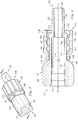
- Fig. 6 shows a cross-sectional view of luer lock system 100 in an unlocked configuration.
- retractable locking collar 106 is selectively retained by the proximal retention member 140 in the retracted position.
- tapered lip 168 abuts the proximal retention member 140 thereby selectively preventing the locking collar from moving along exterior surface 144 towards the male plug 130.
- male plug 130 of male tubing fitting 104 is more easily accessible because the locking collar is selectively retained and/or prevented from sliding towards the plug thereby keeping the collar from interfering with use of the plug.
- male plug 130 has been inserted into internal bore 112 of female tubing fitting 102 through proximal opening 114.
- retractable locking collar 106 because retractable locking collar 106 is in the retracted position, the locking collar is selectively retained and/or prevented from sliding towards the plug thereby keeping the collar from interfering with insertion of the plug into the female tubing fitting 102.
- retractable locking collar 106 does not lock the female and male tubing fittings 102 and 104 together when in the retracted position.
- male plug 130 is removably insertable within internal bore 112 of female tubing fitting 102.
- male plug 130 can be inserted into and removed from internal bore 112 of female tubing fitting 102 when the retractable locking collar 106 is in the retracted position. Accordingly, in the unlocked configuration retractable locking collar 106 is retracted and not locking the female and male tubing fittings 102 and 104 together.
- flanges 128 further assist during connection of male tubing fitting 104 and female tubing fitting 102.
- flanges 128 of male tubing fitting 104 enable a user to more easily grip male tubing fitting 104 during insertion of male plug 130 into internal bore 112.
- flanges 128 provide a grip surface that allows a user to twist, push, pull, and/or the like on male tubing fitting 104 during connection of female and male tubing fittings 102 and 104. Accordingly, in the unlocked configuration flanges 128 help position the male tubing fitting 104 within the female tubing fitting 102.
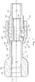
- Fig. 7 shows a cross-sectional view of luer lock system 100 in a locked configuration. From the unlocked configuration shown in Fig. 6 , retractable locking collar 106 has moved along exterior surface 144 and is now retained by distal retention member 142 in an non-retracted position, or second position. As shown, tapered lip 168 of retractable locking collar 106 is positioned between distal retention member 142 and ridge 172 of male plug 130 while in the non-retracted position.
- retractable locking collar 106 has been moved in a first direction along longitudinal axis L 2 towards male plug 130.
- the proximal end 146 has increased flexibility because of relief portions 164, the proximal end 146 can deform or flex outwardly away from exterior surface 144 when passing over and beyond proximal and distal retention member 140 and 142, respectively, as it moves along exterior surface 144 towards male plug 130.
- the tapered lip 168 flexes outwardly away from exterior surface 144 when the lip abuts against proximal and distal retention members 140 and 142, respectively.
- tapered lip 168 is able to pass over the proximal and distal retention members 140 and 142, respectively, and move along exterior surface 144 towards male plug 130 into the non-retracted configuration. Accordingly, in the non-retracted configuration tapered lip 168 abuts against distal retention member 142 and thereby selectively retains the locking collar from moving along exterior surface 144 in an opposing second direction along longitudinal axis L 2 towards the flanges 128.
- retractable locking collar 106 While the retractable locking collar 106 is in the non-retracted position male plug 130 is prevented from being removed from internal bore 112 of female tubing fitting 102. Accordingly, in the locked configuration the retractable locking collar 106 locks the female and male tubing fittings 102 and 104 together to thereby sealingly engage the internal bores of the respective tubings.
- retractable locking collar 106 is configured such that it is rotated about longitudinal axis L 2 in another direction (e.g. counter-clockwise) to sealingly engage and lock male tubing fitting 104 and female tubing fitting 102 together.
- threads 158 and 160 of retractable locking collar 106 are oriented such that counter-clockwise rotation of retractable locking collar 106 about longitudinal axis L 2 sealingly engages and locks male tubing fitting 104 and female tubing fitting 102 together.
- retractable locking collar 106 rotates about longitudinal axis L 2 in the first direction relative to male tubing fitting 104 to lock the female and male tubing fittings 102 and 104.
- female and male tubing fittings 102 and 104 do not necessarily need to be rotated with respect to each other.
- the locking of male and female tubings together is simplified due to the lack of twisting and/or rotation required as result of retractable locking collar 106 locking the tubings together.
- retractable luer lock system 100 can return to the unlocked configuration shown in Fig. 6 from the locked configuration shown in Fig. 7 .
- male tubing fitting 104 and female tubing fitting 102 may be unlocked from each other by rotating retractable locking collar 106 about longitudinal axis L 2 in a second direction (e.g. counterclockwise) relative to male tubing fitting 104.
- retractable locking collar 106 is moved along exterior surface 144 such that tapered lip 168 is selectively retained by proximal retention member 140 in the retracted configuration (See Fig. 6 ).
- the proximal end 146 can flex or deform outwardly away from exterior surface 144 (i.e. longitudinal axis L 2 ) when passing over or beyond distal and proximal retention members 142 and 140, respectively, as it moves along exterior surface 144 in a second direction along longitudinal axis L 2 towards flanges 128.
- exterior surface 144 i.e. longitudinal axis L 2
- the tapered lip 168 deforms or flexes outwardly away from exterior surface 144 when the lip abuts against distal and proximal retention members 142 and 140, respectively.
- the tapered lip 168 is able to pass beyond the selective retainment of distal and proximal retention members 142 and 140, respectively, and move along exterior surface 144 towards flanges 128 until the retractable locking collar assumes the retracted position.
- retractable luer lock system 100 in which a healthcare provider uses retractable luer lock system 100 to fluidly couple a surgical instrument to a surgical console.
- Female tubing fitting 102 is fluidly coupled at distal end 110 to the surgical instrument.
- internal bore 112 of female tubing fitting 102 is in fluid communication with the surgical instrument.
- the surgical instrument is then fluidly coupled to the surgical console.
- male plug 130 in inserted into internal bore 112 of female tubing fitting 102.
- the retractable locking collar 106 is in the retracted position during the insertion of male plug 130 into internal bore 122.
- retractable locking collar 106 is slid along exterior surface 144 of male tubing fitting 104 from the retracted position to the non-retracted position.
- the spaces 162 of retractable locking collar 106 are aligned with respect to projections 120 of female tubing fitting 102.
- retractable luer lock system 100 provides a retractable luer lock than enables male and female tubing fittings to be sealingly engaged with respect to each other.
- male tubing fitting 104 and female tubing fitting 102 may be unlocked by rotating retractable locking collar 106 in a second direction (e.g. counter-clockwise) about longitudinal axis L 2 of male tubing fitting 104 that opposes the first direction. Moreover, once unlocked the retractable locking collar is slid along the exterior surface to the retracted position. In the retracted position, the retractable locking collar is no longer locking the female and male tubing fittings 102 and 104 together. As such, flanges 128 are used to provide a gripping surface to assist in pulling, twisting, and/or physically removing the male tubing fitting 104 from the female tubing fitting 102. In other words, with the retractable locking collar 106 in the retracted position, male plug 130 can be removed from internal bore 112 thereby physically disconnecting the female and male tubing fittings 102 and 104 from each other.
- a second direction e.g. counter-clockwise
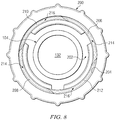
- Fig. 8 shows an end view of an alternative retractable locking collar 200 according to one aspect of the present disclosure.
- Retractable locking collar 200 is similar to retractable locking collar 106.
- locking collar 200 can be used in place of locking collar 106 in retractable luer lock system 100.
- only the differences with respect to locking collar 200 are described below.
- locking collar 200 has internal bore 202 which is defined by interior surface 204.
- Interior surface 204 includes threads 206, 208, 210, and 212, or sloping ramps.
- Threads 206, 208, 210, and 212 form a quad helix thread pattern extending circumferentially along interior surface 204 within internal bore 202.
- threads 206 and 208 form a pair of opposing threads that are sloped in opposing directions with respect to each other.
- threads 210 and 212 form a pair of opposing threads that are sloped in opposing directions with respect to each other.
- retractable locking collar 200 has four spaces for receiving projections 120. Therefore, when projections 120 are placed in spaces 214 and/or 216 and locking collar 200 is rotated male tubing fitting 104 and female tubing fitting 102 are locked together. Accordingly, retractable locking collar 200 provides an alternative locking collar having additional spaces and threading relative to retractable locking collar 106.
- female tubing fitting 102 can include more than the two projections 120 shown in Fig. 1 when using retractable locking collar 200.
- the female tubing fitting 102 can included two pair of opposing projections 120. As such, there are projections 120 for each of the spaces 214 and 216.
- projections 120 there is no implied limitation on the number of and/or configuration of projections 120 as long as the projections 120 align with and are sized to be positioned within the spaces of the retractable locking collar. Similarly, there is no implied limitation on the number of and/or configuration of the threading in the retractable locking collars disclosed herein as long as the space formed by the threading is compatible with a given female tubing fitting.
Description
- The present disclosure relates generally to a retractable luer lock fitting configured to couple tubings to a surgical instrument used in ophthalmic surgeries.
- A variety of surgical systems are used in ophthalmic surgery. For example, such systems may include a surgical console, accessories (e.g. footswitch, reusable handpieces), and various consumables. The consumables typically include tubing sets that connect to the console and provide a pathway from the console in the non-sterile field to a surgical instrument or other device that is used in and remains in the sterile field. A tubing fitting is typically used to fluidly couple tubing from the console to a surgical device.
- Luer fittings are used extensively on medical devices such as syringes, needles, catheters, and tubing sets. Two types are common: luer slip fittings and luer lock fittings. Both types consist of a male fitting and a female fitting. Luer slip fittings are sealably engaged by a friction fit between the male and female luer surfaces. Luer lock fittings are sealably engaged with an additional lock feature on the male and female luer surfaces. More specifically, the external female surface includes a pair of opposed flanges proximate its opening. The male fitting includes a collar that receives the female fitting and has a single internal spiral thread that rotationally engages the opposed flanges to sealably engage with respect to each other.
- As ophthalmic surgery continues to increase in sophistication and complexity, the need remains for new tubing fittings that will prevent the accidental misconnection of a standard luer slip fitting and/or a standard luer lock fitting. Additionally, there remains a need to simplify the connection between male and female tubing. Furthermore, there remains a need for such a connection to be backwards compatible with existing accessories with no locking features.
- The systems, devices, and methods disclosed herein overcome at least one of the shortcomings in the prior art.
- The present state of the art is represented by
EP 1 563 863 A1 ,US 5,620,427 A ,WO 84/00595 A1 US 2003/184090 A1 . - The present invention provides a retractable luer lock system in accordance with claims which follow. In one exemplary aspect, the present disclosure is directed to a system. The system has a male tubing fitting extending along a longitudinal axis. The male tubing fitting has a first internal bore and an end portion including a male plug. The system also has a female tubing fitting that has a second internal bore configured to receive the male plug. Also, the system has a collar disposed about the male tubing fitting and positioned to slide freely along the longitudinal axis from a first position to a second position. In the first position the male and female tubing fittings are unlocked with respect to each other such that the male plug is removably insertable into the second internal bore of the female tubing fitting. In the second position the male and female fittings are locked with respect to each other such that the male plug is prevented from being removed from the second internal bore of the female tubing fitting.
- In one exemplary aspect, the present disclosure is directed to a system. The system has a male tubing fitting having an exterior surface extending along a longitudinal axis and a tapered end portion. The male tubing fitting includes a first internal bore. The system also has a female tubing fitting that has a second internal bore configured to receive the tapered end portion. The female tubing fitting has an exterior surface that includes a projection. Also, the system has a collar disposed about the exterior surface of the male tubing and rotatable about the longitudinal axis with respect to the male tubing fitting. The collar includes a threaded internal bore that has an interior surface that includes a thread pattern defining a space configured to removably receive the projection of the female tubing fitting. Rotation of the collar about the longitudinal axis relative to the male tubing fitting when the projection is positioned within the space sealingly engages and locks the first internal bore of the male tubing fitting with the second internal bore of the female tubing fitting.
- In one exemplary aspect, the present disclosure is directed to a system. The system has a male tubing fitting that has an exterior surface extending along a longitudinal axis and includes a retention member. The male tubing further includes a first internal bore and a tapered end portion. Also, the system has a female tubing fitting that has a second internal bore configured to receive the tapered end portion. Additionally, the system has a collar disposed about the exterior surface of the male tubing fitting and selectively retained by the retention member at a first position along the longitudinal axis. The collar includes an elastically deformable portion that deforms in order to position the collar beyond the selective retainment of the retention member to a second position along the longitudinal axis. In the first position the male and female tubing fittings are unlocked with respect to each other such that the tapered end portion is removably insertable into the second internal bore of the female tubing fitting. In the second position the male and female fittings are locked with respect to each other such that the tapered end portion is prevented from being removed from the second internal bore of the female tubing fitting.
- These and other aspects, forms, objects, features, and benefits of the present disclosure will become apparent from the following detailed drawings and description. configured to receive the tapered end portion. Additionally, the system has a collar disposed about the exterior surface of the male tubing fitting and selectively retained by the retention member at a first position along the longitudinal axis. The collar includes an elastically deformable portion that deforms in order to position the collar beyond the selective retainment of the retention member to a second position along the longitudinal axis. In the first position the male and female tubing fittings are unlocked with respect to each other such that the tapered end portion is removably insertable into the second internal bore of the female tubing fitting. In the second position the male and female fittings are locked with respect to each other such that the tapered end portion is prevented from being removed from the second internal bore of the female tubing fitting.
- These and other aspects, forms, objects, features, and benefits of the present disclosure will become apparent from the following detailed drawings and description.
- The accompanying drawings, which are incorporated in and constitute a part of the specification, illustrate embodiments of the present disclosure. Together with a general description of the present disclosure given above, and the detailed description given below, the drawings serve to exemplify the embodiments of the present disclosure.
-
Fig. 1 is an illustration of an exploded view of an exemplary retractable luer lock system according to one aspect of the present disclosure. -
Fig. 2 is an illustration of a cross-sectional view of a female tubing fitting used in the retractable luer lock system shown inFig. 1 according to one aspect of the present disclosure. -
Fig. 3 is an illustration of a perspective view of a male tubing fitting including a retractable locking collar used in the retractable luer lock system shown inFig. 1 according to one aspect of the present disclosure. -
Fig. 4 is an illustration of a cross-sectional view of the male tubing fitting including the retractable locking collar shown inFig. 3 according to one aspect of the present disclosure. -
Fig. 5 is an illustration of an end view of the male tubing fitting including the retractable locking collar shown inFig. 3 according to one aspect of the present disclosure. -
Fig. 6 is an illustration of a cross-sectional view of the exemplary retractable luer lock system ofFig. 1 in an unlocked configuration according to one aspect of the present disclosure. -
Fig. 7 is an illustration of a cross-sectional view of the exemplary retractable luer lock system ofFig. 1 in a locked configuration according to one aspect of the present disclosure. -
Fig. 8 is an illustration of an end view of the male tubing fitting ofFig. 3 including an alternative retractable locking collar according to one aspect of the present disclosure. - The present disclosure relates generally to the field of ophthalmic surgery, and more particularly to a retractable luer lock fitting configured to couple tubings to a surgical instrument used in ophthalmic surgeries. For the purposes of promoting an understanding of the principles of the present disclosure, reference will now be made to embodiments or examples illustrated in the drawings, and specific language will be used to describe these examples. It will nevertheless be understood that no limitation of the scope of the present disclosure is thereby intended. Any alteration and further modifications in the described embodiments, and any further applications of the principles of the present disclosure as described herein are contemplated as would normally occur to one skilled in the art to which the disclosure relates.
-
Fig. 1 is an illustration of an exploded view of an exemplary retractableluer lock system 100. As shown, retractableluer lock system 100 includes female tubing fitting 102, or female luer lock. Additionally, retractableluer lock system 100 includes male tubing fitting 104, or male luer fitting. Also, retractableluer lock system 100 includesretractable locking collar 106. As will be described in greater detail below,retractable locking collar 106 is configured to retract, translate, slide, move, and/or rotate about male tubing fitting 104. As such,retractable locking collar 106 can move axially with respect to male tubing fitting 104 to effectively lock and unlock the male tubing fitting 104 and female tubing fitting 102 together. - Referring to
Figs. 1 and 2 , female tubing fitting 102 is shown having a generally tubular shape extending from aproximal end 108 to adistal end 110. Aninternal bore 112 extends throughfemale tubing fitting 102.Proximal opening 114 is in communication with theinternal bore 112 at theproximal end 108 anddistal opening 116 is in communication with theinternal bore 112 at thedistal end 110. As shown,internal bore 112 is defined byinterior surface 118 which continuously tapers from theproximal end 108 to thedistal end 110. As such,internal bore 112 has a luer taper. - At the
proximal end 108, female tubing fitting 102 includesprojections 120, or wings extending fromexternal surface 122. Here, female tubing fitting 102 has a pair of opposingprojections 120 that are positioned on opposing sides of theproximal end 108.Projections 120 extend substantially transverse to longitudinal axis L1 of thefemale tubing fitting 102. Moreover, eachprojection 102 extends in opposing directions from longitudinal axis L1. Although shown as twoprojections 120, it is contemplated in other embodiments that female tubing fitting 102 has one or more than twoprojections 120. As will be described in greater detail below,projections 120 assist in locking the female tubing fitting 102 to the male tubing fitting 104. - Referring to
Figs. 1 ,3, and 4 , male tubing fitting 104 extends from aproximal end 124 to adistal end 126. Theproximal end 124 includesflanges 128 anddistal end 126 forms amale plug 130, or tapered distal end portion. In that regard,flanges 128 provide a traction or gripping surface for a user ofsystem 100 to use while connecting and/or disconnecting female andmale tubing fittings male plug 130 has a luer taper and is sized and shaped to be received withininternal bore 112 offemale tubing fitting 102. Thus,flanges 128 allow a user to grip male tubing fitting 104 during insertion of or removal ofmale plug 130 into or frominternal bore 112 offemale tubing fitting 102. As such,flanges 128 assist in ease of connection and disconnection between female andmale tubing fittings - As shown, male tubing fitting 104 includes an
internal bore 132 extending through male tubing fitting 104.Proximal opening 134 is in communication with theinternal bore 132 at theproximal end 124 anddistal opening 136 is in communication with theinternal bore 132 at thedistal end 126. Internal bore 132 is defined byinterior surface 138. In that regard,interior surface 138 tapers and/or steps down from theproximal end 124 to thedistal end 126. As such, the diameter ofinternal bore 132 at theproximal end 124 of male tubing fitting 104 is greater than the diameter of internal bore at thedistal end 126 of male tubing fitting 104. - As best shown in
Figs. 1 and4 , male tubing fitting 104 includes aproximal retention member 140, or annular nub, and adistal retention member 142, or annular nub. Proximal anddistal retention members exterior surface 144 of male tubing fitting 104. As will be described in greater detail below, proximal anddistal retention members retractable locking collar 106 in order to selectively retain and/or hold the locking collar in a desired position alongexterior surface 144 of male tubing fitting 104. - Referring to
Figs. 1 ,3, and 4 retractable locking collar 106 extends from aproximal end 146 to adistal end 148. As shown, aninternal bore 150 extends throughretractable locking collar 106.Proximal opening 152 is in communication with theinternal bore 150 at theproximal end 146 anddistal opening 154 is in communication with theinternal bore 150 at thedistal end 148. - Internal bore 150 is defined by
interior surface 156. As best shown inFig. 5 ,interior surface 156 includesthreads Threads internal bore 150. In that regard,threads interior surface 156. Additionally,threads spaces 162 configured for removably receivingprojections 120 offemale tubing fitting 102. As will be described in greater detail below, whenprojections 120 are placed inspaces 162 andretractable locking collar 106 is rotated in a first direction about male tubing fitting 104, male tubing fitting 104 is sealingly engaged with and locked intofemale tubing fitting 102. - As shown,
proximal end 146 ofretractable locking collar 106 includesrelief portions 164, or apertures, or slits. In that regard,exterior surface 166 ofretractable locking collar 106 is interrupted byrelief portions 164.Relief portions 164 extend from theexterior surface 166 through to theinterior surface 156 defininginternal bore 150. As such,relief portions 164 increase the flexibility and/or elasticity ofproximal end 146. Thus,proximal end 146 is elastically deformable because ofrelief portions 164. -
Proximal end 146 ofretractable locking collar 106 also includes atapered lip 168 or flange extending intointernal bore 150. In that regard, taperedlip 168 is adjacent to and surroundsproximal opening 152. Moreover, taperedlip 168 is interrupted byrelief portions 164. As such, taperedlip 168 forms an non-continuous annular lip aroundproximal opening 152. As described in greater detail below, taperedlip 168 interfaces with proximal anddistal retention members exterior surface 144 of male tubing fitting 104. - Referring to
Figs. 3 and 4 ,retractable locking collar 106 is disposed aroundexterior surface 144 of male tubing fitting 104.Retractable locking collar 106 is configured to be positioned alongexterior surface 144 of male tubing fitting 104. In that regard,retractable locking collar 106 can retract, translate, slide, move, and/or rotate freely about longitudinal axis L2 of male tubing fitting 104 as the collar moves alongexterior surface 144. For example,retractable locking collar 106 is positionable along any portion ofexterior surface 144 of male tubing fitting 104 from aboutbase 170 offlanges 128 toridge 172 ofmale plug 130. - As best seen in
Figs 1 and3 ,retractable locking collar 106 has a plurality ofridges 174 extending aboutexterior surface 164. In that regard,ridges 174 provide a gripping surface that enables a user to hold or grasp on to while positioningretractable collar 106 about male tubing fitting 104. Specifically,ridges 174 provide a surface to hold onto while retracting, translating, sliding, moving and/or rotatingretractable locking collar 106 about male tubing fitting 104. - Moreover,
Fig. 4 shows theretractable locking collar 106 being retained byproximal retention member 140. In this position, retractable locking collar is considered in a retracted position, or first position. As shown, taperedlip 168 ofretractable locking collar 106 is positioned betweenbase 170 offlanges 128 andproximal retention member 140 while in the retracted position. Additionally, in the retracted position theproximal retention member 140 abuts the taperedlip 168 of the retracted locking collar thereby selectively retaining the locking collar from moving alongexterior surface 144 towards themale plug 130. Thus, in the retracted position,male plug 130 of male tubing fitting 104 is more easily accessible because the locking collar is selectively retained and/or prevented from sliding towards the plug thereby keeping the collar from interfering with use of the plug. -
Fig. 6 shows a cross-sectional view ofluer lock system 100 in an unlocked configuration. In the unlocked configuration,retractable locking collar 106 is selectively retained by theproximal retention member 140 in the retracted position. In the retracted position, taperedlip 168 abuts theproximal retention member 140 thereby selectively preventing the locking collar from moving alongexterior surface 144 towards themale plug 130. Thus, in the retracted position,male plug 130 of male tubing fitting 104 is more easily accessible because the locking collar is selectively retained and/or prevented from sliding towards the plug thereby keeping the collar from interfering with use of the plug. - As shown in
Fig. 6 ,male plug 130 has been inserted intointernal bore 112 of female tubing fitting 102 throughproximal opening 114. As discussed above, becauseretractable locking collar 106 is in the retracted position, the locking collar is selectively retained and/or prevented from sliding towards the plug thereby keeping the collar from interfering with insertion of the plug into thefemale tubing fitting 102. Moreover,retractable locking collar 106 does not lock the female andmale tubing fittings retractable locking collar 106 is in the retracted positionmale plug 130 is removably insertable withininternal bore 112 offemale tubing fitting 102. In other words,male plug 130 can be inserted into and removed frominternal bore 112 of female tubing fitting 102 when theretractable locking collar 106 is in the retracted position. Accordingly, in the unlocked configurationretractable locking collar 106 is retracted and not locking the female andmale tubing fittings - Moreover,
flanges 128 further assist during connection of male tubing fitting 104 andfemale tubing fitting 102. In that regard,flanges 128 of male tubing fitting 104 enable a user to more easily grip male tubing fitting 104 during insertion ofmale plug 130 intointernal bore 112. For example,flanges 128 provide a grip surface that allows a user to twist, push, pull, and/or the like on male tubing fitting 104 during connection of female andmale tubing fittings unlocked configuration flanges 128 help position the male tubing fitting 104 within thefemale tubing fitting 102. -
Fig. 7 shows a cross-sectional view ofluer lock system 100 in a locked configuration. From the unlocked configuration shown inFig. 6 ,retractable locking collar 106 has moved alongexterior surface 144 and is now retained bydistal retention member 142 in an non-retracted position, or second position. As shown, taperedlip 168 ofretractable locking collar 106 is positioned betweendistal retention member 142 andridge 172 ofmale plug 130 while in the non-retracted position. - To achieve the non-retracted position,
retractable locking collar 106 has been moved in a first direction along longitudinal axis L2 towardsmale plug 130. In that regard, because theproximal end 146 has increased flexibility because ofrelief portions 164, theproximal end 146 can deform or flex outwardly away fromexterior surface 144 when passing over and beyond proximal anddistal retention member exterior surface 144 towardsmale plug 130. Specifically, when sufficient force is applied to locking collar in the direction ofmale plug 130, thetapered lip 168 flexes outwardly away fromexterior surface 144 when the lip abuts against proximal anddistal retention members tapered lip 168 is able to pass over the proximal anddistal retention members exterior surface 144 towardsmale plug 130 into the non-retracted configuration. Accordingly, in the non-retracted configuration taperedlip 168 abuts againstdistal retention member 142 and thereby selectively retains the locking collar from moving alongexterior surface 144 in an opposing second direction along longitudinal axis L2 towards theflanges 128. - Additionally,
Fig. 7 shows that male tubing fitting 104 is locked together to female tubing fitting 102 viaretractable locking collar 106. In that regard,retractable locking collar 106 has been aligned with respect toprojections 120 such that theprojections 120 are inserted intospaces 162 of the collar. Moreover,retractable locking collar 106 has been rotated about longitudinal axis L2 in a first direction (e.g. clockwise) to sealingly engage and lock male tubing fitting 104 and female tubing fitting 102 together. As such,internal bore 112 of the female tubing fitting andinternal bore 132 of the male tubing fitting 104 are fluidly coupled. Thus, while theretractable locking collar 106 is in the non-retracted positionmale plug 130 is prevented from being removed frominternal bore 112 offemale tubing fitting 102. Accordingly, in the locked configuration theretractable locking collar 106 locks the female andmale tubing fittings - It should be noted that in alternative embodiments,
retractable locking collar 106 is configured such that it is rotated about longitudinal axis L2 in another direction (e.g. counter-clockwise) to sealingly engage and lock male tubing fitting 104 and female tubing fitting 102 together. In such an alternative embodiment,threads retractable locking collar 106 are oriented such that counter-clockwise rotation ofretractable locking collar 106 about longitudinal axis L2 sealingly engages and locks male tubing fitting 104 and female tubing fitting 102 together. - Moreover, it should be noted that the locking of male tubing fitting 104 to
female tubing 102 viaretractable locking collar 106 can occur without rotation or twisting of the tubing fittings. As discussed above,retractable locking collar 106 rotates about longitudinal axis L2 in the first direction relative to male tubing fitting 104 to lock the female andmale tubing fittings male tubing fittings retractable locking collar 106 locking the tubings together. - Additionally, retractable
luer lock system 100 can return to the unlocked configuration shown inFig. 6 from the locked configuration shown inFig. 7 . In that regard, male tubing fitting 104 and female tubing fitting 102 may be unlocked from each other by rotatingretractable locking collar 106 about longitudinal axis L2 in a second direction (e.g. counterclockwise) relative to male tubing fitting 104. Moreover, from the locked configuration shown inFig. 7 ,retractable locking collar 106 is moved alongexterior surface 144 such thattapered lip 168 is selectively retained byproximal retention member 140 in the retracted configuration (SeeFig. 6 ). Because theproximal end 146 has increased flexibility as a result ofrelief portions 164, theproximal end 146 can flex or deform outwardly away from exterior surface 144 (i.e. longitudinal axis L2) when passing over or beyond distal andproximal retention members exterior surface 144 in a second direction along longitudinal axis L2 towardsflanges 128. Specifically, when sufficient force is applied toretractable locking collar 106 in the second direction towardsflanges 128, thetapered lip 168 deforms or flexes outwardly away fromexterior surface 144 when the lip abuts against distal andproximal retention members tapered lip 168 is able to pass beyond the selective retainment of distal andproximal retention members exterior surface 144 towardsflanges 128 until the retractable locking collar assumes the retracted position. - The following describes an exemplary use of retractable
luer lock system 100 in which a healthcare provider uses retractableluer lock system 100 to fluidly couple a surgical instrument to a surgical console. Female tubing fitting 102 is fluidly coupled atdistal end 110 to the surgical instrument. As such,internal bore 112 of female tubing fitting 102 is in fluid communication with the surgical instrument. - Male tubing fitting 104 is fluidly coupled to a first end of a piece of conventional plastic tubing. Specifically, the first end of the piece of tubing is inserted into
internal bore 132 of the male tubing fitting 104 throughproximal opening 134. The opposite end of the piece of plastic tubing is fluidly coupled to the surgical console. - The surgical instrument is then fluidly coupled to the surgical console. In that regard,
male plug 130 in inserted intointernal bore 112 offemale tubing fitting 102. More specifically, theretractable locking collar 106 is in the retracted position during the insertion ofmale plug 130 intointernal bore 122. Then,retractable locking collar 106 is slid alongexterior surface 144 of male tubing fitting 104 from the retracted position to the non-retracted position. Additionally, thespaces 162 ofretractable locking collar 106 are aligned with respect toprojections 120 offemale tubing fitting 102. Once the collar is in the non-retracted position and the projections are positioned withinspaces 162, theretractable locking collar 106 is rotated in a first direction (e.g. clockwise) about longitudinal axis L2 of male tubing fitting 104. Such rotation sealingly locks male tubing fitting 104 and female tubing fitting 102 together. Accordingly, retractableluer lock system 100 provides a retractable luer lock than enables male and female tubing fittings to be sealingly engaged with respect to each other. - Additionally, male tubing fitting 104 and female tubing fitting 102 may be unlocked by rotating
retractable locking collar 106 in a second direction (e.g. counter-clockwise) about longitudinal axis L2 of male tubing fitting 104 that opposes the first direction. Moreover, once unlocked the retractable locking collar is slid along the exterior surface to the retracted position. In the retracted position, the retractable locking collar is no longer locking the female andmale tubing fittings flanges 128 are used to provide a gripping surface to assist in pulling, twisting, and/or physically removing the male tubing fitting 104 from thefemale tubing fitting 102. In other words, with theretractable locking collar 106 in the retracted position,male plug 130 can be removed frominternal bore 112 thereby physically disconnecting the female andmale tubing fittings -
Fig. 8 shows an end view of an alternativeretractable locking collar 200 according to one aspect of the present disclosure.Retractable locking collar 200 is similar toretractable locking collar 106. Moreover, lockingcollar 200 can be used in place of lockingcollar 106 in retractableluer lock system 100. Moreover, for brevity purposes, only the differences with respect to lockingcollar 200 are described below. - As shown, locking
collar 200 hasinternal bore 202 which is defined byinterior surface 204.Interior surface 204 includesthreads Threads interior surface 204 withininternal bore 202. In that regard,threads threads - Additionally,
threads spaces 214 for receivingprojections 120 offemale tubing fitting 102. Furthermore,threads spaces 216 for receivingprojections 120 offemale tubing fitting 102. Thus,retractable locking collar 200 has four spaces for receivingprojections 120. Therefore, whenprojections 120 are placed inspaces 214 and/or 216 and lockingcollar 200 is rotated male tubing fitting 104 and female tubing fitting 102 are locked together. Accordingly,retractable locking collar 200 provides an alternative locking collar having additional spaces and threading relative toretractable locking collar 106. - Moreover, it is contemptible that female tubing fitting 102 can include more than the two
projections 120 shown inFig. 1 when usingretractable locking collar 200. For example, in alternative embodiments the female tubing fitting 102 can included two pair of opposingprojections 120. As such, there areprojections 120 for each of thespaces - Additionally, there is no implied limitation on the number of and/or configuration of
projections 120 as long as theprojections 120 align with and are sized to be positioned within the spaces of the retractable locking collar. Similarly, there is no implied limitation on the number of and/or configuration of the threading in the retractable locking collars disclosed herein as long as the space formed by the threading is compatible with a given female tubing fitting.
Claims (4)
- A retractable luer lock system (100) comprising:a male tubing fitting (104) extending along a longitudinal axis and having a first internal bore (132) and an end portion including a male plug (130), and wherein the male tubing fitting comprises a plurality of flanges (128) at a proximal end thereof;a female tubing fitting (102) with an exterior surface (122) having a second internal bore (112) configured to receive the male plug (130); anda collar (106) disposed about the male tubing fitting and positioned to slide freely along the longitudinal axis from a first retracted position to a second locked position, wherein in the first retracted position the male and female tubing fittings are unlocked with respect to each other such that the male plug (130) is removably insertable into the second internal bore (112) of the female tubing fitting, and in the second locked position the male and female fittings are locked with respect to each other such that the male plug is prevented from being removed from the second internal bore of the female tubing fitting, characterized in that the collar (106) includes an elastically deformable portion (146) that deforms in order to slidably position the collar along the longitudinal axis from the first retracted position to the second locked position,wherein the elastically deformable portion includes a tapered lip (168) that deforms outwardly away from the longitudinal axis,wherein the male tubing fitting (104) includes a proximal retention member (140) on an exterior surface (144) thereof that is adapted to interface with the tapered lip (168) to selectively retain the collar in the first retracted position,wherein the elastically deformable portion (146) includes slits (164) that interrupt the tapered lip thereby allowing the tapered lip to deform outwardly from the longitudinal axis to slide the collar beyond the selective retainment of the proximal retention member (140), andwherein the tapered lip (168) is able to pass beyond the selective retainment of the proximal retention member (140), and move along the exterior surface (144) towards the second locked position; andwherein the collar (106) is rotatable about the longitudinal axis with respect to the male tubing fitting (104), such that the collar (106) does not lock the female and male tubing fittings (102,104) together when in the first retracted position.
- The system of claim 1, wherein the collar (106) includes a third internal bore (150) such that the male tubing fitting is disposed through the third internal bore, the third internal bore having a thread pattern (158,160) that defines a space (162).
- The system of claim 2, wherein the exterior surface (122) of the female tubing fitting (102) includes a projection (120) for alignment and insertion into the thread pattern space (162) before the collar is rotated to the second position for sealingly engaging and locking the first internal bore of the male tubing fitting with the second internal bore of the female tubing fitting.
- The system of claim 1, wherein the exterior surface of the male tubing fitting includes a distal retention member (142), the distal retention member selectively retaining the collar in the second locked position.
Applications Claiming Priority (2)
| Application Number | Priority Date | Filing Date | Title |
|---|---|---|---|
| US13/213,519 US8777931B2 (en) | 2011-08-19 | 2011-08-19 | Retractable luer lock fittings |
| PCT/US2012/046158 WO2013028273A1 (en) | 2011-08-19 | 2012-07-11 | Retractable luer lock fittings |
Publications (3)
| Publication Number | Publication Date |
|---|---|
| EP2731666A1 EP2731666A1 (en) | 2014-05-21 |
| EP2731666A4 EP2731666A4 (en) | 2014-10-22 |
| EP2731666B1 true EP2731666B1 (en) | 2018-02-28 |
Family
ID=47713152
Family Applications (1)
| Application Number | Title | Priority Date | Filing Date |
|---|---|---|---|
| EP12825476.0A Active EP2731666B1 (en) | 2011-08-19 | 2012-07-11 | Retractable luer lock fittings |
Country Status (8)
| Country | Link |
|---|---|
| US (1) | US8777931B2 (en) |
| EP (1) | EP2731666B1 (en) |
| JP (1) | JP6122005B2 (en) |
| CN (1) | CN103813827B (en) |
| AU (1) | AU2012299372C1 (en) |
| CA (1) | CA2843724C (en) |
| ES (1) | ES2666047T3 (en) |
| WO (1) | WO2013028273A1 (en) |
Families Citing this family (41)
| Publication number | Priority date | Publication date | Assignee | Title |
|---|---|---|---|---|
| US8277386B2 (en) * | 2004-09-27 | 2012-10-02 | Volcano Corporation | Combination sensor guidewire and methods of use |
| US7998134B2 (en) | 2007-05-16 | 2011-08-16 | Icu Medical, Inc. | Medical connector |
| US7803140B2 (en) | 2005-07-06 | 2010-09-28 | Icu Medical, Inc. | Medical connector with closeable male luer |
| US9168366B2 (en) | 2008-12-19 | 2015-10-27 | Icu Medical, Inc. | Medical connector with closeable luer connector |
| US11628267B2 (en) * | 2010-08-04 | 2023-04-18 | Medline Industries, Lp | Universal medical gas delivery system |
| EP2545956A1 (en) * | 2011-07-15 | 2013-01-16 | Becton Dickinson France | Drug delivery device and adaptor |
| US8777931B2 (en) | 2011-08-19 | 2014-07-15 | Alcon Research, Ltd. | Retractable luer lock fittings |
| EP3760275A1 (en) | 2011-09-09 | 2021-01-06 | ICU Medical, Inc. | Medical connectors with fluid-resistant mating interfaces |
| JP5999404B2 (en) * | 2011-11-28 | 2016-09-28 | 株式会社ジェイ・エム・エス | Medical syringe |
| MX341975B (en) * | 2011-12-13 | 2016-09-07 | Oridion Medical 1987 Ltd | Luer connectors. |
| CN108498171A (en) * | 2012-09-06 | 2018-09-07 | 科林达斯公司 | Haemostatic valve |
| DE102012022359A1 (en) * | 2012-11-15 | 2014-05-15 | Vetter Pharma-Fertigung GmbH & Co. KG | Attachment for a syringe or carpule |
| TWI507627B (en) * | 2012-12-03 | 2015-11-11 | Univ Nat Cheng Kung | Tube fitting assembly and tube fitting set |
| US10207096B2 (en) | 2013-02-27 | 2019-02-19 | Fresenius Medical Care Holdings, Inc. | Fluid line connectors |
| US9346077B2 (en) * | 2013-03-15 | 2016-05-24 | The Sherwin-Williams Company | Quick fit adjustment mechanism for extension pole system for paint roller |
| US9347472B2 (en) * | 2013-03-15 | 2016-05-24 | The Sherwin-Williams Company | Extension pole mechanism for paint roller |
| US9993634B2 (en) * | 2013-10-28 | 2018-06-12 | Becton, Dickinson And Company | Retention feature for soft interface connection |
| US9713503B2 (en) | 2013-12-04 | 2017-07-25 | Novartis Ag | Surgical utility connector |
| KR102315224B1 (en) * | 2013-12-11 | 2021-10-20 | 가부시끼가이샤 제이엠에스 | Male connector |
| US10359141B2 (en) | 2014-01-14 | 2019-07-23 | The Boeing Company | Tube fitting |
| US10060563B2 (en) * | 2014-01-14 | 2018-08-28 | The Boeing Company | Tube fitting |
| US11262013B2 (en) | 2014-01-14 | 2022-03-01 | The Boeing Company | Tube fitting |
| US9939095B2 (en) * | 2014-01-29 | 2018-04-10 | The Boeing Company | Tube fitting |
| DE102014101484A1 (en) | 2014-02-06 | 2015-08-06 | Marco Systemanalyse Und Entwicklung Gmbh | connection system |
| NZ631599A (en) * | 2014-07-10 | 2018-08-31 | Abbvie Inc | Systems and methods for tubing delivery |
| USD778912S1 (en) * | 2014-08-11 | 2017-02-14 | Apple Inc. | Crown for electronic device |
| US9604046B2 (en) * | 2014-11-03 | 2017-03-28 | Nordson Corporation | Protective caps for use with medical fluid fittings, and related methods |
| CN104606773A (en) * | 2015-03-04 | 2015-05-13 | 陈琪 | Multifunctional drainage catheter connection device and drainage system with multifunctional drainage catheter connection device |
| JP6468678B2 (en) * | 2015-04-02 | 2019-02-13 | 光陽産業株式会社 | Medical connection structure |
| WO2016191619A1 (en) * | 2015-05-27 | 2016-12-01 | Johnson Controls Technology Company | Actuator conduit adaptor |
| EP3302679A4 (en) * | 2015-05-28 | 2019-01-23 | Elcam Medical Agricultural Cooperative Association Ltd. | Rotating connector |
| JP6706893B2 (en) * | 2015-09-18 | 2020-06-10 | 日機装株式会社 | Lockable connection |
| BR112018008770A2 (en) * | 2015-10-29 | 2018-10-30 | Ryan Edwin | small diameter ophthalmic instrument and method |
| GB201608603D0 (en) * | 2016-05-16 | 2016-06-29 | Medical Device Creations Ltd | Improved fluid line connector device |
| JP1571465S (en) * | 2016-07-08 | 2017-03-13 | ||
| USD835265S1 (en) * | 2016-07-08 | 2018-12-04 | Kitazato Corporation | Medical tube hub |
| IT201700088895A1 (en) * | 2017-08-02 | 2019-02-02 | Luc & Bel S R L | Safety equipment in a male luer lock cap. |
| SG11202000493WA (en) * | 2017-08-15 | 2020-02-27 | Becton Dickinson Co | Spinning female luer with threadably removable feature |
| US11040153B2 (en) | 2018-04-19 | 2021-06-22 | Becton Dickinson and Company Limited | Syringe adapter with secure connection |
| US20220203048A1 (en) * | 2019-02-11 | 2022-06-30 | Intuitive Surgical Operations, Inc. | Medical device insufflation connection |
| USD907769S1 (en) * | 2019-03-01 | 2021-01-12 | Ben M. Khalaj | Syringe luer lock with stabilizer |
Citations (1)
| Publication number | Priority date | Publication date | Assignee | Title |
|---|---|---|---|---|
| EP1563863A1 (en) * | 2002-10-24 | 2005-08-17 | Terumo Kabushiki Kaisha | Method of producing syringe, cap, and prefilled syringe |
Family Cites Families (160)
| Publication number | Priority date | Publication date | Assignee | Title |
|---|---|---|---|---|
| US2545263A (en) | 1946-04-03 | 1951-03-13 | Morse Boulger Destructor Compa | Soft tubing connector |
| US3225435A (en) | 1965-05-07 | 1965-12-28 | Warner Lambert Pharmaceutical | Method for attaching connector elements to resiliently flexible tubing |
| US3394954A (en) | 1966-05-06 | 1968-07-30 | Sarns Inc | Tube coupling for medical appliances |
| US3623484A (en) | 1969-07-22 | 1971-11-30 | Rudolf R Schulte | Telescoping shunt system for physiological fluid |
| US3876234A (en) | 1973-01-11 | 1975-04-08 | Extracorporeal Med Spec | Twist-lock connector |
| US3941127A (en) | 1974-10-03 | 1976-03-02 | Froning Edward C | Apparatus and method for stereotaxic lateral extradural disc puncture |
| US4076285A (en) | 1975-08-01 | 1978-02-28 | Erika, Inc. | Laminar flow connector for conduits |
| US4046479A (en) | 1976-04-23 | 1977-09-06 | Paley Hyman W | Removable locking connector for luer fittings |
| US4069826A (en) | 1976-09-03 | 1978-01-24 | Barlow Mfg. Corporation | Surgical tube adapter clamp |
| US4133312A (en) | 1976-10-13 | 1979-01-09 | Cordis Dow Corp. | Connector for attachment of blood tubing to external arteriovenous shunts and fistulas |
| GB1588362A (en) | 1977-10-07 | 1981-04-23 | Wallace Ltd H G | Catheters |
| DE2862292D1 (en) | 1978-06-19 | 1983-08-25 | Gambro Lundia Ab | Method of joining conduits with a connecting piece and connecting piece for carrying out the method |
| ZA793232B (en) | 1978-07-03 | 1980-09-24 | Smiths Industries Ltd | Connectors |
| US4346703A (en) | 1979-01-23 | 1982-08-31 | Baxter Travenol Laboratories, Inc. | Solution container for continuous ambulatory peritoneal dialysis |
| US4639019A (en) | 1979-06-04 | 1987-01-27 | Baxter Travenol Laboratories, Inc. | Luer connection |
| US4296949A (en) | 1979-08-06 | 1981-10-27 | Abbott Laboratories | Rotatable connecting device for I.V. administration set |
| US4369991A (en) | 1979-10-04 | 1983-01-25 | Linder Gerald S | Connector for endotracheal tubes and catheters |
| FR2468059A1 (en) | 1979-10-16 | 1981-04-30 | Aguettant Lab | DEVICE FOR MEDICAL USE OF CONNECTION WITH SEALING BETWEEN TWO BITS FOR THE COMMUNICATION OF TWO VOLUMES |
| US4294250A (en) | 1979-12-07 | 1981-10-13 | Baxter Travenol Laboratories, Inc. | Luer lock connection device |
| US4810241A (en) | 1980-06-09 | 1989-03-07 | Rogers Phillip P | Ambulatory dialysis system and connector |
| US4346704A (en) | 1980-09-09 | 1982-08-31 | Baxter Travenol Laboratories, Inc. | Sleeve valve for parenteral solution device |
| US4439188A (en) | 1980-09-15 | 1984-03-27 | Baxter Travenol Laboratories, Inc. | Tube connector |
| US4425124A (en) | 1981-04-06 | 1984-01-10 | Womack Charles E | Catheter assembly |
| DE3114937C2 (en) | 1981-04-13 | 1985-08-22 | Fresenius AG, 6380 Bad Homburg | Connection device for medical instruments or lines |
| US4452473A (en) | 1982-07-26 | 1984-06-05 | Baxter Travenol Laboratories, Inc. | Luer connection system |
| US4451069A (en) | 1982-08-09 | 1984-05-29 | Smith Investment Company | Quick connect fluid coupling |
| US4511359A (en) | 1982-09-29 | 1985-04-16 | Manresa, Inc. | Sterile connection device |
| US4778447A (en) | 1983-05-20 | 1988-10-18 | Travenol European Research & Development Center | Connectors |
| JPS6072565A (en) | 1983-09-02 | 1985-04-24 | ミンテツク コ−ポレイシヨン | Parenteral over-nutrition catheter system |
| GB8324281D0 (en) | 1983-09-10 | 1983-10-12 | Smith & Nephew Ass | Rotating luer lock |
| US4607868A (en) | 1983-11-30 | 1986-08-26 | Baxter Travenol Laboratories, Inc. | Universal connector |
| US4573978A (en) | 1984-03-15 | 1986-03-04 | Medrad, Inc. | Angiographic syringe and connector for joining a catheter thereto |
| US4581012A (en) | 1984-12-05 | 1986-04-08 | I-Flow Corporation | Multilumen catheter set |
| US4642091A (en) | 1985-03-08 | 1987-02-10 | Kendall Mcgaw Laboratories, Inc. | Sterilant additive holder for CAPD sets |
| US4617012A (en) | 1985-10-29 | 1986-10-14 | Manresa, Inc. | Sterile connector with movable connection member |
| USD303013S (en) | 1986-06-19 | 1989-08-22 | Pacesetter Infusion, Ltd. | Female luer connector |
| IT207944Z2 (en) | 1986-07-25 | 1988-03-14 | Erba Farmitalia | LOCKING DEVICE OF A SYRINGE ON A BODY TO WHICH THE SYRINGE MUST BE COUPLED. |
| US4758023A (en) | 1987-05-14 | 1988-07-19 | The Singer Company | Removable connection assembly |
| US5135489A (en) | 1988-01-25 | 1992-08-04 | Baxter International Inc. | Pre-slit injection site and tapered cannula |
| DE3821154C1 (en) | 1988-06-23 | 1989-10-19 | B. Braun Melsungen Ag, 3508 Melsungen, De | |
| US6290676B1 (en) | 1989-07-24 | 2001-09-18 | Venetec International, Inc. | Catheter anchoring system |
| EP0411521A1 (en) | 1989-08-01 | 1991-02-06 | Abbott Laboratories | Connecting arrangement |
| US5047021A (en) | 1989-08-29 | 1991-09-10 | Utterberg David S | Male luer lock medical fitting |
| US5078699A (en) | 1989-09-22 | 1992-01-07 | Habley Medical Technology Corporation | Compact, easy to assemble, safety IV system |
| US5125915A (en) | 1990-03-02 | 1992-06-30 | Cardiopulmonics, Inc. | Locking y-connector for selective attachment to exterior of medical tubing |
| US5071413A (en) | 1990-06-13 | 1991-12-10 | Utterberg David S | Universal connector |
| US5176415A (en) | 1990-08-16 | 1993-01-05 | Choksi Pradip V | Taper fitting with protective skirt |
| US5203775A (en) | 1990-09-18 | 1993-04-20 | Medex, Inc. | Needleless connector sample site |
| US5201717A (en) | 1990-12-05 | 1993-04-13 | Philip Wyatt | Safety enclosure |
| USD339417S (en) | 1991-02-14 | 1993-09-14 | Sampson Richard K | Tubing connector |
| US5188610A (en) | 1991-10-18 | 1993-02-23 | Vetrisystems, Inc. | Fluid dispensing apparatus |
| WO1993015703A1 (en) | 1992-02-05 | 1993-08-19 | Inventive Systems, Inc. | Improved phacoemulsification handpiece |
| US5310524A (en) | 1992-02-11 | 1994-05-10 | Minntech Corporation | Catheter reprocessing and sterilizing system |
| US5476454A (en) | 1992-02-11 | 1995-12-19 | Minntech Corporation | Balloon catheter lock adaptor for use with a resterilization system |
| US5284475A (en) | 1992-07-21 | 1994-02-08 | Mackal Glenn H | Luer valve adapter with expandable end |
| US5630427A (en) | 1992-08-12 | 1997-05-20 | Scimed Life Systems, Inc. | Medical shaft movement control device and method |
| US5352215A (en) | 1992-08-26 | 1994-10-04 | Scimed Life Systems, Inc. | Y-adapter with a sideport radius |
| US5356396A (en) | 1992-09-29 | 1994-10-18 | Medical Associates Network Inc. | Infusion apparatus |
| US5292308A (en) | 1993-05-04 | 1994-03-08 | Ryan Dana W | Three piece intravenous line connector |
| DE4318101A1 (en) * | 1993-06-01 | 1994-12-08 | Sterimed Gmbh | Hose coupling |
| US5470324A (en) | 1993-07-01 | 1995-11-28 | Baxter International Inc. | Non-refluxing suction canister system and components therefor |
| JP3199524B2 (en) | 1993-08-06 | 2001-08-20 | 日本メジフィジックス株式会社 | Luer needle unit and syringe |
| WO1995015195A1 (en) | 1993-11-30 | 1995-06-08 | Medex, Inc. | Plastic needleless valve housing for standard male luer locks |
| WO1995015194A1 (en) | 1993-11-30 | 1995-06-08 | Medex, Inc. | Slit septum needleless site with check valve |
| WO1995015193A1 (en) | 1993-11-30 | 1995-06-08 | Medex, Inc. | Anti-reflux valve with environmental barrier |
| USD363542S (en) | 1994-04-22 | 1995-10-24 | Mcgaw, Inc. | Winged cannula |
| US5609584A (en) | 1994-05-18 | 1997-03-11 | Gettig Technologies, Inc. | Adaptor system for use with a syringe |
| US5466020A (en) | 1994-12-30 | 1995-11-14 | Valleylab Inc. | Bayonet connector for surgical handpiece |
| US5607392A (en) | 1995-01-13 | 1997-03-04 | Ryder International Corporation | Fixed needle connector for IV assembly and method of assembling |
| US5651776A (en) | 1995-03-22 | 1997-07-29 | Angiodynamics, Inc. | Luer-type connector |
| US5620427A (en) | 1995-04-27 | 1997-04-15 | David R. Kipp | Luer lock system |
| US5830189A (en) | 1995-06-07 | 1998-11-03 | Johnson & Johnson Medical, Inc. | Catheter hub to nose engagement |
| US5582600A (en) | 1995-08-03 | 1996-12-10 | Baxter International Inc. | Transfer set connector with a locking lid and a method of using the same |
| US6096022A (en) | 1995-08-31 | 2000-08-01 | Target Therapeutics Inc. | Bi-directional catheter |
| US5702374A (en) | 1995-11-14 | 1997-12-30 | Abbott Laboratories | Male luer connector assembly |
| US5697898A (en) | 1996-05-31 | 1997-12-16 | Surgical Design Corporation | Automated free flow mechanism for use in phacoemulsification, irrigation and aspiration of the eye |
| US5775744A (en) | 1996-06-14 | 1998-07-07 | National Coupling Inc. | Sleeve for quick disconnect coupling |
| US5797889A (en) | 1996-06-19 | 1998-08-25 | Becton Dickinson And Company | Medical device having a connector portion with an improved surface finish |
| US5855568A (en) | 1996-11-22 | 1999-01-05 | Liebel-Flarsheim Company | Angiographic syringe and luer connector |
| US6402207B1 (en) | 1997-06-09 | 2002-06-11 | Qd Enterprises, Llc | Safety indexed medical connectors |
| IT1293856B1 (en) | 1997-06-27 | 1999-03-10 | Borla Ind | TRANSDUCER-PROTECTOR DEVICE FOR BIOMEDICAL HEMODIALYSIS LINES |
| US6095572A (en) | 1998-01-20 | 2000-08-01 | Optimize Technologies, Inc. | Quarter turn quick connect fitting |
| US6183464B1 (en) | 1998-06-01 | 2001-02-06 | Inviro Medical Devices Ltd. | Safety syringe with retractable needle and universal luer coupling |
| EP1547645B1 (en) | 1998-07-13 | 2008-12-10 | JMS Co., Ltd. | Medical tube connector device |
| DE19841869A1 (en) | 1998-09-14 | 2000-03-16 | Yilmaz Memduh | Infusion accessory connectors with higher contamination protection |
| USD435652S (en) | 1999-03-30 | 2000-12-26 | Alcon Laboratories, Inc. | Shielded female connector |
| US6562023B1 (en) | 1999-04-23 | 2003-05-13 | Deltec Inc. | Catheter connector including seal ring and method |
| JP3856981B2 (en) | 1999-04-27 | 2006-12-13 | テルモ株式会社 | Tube connection device |
| JP2000308686A (en) | 1999-04-27 | 2000-11-07 | Terumo Corp | Tube connection device |
| US6224588B1 (en) | 1999-05-04 | 2001-05-01 | Saf-T-Med | Flexible finger latching mechanism |
| ES2157799B1 (en) | 1999-06-04 | 2002-02-01 | Badia Marcelo Segura | PERFECTION IN CONNECTION DEVICES FOR CATHETERS, PERFUSION EQUIPMENT AND SYSTEMS INTENDED TO DRILL OR DRAIN LIQUIDS IN THE HUMAN BODY. |
| US6156025A (en) | 1999-06-17 | 2000-12-05 | Bracco Research Usa Inc. | Twist valve |
| US6332633B1 (en) | 1999-12-15 | 2001-12-25 | Elcam Plastic Kibbutz Bar-Am | Luer-type connector |
| USD454637S1 (en) | 2000-03-17 | 2002-03-19 | Astrazeneca Ab | Connector |
| US6595964B2 (en) | 2000-12-22 | 2003-07-22 | Baxter International Inc. | Luer activated thread coupler |
| FR2819418B1 (en) | 2001-01-17 | 2003-03-14 | Technoflex Sa | TRANSFER SET, ESPECIALLY FOR THE ADMINISTRATION OF A MIXTURE OF LIQUIDS FOR MEDICAL PURPOSES |
| US7316679B2 (en) | 2001-01-22 | 2008-01-08 | Venetec International, Inc. | Medical device connector fitting |
| ITTO20010140A1 (en) | 2001-02-16 | 2002-08-16 | Borla Ind | MALE LUER LOCK CONNECTOR FOR MEDICAL FLUID LINES. |
| DE20103653U1 (en) | 2001-03-02 | 2001-05-17 | Braun Melsungen Ag | Ureter drainage device |
| USD462759S1 (en) | 2001-08-07 | 2002-09-10 | Allergan Sales, Inc. | Manifold with tube fittings for Phaco machine |
| US6585683B2 (en) | 2001-09-19 | 2003-07-01 | Advanced Medical Optics, Inc. | Tubing management manifold with tubing captures |
| GB0125294D0 (en) | 2001-10-22 | 2001-12-12 | Bickford Smith Philip | Medical small-bore tubing connectors |
| JP3972665B2 (en) | 2002-01-25 | 2007-09-05 | 株式会社ジェイ・エム・エス | Aseptic connector system |
| ITTO20020111A1 (en) | 2002-02-08 | 2003-08-08 | Borla Ind | ,, MALE LUER LOCK CONNECTOR FOR MEDICAL FLUID LINES ,, |
| US6802836B2 (en) | 2002-02-19 | 2004-10-12 | Scimed Life Systems, Inc. | Low profile adaptor for use with a medical catheter |
| JP2005520644A (en) | 2002-03-19 | 2005-07-14 | ツィンマーマン、アンドリュー | Medical disconnect guard |
| ITTO20020276A1 (en) | 2002-03-27 | 2003-09-29 | Borla Ind | ,, MALE LUER LOCK CONNECTOR FOR MEDICAL FLUID LINES ,, |
| US20030195539A1 (en) | 2002-04-16 | 2003-10-16 | Jurg Attinger | Device for removable connection of a functional unit to a housing |
| EP2292297B1 (en) | 2002-04-26 | 2020-06-03 | EMD Millipore Corporation | Disposable steam sterilisable medical valve |
| AUPS280102A0 (en) | 2002-06-07 | 2002-06-27 | Barrett, Graham David | Aspiration tubing |
| AU2003278324A1 (en) | 2002-10-22 | 2004-05-13 | Philip Bickford Smith | Medical small-bore tubing system and kit |
| JP4522071B2 (en) * | 2002-10-24 | 2010-08-11 | テルモ株式会社 | Syringe |
| USD483869S1 (en) | 2002-10-29 | 2003-12-16 | Pre Holding, Inc. | Tubing connector |
| US7291123B2 (en) | 2003-06-04 | 2007-11-06 | Gambro Lundia | Joint for fluid transport lines for medical use |
| US7377909B2 (en) | 2003-06-19 | 2008-05-27 | Claude L Rickerd | Connection assembly for use with splittable sheath |
| US20050251102A1 (en) * | 2003-09-26 | 2005-11-10 | Michael Hegland | Catheter connection systems and methods |
| US7153296B2 (en) | 2003-11-07 | 2006-12-26 | Mitchell Martin S | Releasable tubing connector |
| US7344527B2 (en) | 2003-11-19 | 2008-03-18 | Medical Components, Inc. | Luer with integrated clamp |
| US7806851B2 (en) | 2004-02-27 | 2010-10-05 | Glomeria Therapeutics | Apparatus for applying and removing closing means from an end portion of a tubular element and the use thereof in peritoneal dialysis |
| US7377915B2 (en) | 2004-04-01 | 2008-05-27 | C. R. Bard, Inc. | Catheter connector system |
| JP2007536980A (en) | 2004-05-13 | 2007-12-20 | ストライカー・ジーアイ・リミテッド | Connector for use with multi-lumen piping |
| US7314238B2 (en) | 2004-05-28 | 2008-01-01 | American Sterilizer Company | Fluid connection |
| US7497484B2 (en) | 2004-08-11 | 2009-03-03 | Smiths Medical Asd, Inc. | Medical coupling system |
| DE202004012714U1 (en) | 2004-08-12 | 2004-11-04 | Smiths Medical Deutschland Gmbh | Luer lock connector for medical devices |
| US8876750B2 (en) | 2004-09-27 | 2014-11-04 | Art, Limited | Coaxial tubing system for phacoemulsification handpieces |
| US8398612B2 (en) | 2004-11-05 | 2013-03-19 | Gambro Lundia Ab | Catheter for vascular access and method for manufacturing the same |
| US7523967B2 (en) | 2004-12-13 | 2009-04-28 | Alcon, Inc. | Tubing fitting |
| ITMO20050141A1 (en) | 2005-06-09 | 2006-12-10 | Aries S R L | CLOSING DEVICE FOR CONTAINERS OR LINES OF ADMINISTRATION OF MEDICINAL OR FERMACEUTICAL FLUIDS. |
| EP1738725A1 (en) | 2005-06-30 | 2007-01-03 | Wavelight Laser Technologie AG | Apparatus for eye surgery |
| US7998134B2 (en) | 2007-05-16 | 2011-08-16 | Icu Medical, Inc. | Medical connector |
| US20070032776A1 (en) | 2005-07-21 | 2007-02-08 | Skinner Allen W | Extended locking luer connector |
| ITTO20050515A1 (en) | 2005-07-25 | 2007-01-26 | Borla Ind | MEDICAL VALVE CONNECTOR |
| ITTO20050516A1 (en) | 2005-07-25 | 2007-01-26 | Borla Ind | MEDICAL CONNECTOR |
| US20100015011A1 (en) | 2005-11-25 | 2010-01-21 | Nemoto Kyorindo Co., Ltd. | Connection adapter and chemical liquid connecting apparatus |
| US8048062B2 (en) | 2005-12-30 | 2011-11-01 | Boston Scientific Scimed, Inc. | Catheter assembly and method for internally anchoring a catheter in a patient |
| US8419685B2 (en) | 2006-01-30 | 2013-04-16 | The Regents Of The University Of California | Endovascular catheter air block |
| US20070224865A1 (en) | 2006-02-17 | 2007-09-27 | Fangrow Thomas F | Soft-grip medical connector |
| ITTO20060206A1 (en) | 2006-03-17 | 2007-09-18 | Borla Ind | VALVE VALVE FOR MEDICAL LINES |
| JP4769103B2 (en) | 2006-03-17 | 2011-09-07 | 日本シャーウッド株式会社 | connector |
| WO2007111865A2 (en) | 2006-03-24 | 2007-10-04 | Medical Components, Inc. | Luer connector assembly with clamping sleeve and method of use |
| FR2901481B1 (en) | 2006-05-24 | 2009-01-23 | Ace Dev Solution Soc A Respons | LUER LOCK MALE CONNECTOR |
| US7862539B2 (en) | 2006-06-01 | 2011-01-04 | Codan Us Corporation | System and method for infusing toxins using safety set, connect set and cyto admin set |
| JP2008005974A (en) | 2006-06-28 | 2008-01-17 | Nippon Sherwood Medical Industries Ltd | Lure fixing, fitting and connecting structure |
| US7658420B2 (en) | 2006-07-13 | 2010-02-09 | Parker-Hannifin Corporation | Quick-connect fitting with unlocking ring |
| ITMO20060018U1 (en) | 2006-09-07 | 2008-03-08 | Lucomed Spa | MULTIPURPOSE FITTING FOR BIOMEDICAL LINES. |
| US8926577B2 (en) | 2006-10-17 | 2015-01-06 | C. R. Bard, Inc. | Waste management system |
| MX2009004118A (en) | 2006-10-19 | 2009-05-01 | Medical Components Inc | Catheter tunneler adapter and method of assembly to a catheter. |
| US7988674B2 (en) | 2006-10-30 | 2011-08-02 | Medtronic, Inc. | Externally releasable body portal anchors and systems |
| DE102006053582B4 (en) | 2006-11-10 | 2019-11-14 | Carl Zeiss Meditec Ag | Plug handle for a hose line |
| WO2008144575A2 (en) | 2007-05-18 | 2008-11-27 | Optiscan Biomedical Corporation | Fluid injection and safety system |
| US20080303267A1 (en) | 2007-06-05 | 2008-12-11 | Schnell William J | Fluid flow connector permitting forceful lateral separation |
| ITMO20070240A1 (en) | 2007-07-19 | 2009-01-20 | Aries S R L | PERFECT CLOSING DEVICE FOR ADMINISTRATION LINES OF MEDICAL OR PHARMACEUTICAL FLUIDS FROM CONTAINERS AND SIMILAR |
| JP5041920B2 (en) | 2007-08-24 | 2012-10-03 | 日本コヴィディエン株式会社 | Lock connector |
| GB2451891A (en) | 2007-08-17 | 2009-02-18 | Univ Sheffield Hallam | Medical fluid connector with features to ensure correct coupling |
| ITRM20070512A1 (en) | 2007-10-02 | 2009-04-03 | Iperboreal Pharma Srl | CONNECTION DEVICE |
| WO2009076717A1 (en) | 2007-12-19 | 2009-06-25 | Opto Global Holdings Pty. Ltd. | Control flow devices, methods, and systems |
| ITTO20080059A1 (en) | 2008-01-29 | 2009-07-30 | Industrie Borla Spa | VALVE VALVE FOR MEDICAL LINES |
| EP2095841B1 (en) | 2008-02-29 | 2012-11-07 | F. Hoffmann-La Roche AG | Connection system for connecting a fluid line to a fluid reservoir |
| US8057095B2 (en) | 2009-04-23 | 2011-11-15 | Medtronic, Inc. | Multiple use temperature monitor adapter, system and method of using same |
| US8777931B2 (en) | 2011-08-19 | 2014-07-15 | Alcon Research, Ltd. | Retractable luer lock fittings |
-
2011
- 2011-08-19 US US13/213,519 patent/US8777931B2/en active Active
-
2012
- 2012-07-11 JP JP2014526003A patent/JP6122005B2/en active Active
- 2012-07-11 AU AU2012299372A patent/AU2012299372C1/en active Active
- 2012-07-11 EP EP12825476.0A patent/EP2731666B1/en active Active
- 2012-07-11 ES ES12825476.0T patent/ES2666047T3/en active Active
- 2012-07-11 CA CA2843724A patent/CA2843724C/en active Active
- 2012-07-11 WO PCT/US2012/046158 patent/WO2013028273A1/en active Application Filing
- 2012-07-11 CN CN201280045606.6A patent/CN103813827B/en active Active
Patent Citations (1)
| Publication number | Priority date | Publication date | Assignee | Title |
|---|---|---|---|---|
| EP1563863A1 (en) * | 2002-10-24 | 2005-08-17 | Terumo Kabushiki Kaisha | Method of producing syringe, cap, and prefilled syringe |
Also Published As
| Publication number | Publication date |
|---|---|
| EP2731666A1 (en) | 2014-05-21 |
| CA2843724C (en) | 2019-09-03 |
| WO2013028273A1 (en) | 2013-02-28 |
| ES2666047T3 (en) | 2018-04-30 |
| AU2012299372A1 (en) | 2014-02-20 |
| US8777931B2 (en) | 2014-07-15 |
| JP6122005B2 (en) | 2017-04-26 |
| AU2012299372B2 (en) | 2016-06-02 |
| EP2731666A4 (en) | 2014-10-22 |
| CN103813827B (en) | 2016-11-09 |
| CA2843724A1 (en) | 2013-02-28 |
| CN103813827A (en) | 2014-05-21 |
| AU2012299372C1 (en) | 2016-12-01 |
| US20130046287A1 (en) | 2013-02-21 |
| JP2014531227A (en) | 2014-11-27 |
Similar Documents
| Publication | Publication Date | Title |
|---|---|---|
| EP2731666B1 (en) | Retractable luer lock fittings | |
| US20190105449A1 (en) | Drug Delivery Connectors | |
| US7523967B2 (en) | Tubing fitting | |
| US6508807B1 (en) | Coupling for medical cannulae | |
| US5437650A (en) | Securing collar for cannula connector | |
| EP2251061B1 (en) | Discriminating fluid connection system | |
| EP1181946B1 (en) | Catheter adapter | |
| US8777932B2 (en) | Catheter connectors and systems, and methods of using same | |
| US11724044B2 (en) | Flow control plug securement | |
| EP3505208B1 (en) | Needleless access device | |
| NL2020013B1 (en) | Multi-lumen luer connector | |
| WO2011044296A1 (en) | Extendable extension set | |
| WO2019188213A1 (en) | Medical connector | |
| WO2021247458A1 (en) | Tubing system with reassembly prevention mechanism | |
| CN115427104A (en) | Adapter when necessary |
Legal Events
| Date | Code | Title | Description |
|---|---|---|---|
| PUAI | Public reference made under article 153(3) epc to a published international application that has entered the european phase |
Free format text: ORIGINAL CODE: 0009012 |
|
| 17P | Request for examination filed |
Effective date: 20140213 |
|
| AK | Designated contracting states |
Kind code of ref document: A1 Designated state(s): AL AT BE BG CH CY CZ DE DK EE ES FI FR GB GR HR HU IE IS IT LI LT LU LV MC MK MT NL NO PL PT RO RS SE SI SK SM TR |
|
| A4 | Supplementary search report drawn up and despatched |
Effective date: 20140924 |
|
| RIC1 | Information provided on ipc code assigned before grant |
Ipc: A61M 39/10 20060101AFI20140918BHEP |
|
| DAX | Request for extension of the european patent (deleted) | ||
| 17Q | First examination report despatched |
Effective date: 20150710 |
|
| GRAP | Despatch of communication of intention to grant a patent |
Free format text: ORIGINAL CODE: EPIDOSNIGR1 |
|
| INTG | Intention to grant announced |
Effective date: 20170919 |
|
| GRAS | Grant fee paid |
Free format text: ORIGINAL CODE: EPIDOSNIGR3 |
|
| GRAA | (expected) grant |
Free format text: ORIGINAL CODE: 0009210 |
|
| AK | Designated contracting states |
Kind code of ref document: B1 Designated state(s): AL AT BE BG CH CY CZ DE DK EE ES FI FR GB GR HR HU IE IS IT LI LT LU LV MC MK MT NL NO PL PT RO RS SE SI SK SM TR |
|
| REG | Reference to a national code |
Ref country code: GB Ref legal event code: FG4D Ref country code: CH Ref legal event code: EP |
|
| REG | Reference to a national code |
Ref country code: AT Ref legal event code: REF Ref document number: 973475 Country of ref document: AT Kind code of ref document: T Effective date: 20180315 |
|
| REG | Reference to a national code |
Ref country code: IE Ref legal event code: FG4D |
|
| REG | Reference to a national code |
Ref country code: DE Ref legal event code: R096 Ref document number: 602012043479 Country of ref document: DE |
|
| REG | Reference to a national code |
Ref country code: ES Ref legal event code: FG2A Ref document number: 2666047 Country of ref document: ES Kind code of ref document: T3 Effective date: 20180430 |
|
| REG | Reference to a national code |
Ref country code: FR Ref legal event code: PLFP Year of fee payment: 7 |
|
| REG | Reference to a national code |
Ref country code: NL Ref legal event code: MP Effective date: 20180228 |
|
| REG | Reference to a national code |
Ref country code: LT Ref legal event code: MG4D |
|
| REG | Reference to a national code |
Ref country code: AT Ref legal event code: MK05 Ref document number: 973475 Country of ref document: AT Kind code of ref document: T Effective date: 20180228 |
|
| PG25 | Lapsed in a contracting state [announced via postgrant information from national office to epo] |
Ref country code: HR Free format text: LAPSE BECAUSE OF FAILURE TO SUBMIT A TRANSLATION OF THE DESCRIPTION OR TO PAY THE FEE WITHIN THE PRESCRIBED TIME-LIMIT Effective date: 20180228 Ref country code: NL Free format text: LAPSE BECAUSE OF FAILURE TO SUBMIT A TRANSLATION OF THE DESCRIPTION OR TO PAY THE FEE WITHIN THE PRESCRIBED TIME-LIMIT Effective date: 20180228 Ref country code: CY Free format text: LAPSE BECAUSE OF FAILURE TO SUBMIT A TRANSLATION OF THE DESCRIPTION OR TO PAY THE FEE WITHIN THE PRESCRIBED TIME-LIMIT Effective date: 20180228 Ref country code: LT Free format text: LAPSE BECAUSE OF FAILURE TO SUBMIT A TRANSLATION OF THE DESCRIPTION OR TO PAY THE FEE WITHIN THE PRESCRIBED TIME-LIMIT Effective date: 20180228 Ref country code: NO Free format text: LAPSE BECAUSE OF FAILURE TO SUBMIT A TRANSLATION OF THE DESCRIPTION OR TO PAY THE FEE WITHIN THE PRESCRIBED TIME-LIMIT Effective date: 20180528 Ref country code: FI Free format text: LAPSE BECAUSE OF FAILURE TO SUBMIT A TRANSLATION OF THE DESCRIPTION OR TO PAY THE FEE WITHIN THE PRESCRIBED TIME-LIMIT Effective date: 20180228 |
|
| PG25 | Lapsed in a contracting state [announced via postgrant information from national office to epo] |
Ref country code: SE Free format text: LAPSE BECAUSE OF FAILURE TO SUBMIT A TRANSLATION OF THE DESCRIPTION OR TO PAY THE FEE WITHIN THE PRESCRIBED TIME-LIMIT Effective date: 20180228 Ref country code: AT Free format text: LAPSE BECAUSE OF FAILURE TO SUBMIT A TRANSLATION OF THE DESCRIPTION OR TO PAY THE FEE WITHIN THE PRESCRIBED TIME-LIMIT Effective date: 20180228 Ref country code: LV Free format text: LAPSE BECAUSE OF FAILURE TO SUBMIT A TRANSLATION OF THE DESCRIPTION OR TO PAY THE FEE WITHIN THE PRESCRIBED TIME-LIMIT Effective date: 20180228 Ref country code: GR Free format text: LAPSE BECAUSE OF FAILURE TO SUBMIT A TRANSLATION OF THE DESCRIPTION OR TO PAY THE FEE WITHIN THE PRESCRIBED TIME-LIMIT Effective date: 20180529 Ref country code: RS Free format text: LAPSE BECAUSE OF FAILURE TO SUBMIT A TRANSLATION OF THE DESCRIPTION OR TO PAY THE FEE WITHIN THE PRESCRIBED TIME-LIMIT Effective date: 20180228 Ref country code: BG Free format text: LAPSE BECAUSE OF FAILURE TO SUBMIT A TRANSLATION OF THE DESCRIPTION OR TO PAY THE FEE WITHIN THE PRESCRIBED TIME-LIMIT Effective date: 20180528 |
|
| PG25 | Lapsed in a contracting state [announced via postgrant information from national office to epo] |
Ref country code: AL Free format text: LAPSE BECAUSE OF FAILURE TO SUBMIT A TRANSLATION OF THE DESCRIPTION OR TO PAY THE FEE WITHIN THE PRESCRIBED TIME-LIMIT Effective date: 20180228 Ref country code: EE Free format text: LAPSE BECAUSE OF FAILURE TO SUBMIT A TRANSLATION OF THE DESCRIPTION OR TO PAY THE FEE WITHIN THE PRESCRIBED TIME-LIMIT Effective date: 20180228 Ref country code: PL Free format text: LAPSE BECAUSE OF FAILURE TO SUBMIT A TRANSLATION OF THE DESCRIPTION OR TO PAY THE FEE WITHIN THE PRESCRIBED TIME-LIMIT Effective date: 20180228 Ref country code: RO Free format text: LAPSE BECAUSE OF FAILURE TO SUBMIT A TRANSLATION OF THE DESCRIPTION OR TO PAY THE FEE WITHIN THE PRESCRIBED TIME-LIMIT Effective date: 20180228 |
|
| REG | Reference to a national code |
Ref country code: DE Ref legal event code: R097 Ref document number: 602012043479 Country of ref document: DE |
|
| PG25 | Lapsed in a contracting state [announced via postgrant information from national office to epo] |
Ref country code: SM Free format text: LAPSE BECAUSE OF FAILURE TO SUBMIT A TRANSLATION OF THE DESCRIPTION OR TO PAY THE FEE WITHIN THE PRESCRIBED TIME-LIMIT Effective date: 20180228 Ref country code: CZ Free format text: LAPSE BECAUSE OF FAILURE TO SUBMIT A TRANSLATION OF THE DESCRIPTION OR TO PAY THE FEE WITHIN THE PRESCRIBED TIME-LIMIT Effective date: 20180228 Ref country code: DK Free format text: LAPSE BECAUSE OF FAILURE TO SUBMIT A TRANSLATION OF THE DESCRIPTION OR TO PAY THE FEE WITHIN THE PRESCRIBED TIME-LIMIT Effective date: 20180228 Ref country code: SK Free format text: LAPSE BECAUSE OF FAILURE TO SUBMIT A TRANSLATION OF THE DESCRIPTION OR TO PAY THE FEE WITHIN THE PRESCRIBED TIME-LIMIT Effective date: 20180228 |
|
| PLBE | No opposition filed within time limit |
Free format text: ORIGINAL CODE: 0009261 |
|
| STAA | Information on the status of an ep patent application or granted ep patent |
Free format text: STATUS: NO OPPOSITION FILED WITHIN TIME LIMIT |
|
| 26N | No opposition filed |
Effective date: 20181129 |
|
| PG25 | Lapsed in a contracting state [announced via postgrant information from national office to epo] |
Ref country code: SI Free format text: LAPSE BECAUSE OF FAILURE TO SUBMIT A TRANSLATION OF THE DESCRIPTION OR TO PAY THE FEE WITHIN THE PRESCRIBED TIME-LIMIT Effective date: 20180228 |
|
| REG | Reference to a national code |
Ref country code: CH Ref legal event code: PL |
|
| PG25 | Lapsed in a contracting state [announced via postgrant information from national office to epo] |
Ref country code: MC Free format text: LAPSE BECAUSE OF FAILURE TO SUBMIT A TRANSLATION OF THE DESCRIPTION OR TO PAY THE FEE WITHIN THE PRESCRIBED TIME-LIMIT Effective date: 20180228 Ref country code: LU Free format text: LAPSE BECAUSE OF NON-PAYMENT OF DUE FEES Effective date: 20180711 |
|
| REG | Reference to a national code |
Ref country code: BE Ref legal event code: MM Effective date: 20180731 |
|
| REG | Reference to a national code |
Ref country code: IE Ref legal event code: MM4A |
|
| PG25 | Lapsed in a contracting state [announced via postgrant information from national office to epo] |
Ref country code: LI Free format text: LAPSE BECAUSE OF NON-PAYMENT OF DUE FEES Effective date: 20180731 Ref country code: IE Free format text: LAPSE BECAUSE OF NON-PAYMENT OF DUE FEES Effective date: 20180711 Ref country code: CH Free format text: LAPSE BECAUSE OF NON-PAYMENT OF DUE FEES Effective date: 20180731 |
|
| PG25 | Lapsed in a contracting state [announced via postgrant information from national office to epo] |
Ref country code: BE Free format text: LAPSE BECAUSE OF NON-PAYMENT OF DUE FEES Effective date: 20180731 |
|
| PG25 | Lapsed in a contracting state [announced via postgrant information from national office to epo] |
Ref country code: MT Free format text: LAPSE BECAUSE OF NON-PAYMENT OF DUE FEES Effective date: 20180711 |
|
| REG | Reference to a national code |
Ref country code: GB Ref legal event code: 732E Free format text: REGISTERED BETWEEN 20200109 AND 20200115 |
|
| REG | Reference to a national code |
Ref country code: GB Ref legal event code: 732E Free format text: REGISTERED BETWEEN 20200116 AND 20200122 |
|
| REG | Reference to a national code |
Ref country code: DE Ref legal event code: R081 Ref document number: 602012043479 Country of ref document: DE Owner name: ALCON INC., CH Free format text: FORMER OWNER: ALCON RESEARCH, LTD., FORT WORTH, TEX., US |
|
| PG25 | Lapsed in a contracting state [announced via postgrant information from national office to epo] |
Ref country code: TR Free format text: LAPSE BECAUSE OF FAILURE TO SUBMIT A TRANSLATION OF THE DESCRIPTION OR TO PAY THE FEE WITHIN THE PRESCRIBED TIME-LIMIT Effective date: 20180228 |
|
| REG | Reference to a national code |
Ref country code: ES Ref legal event code: PC2A Owner name: ALCON INC. Effective date: 20200407 |
|
| PG25 | Lapsed in a contracting state [announced via postgrant information from national office to epo] |
Ref country code: HU Free format text: LAPSE BECAUSE OF FAILURE TO SUBMIT A TRANSLATION OF THE DESCRIPTION OR TO PAY THE FEE WITHIN THE PRESCRIBED TIME-LIMIT; INVALID AB INITIO Effective date: 20120711 Ref country code: PT Free format text: LAPSE BECAUSE OF FAILURE TO SUBMIT A TRANSLATION OF THE DESCRIPTION OR TO PAY THE FEE WITHIN THE PRESCRIBED TIME-LIMIT Effective date: 20180228 |
|
| PG25 | Lapsed in a contracting state [announced via postgrant information from national office to epo] |
Ref country code: MK Free format text: LAPSE BECAUSE OF NON-PAYMENT OF DUE FEES Effective date: 20180228 |
|
| PG25 | Lapsed in a contracting state [announced via postgrant information from national office to epo] |
Ref country code: IS Free format text: LAPSE BECAUSE OF FAILURE TO SUBMIT A TRANSLATION OF THE DESCRIPTION OR TO PAY THE FEE WITHIN THE PRESCRIBED TIME-LIMIT Effective date: 20180628 |
|
| P01 | Opt-out of the competence of the unified patent court (upc) registered |
Effective date: 20230504 |
|
| PGFP | Annual fee paid to national office [announced via postgrant information from national office to epo] |
Ref country code: FR Payment date: 20230622 Year of fee payment: 12 |
|
| PGFP | Annual fee paid to national office [announced via postgrant information from national office to epo] |
Ref country code: IT Payment date: 20230627 Year of fee payment: 12 Ref country code: GB Payment date: 20230622 Year of fee payment: 12 Ref country code: ES Payment date: 20230810 Year of fee payment: 12 |
|
| PGFP | Annual fee paid to national office [announced via postgrant information from national office to epo] |
Ref country code: DE Payment date: 20230620 Year of fee payment: 12 |