JP6122005B2 - Medical system with retractable luer lock fitting - Google Patents
Medical system with retractable luer lock fitting Download PDFInfo
- Publication number
- JP6122005B2 JP6122005B2 JP2014526003A JP2014526003A JP6122005B2 JP 6122005 B2 JP6122005 B2 JP 6122005B2 JP 2014526003 A JP2014526003 A JP 2014526003A JP 2014526003 A JP2014526003 A JP 2014526003A JP 6122005 B2 JP6122005 B2 JP 6122005B2
- Authority
- JP
- Japan
- Prior art keywords
- tube fitting
- collar
- male
- female
- retractable
- Prior art date
- Legal status (The legal status is an assumption and is not a legal conclusion. Google has not performed a legal analysis and makes no representation as to the accuracy of the status listed.)
- Active
Links
Images


Classifications
-
- A—HUMAN NECESSITIES
- A61—MEDICAL OR VETERINARY SCIENCE; HYGIENE
- A61M—DEVICES FOR INTRODUCING MEDIA INTO, OR ONTO, THE BODY; DEVICES FOR TRANSDUCING BODY MEDIA OR FOR TAKING MEDIA FROM THE BODY; DEVICES FOR PRODUCING OR ENDING SLEEP OR STUPOR
- A61M39/00—Tubes, tube connectors, tube couplings, valves, access sites or the like, specially adapted for medical use
- A61M39/10—Tube connectors; Tube couplings
- A61M39/1011—Locking means for securing connection; Additional tamper safeties
-
- A—HUMAN NECESSITIES
- A61—MEDICAL OR VETERINARY SCIENCE; HYGIENE
- A61M—DEVICES FOR INTRODUCING MEDIA INTO, OR ONTO, THE BODY; DEVICES FOR TRANSDUCING BODY MEDIA OR FOR TAKING MEDIA FROM THE BODY; DEVICES FOR PRODUCING OR ENDING SLEEP OR STUPOR
- A61M39/00—Tubes, tube connectors, tube couplings, valves, access sites or the like, specially adapted for medical use
- A61M39/10—Tube connectors; Tube couplings
- A61M2039/1033—Swivel nut connectors, e.g. threaded connectors, bayonet-connectors
Description
本開示は、概して、眼科手術において使用される手術器具にチューブを結合するように構成された引っ込み式ルアーロックフィッティングに関する。 The present disclosure relates generally to a retractable luer lock fitting configured to couple a tube to a surgical instrument used in ophthalmic surgery.
様々な手術システムが眼科手術において使用される。例えば、斯かるシステムは、手術コンソールと、付属品(例えばフットスイッチ、再利用可能なハンドピース)と、様々な消耗品とを含むことができる。消耗品は、典型的には、コンソールに接続されたチューブセットを含み、チューブセットは、無殺菌領域におけるコンソールから、殺菌領域において使用され且つ殺菌領域に残される手術器具又は他の装置への通路を提供する。典型的には、コンソールから手術装置にチューブを流体的に結合するのにチューブフィッティングが使用される。 Various surgical systems are used in ophthalmic surgery. For example, such a system can include a surgical console, accessories (eg, footswitches, reusable handpieces), and various consumables. The consumables typically include a tube set connected to a console, the tube set being a passage from a console in a non-sterile area to a surgical instrument or other device used in the sterilization area and left in the sterilization area. I will provide a. Typically, tube fitting is used to fluidly couple the tube from the console to the surgical device.
シリンジ、ニードル、カテーテル及びチューブセットのような医療装置においてルアーフィッティングが広く使用されている。二つのタイプ、すなわちルアースリップフィッティング及びルアーロックフィッティングが普及している。両方のタイプが雄型フィッティング及び雌型フィッティングから成る。ルアースリップフィッティングは雄型ルアー表面と雌型ルアー表面との間の摩擦嵌合によってシール係合される。ルアーロックフィッティングは雄型ルアー表面及び雌型ルアー表面上の追加のロック要素でシール係合される。より具体的には、雌型の外面がその開口部の近くに一対の対向フランジを含む。雄型フィッティングはカラーを含み、カラーは雌型フィッティングを受容し且つ内部に単一の螺旋状のネジ山を有し、単一の螺旋状のネジ山は対向フランジと回転係合することで互いに対してシール係合する。 Luer fittings are widely used in medical devices such as syringes, needles, catheters and tube sets. Two types are prevalent: luer slip fitting and luer lock fitting. Both types consist of a male fitting and a female fitting. The luer slip fitting is sealingly engaged by a friction fit between the male luer surface and the female luer surface. The luer lock fitting is sealingly engaged with additional locking elements on the male and female luer surfaces. More specifically, the female outer surface includes a pair of opposed flanges near its opening. The male fitting includes a collar, the collar receives the female fitting and has a single helical thread therein, the single helical threads being in rotational engagement with opposing flanges to each other. The seal is engaged.
眼科手術では精巧さ及び複雑さが増大し続けており、標準的なルアースリップフィッティング及び/又は標準的なルアーロックフィッティングの突発的な誤接続を妨げる新しいチューブフィッティングに対する要求が依然として存在する。加えて、雄型チューブと雌型チューブとの間の接続を単純化する要求も依然として存在する。さらに、ロック要素を有しない既存の付属品と後方互換性のある斯かる接続に対する要求も依然として存在する。 Ophthalmic surgery continues to increase in sophistication and complexity, and there is still a need for new tube fittings that prevent sudden misconnections of standard luer slip fittings and / or standard luer lock fittings. In addition, there is still a need to simplify the connection between male and female tubes. Furthermore, there is still a need for such a connection that is backward compatible with existing accessories that do not have a locking element.
本明細書に開示されるシステム、装置及び方法によって、従来技術における欠点のうちの少なくとも一つが克服される。 At least one of the disadvantages in the prior art is overcome by the systems, devices and methods disclosed herein.
一つの模範的な態様では、本開示はシステムを対象とする。システムは、長手方向の軸線に沿って延在する雄型チューブフィッティングを有する。雄型チューブフィッティングは、第1の内部ボアと、雄型プラグを含む端部分とを有する。システムは、雄型プラグを受容するように構成された第2の内部ボアを有する雌型チューブフィッティングも有する。また、システムは、雄型チューブフィッティングの周りに配置され且つ長手方向の軸線に沿って第1の位置から第2の位置へ自由に摺動するように位置付けられたカラーを有する。第1の位置では、雄型プラグが雌型チューブフィッティングの第2の内部ボア内に取外し可能に挿入可能であるように、雄型チューブフィッティングと雌型チューブフィッティングとは互いに対してロック解除される。第2の位置では、雄型プラグが雌型チューブフィッティングの第2の内部ボアから取り外されることが妨げられるように、雄型チューブフィッティングと雌型チューブフィッティングとは互いに対してロックされる。 In one exemplary aspect, the present disclosure is directed to a system. The system has a male tube fitting that extends along a longitudinal axis. The male tube fitting has a first internal bore and an end portion that includes a male plug. The system also has a female tube fitting having a second internal bore configured to receive a male plug. The system also includes a collar disposed about the male tube fitting and positioned to freely slide from a first position to a second position along a longitudinal axis. In the first position, the male tube fitting and the female tube fitting are unlocked relative to each other so that the male plug can be removably inserted into the second internal bore of the female tube fitting. . In the second position, the male tube fitting and the female tube fitting are locked to each other so that the male plug is prevented from being removed from the second internal bore of the female tube fitting.
一つの模範的な態様では、本開示はシステムを対象とする。システムは、長手方向の軸線に沿って延在する外面と、テーパー状端部分とを有する雄型チューブフィッティングを有する。雄型チューブフィッティングは第1の内部ボアを含む。システムは、テーパー状端部分を受容するように構成された第2の内部ボアを有する雌型チューブフィッティングも有する。雌型チューブフィッティングは、突起を含む外面を有する。また、システムは、雄型チューブフィッティングの外面の周りに配置され、雄型チューブフィッティングに対して長手方向の軸線回りに回転可能なカラーを有する。カラーは、雌型チューブフィッティングの突起を取外し可能に受容するように構成された空間を画定するネジ山パターンを含む内面を有するネジ切りされた内部ボアを含む。突起が空間内に位置付けられるとき、雄型チューブフィッティングに対する長手方向の軸線回りのカラーの回転によって、雄型チューブフィッティングの第1の内部ボアは雌型チューブフィッティングの第2の内部ボアとシール係合され且つロックされる。 In one exemplary aspect, the present disclosure is directed to a system. The system has a male tube fitting having an outer surface extending along a longitudinal axis and a tapered end portion. The male tube fitting includes a first internal bore. The system also has a female tube fitting having a second internal bore configured to receive a tapered end portion. The female tube fitting has an outer surface that includes a protrusion. The system also has a collar disposed about the outer surface of the male tube fitting and rotatable about a longitudinal axis relative to the male tube fitting. The collar includes a threaded inner bore having an inner surface that includes a thread pattern defining a space configured to removably receive a female tube fitting protrusion. When the protrusion is positioned in space, rotation of the collar about the longitudinal axis relative to the male tube fitting causes the first inner bore of the male tube fitting to be in sealing engagement with the second inner bore of the female tube fitting. And locked.
一つの模範的な態様では、本開示はシステムを対象とする。システムは、長手方向の軸線に沿って延在し且つ保持部材を含む外面を有する雄型チューブフィッティングを有する。雄型チューブフィッティングは、第1の内部ボアと、テーパー状端部分とを更に含む。また、システムは、テーパー状端部分を受容するように構成された第2の内部ボアを有する雌型チューブフィッティングを有する。加えて、システムは、雄型チューブフィッティングの外面の周りに配置され且つ長手方向の軸線に沿った第1の位置に保持部材によって選択的に保持されたカラーを有する。カラーは、長手方向の軸線に沿った第2の位置まで保持部材の選択的な保持部を越えてカラーを位置付けるべく変形する弾性変形可能な部分を含む。第1の位置では、テーパー状端部分が雌型チューブフィッティングの第2の内部ボア内に取外し可能に挿入可能であるように、雄型チューブフィッティングと雌型チューブフィッティングとは互いに対してロック解除される。第2の位置では、テーパー状端部分が雌型チューブフィッティングの第2の内部ボアから取り外されることが妨げられるように、雄型チューブフィッティングと雌型チューブフィッティングとは互いに対してロックされる。 In one exemplary aspect, the present disclosure is directed to a system. The system has a male tube fitting having an outer surface that extends along a longitudinal axis and includes a retaining member. The male tube fitting further includes a first internal bore and a tapered end portion. The system also includes a female tube fitting having a second internal bore configured to receive a tapered end portion. In addition, the system has a collar disposed around the outer surface of the male tube fitting and selectively held by a holding member in a first position along the longitudinal axis. The collar includes an elastically deformable portion that deforms to position the collar beyond a selective retaining portion of the retaining member to a second position along the longitudinal axis. In the first position, the male tube fitting and the female tube fitting are unlocked relative to each other so that the tapered end portion can be removably inserted into the second inner bore of the female tube fitting. The In the second position, the male tube fitting and the female tube fitting are locked to each other so that the tapered end portion is prevented from being removed from the second inner bore of the female tube fitting.
本開示のこれら及び他の態様、形態、目的、特徴、利点が以下の詳細な図面及び説明から明らかとなるだろう。 These and other aspects, forms, objects, features and advantages of the present disclosure will become apparent from the following detailed drawings and description.
本明細書に包含され且つ本明細書の一部を構成する添付の図面が本開示の実施形態を示す。上記の本開示の一般的に記載と下記の詳細な記載と共に、図面は本開示の実施形態を例証するのに役立つ。
本開示は、概して眼科手術の分野に関し、特に、眼科手術において使用される手術器具にチューブを結合するように構成された引っ込み式ルアーロックフィッティングに関する。本開示の原理の理解を促進する目的で、以下、図面において示される実施形態又は例が参照され、これら例を記載するのに特定の用語が使用される。それにもかかわらず、このことによって本開示の範囲が限定されることは意図されていないことが理解される。当業者が通常気付くように、記載される実施形態における任意の変更及び更なる修正並びに本明細書に記載されるような本開示の原理の任意の更なる用途が考えられる。
The accompanying drawings, which are incorporated in and constitute a part of this specification, illustrate embodiments of the present disclosure. Together with the general description of the disclosure above and the detailed description below, the drawings serve to illustrate the embodiments of the disclosure.
The present disclosure relates generally to the field of ophthalmic surgery, and more particularly to a retractable luer lock fitting configured to couple a tube to a surgical instrument used in ophthalmic surgery. For the purposes of promoting an understanding of the principles of the disclosure, reference will now be made to the embodiments or examples illustrated in the drawings, and specific language will be used to describe these examples. Nevertheless, it is understood that this is not intended to limit the scope of the present disclosure. As those skilled in the art will normally be aware, any changes and further modifications in the described embodiments and any further applications of the principles of the present disclosure as described herein are contemplated.
図1は、模範的な引っ込み式ルアーロックシステム100の分解図を示す。図示されるように、引っ込み式ルアーロックシステム100は雌型チューブフィッティング102又は雌型ルアーロックを含む。加えて、引っ込み式ルアーロックシステム100は雄型チューブフィッティング104又は雄型ルアーフィッティングを含む。また、引っ込み式ルアーロックシステム100は引っ込み式ロックカラー106を含む。以下により詳細に記載されるように、引っ込み式ロックカラー106は、雄型チューブフィッティング104の周りで、引っ込められ、平行移動し、摺動し、移動し、且つ/又は回転するように構成される。この結果、引っ込み式ロックカラー106は、雄型チューブフィッティング104に対して軸線方向に移動して、雄型チューブフィッティング104と雌型チューブフィッティング102とを互いに効果的にロックし且つロック解除することができる。
FIG. 1 shows an exploded view of an exemplary retractable
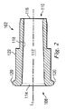
図1及び図2を参照すると、雌型チューブフィッティング102が、近位端部108から遠位端部110まで延在する概してチューブ状の形状を有することが示される。内部ボア112が雌型チューブフィッティング102を通って延在する。近位開口114が近位端部108において内部ボア112と連通し、遠位開口116が遠位端部110において内部ボア112と連通する。図示されるように、内部ボア112は、近位端部108から遠位端部110へ連続的に先細になる内面118によって画定される。この結果、内部ボア112はルアーテーパー(luer taper)を有する。
With reference to FIGS. 1 and 2, the
近位端部108において、雌型チューブフィッティング102は、外面122から延在する突起120又は羽部を含む。ここで、雌型チューブフィッティング102は一対の対向突起120を有し、一対の対向突起120は近位端部108の対向する側に位置付けられる。突起120は雌型チューブフィッティング102の長手方向の軸線L1に対して略横向きに延在する。さらに、各突起102は長手方向の軸線L1から反対向きに延在する。二つの突起120として示されているが、他の実施形態では、雌型チューブフィッティング102が二つ以上の突起120を有することが考えられる。以下により詳細に記載されるように、突起120は、雌型チューブフィッティング102を雄型チューブフィッティング104にロックすることを補助する。
At the
図1、図3及び図4を参照すると、雄型チューブフィッティング104は近位端部124から遠位端部126まで延在する。近位端部124はフランジ128を含み、遠位端部126は雄型プラグ130又はテーパー状の遠位端部を形成する。これに関連して、フランジ128は、雌型チューブフィッティング102と雄型チューブフィッティング104とを接続し且つ/又は接続解除する間に使用される牽引面又は把持面をシステム100の使用者に提供する。さらに、雄型プラグ130は、ルアーテーパーを有し、雌型チューブフィッティング102の内部ボア112内に受容されるような大きさに形成される。このため、フランジ128によって、使用者は、雌型チューブフィッティング102の内部ボア112内に雄型プラグ130を挿入する間又は雌型チューブフィッティング102の内部ボア112から雄型プラグ130を取り外す間、雄型チューブフィッティング104を把持できるようになる。この結果、フランジ128は雌型チューブフィッティング102と雄型チューブフィッティング104との間の容易な接続及び接続解除を補助する。
With reference to FIGS. 1, 3, and 4, male tube fitting 104 extends from
図示されるように、雄型チューブフィッティング104は、雄型チューブフィッティング104を通って延在する内部ボア132を含む。近位開口134が近位端部124において内部ボア132と連通し、遠位開口136が遠位端部126において内部ボア132と連通する。内部ボア132は内面138によって画定される。これに関連して、内面138は近位端部124から遠位端部126まで先細になり且つ/又は逓減する。この結果、雄型チューブフィッティング104の近位端部124における内部ボア132の直径は、雄型チューブフィッティング104の遠位端部126における内部ボアの直径よりも大きい。
As shown, male tube fitting 104 includes an
図1及び図4に最もよく示されるように、雄型チューブフィッティング104は、近位保持部材140又は環状瘤(annular nub)と、遠位保持部材142又は環状瘤とを含む。近位保持部材140及び遠位保持部材142は、雄型チューブフィッティング104の周囲の周りに延在し、雄型チューブフィッティング104の外面144に沿って、隆起した環状リング、部分及び又は隆起部を形成する。以下により詳細に記載されるように、近位保持部材140及び遠位保持部材142は、雄型チューブフィッティング104の外面144に沿った所望の位置にロックカラーを選択的に保持し且つ/又は保つべく、引っ込み式ロックカラー106と相互に作用する。
As best shown in FIGS. 1 and 4, the male tube fitting 104 includes a
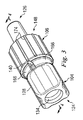
図1、図3及び図4を参照すると、引っ込み式ロックカラー106は近位端部146から遠位端部148まで延在する。図示されるように、内部ボア150が引っ込み式ロックカラー106を通って延在する。近位開口152は近位端部146において内部ボア150と連通し、遠位開口154は遠位端部148において内部ボア150と連通する。
With reference to FIGS. 1, 3 and 4, the
内部ボア150は内面156によって画定される。図5に最もよく示されるように、内面156はネジ山158、160又は傾斜面を含む。ネジ山158、160は内部ボア150内に二重の螺旋状ネジ山パターンを形成する。これに関連して、ネジ山158、160は、内面156の周りに周方向に延在するとき、反対方向に傾斜している。加えて、ネジ山158、160は、雌型チューブフィッティング102の突起120を取外し可能に受容するように構成された一対の対向空間162を形成する。以下、より詳細に記載されるように、突起120が空間162に設置されて、引っ込み式ロックカラー106が雄型チューブフィッティング104回りに第1の方向に回転されると、雄型チューブフィッティング104は雌型チューブフィッティング102とシール係合されて雌型チューブフィッティング102内にロックされる。
図示されるように、引っ込み式ロックカラー106の近位端部146は、解放部分164、開口部又はスリットを含む。これに関連して、引っ込み式ロックカラー106の外面166は解放部分164によって遮断される。解放部分164は、外面166から、内部ボア150を画定する内面156まで延在する。この結果、解放部分164は近位端部146の可撓性及び/又は弾性を増大する。このため、近位端部146は解放部分164によって弾性変形可能である。
As shown, the
引っ込み式ロックカラー106の近位端部146は、内部ボア150内に延在するテーパー状リップ168又はフランジも含む。これに関連して、テーパー状リップ168は近位開口152に隣接し且つ近位開口152を囲む。さらに、テーパー状リップ168は解放部分164によって遮断される。この結果、テーパー状リップ168は近位開口152の周りに非連続の環状リップを形成する。以下、より詳細に記載されるように、テーパー状リップ168は、雄型チューブフィッティング104の外面144に沿った既定の位置に引っ込み式ロックカラーを保持し且つ/又は保つべく、近位保持部材140及び遠位保持部材142と相互に作用する。
The
図3及び図4を参照すると、引っ込み式ロックカラー106は雄型チューブフィッティング104の外面144の周りに配置される。引っ込み式ロックカラー106は雄型チューブフィッティング104の外面144に沿って位置付けられるように構成される。これに関連して、引っ込み式ロックカラー106は、外面144に沿って移動するとき、雄型チューブフィッティング104回の長手方向の軸線L2の周りで、引っ込み、平行移動し、摺動し、移動し、且つ/又は自由に回転することができる。例えば、引っ込み式ロックカラー106は、雄型チューブフィッティング104の外面144の任意の位置に沿って、フランジ128の基部170の周りから雄型プラグ130の隆起部172まで位置付け可能である。
With reference to FIGS. 3 and 4, the
図1及び図3に最もよく示されるように、引っ込み式ロックカラー106は、外面164の周りに延在する複数の隆起部174を有する。これに関連して、隆起部174は把持面を提供し、把持面によって、使用者は、雄型チューブフィッティング104の周りに引っ込み式ロックカラー106を位置付ける間、把持面を保ち又は把持することができる。具体的には、隆起部174は、雄型チューブフィッティング104の周りで引っ込み式ロックカラー106を引っ込め、平行移動させ、摺動させ、移動させ、且つ/又は回転させるときに保持される面を提供する。
As best shown in FIGS. 1 and 3, the
さらに、図4は、近位保持部材140によって保持される引っ込み式ロックカラー106を示す。この位置では、引っ込み式ロックカラーは引っ込められた位置又は第1の位置にあると見なされる。図示されるように、引っ込み式ロックカラー106のテーパー状リップ168は基部位置の間に位置付けられる。加えて、引っ込められた位置では、近位保持部材140は、引っ込められたロックカラーのテーパー状リップ168に当接し、このことによってロックカラーを選択的に保持し、ロックカラーが外面144に沿って雄型プラグ130に向かって移動することを妨げる。このため、引っ込められた位置では、ロックカラーが選択的に保持され且つ/又はプラグに向かって摺動することが妨げられ、このことによってカラーがプラグの使用を妨害しないので、雄型チューブフィッティング104の雄型プラグ130はより容易にアクセス可能である。
Further, FIG. 4 shows the
図6は、ロック解除形態におけるルアーロックシステム100の断面図を示す。ロック解除形態では、引っ込み式ロックカラー106は近位保持部材140によって引っ込められた位置に選択的に保持される。引っ込められた位置において、テーパー状リップ168は、近位保持部材140に当接し、このことによって選択的にロックカラーが外面144に沿って雄型プラグ130に向かって移動することを妨げる。このため、引っ込められた位置では、ロックカラーが選択的に保持され且つ/又はプラグに向かって摺動することが妨げられ、このことによってカラーがプラグの使用を妨害しないので、雄型チューブフィッティング104の雄型プラグ130はより容易にアクセス可能である。
FIG. 6 shows a cross-sectional view of the
図6に示されるように、雄型プラグ130は近位開口114を通して雌型チューブフィッティング102の内部ボア112内に挿入された。上述されるように、引っ込み式ロックカラー106が引っ込められた位置にあるので、ロックカラーは選択的に保持され且つ/又はプラグに向かって摺動することが妨げられ、このことによってカラーが雌型チューブフィッティング102内へのプラグの挿入を妨害しない。さらに、引っ込み式ロックカラー106は、引っ込められた位置にあるとき、雌型チューブフィッティング102と雄型チューブフィッティングと104を互いにロックしない。このため、引っ込み式ロックカラー106が引っ込められた位置にある間、雄型プラグ130は雌型チューブフィッティング102の内部ボア112内に取外し可能に挿入可能である。言い換えれば、雄型プラグ130は、引っ込み式ロックカラー106が引っ込められた位置にあるとき、雌型チューブフィッティング102の内部ボア112内に挿入され且つ内部ボア112から取り外されることができる。したがって、ロック解除形態では、引っ込み式ロックカラー106は、引っ込められて、雌型チューブフィッティング102と雄型チューブフィッティング104とを互いにロックしない。
As shown in FIG. 6, the
さらに、雄型チューブフィッティング104と雌型チューブフィッティング102との接続の間、フランジ128は更に補助する。これに関連して、雄型チューブフィッティング104のフランジ128によって、使用者は、雄型プラグ130を内部ボア112内に挿入する間、雄型チューブフィッティング104をより容易に把持することができる。例えば、フランジ128は把持面を提供し、把持面によって、使用者は、雌型チューブフィッティング102と雄型チューブフィッティング104との接続の間、雄型チューブフィッティング104上で、捻り、押し、引き、且つ/又はこれらと均等のことができるようになる。加えて、ロック解除形態では、フランジ128は雄型チューブフィッティング104を雌型チューブフィッティング102内に位置付けることを助ける。
In addition, the
図7は、ロック形態におけるルアーロックシステム100の断面図を示す。図6に示されるロック解除形態から、引っ込み式ロックカラー106は、外面144に沿って移動され、ここでは、引っ込められてない位置において又は第2の位置において、遠位保持部材142によって保持される。図示されるように、引っ込み式ロックカラー106のテーパー状リップ168は、引っ込められてない位置にある間、遠位保持部材142と雄型プラグ130の隆起部172との間に位置付けられる。
FIG. 7 shows a cross-sectional view of the
引っ込められてない位置を実現するために、引っ込み式ロックカラー106は長手方向の軸線L2に沿って雄型プラグ130に向かって第1の方向に移動された。これに関連して、近位端部146が解放部分164によって増大した可撓性を有するので、近位端部146は、外面144に沿って雄型プラグ130に向かって移動するとき、近位保持部材140と遠位保持部材142とをそれぞれ通過すると、外面144から外側に離れるように変形し又は撓むことができる。具体的には、十分な力が雄型プラグ130の方向にロックカラーに印加されるとき、テーパー状リップ168は、近位保持部材140と遠位保持部材142とにそれぞれ当接すると、外面144から外側に離れるように撓む。この結果、テーパー状リップ168は、近位保持部材140と遠位保持部材142とをそれぞれ通過することができ、外面144に沿って雄型プラグ130に向かって移動し、引っ込められてない形態に変わる。したがって、引っ込められてない形態では、テーパー状リップ168は、遠位保持部材142に当接し、このことによって、ロックカラーを選択的に保持し、ロックカラーが長手方向の軸線L2に沿ってフランジ128に向かって反対の第2の方向に外面144に沿って動くことを妨げる。
To realize not retracted position,
加えて、図7は、雄型チューブフィッティング104が引っ込み式ロックカラー106を介して雌型チューブフィッティング102に互いにロックされることを示す。これに関連して、引っ込み式ロックカラー106は、突起120がカラーの空間162内に挿入されるように、突起120に対して整列された。さらに、引っ込み式ロックカラー106は、第1の方向(例えば時計回り)に長手方向の軸線L2回りに回転されて、雄型チューブフィッティング104と雌型チューブフィッティング102とを互いにシール係合し且つロックする。この結果、雌型チューブフィッティングの内部ボア112と雄型チューブフィッティング104の内部ボア132とは流体結合される。このため、引っ込み式ロックカラー106が引っ込められてない位置にある間、雄型プラグ130は雌型チューブフィッティング102の内部ボア112から取り外されることが妨げられる。したがって、ロック形態では、引っ込み式ロックカラー106は、雌型チューブフィッティング102と雄型チューブフィッティング104とを互いにロックし、このことによってそれぞれのチューブの内部ボアをシール係合する。
In addition, FIG. 7 shows that the male tube fitting 104 is locked together with the female tube fitting 102 via a
代替的な実施形態では、引っ込み式ロックカラー106は、別の方向(例えば反時計回り)に長手方向の軸線L2回りに回転されて、雄型チューブフィッティング104と雌型チューブフィッティング102とを互いにシール係合し且つロックするように構成されることに留意すべきである。斯かる代替的な実施形態では、引っ込み式ロックカラー106のネジ山158、160は、引っ込み式ロックカラー106の長手方向の軸線L2回りの反時計回りの回転によって雄型チューブフィッティング104と雌型チューブフィッティング102とが互いにシール係合され且つロックされるように方向付けられる。
In an alternative embodiment, the
さらに、引っ込み式ロックカラー106を介した雄型チューブフィッティング104の雌型チューブフィッティング102へのロックは、チューブフィッティングを回転させ又は捻ることなく生じうることに留意されたい。上述されたように、引っ込み式ロックカラー106は、雄型チューブフィッティング104に対して第1の方向に長手方向の軸線L2回りに回転して、雌型チューブフィッティング102と雄型チューブフィッティング104とをロックする。しかしながら、このロック工程の間、雌型チューブフィッティング102と雄型チューブフィッティング104とは必ずしも互いに対して回転されることを必要としない。結果として、雄型チューブと雌型チューブとを互いにロックすることは、チューブを互いにロックする引っ込み式ロックカラー106の結果として必要とされる捻り及び/又は回転の欠如によって単純化される。
Furthermore, it should be noted that locking the male tube fitting 104 to the female tube fitting 102 via the
加えて、引っ込み式ルアーロックシステム100は、図7に示されるロック形態から図6に示される非ロック形態に戻ることができる。これに関連して、雄型チューブフィッティング104と雌型チューブフィッティング102とは、雄型チューブフィッティング104に対して第2の方向(例えば反時計回り)に長手方向の軸線L2回りに引っ込み式ロックカラー106を回転させることによって、互いからロック解除されてもよい。さらに、図7に示されるロック形態から、引っ込み式ロックカラー106は、テーパー状リップ168が引っ込められた形態(図6参照)において近位保持部材140によって選択的に保持されるように、外面144に沿って移動される。近位端部146が解放部分164の結果として増大した可撓性を有するので、近位端部146は、フランジ128に向かって長手方向の軸線L2に沿って第2の方向に外面144に沿って移動するとき、遠位保持部材142と近位保持部材140とをそれぞれ通過すると、外面144(すなわち長手方向の軸線L2)から外側に離れるように撓み又は変形することができる。具体的には、十分な力がフランジ128に向かって第2の方向に引っ込み式ロックカラー106に印加されるとき、テーパー状リップ168は、遠位保持部材142と近位保持部材140とにそれぞれ当接すると、外面144から外側に離れるように変形し又は撓む。この結果、テーパー状リップ168は、選択的な保持部の遠位保持部材142と近位保持部材140とをそれぞれ通過することができ、引っ込み式ロックカラーが引っ込められた位置を呈するまで、外面144に沿ってフランジ128に向かって移動する。
In addition, the retractable
引っ込み式ルアーロックシステム100の使用例が以下に記載され、引っ込み式ルアーロックシステム100では、医療サービス提供者が引っ込み式ルアーロックシステム100を使用して手術器具を手術コンソールに流体結合する。雌型チューブフィッティング102が遠位端部110において手術器具に流体結合される。この結果、雌型チューブフィッティング102の内部ボア112が手術器具と流体連通する。
An example use of the retractable
雄型チューブフィッティング104が従来のプラスチックチューブの部品の第1端部に流体結合される。具体的には、チューブの部品の第1端部が近位開口134を通して雄型チューブフィッティング104の内部ボア132内に挿入される。プラスチックチューブの部品の反対の端部が手術コンソールに流体結合される。
A male tube fitting 104 is fluidly coupled to the first end of a conventional plastic tube component. Specifically, the first end of the tube component is inserted through the
その後、手術器具が手術コンソールに流体結合される。これに関連して、雄型プラグ130が雌型チューブフィッティング102の内部ボア112内に挿入される。より具体的には、引っ込み式ロックカラー106が、雄型プラグ130の内部ボア122内への挿入の間、引っ込められた位置にある。その後、引っ込み式ロックカラー106が雄型チューブフィッティング104の外面144に沿って引っ込められた位置から引っ込められてない位置へ摺動される。加えて、引っ込み式ロックカラー106の空間162が雌型チューブフィッティング102の突起120に対して整列される。カラーが引っ込められてない位置にあり且つ突起が空間162内に位置付けられた時点で、引っ込み式ロックカラー106が雄型チューブフィッティング104の長手方向の軸線L2回りに第1の方向(例えば時計回り)に回転される。斯かる回転によって雄型チューブフィッティング104と雌型チューブフィッティング102とが互いにシール状態でロックされる。したがって、引っ込み式ルアーロックシステム100は、雄型チューブフィッティングと雌型チューブフィッティングとが互いに対してシール係合されることを可能とする引っ込み式ルアーロックを提供する。
The surgical instrument is then fluidly coupled to the surgical console. In this regard, a
加えて、雄型チューブフィッティング104と雌型チューブフィッティング102とは、第1の方向とは反対の第2の方向(例えば反時計回り)に、雄型チューブフィッティング104の長手方向の軸線L2回りに引っ込み式ロックカラー106を回転させることによってロック解除されてもよい。さらに、いったんロック解除された引っ込み式ロックカラーは外面に沿って引っ込められた位置まで摺動される。引っ込められた位置では、引っ込み式ロックカラーはもはや雌型チューブフィッティング102と雄型チューブフィッティング104とを互いにロックしていない。この結果、雌型チューブフィッティング102から雄型チューブフィッティング104を引き、捻り、且つ/又は物理的に取り外すことを補助する把持面を提供するのにフランジ128が使用される。言い換えれば、引っ込み式ロックカラー106が引っ込められた位置にある状態では、雄型プラグ130を内部ボア112から取り外すことができ、このことによって雌型チューブフィッティング102と雄型チューブフィッティング104とを互いから物理的に接続解除することができる。
In addition, the male tube fitting 104 and the female tube fitting 102 are rotated about the longitudinal axis L 2 of the male tube fitting 104 in a second direction (eg, counterclockwise) opposite to the first direction. It may be unlocked by rotating the
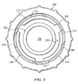
図8は、本開示の一つの態様に係る代替的な引っ込み式ロックカラー200の端面図を示す。引っ込み式ロックカラー200は引っ込み式ロックカラー106と同様である。さらに、ロックカラー200は引っ込み式ルアーロックシステム100においてロックカラー106の代わりに使用されることができる。さらに、簡潔にするために、ロックカラー200についての相違点のみが以下に記載される。
FIG. 8 illustrates an end view of an alternative
図示されるように、ロックカラー200は、内面204によって画定される内部ボア202を有する。内面204は、ネジ山206、208、210、212又は傾斜面を含む。ネジ山206、208、210、212は、内部ボア202内の内面204に沿って周方向に延在する四つの螺旋状ネジ山パターンを形成する。これに関連して、ネジ山206、208は、互いに対して反対方向に傾斜している一対の対向ネジ山を形成する。加えて、ネジ山210、212は、互いに対して反対方向に傾斜している一対の対向ネジ山を形成する。
As shown, the
加えて、ネジ山206、208は、雌型チューブフィッティング102の突起120を受容するための一対の対向空間214を作り出す。さらに、ネジ山210、212は、雌型チューブフィッティング102の突起120を受容するための一対の対向空間216を作り出す。このため、引っ込み式ロックカラー200は、突起120を受容するための四つの空間を有する。このため、突起120が空間214及び/又は216内に設置されて、ロックカラー200が回転されると、雄型チューブフィッティング104と雌型チューブフィッティング102とが互いにロックされる。したがって、引っ込み式ロックカラー200は、引っ込み式ロックカラー106に対して追加の空間及びネジ部を有する代替的なロックカラーを有する代替的なロックカラーを提供する。
In addition, the
さらに、雌型チューブフィッティング102が、引っ込み式ロックカラー200を使用するとき二つ以上の図1に示される突起120を含むことができることが考えられる。例えば、代替的な実施形態では、雌型チューブフィッティング102は二対の対向突起20を含むことができる。この結果、空間214、216の各々について突起120が存在する。
It is further contemplated that the female tube fitting 102 can include more than one
加えて、突起120が引っ込み式ロックカラーの空間に整列し且つ引っ込み式ロックカラーの空間内に位置付けられるような大きさである限り、突起120の数及び/又は形態は限定されるものではない。同様に、ネジ山によって形成された空間が、与えられた雌型チューブフィッティングに適合する限り、本明細書に開示された引っ込み式ロックカラーにおけるネジ山の数及び/形態は限定されるものではない。
In addition, the number and / or configuration of the
本開示が上述の実施形態によって示され、実施形態が幾分詳細に記載されてきたが、本開示の範囲が斯かる詳細に制限され又はいかなる態様でも限定されることを出願人は意図していない。追加の利点及び修正が当業者に容易に明らかである。このため、広い態様における本開示は、具体的な詳細、それぞれの装置及び方法、並びに示され且つ記載された説明のための例に限定されるものではない。したがって、出願人の一般的な思想又は独創的な概念の範囲を逸脱することなく、斯かる詳細から逸脱することができる。 While this disclosure has been illustrated by the above-described embodiments, and embodiments have been described in some detail, the applicant intends that the scope of this disclosure be limited to such details or in any manner. Absent. Additional advantages and modifications will be readily apparent to those skilled in the art. Thus, the present disclosure in its broader aspects is not limited to the specific details, respective devices and methods, and illustrative examples shown and described. Accordingly, departures may be made from such details without departing from the scope of the applicant's general idea or inventive concept.
Claims (5)
前記雄型プラグ(130)を受容するように構成された第2の内部ボア(112)を有する外面(122)を備えた雌型チューブフィッティング(102)と、
前記雄型チューブフィッティングの周りに配置され、前記長手方向の軸線に沿って第1の引っ込められた位置から第2のロック位置へ自由に摺動するように位置付けられたカラー(106)であって、前記第1の引っ込められた位置では、前記雄型プラグ(130)が前記雌型チューブフィッティングの第2の内部ボア内に取外し可能に挿入可能であるように、前記雄型チューブフィッティングと前記雌型チューブフィッティングとが互いに対してロック解除され、前記第2のロック位置では、前記雄型プラグが前記雌型チューブフィッティングの第2の内部ボアから取り外されることが妨げられるように、前記雄型チューブフィッティングと前記雌型チューブフィッティングとが互いに対してロックされる、カラー(106)と
を具備し、
前記カラー(106)が、該カラーを前記長手方向の軸線に沿って前記第1の引っ込められた位置から前記第2のロック位置まで摺動可能に位置付けるべく変形する弾性変形可能な部分(146)を含み、
前記弾性変形可能な部分が、前記長手方向の軸線から外側に撓むテーパー状リップ(168)と、前記テーパー状リップを隔てるとともに前記カラーの外面から該カラーの内面まで貫通して延在するスリット(164)と、を含み、
前記雄型チューブフィッティング(104)が外面(144)に近位環状瘤(140)を含み、前記近位環状瘤が前記テーパー状リップ(168)と相互に作用する近位保持部材として構成され、
前記テーパー状リップ(168)は、前記近位保持部材(140)を越えて選択的に前記第1の引っ込められた位置に前記カラー(106)を保持するように構成され、
前記テーパー状リップ(168)は、前記カラーがロックされた状態になるまで、前記隆起部(172)に向かって前記外面(144)に沿って移動可能である、医療システム。 A male tube fitting (104) extending along a longitudinal axis and having a first internal bore (132) and an end portion including a male plug (130) , the distal end A male tube fitting (104) comprising a ridge (172) on the outer surface (144) in the section ;
A female tube fitting (102) with an outer surface (122) having a second inner bore (112) configured to receive the male plug (130) ;
A collar (106) disposed about the male tube fitting and positioned to freely slide from a first retracted position to a second locked position along the longitudinal axis; The male tube fitting and the female so that, in the first retracted position, the male plug (130) can be removably inserted into a second internal bore of the female tube fitting. The male tube so that the male tube fittings are unlocked relative to each other, and in the second locked position, the male plug is prevented from being removed from the second internal bore of the female tube fitting. A collar (106) , wherein the fitting and the female tube fitting are locked against each other;
An elastically deformable portion (146) in which the collar (106) deforms to slidably position the collar along the longitudinal axis from the first retracted position to the second locked position. Including
A tapered lip (168), wherein the elastically deformable portion is bent outward from the longitudinal axis, and a slit extending through the collar from the outer surface to the collar inner surface while separating the tapered lip and (164), only including,
The male tube fitting (104) includes a proximal annulus (140) on an outer surface (144), wherein the proximal annulus is configured as a proximal retaining member that interacts with the tapered lip (168);
The tapered lip (168) is configured to selectively hold the collar (106) in the first retracted position beyond the proximal retaining member (140);
The medical system , wherein the tapered lip (168) is movable along the outer surface (144) toward the ridge (172) until the collar is locked .
Applications Claiming Priority (3)
| Application Number | Priority Date | Filing Date | Title |
|---|---|---|---|
| US13/213,519 US8777931B2 (en) | 2011-08-19 | 2011-08-19 | Retractable luer lock fittings |
| US13/213,519 | 2011-08-19 | ||
| PCT/US2012/046158 WO2013028273A1 (en) | 2011-08-19 | 2012-07-11 | Retractable luer lock fittings |
Publications (3)
| Publication Number | Publication Date |
|---|---|
| JP2014531227A JP2014531227A (en) | 2014-11-27 |
| JP2014531227A5 JP2014531227A5 (en) | 2015-07-02 |
| JP6122005B2 true JP6122005B2 (en) | 2017-04-26 |
Family
ID=47713152
Family Applications (1)
| Application Number | Title | Priority Date | Filing Date |
|---|---|---|---|
| JP2014526003A Active JP6122005B2 (en) | 2011-08-19 | 2012-07-11 | Medical system with retractable luer lock fitting |
Country Status (8)
| Country | Link |
|---|---|
| US (1) | US8777931B2 (en) |
| EP (1) | EP2731666B1 (en) |
| JP (1) | JP6122005B2 (en) |
| CN (1) | CN103813827B (en) |
| AU (1) | AU2012299372C1 (en) |
| CA (1) | CA2843724C (en) |
| ES (1) | ES2666047T3 (en) |
| WO (1) | WO2013028273A1 (en) |
Families Citing this family (41)
| Publication number | Priority date | Publication date | Assignee | Title |
|---|---|---|---|---|
| US8277386B2 (en) * | 2004-09-27 | 2012-10-02 | Volcano Corporation | Combination sensor guidewire and methods of use |
| US7998134B2 (en) | 2007-05-16 | 2011-08-16 | Icu Medical, Inc. | Medical connector |
| US7803140B2 (en) | 2005-07-06 | 2010-09-28 | Icu Medical, Inc. | Medical connector with closeable male luer |
| US9168366B2 (en) | 2008-12-19 | 2015-10-27 | Icu Medical, Inc. | Medical connector with closeable luer connector |
| US11628267B2 (en) * | 2010-08-04 | 2023-04-18 | Medline Industries, Lp | Universal medical gas delivery system |
| EP2545956A1 (en) * | 2011-07-15 | 2013-01-16 | Becton Dickinson France | Drug delivery device and adaptor |
| US8777931B2 (en) | 2011-08-19 | 2014-07-15 | Alcon Research, Ltd. | Retractable luer lock fittings |
| JP6553357B2 (en) | 2011-09-09 | 2019-07-31 | アイシーユー・メディカル・インコーポレーテッド | Medical connector with fluid-resistant mating interface |
| JP5999404B2 (en) * | 2011-11-28 | 2016-09-28 | 株式会社ジェイ・エム・エス | Medical syringe |
| US8985639B2 (en) * | 2011-12-13 | 2015-03-24 | Oridion Medical 1987 Ltd. | Luer connectors |
| US20140066900A1 (en) * | 2012-09-06 | 2014-03-06 | Corindus, Inc. | System for guide catheter control |
| DE102012022359A1 (en) * | 2012-11-15 | 2014-05-15 | Vetter Pharma-Fertigung GmbH & Co. KG | Attachment for a syringe or carpule |
| TWI507627B (en) * | 2012-12-03 | 2015-11-11 | Univ Nat Cheng Kung | Tube fitting assembly and tube fitting set |
| US10207096B2 (en) * | 2013-02-27 | 2019-02-19 | Fresenius Medical Care Holdings, Inc. | Fluid line connectors |
| US9346077B2 (en) * | 2013-03-15 | 2016-05-24 | The Sherwin-Williams Company | Quick fit adjustment mechanism for extension pole system for paint roller |
| US9347472B2 (en) * | 2013-03-15 | 2016-05-24 | The Sherwin-Williams Company | Extension pole mechanism for paint roller |
| US9993634B2 (en) | 2013-10-28 | 2018-06-12 | Becton, Dickinson And Company | Retention feature for soft interface connection |
| US9713503B2 (en) | 2013-12-04 | 2017-07-25 | Novartis Ag | Surgical utility connector |
| US10646705B2 (en) * | 2013-12-11 | 2020-05-12 | Jms Co., Ltd. | Male connector |
| US10359141B2 (en) | 2014-01-14 | 2019-07-23 | The Boeing Company | Tube fitting |
| US11262013B2 (en) | 2014-01-14 | 2022-03-01 | The Boeing Company | Tube fitting |
| US10060563B2 (en) * | 2014-01-14 | 2018-08-28 | The Boeing Company | Tube fitting |
| US9939095B2 (en) * | 2014-01-29 | 2018-04-10 | The Boeing Company | Tube fitting |
| DE102014101484A1 (en) * | 2014-02-06 | 2015-08-06 | Marco Systemanalyse Und Entwicklung Gmbh | connection system |
| EP3166566B1 (en) * | 2014-07-10 | 2019-10-16 | AbbVie Inc. | Systems and methods for tubing delivery |
| USD778912S1 (en) * | 2014-08-11 | 2017-02-14 | Apple Inc. | Crown for electronic device |
| US9604046B2 (en) * | 2014-11-03 | 2017-03-28 | Nordson Corporation | Protective caps for use with medical fluid fittings, and related methods |
| CN104606773A (en) * | 2015-03-04 | 2015-05-13 | 陈琪 | Multifunctional drainage catheter connection device and drainage system with multifunctional drainage catheter connection device |
| JP6468678B2 (en) * | 2015-04-02 | 2019-02-13 | 光陽産業株式会社 | Medical connection structure |
| WO2016191619A1 (en) * | 2015-05-27 | 2016-12-01 | Johnson Controls Technology Company | Actuator conduit adaptor |
| EP3302679A4 (en) * | 2015-05-28 | 2019-01-23 | Elcam Medical Agricultural Cooperative Association Ltd. | Rotating connector |
| JP6706893B2 (en) * | 2015-09-18 | 2020-06-10 | 日機装株式会社 | Lockable connection |
| JP6974313B2 (en) * | 2015-10-29 | 2021-12-01 | ライアン、エドウィンRYAN, Edwin | Ophthalmic instrument system |
| GB201608603D0 (en) * | 2016-05-16 | 2016-06-29 | Medical Device Creations Ltd | Improved fluid line connector device |
| USD835265S1 (en) * | 2016-07-08 | 2018-12-04 | Kitazato Corporation | Medical tube hub |
| JP1571465S (en) * | 2016-07-08 | 2017-03-13 | ||
| IT201700088895A1 (en) * | 2017-08-02 | 2019-02-02 | Luc & Bel S R L | Safety equipment in a male luer lock cap. |
| EP3668475A1 (en) * | 2017-08-15 | 2020-06-24 | Becton, Dickinson and Company | Spinning female luer with threadably removable feature |
| US11040153B2 (en) | 2018-04-19 | 2021-06-22 | Becton Dickinson and Company Limited | Syringe adapter with secure connection |
| US20220203048A1 (en) * | 2019-02-11 | 2022-06-30 | Intuitive Surgical Operations, Inc. | Medical device insufflation connection |
| USD907769S1 (en) * | 2019-03-01 | 2021-01-12 | Ben M. Khalaj | Syringe luer lock with stabilizer |
Family Cites Families (161)
| Publication number | Priority date | Publication date | Assignee | Title |
|---|---|---|---|---|
| US2545263A (en) | 1946-04-03 | 1951-03-13 | Morse Boulger Destructor Compa | Soft tubing connector |
| US3225435A (en) | 1965-05-07 | 1965-12-28 | Warner Lambert Pharmaceutical | Method for attaching connector elements to resiliently flexible tubing |
| US3394954A (en) | 1966-05-06 | 1968-07-30 | Sarns Inc | Tube coupling for medical appliances |
| US3623484A (en) | 1969-07-22 | 1971-11-30 | Rudolf R Schulte | Telescoping shunt system for physiological fluid |
| US3876234A (en) | 1973-01-11 | 1975-04-08 | Extracorporeal Med Spec | Twist-lock connector |
| US3941127A (en) | 1974-10-03 | 1976-03-02 | Froning Edward C | Apparatus and method for stereotaxic lateral extradural disc puncture |
| US4076285A (en) | 1975-08-01 | 1978-02-28 | Erika, Inc. | Laminar flow connector for conduits |
| US4046479A (en) | 1976-04-23 | 1977-09-06 | Paley Hyman W | Removable locking connector for luer fittings |
| US4069826A (en) | 1976-09-03 | 1978-01-24 | Barlow Mfg. Corporation | Surgical tube adapter clamp |
| US4133312A (en) | 1976-10-13 | 1979-01-09 | Cordis Dow Corp. | Connector for attachment of blood tubing to external arteriovenous shunts and fistulas |
| GB1588362A (en) | 1977-10-07 | 1981-04-23 | Wallace Ltd H G | Catheters |
| WO1980000067A1 (en) | 1978-06-19 | 1980-01-24 | Gambro Ab | Method and connecting piece for joining tubes |
| ZA793232B (en) * | 1978-07-03 | 1980-09-24 | Smiths Industries Ltd | Connectors |
| US4346703A (en) | 1979-01-23 | 1982-08-31 | Baxter Travenol Laboratories, Inc. | Solution container for continuous ambulatory peritoneal dialysis |
| US4639019A (en) | 1979-06-04 | 1987-01-27 | Baxter Travenol Laboratories, Inc. | Luer connection |
| US4296949A (en) | 1979-08-06 | 1981-10-27 | Abbott Laboratories | Rotatable connecting device for I.V. administration set |
| US4369991A (en) | 1979-10-04 | 1983-01-25 | Linder Gerald S | Connector for endotracheal tubes and catheters |
| FR2468059A1 (en) | 1979-10-16 | 1981-04-30 | Aguettant Lab | DEVICE FOR MEDICAL USE OF CONNECTION WITH SEALING BETWEEN TWO BITS FOR THE COMMUNICATION OF TWO VOLUMES |
| US4294250A (en) | 1979-12-07 | 1981-10-13 | Baxter Travenol Laboratories, Inc. | Luer lock connection device |
| US4810241A (en) | 1980-06-09 | 1989-03-07 | Rogers Phillip P | Ambulatory dialysis system and connector |
| US4346704A (en) | 1980-09-09 | 1982-08-31 | Baxter Travenol Laboratories, Inc. | Sleeve valve for parenteral solution device |
| US4439188A (en) | 1980-09-15 | 1984-03-27 | Baxter Travenol Laboratories, Inc. | Tube connector |
| US4425124A (en) | 1981-04-06 | 1984-01-10 | Womack Charles E | Catheter assembly |
| DE3114937C2 (en) | 1981-04-13 | 1985-08-22 | Fresenius AG, 6380 Bad Homburg | Connection device for medical instruments or lines |
| US4452473A (en) | 1982-07-26 | 1984-06-05 | Baxter Travenol Laboratories, Inc. | Luer connection system |
| US4451069A (en) | 1982-08-09 | 1984-05-29 | Smith Investment Company | Quick connect fluid coupling |
| US4511359A (en) | 1982-09-29 | 1985-04-16 | Manresa, Inc. | Sterile connection device |
| US4778447A (en) | 1983-05-20 | 1988-10-18 | Travenol European Research & Development Center | Connectors |
| EP0143517B1 (en) | 1983-09-02 | 1989-04-05 | Minntech Corporation | Implantable parenteral hyperalimentation catheter system |
| GB8324281D0 (en) | 1983-09-10 | 1983-10-12 | Smith & Nephew Ass | Rotating luer lock |
| US4607868A (en) | 1983-11-30 | 1986-08-26 | Baxter Travenol Laboratories, Inc. | Universal connector |
| US4573978A (en) | 1984-03-15 | 1986-03-04 | Medrad, Inc. | Angiographic syringe and connector for joining a catheter thereto |
| US4581012A (en) | 1984-12-05 | 1986-04-08 | I-Flow Corporation | Multilumen catheter set |
| US4642091A (en) | 1985-03-08 | 1987-02-10 | Kendall Mcgaw Laboratories, Inc. | Sterilant additive holder for CAPD sets |
| US4617012A (en) | 1985-10-29 | 1986-10-14 | Manresa, Inc. | Sterile connector with movable connection member |
| USD303013S (en) | 1986-06-19 | 1989-08-22 | Pacesetter Infusion, Ltd. | Female luer connector |
| IT207944Z2 (en) | 1986-07-25 | 1988-03-14 | Erba Farmitalia | LOCKING DEVICE OF A SYRINGE ON A BODY TO WHICH THE SYRINGE MUST BE COUPLED. |
| US4758023A (en) | 1987-05-14 | 1988-07-19 | The Singer Company | Removable connection assembly |
| US5135489A (en) | 1988-01-25 | 1992-08-04 | Baxter International Inc. | Pre-slit injection site and tapered cannula |
| DE3821154C1 (en) | 1988-06-23 | 1989-10-19 | B. Braun Melsungen Ag, 3508 Melsungen, De | |
| US6290676B1 (en) | 1989-07-24 | 2001-09-18 | Venetec International, Inc. | Catheter anchoring system |
| EP0411521A1 (en) | 1989-08-01 | 1991-02-06 | Abbott Laboratories | Connecting arrangement |
| US5047021A (en) | 1989-08-29 | 1991-09-10 | Utterberg David S | Male luer lock medical fitting |
| US5078699A (en) | 1989-09-22 | 1992-01-07 | Habley Medical Technology Corporation | Compact, easy to assemble, safety IV system |
| US5125915A (en) | 1990-03-02 | 1992-06-30 | Cardiopulmonics, Inc. | Locking y-connector for selective attachment to exterior of medical tubing |
| US5071413A (en) | 1990-06-13 | 1991-12-10 | Utterberg David S | Universal connector |
| US5176415A (en) | 1990-08-16 | 1993-01-05 | Choksi Pradip V | Taper fitting with protective skirt |
| US5203775A (en) | 1990-09-18 | 1993-04-20 | Medex, Inc. | Needleless connector sample site |
| US5201717A (en) | 1990-12-05 | 1993-04-13 | Philip Wyatt | Safety enclosure |
| USD339417S (en) | 1991-02-14 | 1993-09-14 | Sampson Richard K | Tubing connector |
| US5188610A (en) | 1991-10-18 | 1993-02-23 | Vetrisystems, Inc. | Fluid dispensing apparatus |
| WO1993015703A1 (en) | 1992-02-05 | 1993-08-19 | Inventive Systems, Inc. | Improved phacoemulsification handpiece |
| US5476454A (en) | 1992-02-11 | 1995-12-19 | Minntech Corporation | Balloon catheter lock adaptor for use with a resterilization system |
| US5310524A (en) | 1992-02-11 | 1994-05-10 | Minntech Corporation | Catheter reprocessing and sterilizing system |
| US5284475A (en) | 1992-07-21 | 1994-02-08 | Mackal Glenn H | Luer valve adapter with expandable end |
| US5630427A (en) | 1992-08-12 | 1997-05-20 | Scimed Life Systems, Inc. | Medical shaft movement control device and method |
| US5352215A (en) | 1992-08-26 | 1994-10-04 | Scimed Life Systems, Inc. | Y-adapter with a sideport radius |
| US5356396A (en) | 1992-09-29 | 1994-10-18 | Medical Associates Network Inc. | Infusion apparatus |
| US5292308A (en) | 1993-05-04 | 1994-03-08 | Ryan Dana W | Three piece intravenous line connector |
| DE4318101A1 (en) * | 1993-06-01 | 1994-12-08 | Sterimed Gmbh | Hose coupling |
| US5470324A (en) | 1993-07-01 | 1995-11-28 | Baxter International Inc. | Non-refluxing suction canister system and components therefor |
| JP3199524B2 (en) | 1993-08-06 | 2001-08-20 | 日本メジフィジックス株式会社 | Luer needle unit and syringe |
| AU1332795A (en) | 1993-11-30 | 1995-06-19 | Medex, Inc. | Plastic needleless valve housing for standard male luer locks |
| AU1331595A (en) | 1993-11-30 | 1995-06-19 | Medex, Inc. | Anti-reflux valve with environmental barrier |
| WO1995015194A1 (en) | 1993-11-30 | 1995-06-08 | Medex, Inc. | Slit septum needleless site with check valve |
| USD363542S (en) | 1994-04-22 | 1995-10-24 | Mcgaw, Inc. | Winged cannula |
| US5609584A (en) | 1994-05-18 | 1997-03-11 | Gettig Technologies, Inc. | Adaptor system for use with a syringe |
| US5466020A (en) | 1994-12-30 | 1995-11-14 | Valleylab Inc. | Bayonet connector for surgical handpiece |
| US5607392A (en) | 1995-01-13 | 1997-03-04 | Ryder International Corporation | Fixed needle connector for IV assembly and method of assembling |
| US5651776A (en) | 1995-03-22 | 1997-07-29 | Angiodynamics, Inc. | Luer-type connector |
| US5620427A (en) | 1995-04-27 | 1997-04-15 | David R. Kipp | Luer lock system |
| US5830189A (en) | 1995-06-07 | 1998-11-03 | Johnson & Johnson Medical, Inc. | Catheter hub to nose engagement |
| US5582600A (en) | 1995-08-03 | 1996-12-10 | Baxter International Inc. | Transfer set connector with a locking lid and a method of using the same |
| US6096022A (en) | 1995-08-31 | 2000-08-01 | Target Therapeutics Inc. | Bi-directional catheter |
| US5702374A (en) | 1995-11-14 | 1997-12-30 | Abbott Laboratories | Male luer connector assembly |
| US5697898A (en) | 1996-05-31 | 1997-12-16 | Surgical Design Corporation | Automated free flow mechanism for use in phacoemulsification, irrigation and aspiration of the eye |
| US5775744A (en) | 1996-06-14 | 1998-07-07 | National Coupling Inc. | Sleeve for quick disconnect coupling |
| US5797889A (en) | 1996-06-19 | 1998-08-25 | Becton Dickinson And Company | Medical device having a connector portion with an improved surface finish |
| US5855568A (en) | 1996-11-22 | 1999-01-05 | Liebel-Flarsheim Company | Angiographic syringe and luer connector |
| US6402207B1 (en) | 1997-06-09 | 2002-06-11 | Qd Enterprises, Llc | Safety indexed medical connectors |
| IT1293856B1 (en) | 1997-06-27 | 1999-03-10 | Borla Ind | TRANSDUCER-PROTECTOR DEVICE FOR BIOMEDICAL HEMODIALYSIS LINES |
| US6095572A (en) | 1998-01-20 | 2000-08-01 | Optimize Technologies, Inc. | Quarter turn quick connect fitting |
| US6183464B1 (en) | 1998-06-01 | 2001-02-06 | Inviro Medical Devices Ltd. | Safety syringe with retractable needle and universal luer coupling |
| WO2000002617A1 (en) | 1998-07-13 | 2000-01-20 | Jms Co., Ltd. | Medical tube connector device |
| DE19841869A1 (en) | 1998-09-14 | 2000-03-16 | Yilmaz Memduh | Infusion accessory connectors with higher contamination protection |
| USD435652S (en) | 1999-03-30 | 2000-12-26 | Alcon Laboratories, Inc. | Shielded female connector |
| US6562023B1 (en) | 1999-04-23 | 2003-05-13 | Deltec Inc. | Catheter connector including seal ring and method |
| JP3856981B2 (en) | 1999-04-27 | 2006-12-13 | テルモ株式会社 | Tube connection device |
| JP2000308686A (en) | 1999-04-27 | 2000-11-07 | Terumo Corp | Tube connection device |
| US6224588B1 (en) | 1999-05-04 | 2001-05-01 | Saf-T-Med | Flexible finger latching mechanism |
| ES2157799B1 (en) | 1999-06-04 | 2002-02-01 | Badia Marcelo Segura | PERFECTION IN CONNECTION DEVICES FOR CATHETERS, PERFUSION EQUIPMENT AND SYSTEMS INTENDED TO DRILL OR DRAIN LIQUIDS IN THE HUMAN BODY. |
| US6156025A (en) | 1999-06-17 | 2000-12-05 | Bracco Research Usa Inc. | Twist valve |
| US6332633B1 (en) | 1999-12-15 | 2001-12-25 | Elcam Plastic Kibbutz Bar-Am | Luer-type connector |
| USD454637S1 (en) | 2000-03-17 | 2002-03-19 | Astrazeneca Ab | Connector |
| US6595964B2 (en) | 2000-12-22 | 2003-07-22 | Baxter International Inc. | Luer activated thread coupler |
| FR2819418B1 (en) | 2001-01-17 | 2003-03-14 | Technoflex Sa | TRANSFER SET, ESPECIALLY FOR THE ADMINISTRATION OF A MIXTURE OF LIQUIDS FOR MEDICAL PURPOSES |
| US7316679B2 (en) | 2001-01-22 | 2008-01-08 | Venetec International, Inc. | Medical device connector fitting |
| ITTO20010140A1 (en) | 2001-02-16 | 2002-08-16 | Borla Ind | MALE LUER LOCK CONNECTOR FOR MEDICAL FLUID LINES. |
| DE20103653U1 (en) | 2001-03-02 | 2001-05-17 | Braun Melsungen Ag | Ureter drainage device |
| USD462759S1 (en) | 2001-08-07 | 2002-09-10 | Allergan Sales, Inc. | Manifold with tube fittings for Phaco machine |
| US6585683B2 (en) | 2001-09-19 | 2003-07-01 | Advanced Medical Optics, Inc. | Tubing management manifold with tubing captures |
| GB0125294D0 (en) | 2001-10-22 | 2001-12-12 | Bickford Smith Philip | Medical small-bore tubing connectors |
| JP3972665B2 (en) | 2002-01-25 | 2007-09-05 | 株式会社ジェイ・エム・エス | Aseptic connector system |
| ITTO20020111A1 (en) | 2002-02-08 | 2003-08-08 | Borla Ind | ,, MALE LUER LOCK CONNECTOR FOR MEDICAL FLUID LINES ,, |
| US6802836B2 (en) | 2002-02-19 | 2004-10-12 | Scimed Life Systems, Inc. | Low profile adaptor for use with a medical catheter |
| EP1485147A1 (en) | 2002-03-19 | 2004-12-15 | Andrew Zimmerman | Medical disconnection guard |
| ITTO20020276A1 (en) | 2002-03-27 | 2003-09-29 | Borla Ind | ,, MALE LUER LOCK CONNECTOR FOR MEDICAL FLUID LINES ,, |
| WO2003086210A1 (en) | 2002-04-16 | 2003-10-23 | Alcon Grieshaber Ag | Device for connecting a functional unit which can be detachably arranged on a housing |
| EP2292297B1 (en) | 2002-04-26 | 2020-06-03 | EMD Millipore Corporation | Disposable steam sterilisable medical valve |
| AUPS280102A0 (en) | 2002-06-07 | 2002-06-27 | Barrett, Graham David | Aspiration tubing |
| US20060047251A1 (en) | 2002-10-22 | 2006-03-02 | Philip Bickford Smith | Medical small-bore tubing system and kit |
| US20060106349A1 (en) * | 2002-10-24 | 2006-05-18 | Terumo Kabushiki Kaisha | Syringe, cap and method of producing prefilled syringe |
| JP4522071B2 (en) * | 2002-10-24 | 2010-08-11 | テルモ株式会社 | Syringe |
| USD483869S1 (en) | 2002-10-29 | 2003-12-16 | Pre Holding, Inc. | Tubing connector |
| US7291123B2 (en) | 2003-06-04 | 2007-11-06 | Gambro Lundia | Joint for fluid transport lines for medical use |
| US7377909B2 (en) | 2003-06-19 | 2008-05-27 | Claude L Rickerd | Connection assembly for use with splittable sheath |
| US20050251102A1 (en) * | 2003-09-26 | 2005-11-10 | Michael Hegland | Catheter connection systems and methods |
| US7153296B2 (en) | 2003-11-07 | 2006-12-26 | Mitchell Martin S | Releasable tubing connector |
| US7344527B2 (en) | 2003-11-19 | 2008-03-18 | Medical Components, Inc. | Luer with integrated clamp |
| CA2554783C (en) | 2004-02-27 | 2014-01-28 | Iperboreal Pharma S.R.L. | Apparatus for applying and removing closing means from an end portion of a tubular element and the use thereof in peritoneal dialysis |
| US7377915B2 (en) | 2004-04-01 | 2008-05-27 | C. R. Bard, Inc. | Catheter connector system |
| EP1755438A1 (en) | 2004-05-13 | 2007-02-28 | Stryker Gi Ltd | Connector for use with multilumen tubing |
| US7314238B2 (en) | 2004-05-28 | 2008-01-01 | American Sterilizer Company | Fluid connection |
| US7497484B2 (en) * | 2004-08-11 | 2009-03-03 | Smiths Medical Asd, Inc. | Medical coupling system |
| DE202004012714U1 (en) | 2004-08-12 | 2004-11-04 | Smiths Medical Deutschland Gmbh | Luer lock connector for medical devices |
| US8876750B2 (en) | 2004-09-27 | 2014-11-04 | Art, Limited | Coaxial tubing system for phacoemulsification handpieces |
| EP1807140B1 (en) | 2004-11-05 | 2010-07-07 | Gambro Lundia AB | Method for manufacturing a catheter for vascular access |
| US7523967B2 (en) | 2004-12-13 | 2009-04-28 | Alcon, Inc. | Tubing fitting |
| ITMO20050141A1 (en) | 2005-06-09 | 2006-12-10 | Aries S R L | CLOSING DEVICE FOR CONTAINERS OR LINES OF ADMINISTRATION OF MEDICINAL OR FERMACEUTICAL FLUIDS. |
| EP1738725A1 (en) | 2005-06-30 | 2007-01-03 | Wavelight Laser Technologie AG | Apparatus for eye surgery |
| US7998134B2 (en) | 2007-05-16 | 2011-08-16 | Icu Medical, Inc. | Medical connector |
| US20070032776A1 (en) | 2005-07-21 | 2007-02-08 | Skinner Allen W | Extended locking luer connector |
| ITTO20050515A1 (en) | 2005-07-25 | 2007-01-26 | Borla Ind | MEDICAL VALVE CONNECTOR |
| ITTO20050516A1 (en) | 2005-07-25 | 2007-01-26 | Borla Ind | MEDICAL CONNECTOR |
| JP4980927B2 (en) | 2005-11-25 | 2012-07-18 | 株式会社根本杏林堂 | Chemical liquid coupling device and chemical liquid injection device |
| US8048062B2 (en) | 2005-12-30 | 2011-11-01 | Boston Scientific Scimed, Inc. | Catheter assembly and method for internally anchoring a catheter in a patient |
| WO2007089309A2 (en) | 2006-01-30 | 2007-08-09 | The Regents Of The University Of California | Endovascular catheter air block |
| US20070224865A1 (en) | 2006-02-17 | 2007-09-27 | Fangrow Thomas F | Soft-grip medical connector |
| JP4769103B2 (en) | 2006-03-17 | 2011-09-07 | 日本シャーウッド株式会社 | connector |
| ITTO20060206A1 (en) | 2006-03-17 | 2007-09-18 | Borla Ind | VALVE VALVE FOR MEDICAL LINES |
| US8636719B2 (en) | 2006-03-24 | 2014-01-28 | Medical Components, Inc. | Luer connector assembly with clamping sleeve and method of use |
| FR2901481B1 (en) | 2006-05-24 | 2009-01-23 | Ace Dev Solution Soc A Respons | LUER LOCK MALE CONNECTOR |
| US7862539B2 (en) | 2006-06-01 | 2011-01-04 | Codan Us Corporation | System and method for infusing toxins using safety set, connect set and cyto admin set |
| JP2008005974A (en) | 2006-06-28 | 2008-01-17 | Nippon Sherwood Medical Industries Ltd | Lure fixing, fitting and connecting structure |
| US7658420B2 (en) | 2006-07-13 | 2010-02-09 | Parker-Hannifin Corporation | Quick-connect fitting with unlocking ring |
| ITMO20060018U1 (en) | 2006-09-07 | 2008-03-08 | Lucomed Spa | MULTIPURPOSE FITTING FOR BIOMEDICAL LINES. |
| AU2007312985B2 (en) | 2006-10-17 | 2013-05-30 | C. R. Bard, Inc. | Waste management system |
| US8905998B2 (en) | 2006-10-19 | 2014-12-09 | Medical Components, Inc. | Catheter tunneler adapter and methods of assembly to a catheter and use |
| US7988674B2 (en) | 2006-10-30 | 2011-08-02 | Medtronic, Inc. | Externally releasable body portal anchors and systems |
| DE102006053582B4 (en) | 2006-11-10 | 2019-11-14 | Carl Zeiss Meditec Ag | Plug handle for a hose line |
| WO2008144575A2 (en) | 2007-05-18 | 2008-11-27 | Optiscan Biomedical Corporation | Fluid injection and safety system |
| US20080303267A1 (en) | 2007-06-05 | 2008-12-11 | Schnell William J | Fluid flow connector permitting forceful lateral separation |
| ITMO20070240A1 (en) | 2007-07-19 | 2009-01-20 | Aries S R L | PERFECT CLOSING DEVICE FOR ADMINISTRATION LINES OF MEDICAL OR PHARMACEUTICAL FLUIDS FROM CONTAINERS AND SIMILAR |
| JP5041920B2 (en) | 2007-08-24 | 2012-10-03 | 日本コヴィディエン株式会社 | Lock connector |
| GB2451891A (en) | 2007-08-17 | 2009-02-18 | Univ Sheffield Hallam | Medical fluid connector with features to ensure correct coupling |
| ITRM20070512A1 (en) | 2007-10-02 | 2009-04-03 | Iperboreal Pharma Srl | CONNECTION DEVICE |
| WO2009076717A1 (en) | 2007-12-19 | 2009-06-25 | Opto Global Holdings Pty. Ltd. | Control flow devices, methods, and systems |
| ITTO20080059A1 (en) | 2008-01-29 | 2009-07-30 | Industrie Borla Spa | VALVE VALVE FOR MEDICAL LINES |
| EP2095841B1 (en) | 2008-02-29 | 2012-11-07 | F. Hoffmann-La Roche AG | Connection system for connecting a fluid line to a fluid reservoir |
| US8057095B2 (en) | 2009-04-23 | 2011-11-15 | Medtronic, Inc. | Multiple use temperature monitor adapter, system and method of using same |
| US8777931B2 (en) | 2011-08-19 | 2014-07-15 | Alcon Research, Ltd. | Retractable luer lock fittings |
-
2011
- 2011-08-19 US US13/213,519 patent/US8777931B2/en active Active
-
2012
- 2012-07-11 CN CN201280045606.6A patent/CN103813827B/en active Active
- 2012-07-11 ES ES12825476.0T patent/ES2666047T3/en active Active
- 2012-07-11 JP JP2014526003A patent/JP6122005B2/en active Active
- 2012-07-11 AU AU2012299372A patent/AU2012299372C1/en active Active
- 2012-07-11 WO PCT/US2012/046158 patent/WO2013028273A1/en active Application Filing
- 2012-07-11 CA CA2843724A patent/CA2843724C/en active Active
- 2012-07-11 EP EP12825476.0A patent/EP2731666B1/en active Active
Also Published As
| Publication number | Publication date |
|---|---|
| CA2843724A1 (en) | 2013-02-28 |
| US8777931B2 (en) | 2014-07-15 |
| AU2012299372C1 (en) | 2016-12-01 |
| CN103813827A (en) | 2014-05-21 |
| EP2731666A4 (en) | 2014-10-22 |
| EP2731666B1 (en) | 2018-02-28 |
| WO2013028273A1 (en) | 2013-02-28 |
| EP2731666A1 (en) | 2014-05-21 |
| CN103813827B (en) | 2016-11-09 |
| AU2012299372B2 (en) | 2016-06-02 |
| ES2666047T3 (en) | 2018-04-30 |
| JP2014531227A (en) | 2014-11-27 |
| US20130046287A1 (en) | 2013-02-21 |
| AU2012299372A1 (en) | 2014-02-20 |
| CA2843724C (en) | 2019-09-03 |
Similar Documents
| Publication | Publication Date | Title |
|---|---|---|
| JP6122005B2 (en) | Medical system with retractable luer lock fitting | |
| US10112030B2 (en) | Introducer sheath assembly having a locking dilator | |
| KR101575849B1 (en) | Improvements in or relating to tube coupling | |
| US9795766B2 (en) | Catheter assembly blood control device and related methods | |
| EP0869826B1 (en) | Luer lock system | |
| ES2208717T3 (en) | SYRINGE WITH SAFETY NEEDLE PROTECTOR. | |
| EP3197536B1 (en) | Enteral feeding connector | |
| JP6255475B2 (en) | Fixable syringe assembly and associated apparatus and method | |
| EP3505208B1 (en) | Needleless access device | |
| EP2545956A1 (en) | Drug delivery device and adaptor | |
| JP2012075495A (en) | Medical use knife connector | |
| JP2011056009A (en) | Medical connector | |
| JP7149957B2 (en) | Adapter for connecting drug delivery devices to connectors | |
| JP6268877B2 (en) | Medical connector | |
| JP7220182B2 (en) | Multi-lock counter connector | |
| WO2021186871A1 (en) | Connector set and female connector | |
| NL2020013B1 (en) | Multi-lumen luer connector | |
| WO2019188213A1 (en) | Medical connector | |
| JP2023528388A (en) | Tubing system including anti-reassembly mechanism | |
| US20120232481A1 (en) | Retractable Syringe Needle Assembly |
Legal Events
| Date | Code | Title | Description |
|---|---|---|---|
| A521 | Request for written amendment filed |
Free format text: JAPANESE INTERMEDIATE CODE: A523 Effective date: 20150515 |
|
| A621 | Written request for application examination |
Free format text: JAPANESE INTERMEDIATE CODE: A621 Effective date: 20150515 |
|
| A131 | Notification of reasons for refusal |
Free format text: JAPANESE INTERMEDIATE CODE: A131 Effective date: 20160209 |
|
| A977 | Report on retrieval |
Free format text: JAPANESE INTERMEDIATE CODE: A971007 Effective date: 20160212 |
|
| A521 | Request for written amendment filed |
Free format text: JAPANESE INTERMEDIATE CODE: A523 Effective date: 20160427 |
|
| A02 | Decision of refusal |
Free format text: JAPANESE INTERMEDIATE CODE: A02 Effective date: 20160927 |
|
| A521 | Request for written amendment filed |
Free format text: JAPANESE INTERMEDIATE CODE: A523 Effective date: 20161219 |
|
| A911 | Transfer to examiner for re-examination before appeal (zenchi) |
Free format text: JAPANESE INTERMEDIATE CODE: A911 Effective date: 20161228 |
|
| TRDD | Decision of grant or rejection written | ||
| A01 | Written decision to grant a patent or to grant a registration (utility model) |
Free format text: JAPANESE INTERMEDIATE CODE: A01 Effective date: 20170228 |
|
| A61 | First payment of annual fees (during grant procedure) |
Free format text: JAPANESE INTERMEDIATE CODE: A61 Effective date: 20170330 |
|
| R150 | Certificate of patent or registration of utility model |
Ref document number: 6122005 Country of ref document: JP Free format text: JAPANESE INTERMEDIATE CODE: R150 |
|
| S111 | Request for change of ownership or part of ownership |
Free format text: JAPANESE INTERMEDIATE CODE: R313111 Free format text: JAPANESE INTERMEDIATE CODE: R313113 |
|
| R350 | Written notification of registration of transfer |
Free format text: JAPANESE INTERMEDIATE CODE: R350 |
|
| R250 | Receipt of annual fees |
Free format text: JAPANESE INTERMEDIATE CODE: R250 |
|
| R250 | Receipt of annual fees |
Free format text: JAPANESE INTERMEDIATE CODE: R250 |
|
| R250 | Receipt of annual fees |
Free format text: JAPANESE INTERMEDIATE CODE: R250 |
|
| R250 | Receipt of annual fees |
Free format text: JAPANESE INTERMEDIATE CODE: R250 |