JP6468678B2 - Medical connection structure - Google Patents
Medical connection structure Download PDFInfo
- Publication number
- JP6468678B2 JP6468678B2 JP2016536789A JP2016536789A JP6468678B2 JP 6468678 B2 JP6468678 B2 JP 6468678B2 JP 2016536789 A JP2016536789 A JP 2016536789A JP 2016536789 A JP2016536789 A JP 2016536789A JP 6468678 B2 JP6468678 B2 JP 6468678B2
- Authority
- JP
- Japan
- Prior art keywords
- operation cylinder
- engagement
- connection
- engaging
- screwing
- Prior art date
- Legal status (The legal status is an assumption and is not a legal conclusion. Google has not performed a legal analysis and makes no representation as to the accuracy of the status listed.)
- Active
Links
Images


Classifications
-
- A—HUMAN NECESSITIES
- A61—MEDICAL OR VETERINARY SCIENCE; HYGIENE
- A61M—DEVICES FOR INTRODUCING MEDIA INTO, OR ONTO, THE BODY; DEVICES FOR TRANSDUCING BODY MEDIA OR FOR TAKING MEDIA FROM THE BODY; DEVICES FOR PRODUCING OR ENDING SLEEP OR STUPOR
- A61M39/00—Tubes, tube connectors, tube couplings, valves, access sites or the like, specially adapted for medical use
- A61M39/10—Tube connectors; Tube couplings
- A61M39/1055—Rotating or swivel joints
-
- A—HUMAN NECESSITIES
- A61—MEDICAL OR VETERINARY SCIENCE; HYGIENE
- A61M—DEVICES FOR INTRODUCING MEDIA INTO, OR ONTO, THE BODY; DEVICES FOR TRANSDUCING BODY MEDIA OR FOR TAKING MEDIA FROM THE BODY; DEVICES FOR PRODUCING OR ENDING SLEEP OR STUPOR
- A61M39/00—Tubes, tube connectors, tube couplings, valves, access sites or the like, specially adapted for medical use
- A61M39/10—Tube connectors; Tube couplings
- A61M2039/1033—Swivel nut connectors, e.g. threaded connectors, bayonet-connectors
-
- A—HUMAN NECESSITIES
- A61—MEDICAL OR VETERINARY SCIENCE; HYGIENE
- A61M—DEVICES FOR INTRODUCING MEDIA INTO, OR ONTO, THE BODY; DEVICES FOR TRANSDUCING BODY MEDIA OR FOR TAKING MEDIA FROM THE BODY; DEVICES FOR PRODUCING OR ENDING SLEEP OR STUPOR
- A61M39/00—Tubes, tube connectors, tube couplings, valves, access sites or the like, specially adapted for medical use
- A61M39/10—Tube connectors; Tube couplings
- A61M2039/1038—Union screw connectors, e.g. hollow screw or sleeve having external threads
-
- A—HUMAN NECESSITIES
- A61—MEDICAL OR VETERINARY SCIENCE; HYGIENE
- A61M—DEVICES FOR INTRODUCING MEDIA INTO, OR ONTO, THE BODY; DEVICES FOR TRANSDUCING BODY MEDIA OR FOR TAKING MEDIA FROM THE BODY; DEVICES FOR PRODUCING OR ENDING SLEEP OR STUPOR
- A61M39/00—Tubes, tube connectors, tube couplings, valves, access sites or the like, specially adapted for medical use
- A61M39/10—Tube connectors; Tube couplings
- A61M2039/1044—Verifying the connection, e.g. audible feedback, tactile feedback, visual feedback, using external light sources
-
- A—HUMAN NECESSITIES
- A61—MEDICAL OR VETERINARY SCIENCE; HYGIENE
- A61M—DEVICES FOR INTRODUCING MEDIA INTO, OR ONTO, THE BODY; DEVICES FOR TRANSDUCING BODY MEDIA OR FOR TAKING MEDIA FROM THE BODY; DEVICES FOR PRODUCING OR ENDING SLEEP OR STUPOR
- A61M39/00—Tubes, tube connectors, tube couplings, valves, access sites or the like, specially adapted for medical use
- A61M39/22—Valves or arrangement of valves
- A61M2039/229—Stopcocks
-
- A—HUMAN NECESSITIES
- A61—MEDICAL OR VETERINARY SCIENCE; HYGIENE
- A61M—DEVICES FOR INTRODUCING MEDIA INTO, OR ONTO, THE BODY; DEVICES FOR TRANSDUCING BODY MEDIA OR FOR TAKING MEDIA FROM THE BODY; DEVICES FOR PRODUCING OR ENDING SLEEP OR STUPOR
- A61M5/00—Devices for bringing media into the body in a subcutaneous, intra-vascular or intramuscular way; Accessories therefor, e.g. filling or cleaning devices, arm-rests
- A61M5/178—Syringes
Description
本発明は、医療用の接続構造に関する。 The present invention relates to a medical connection structure.
特許文献1に開示されているように、チューブ等の医療構成要素同士を接続するために雄型コネクタと雌型コネクタとを備えた医療用接続構造は周知である。雄型コネクタは、外周がテーパをなす雄型ルアー部を有し、雌型コネクタは内周がテーパをなす雌型ルアー部を有している。これら雄型コネクタと雌型コネクタは互いに螺合されるようになっており、この螺合を進めると、雄型ルアー部と雌型ルアー部が押圧力をもって接合し、所望のシール性能が得られるようになっている。
As disclosed in
上記接続構造において、螺合の締付けが緩いと、十分なシール性能が得られず、衝撃を受けた時にコネクタの接続状態が解除されてしまうこともある。
螺合の締付けが過剰になると、雄型ルアー部と雌型ルアー部が強く噛みついてしまう。そのため、コネクタの接続解除が必要になった場合に螺合を緩めることができず、他のコネクタと再接続することもできない。また、過剰な締付けトルクにより、雄型ルアー部や雌型ルアー部にひび割れ等の破損が生じることもある。In the above connection structure, if the screwing is loose, sufficient sealing performance may not be obtained, and the connection state of the connector may be released upon impact.
If the screwing is excessively tightened, the male luer part and the female luer part are strongly engaged. Therefore, when it is necessary to disconnect the connector, the screwing cannot be loosened and it cannot be reconnected to another connector. Further, excessive tightening torque may cause damage such as cracks in the male luer part and the female luer part.
特許文献2では、上記雄型コネクタと雌型コネクタの一方にストッパを設け、このストッパにより螺合深さを規制し、過剰締付け防止を図っている。
In
しかし、特許文献2の構成では、製造誤差により、規制される螺合深さと良好なシール性を確保するための締付けトルクとの関係に大きな誤差が生じ、そのため、過剰締付け防止と良好なシール性の両方を実現できないこともある。
However, in the configuration of
本発明は上記課題を解決するためになされたものであり、第1接続部分と第2接続部分とを備え、
上記第1接続部分と上記第2接続部分が、互いに螺合する第1螺合部と第2螺合部をそれぞれ有するとともに、この螺合を進めることにより互いに接合する第1シール部と第2シール部をそれぞれ有し、
上記第1シール部と第2シール部の一方は外周がテーパをなす雄型ルアー部であり、他方は内周がテーパをなす雌型ルアー部であり、上記雄型ルアー部の外周と上記雌型ルアー部の内周が接合することにより、上記雄型ルアー部と上記雌型ルアー部との間がシールされる医療用接続構造において、
上記第1接続部分は上記第1螺合部と一体をなす支持部を有し、この支持部の外周に操作筒が取り付けられ、これら第1接続部分の支持部と操作筒との間にトルクリミット機構が設けられ、このトルクリミット機構は、
(ア)上記操作筒を上記第2接続部分に対して螺合緩み方向に回した時には、上記操作筒と一緒に上記第1接続部分の上記支持部が回り、
(イ)上記操作筒を上記第2接続部分に対して螺合進み方向に回す過程において、上記操作筒に付与される回転トルクが所定トルクに達するまで、上記操作筒と一緒に上記第1接続部分の上記支持部が回り、
(ウ)上記操作筒を上記第2接続部分に対して螺合進み方向に回す過程において、上記第1シール部と第2シール部の接合により生じる抵抗を受けて上記操作筒の回転トルクが所定トルクに達した時には、上記操作筒が上記第1接続部分の上記支持部に対して空回りする
ように構成されていることを特徴とする。The present invention has been made to solve the above problems, and includes a first connection portion and a second connection portion,
The first connection part and the second connection part respectively have a first screw part and a second screw part that are screwed together, and a first seal part and a second screw that are joined together by advancing the screwing. Each has a seal part,
One of the first seal portion and the second seal portion is a male luer portion whose outer periphery is tapered, and the other is a female luer portion whose inner periphery is tapered, the outer periphery of the male luer portion and the female luer portion In the medical connection structure in which the gap between the male luer part and the female luer part is sealed by joining the inner periphery of the mold luer part.
The first connection portion has a support portion that is integral with the first screwing portion, and an operation cylinder is attached to the outer periphery of the support portion, and torque is provided between the support portion of the first connection portion and the operation tube. A limit mechanism is provided, and this torque limit mechanism is
(A) When the operation tube is rotated in the screwing loosening direction with respect to the second connection portion, the support portion of the first connection portion rotates together with the operation tube,
(A) In the process of turning the operation cylinder in the threading advance direction with respect to the second connection portion, the first connection together with the operation cylinder until the rotational torque applied to the operation cylinder reaches a predetermined torque. The above support part of the part turns,
(C) In the process of turning the operation cylinder in the threading advance direction with respect to the second connection portion, the rotational torque of the operation cylinder is predetermined by receiving resistance generated by joining the first seal portion and the second seal portion. When the torque is reached, the operation cylinder is configured to idle with respect to the support portion of the first connection portion.
上記構成によれば、所定トルクによる第1、第2シール部間の良好なシール性を確保できるとともに、過剰な締付けを回避できるため第1、第2シール部の噛み付きや破損を防止できる。 According to the above configuration, good sealing performance between the first and second seal portions by a predetermined torque can be secured, and excessive tightening can be avoided, so that the first and second seal portions can be prevented from being bitten or damaged.
好ましくは、上記トルクリミット機構は、上記第1接続部分の上記支持部に形成された第1係合部と、上記操作筒に形成された第2係合部とを有し、
上記操作筒を上記第2接続部分に対して螺合緩み方向に回した時には、上記第2係合部の一方側がこれと周方向に対向する上記第1係合部の一方側に係止されることにより、上記操作筒と一緒に上記第1接続部分の上記支持部が回り、
上記操作筒を上記第2接続部分に対して螺合進み方向に回す過程において、上記第2係合部の他方側が上記第1係合部の他方側に係止されることにより、上記操作筒に付与される回転トルクが所定トルクに達するまで、上記操作筒と一緒に上記第1接続部分の上記支持部が回り、
上記操作筒を上記第2接続部分に対して螺合進み方向に回す過程において、上記第1シール部と第2シール部の接合により生じる抵抗を受けて上記操作筒の回転トルクが所定トルクに達した時には、上記第2係合部が上記第1係合部を超えることにより、上記操作筒が空回りする。
上記構成によれば、トルクリミット機構を比較的簡単な構成とすることができる。Preferably, the torque limit mechanism includes a first engagement portion formed on the support portion of the first connection portion, and a second engagement portion formed on the operation cylinder.
When the operation tube is rotated in the screwing loosening direction with respect to the second connection portion, one side of the second engagement portion is locked to one side of the first engagement portion opposed to the second engagement portion in the circumferential direction. By rotating the support portion of the first connection portion together with the operation cylinder,
In the process of turning the operation cylinder in the screwing advance direction with respect to the second connection portion, the other side of the second engagement portion is locked to the other side of the first engagement portion, thereby the operation cylinder. Until the rotational torque applied to reaches a predetermined torque, the support portion of the first connection portion rotates together with the operation cylinder,
In the process of turning the operation cylinder in the threading advance direction with respect to the second connection portion, the rotational torque of the operation cylinder reaches a predetermined torque due to the resistance generated by the joining of the first seal portion and the second seal portion. When the operation is performed, the operation tube is idled by the second engagement portion exceeding the first engagement portion.
According to the said structure, a torque limit mechanism can be made into a comparatively simple structure.
好ましくは、上記第2係合部の上記一方側と上記第1係合部の上記一方側が急峻な係止面をそれぞれ有し、上記第2係合部の上記他方側と上記第1係合部の上記他方側の少なくとも一方が、傾斜面を有する。
上記構成によれば、操作筒を螺合緩み方向に回した時には、第1、第2係合部の係止面同士が当たることにより、確実に第1、第2接続部分の接続を解除できる。また、操作筒を螺合進み方向に回した時には、第1、第2係合部の少なくともいずれか一方の傾斜面の作用により、トルク管理を行うことができる。Preferably, the one side of the second engagement portion and the one side of the first engagement portion each have a steep locking surface, and the other side of the second engagement portion and the first engagement At least one of the other side of the part has an inclined surface.
According to the above configuration, when the operation cylinder is rotated in the screwing loosening direction, the first and second connection portions can be reliably disconnected by contact of the locking surfaces of the first and second engagement portions. . Further, when the operating cylinder is rotated in the screwing advance direction, torque management can be performed by the action of at least one of the inclined surfaces of the first and second engaging portions.
好ましくは、上記操作筒が上記第1接続部分の上記支持部に軸方向移動不能に取り付けられ、上記支持部の外周と上記操作筒の内周は、互いに径方向に対向する環状の第1係合部形成領域と第2係合部形成領域をそれぞれ有し、上記第1係合部形成領域には周方向に等間隔をおいて上記第1係合部が複数形成され、上記第2係合部形成領域には周方向に等間隔をおいて上記第2係合部が複数形成され、上記操作筒の回転トルクが所定トルクに達した時には、上記操作筒の弾性変形を伴って上記第2係合部が上記第1係合部を超える。
上記構成によれば、操作筒の弾性を利用してトルク管理を行うことができ、構成を簡略化できる。また、操作筒が空回りすると、第2係合部が第1係合部を超えてから弾性復帰する時にクリック音が発生するため、所定トルクに達したことを接続作業者に報せることができる。Preferably, the operation tube is attached to the support portion of the first connection portion so as not to be axially movable, and an outer periphery of the support portion and an inner periphery of the operation tube are annular first engagements that face each other in the radial direction. A plurality of first engaging portions are formed at equal intervals in the circumferential direction in the first engaging portion forming region; A plurality of the second engaging portions are formed at equal intervals in the circumferential direction in the joint forming region, and when the rotational torque of the operation tube reaches a predetermined torque, the second engagement portion is accompanied by elastic deformation of the operation tube. Two engaging parts exceed the first engaging part.
According to the said structure, torque management can be performed using the elasticity of an operating cylinder, and a structure can be simplified. Further, when the operation cylinder is idle, a click sound is generated when the second engagement portion elastically returns after exceeding the first engagement portion, so that it is possible to inform the connection worker that the predetermined torque has been reached. .
好ましくは、上記操作筒には周方向に等間隔をおいて複数の弾性変形部が形成され、これら弾性変形部は互いに独立して径方向に弾性変形可能であり、各弾性変形部の内面に上記第2係合部が形成されている。
上記構成によれば、複数の弾性変形部での弾性を利用することにより、トルク管理を行うことができる。Preferably, the operation cylinder is formed with a plurality of elastically deforming portions at equal intervals in the circumferential direction, and these elastically deforming portions can be elastically deformed in the radial direction independently of each other. The second engaging portion is formed.
According to the said structure, torque management can be performed by utilizing the elasticity in a some elastic deformation part.
好ましくは、上記操作筒の軸方向一端部には、軸方向に延びる複数のスリットが周方向に等間隔をおいて形成され、上記スリット間の部位が上記弾性変形部として提供される。この構成によれば、弾性変形部を簡単な形状とすることができる。
なお、上記操作筒には、U字形状をなす複数のスリットが周方向に等間隔をおいて形成され、これらスリットにより囲われた部位が上記弾性変形部として提供されるようにしてもよい。Preferably, a plurality of slits extending in the axial direction are formed at equal intervals in the circumferential direction at one axial end portion of the operation cylinder, and a portion between the slits is provided as the elastic deformation portion. According to this structure, an elastic deformation part can be made into a simple shape.
The operation cylinder may be formed with a plurality of U-shaped slits at equal intervals in the circumferential direction, and a portion surrounded by the slits may be provided as the elastic deformation portion.
一態様では、上記支持部の上記第1係合部形成領域には、上記第1係合部としての係合凹部が形成され、上記操作筒の上記第2係合部形成領域には、上記第2係合部としての係合凸部が形成され、上記操作筒に回転トルクが付与されない状態において、上記係合凸部が上記係合凹部に収容されている。
他の態様では、上記支持部の上記第1係合部形成領域には、上記第1係合部としての係合凸部が形成され、上記操作筒の上記第2係合部形成領域には、上記第2係合部としての係合凹部が形成され、上記操作筒に回転トルクが付与されない状態において、上記係合凸部が上記係合凹部に収容されている。In one aspect, an engagement recess as the first engagement portion is formed in the first engagement portion formation region of the support portion, and the second engagement portion formation region of the operation cylinder is An engaging convex portion is formed as a second engaging portion, and the engaging convex portion is accommodated in the engaging concave portion in a state where rotational torque is not applied to the operation cylinder.
In another aspect, an engagement convex portion as the first engagement portion is formed in the first engagement portion formation region of the support portion, and the second engagement portion formation region of the operation cylinder is formed in the second engagement portion formation region. An engagement recess as the second engagement portion is formed, and the engagement protrusion is accommodated in the engagement recess in a state where no rotational torque is applied to the operation cylinder.
上記第1接続部分および上記第2接続部分が、通路を有する第1医療構成要素と第2医療構成要素にそれぞれ設けられ、上記第1接続部分と第2接続部分の接続により、上記第1、第2の医療構成要素の通路が互いに連なる。医療構成要素としては、例えばチューブ、活栓、シリンジ等がある。 The first connection portion and the second connection portion are respectively provided in a first medical component and a second medical component having a passage, and by connecting the first connection portion and the second connection portion, the first, The passages of the second medical component are connected to each other. Examples of the medical component include a tube, a stopcock, and a syringe.
シリンジに用いられる場合の具体的態様の一つとして、上記第1接続部分が、雌型ルアー部材とこの雌型ルアー部材に着脱可能な筒形状のアタッチメントを備えている。上記雌型ルアー部材が上記第1シール部としての上記雌型ルアー部を有する。上記アタッチメントが円筒部を有している。この円筒部の外周部が上記支持部として提供される。この円筒部の内周には、上記第1螺合部としての雌ねじ部が形成されている。上記シリンジの液流出部が上記第2接続部分として提供される。この液流出部は、その先端部に上記第2シール部としての上記雄型ルアー部と、上記第2螺合部としての雄ねじ部を有する。 As one of the specific modes when used in a syringe, the first connecting portion includes a female luer member and a cylindrical attachment that can be attached to and detached from the female luer member. The female luer member has the female luer part as the first seal part. The attachment has a cylindrical portion. An outer peripheral portion of the cylindrical portion is provided as the support portion. On the inner periphery of the cylindrical portion, a female screw portion as the first screwing portion is formed. A liquid outflow portion of the syringe is provided as the second connection portion. The liquid outflow portion has the male luer portion as the second seal portion and the male screw portion as the second screwing portion at the tip.
上記第1接続部分と上記第2接続部分の一方が、通路を有する医療構成要素に設けられ、他方が上記通路を閉じる閉塞部材として提供される。
上記構成によれば、医療構成要素の通路を塞ぐ閉塞部材の接続作業において、締付けトルクを管理することができる。One of the first connection portion and the second connection portion is provided in a medical component having a passage, and the other is provided as an occlusion member that closes the passage.
According to the above configuration, it is possible to manage the tightening torque in the connecting operation of the blocking member that blocks the passage of the medical component.
本発明によれば、医療用接続構造において、良好なシール性を確保できるとともに、過剰締付けを防止できる。 According to the present invention, in the medical connection structure, it is possible to ensure a good sealing property and to prevent excessive tightening.
以下、本発明を図面を参照しながら説明する。
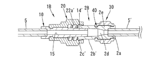
図1〜図6に示す本発明の第1実施形態に係る医療用接続構造は、薬液や血液等の液体を流すチューブ5、5’(第1、第2の医療構成要素)同士を接続するものである。図1に示すように、この接続構造は、雄型コネクタ1(第1接続部分)と雌型コネクタ2(第2接続部分)とを備えている。The present invention will be described below with reference to the drawings.
The medical connection structure according to the first embodiment of the present invention shown in FIG. 1 to FIG. 6 connects
最初に構成が簡単な雌型コネクタ2について説明する。雌型コネクタ2は、細長い筒形状をなす雌型ルアー部材により構成されており、基端から先端に向かって順に連結部2aと雌型ルアー部2b(第2シール部)とを有している。連結部2aにはチューブ5’の先端が挿入固定される。上記雌型ルアー部2bの先端部外周には一対の突起2c(第2螺合部)が周方向に180°離れて形成されている。
First, the
上記雌型ルアー部2bの内周は先端に向かって径が大きくなるような緩やかなテーパをなしている。雌型コネクタ2はその中心軸線に沿って貫通する通路2dを有している。この通路2dが上記チューブ5’の通路に連なっている。
The inner periphery of the
上記雄型コネクタ1は、雄型ルアー部材10と、この雄型ルアー部材10の外周に回転可能かつ軸方向移動不能に取り付けられた螺合部材20とを有している。
The
図4に示すように、雄型ルアー部材10は細長い筒形状をなし、基端から先端に向かって順に連結部11,受部13,雄型ルアー部14(第1シール部)を有している。連結部11にはチューブ5の先端が挿入固定されている。受部13の外周は円筒面をなしている。雄型ルアー部14の外周は先端に向かって径が小さくなるようなテーパをなしている。この雄型ルアー部14の外周のテーパ角は雌型ルアー部2bの内周のテーパ角と実質的に等しい。
雄型ルアー部材10の外周には、上記連結部11と受部13の境に位置する環状の係合溝12が形成されている。
雄型ルアー部材10は、その中心軸線に沿って貫通する通路15を有している。この通路15がチューブ5の通路と連なっている。As shown in FIG. 4, the
On the outer periphery of the
The
上記螺合部材20は、筒形状をなし、基端側の小径の円筒部21と先端側の大径の円筒部22とを有している。円筒部21の基端には径方向、内方向に突出する環状の係合凸部21aが形成されている。
上記螺合部材20を上記雄型ルアー部材10の先端側から軸方向に押し込むと、上記係合凸部21aが雄型ルアー部材10の係合溝12に嵌り、螺合部材20の円筒部21が雄型ルアー部材10の受部13の径方向外側に配されることにより、螺合部材20は雄型ルアー部材10に対して回転可能かつ軸方向に相対移動不能に連結される。この連結状態で、螺合部材20の円筒部22と雄型ルアー部材10の雄型ルアー部14の間には環状の挿入空間が形成されている。
上記円筒部22の内周には雌ねじ部22a(第1螺合部)が形成されている。The screwing
When the screwing
A
本発明の医療用接続構造はさらに、操作筒30を備えている。図4に示すように、上記雄型コネクタ1の螺合部材20の円筒部22の外周は、支持部22bとして提供される。この支持部22bの径方向外側に操作筒30が配されることにより、操作筒30が支持部22bに回転可能に支持されている。
The medical connection structure of the present invention further includes an
操作筒30は螺合部材20に対して軸方向に移動不能である。詳述すると、螺合部材20の支持部22bの基端部には、環状の係止溝25が形成されており、この係止溝25に隣接して環状の係止壁24が形成されている。操作筒30の基端内周には複数の係合凸部31が周方向に間隔をおいて形成されている。この操作筒30を螺合部材20の先端から軸方向に押し込むと、上記係合凸部31が螺合部材20の係止溝25に嵌る。これら係合凸部31が係止溝25の先端側の側面と係止壁24に係止されることにより、操作筒30は螺合部材20に軸方向に相対移動不能に連結されている。
上記操作筒30の外周には、指を掛けるための突条35が周方向に等間隔をおいて形成されている。The
On the outer periphery of the
螺合部材20の先端部と操作筒30の先端部との間にはトルクリミット機構40が配されている。以下、このトルクリミット機構40について詳述する。
図3、図4に示すように、螺合部材20の支持部22bの先端部外周は、環状をなす第1係合部形成領域40aとして提供される。この第1係合部形成領域40aには、周方向に等間隔をおいて複数の係合凹部41(第1係合部)が形成されており、隣合う係合凹部41間の部位が円弧面42となっている。A
As shown in FIGS. 3 and 4, the outer periphery of the distal end portion of the
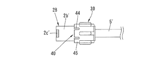
上記操作筒30の先端部内周は、環状の第2係合部形成領域40bとして提供される。詳述すると、操作筒30の先端部には、周方向に等間隔をおいてスリット44が形成されている。このスリット44は先端面から軸方向に所定長さD(図2)にわたって延びており、隣合うスリット44間が弾性変形部45となっている。弾性変形部45は、操作筒30の径方向に弾性変形可能である。各弾性変形部45の先端部内面には係合凸部46(第2係合部)が形成されている。この係合凸部46の軸方向寸法は、スリット44の長さDより小さく、弾性変形部45の弾性変形を容易にしている。
The inner periphery of the distal end portion of the
図3に示すように、第1係合部形成領域40aと第2係合部形成領域40bは径方向に対向しており、上記操作筒30に回転トルクが付与されていない状態では、係合凸部46が係合凹部41に入り込んでいる。
As shown in FIG. 3, the first engagement
図6Aに示すように、上記操作筒30の係合凸部46は、螺合緩み方向A側に,急峻な係止面46aを有し、螺合進み方向B側に緩やかな傾斜面46bを有している。
上記螺合部材20の係合凹部41は、その周方向一方側に、上記係合凸部46の係止面46aと周方向に対向する急峻な係止面41aを有し、周方向他方側に緩やかな傾斜面41bを有している。より具体的に説明すると、係止面41a、46aの周方向に対する角度は略90°と大きく、傾斜面41b,46bの周方向に対する角度は、約30〜40°と小さい。As shown in FIG. 6A, the engaging
The
上記構成をなす接続構造を用いてチューブ5、5’同士を接続する。図1Aに示すように雄型コネクタ1と雌型コネクタ2を同軸にして両者を互いに近づける。すると、図1Bに示すように雄型コネクタ1の雄型ルアー部14が雌型コネクタ2の雌型ルアー部2bの先端部に挿入される。
上記挿入は、上記雌型コネクタ2の突起2cが雄型コネクタ1の雌ねじ部22aの開口端の歯に当たるまで抵抗なく進められる。The
The insertion is proceeded without resistance until the
次に、操作筒30を図3、図6Aに示す螺合進み方向Bに回す。すると、図6Bに示すように、操作筒30の係合凸部46の傾斜面46bが、螺合部材20の係合凹部41の傾斜面41bに当たるため、操作筒30と一緒に螺合部材20が回る。これにより、雌型コネクタ2の突起2cと螺合部材20の雌ねじ部22aとの螺合が進む。螺合の初期は殆ど抵抗が無いため、小さな回転トルクで操作筒30と螺合部材20が一緒に回転されて螺合が進み、弾性変形部45の径方向外側への変形はわずかである。この螺合に伴い、雌型ルアー部2bは雄型ルアー部14と雌ねじ部22aの間の挿入空間に入り込む。
Next, the
上記螺合が進むと、上記雄型ルアー部14の雌型ルアー部2bへの挿入深さが増し、両者が接合して摩擦抵抗が増大する。その結果、操作筒30の回転に要するトルクが増大する。そのため、図6Cに示すように、操作筒30の係合凸部46の係合凹部41に対する周方向の相対変位が生じ、傾斜面41b、46bの作用により弾性変形部45の径方向外方向への弾性変形量が増大する。
As the screwing proceeds, the insertion depth of the
さらに螺合が進むと、上記操作筒30の回転トルクが所定トルクに達し、上記雄型ルアー部14と雌型ルアー部2bが良好なシール性能を発揮するのに十分な押圧力をもって接合する。この時には、図6Dに示すように、上記係合凸部46が係合凹部41から脱し、円弧面42を滑る。このようにして、操作筒30が空回りするため、操作筒30の回転トルクが螺合部材20に伝達されず、螺合部材20は回らなくなる。
As the screwing further proceeds, the rotational torque of the
上記のように操作筒30から螺合部材20に伝達される回転トルクの上限が所定トルクになるようにトルク管理を行うため、雄型ルアー部14と雌型ルアー部2bとの間の押圧力が過剰にならず十分なシール性能を発揮できるように管理することができる。その結果、液体を、チューブ5、通路15,2d、チューブ5’に沿って漏れることなく流すことができる。また過剰トルク付与による雄型ルアー部14や雌型ルアー部2bの破損を回避できる。
In order to perform torque management so that the upper limit of the rotational torque transmitted from the operating
上記のようにチューブ5、5’を接続した後、接続の解除が必要になった場合には、操作筒30を螺合緩み方向Aに回す。すると、操作筒30の係合凸部46の係止面46aが螺合部材20の係合凹部41の係止面41aに当たり、螺合部材20が操作筒30と一緒に螺合緩み方向に回る。その結果、雄型ルアー部14と雌型ルアー部2bの接合状態が解除され、やがてコネクタ1,2同士が分離される。
If it is necessary to release the connection after connecting the
上記のように螺合を緩める際、急峻な係止面41a,46aが当たるため、操作筒30は上記螺合を進める作業における上限トルクより大きなトルクを螺合部材20に付与することができ、確実に螺合を緩めることができる。
When the screwing is loosened as described above, since the
上述したように、雄型ルアー部14と雌型ルアー部2bは適度な押圧力で接合しているので、噛み付きを回避できる。そのため、螺合緩め作業の際に、過剰な回転トルクを必要とせず、雄型ルアー部14と雌型ルアー部2bに過剰なねじれ応力が作用しないので、これらルアー部14,2bの破損を回避でき、コネクタ1,2の各々は他のコネクタとの再接続作業も可能となる。
As described above, since the
上記操作筒30の係合凸部46は種々の形状を採用可能である。例えば図7Aに示すように、係合凸部46の周方向寸法を係合凹部41の周方向寸法の約半分程度にしてもよい。この場合、係合凸部46の傾斜面46bが係合凹部41の傾斜面41bの略中央部に当たってトルク伝達が行われる。また、図7B、図7Cに示すように、係合凸部46は傾斜面が無くてもよい。
なお、係合凸部46が傾斜面46bを有する場合、係合凹部41は傾斜面を有さなくてもよい。Various shapes can be adopted for the engaging
In addition, when the engagement
以下、本発明の他の実施形態を図面を参照しながら説明する。これら実施形態において先行して説明する実施形態に対応する構成については、同番号または類似番号を付してその詳細な説明を省略する。 Hereinafter, other embodiments of the present invention will be described with reference to the drawings. The configurations corresponding to the embodiments described earlier in these embodiments are given the same or similar numbers, and detailed descriptions thereof are omitted.
図8、図9に示す第2実施形態では、雄型コネクタ1の支持部22bの先端部外周の第1係合部形成領域40aに、その円筒面から突出する係合凸部47(第1係合部)が周方向に等間隔をなして形成されている。操作筒30の先端部内周の第2係合部形成領域40bには、係合凹部48(第2係合部)が周方向に等間隔をなして形成されている。具体的には、各弾性変形部45の内面に係合凹部48が形成されている。
第1実施形態と同様に、係合凸部47は係止面47aと傾斜面47bを有し、係合凹部48は係止面48aと傾斜面48bを有している。ただし、係止面47aと傾斜面47bは第1実施形態の係止面41a,傾斜面41bとは逆に配置され、係止面48aと傾斜面48bも第1実施形態の係止面46a,傾斜面46bと逆に配置されている。In the second embodiment shown in FIG. 8 and FIG. 9, the engagement convex portion 47 (the first projection) protruding from the cylindrical surface is formed in the first engagement
Similar to the first embodiment, the engaging
上記第2実施形態において、操作筒30を螺合進み方向B(図9参照)に回すと、操作筒30の係合凹部48の傾斜面48bが、螺合部材20の係合凸部47の傾斜面47bに当たるため、操作筒30と一緒に螺合部材20が回る。螺合が進んで操作筒30の回転に要するトルクが増大し、所定トルクに達すると、係合凹部48が係合凸部47から脱し、係合凸部47は弾性変形部45の円弧面を滑る。
In the second embodiment, when the
操作筒30を螺合緩み方向Aに回すと、操作筒30の係合凹部48の係止面48aが螺合部材20の係合凸部47の係止面47aに当たり、螺合部材20が操作筒30と一緒に螺合緩み方向に回る。
When the
第2実施形態において、図10A〜図10Cに示すように、係合凸部47の形状は種々変更可能である。これら係合凸部47の形状は、図7A〜図7Cに示す係合凸部46の形状にそれぞれ似ているので、説明を省略する。
なお、係合凸部47が傾斜面47bを有していれば、係合凹部48は傾斜面を有さなくてもよい。In 2nd Embodiment, as shown to FIG. 10A-FIG. 10C, the shape of the engagement
In addition, if the engagement
図11、図12に示す第3実施形態では、操作筒30の先端部に周方向に等間隔をおいてU字形のスリット44’が形成され、これらスリット44’に囲われた部位が径方向に弾性変形可能な弾性変形部45’として提供される。この弾性変形部45’の内面には第1実施形態と同様の係合凸部46が形成されている。他方、螺合部材20の支持部22bの外周には第1実施形態と同様の係合凹部41が形成されている。
In the third embodiment shown in FIGS. 11 and 12,
図13〜図16に示す第4実施形態では、操作筒30の基端側に第1実施形態と同様のトルクリミット機構40が配されている。詳述すると、上記操作筒30の基端部には、周方向に等間隔をおいてスリット44が形成されている。このスリット44は基端面から軸方向に所定長さにわたって延びており、隣り合うスリット44間が弾性変形部45となっている。各弾性変形部45の内面には係合凸部46が形成されている。他方、螺合部材20の支持部22bの基端部には、第1実施形態と同様の係合凹部41が周方向に等間隔をおいて形成されている。
In the fourth embodiment shown in FIGS. 13 to 16, a
螺合部材20の支持部22bには、上記係合凹部41に隣接した位置に、中心軸線と直交する環状の係止面26が形成されており、この係止面26に操作筒30の係合凸部46が係止されている。また、支持部22bの先端部には環状の凹部27が形成されており、この凹部27の奥端が中心軸線と直交する環状の係止面27aとなっている。この係止面27aに操作筒30の先端部内周から突出する係止凸部36が係止されている。その結果、操作筒30は螺合部材20に対して軸方向に移動不能となっている。
An
図17に示す第5実施形態の雄型コネクタ1A(第1接続部分)は、雌ねじ部22aと支持部22bを有する円筒部22が、雄型ルアー部14と一体をなしている。他の構成は第1実施形態と同様である。
In a
図18に示す第6実施形態では雄型コネクタ1A’は、第5実施形態の雄型コネクタ1Aと似た構成を有するボデイ51と、このボデイ51に回転可能に連結されたアタッチメント55とを有している。このアタッチメント55にチューブ5が固定される。
In the sixth embodiment shown in FIG. 18, the
図19〜図21に示す第7実施形態では、操作筒30が雌型コネクタ2Bに取り付けられている。したがって、雌型コネクタ2Bが第1接続部分として提供され、雌型ルアー部2b’が第1シール部として提供され、突起2c’が第1螺合部として提供される。また、雄型コネクタ1Bが第2接続部分として提供され、雄型ルアー部14’が第2シール部として提供され、雌ねじ部22a’が第2螺合部として提供される。
雄型コネクタ1Bは、操作筒30を取り付けるための構造を省き、螺合部材20の外周に指掛け部28を加えた点を除き、第1実施形態の雄型コネクタ1と同様の構成を有している。In the seventh embodiment shown in FIGS. 19 to 21, the
The
上記雌型コネクタ2Bの基端部外周が支持部2eとして提供される。上記操作筒30の先端部と雌型コネクタ2Bの支持部2eとの間にトルクリミット機構40が配置されている。詳述すると、雌型コネクタ2Bの支持部2eの第1係合部形成領域40aには、第1実施形態と同様に係合凹部41が周方向に等間隔をなして形成されている。操作筒30の先端部内周の第2係合部形成領域40bには、第1実施形態と同様に、スリット44、弾性変形部45、係合凸部46が形成されている。
The outer periphery of the base end portion of the
図19Aに示すように、操作筒30の基端部には周方向に等しい間隔をおいて径方向内側に突出する係合凸部38が形成されており、この係合凸部38が雌型コネクタ2Bの基端に形成された環状の係合溝2gに嵌ることにより、操作筒30は雌型コネクタ2Bに回転可能かつ軸方向移動不能に取り付けられている。
操作筒30に回転トルクが付与されていない状態では、操作筒30の係合凸部46が雌型コネクタ2Bの係合凹部41に入り込んでいる。As shown in FIG. 19A, an engagement convex portion 38 that protrudes radially inward at equal intervals in the circumferential direction is formed at the proximal end portion of the
In a state where no rotational torque is applied to the
図19Aに示すように雄型コネクタ1Bと雌型コネクタ2Bを同軸をなして互いに近づけ、図19Bに示すように突起2c’を雌ねじ部22a’の開口端に当てるとともに、雄型コネクタ1Bの雄型ルアー部14’を雌型コネクタ2Bの雌型ルアー部2b’の先端部に挿入する。
As shown in FIG. 19A, the
次に操作筒30を回すと、図19Cに示すように突起2c’と雌ねじ部22a’の螺合が進み、上記雄型ルアー部14’の雌型ルアー部2b’への挿入深さが増す。雄型ルアー部14’と雌型ルアー部2b’が接合して押圧力が増すと、両者の摩擦抵抗により操作筒30の回転に要するトルクが増大するが、前述したようにトルクリミット機構40により回転トルクを制限できる。
Next, when the
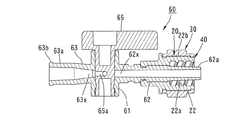
図22、図23に示す第8実施形態は、本発明を三方活栓60(活栓)に適用したものである。この三方活栓60は、筒形状をなすボデイ61と、このボデイ61に一体に形成された3つの流通管部を有している。1つの流通管部62は、その先端部に雄型ルアー部62a(第1シール部)を有し、第1実施形態と同様の螺合部材20と協働して第1接続部分を提供している。第1実施形態と同様に、螺合部材20には操作筒30が設けられ、螺合部材20と操作筒30との間にはトルクリミット機構40が配置されている。
他の2つの流通管部63,63の先端部には雌型ルアー部63a、63aと突起63bが形成されている。In the eighth embodiment shown in FIGS. 22 and 23, the present invention is applied to a three-way stopcock 60 (stopcock). The three-
上記ボデイ61には栓部材65が収容されている。この栓部材65はL字形をなす連通路65aを有し、回動操作により流通管部62,63,63の通路62x、63x、63xのうち2つを選択的に連通させるようになっている。
A
上記流通管部62に、例えば図1Aに示すチューブ5’に固定された雌型コネクタ2が接続される。接続作業の際の操作筒30、トルクリミット機構40の作用は第1実施形態と同様であるので説明を省略する。
なお、上記流通管部63を第2接続部分として提供し、この流通管部63に第1実施形態と同様の雄型コネクタ1を接続してもよい。For example, the
In addition, the said
図24、図25に示す第9実施形態は、第8実施形態と同様に三方活栓60に本発明を適用したものである。三方活栓60の流通管部63’が第1接続部分として提供され、流通管部63’の雌型ルアー部63a’が第1シール部として提供され、突起63b’が第1螺合部として提供される。雌型ルアー部63a’より基端側の部位が、操作筒30を支持する支持部として提供される。
上記流通管部63’に、例えば図19Aに示すチューブ5に固定された雄型コネクタ1Bが接続される。接続作業の際の操作筒30、トルクリミット機構40の作用は第7実施形態と同様であるので説明を省略する。
なお、上記流通管部62’と螺合部材20が協働して、図19Aに示す雄型コネクタ2Bと同様の構成をなす第2接続部分として提供される場合には、図19Aに示す雌型コネクタ2Bが接続される。In the ninth embodiment shown in FIGS. 24 and 25, the present invention is applied to a three-
For example, a
When the
図26〜図28に示す第10実施形態は、本発明を造影剤シリンジ70に適用したものである。このシリンジ70は液流出部71を有している。この液流出部71は第2接続部分として提供され、その先端部に上記雄型ルアー部72(第2シール部)を有し、この雄型ルアー部72よりシリンジ70の胴部70a側の外周に、雄ねじ部73(第2螺合部)を有している。液流出部71は、その中心軸線に沿って、上記胴部70aの内部空間に連なる通路74を有している。
In the tenth embodiment shown in FIGS. 26 to 28, the present invention is applied to a
上記シリンジ70の雄型ルアー部72には、例えばチューブ5’の端に固定された雌型ルアー部材2Cが、筒形状のアタッチメント75を介して接続される。この雌型ルアー部材2Cとアタッチメント75により第1接続部分が構成される。
アタッチメント75はその基端部に収容凹部76を有し、この収容凹部76には、雌型ルアー部材2Cの先端部の突起2c”が径方向から着脱可能に収容されるようになっている。For example, a
The
上記アタッチメント75は円筒部77を有し、この円筒部77の内周には雌ねじ部77a(第1螺合部)が形成されている。この円筒部77の外周は支持部77bとして提供され、この支持部77bには操作筒30が回転可能かつ軸方向移動不能に取り付けられている。この操作筒30の取付構造およびトルクリミット機構40は、第1実施形態と同様であるので詳細な説明を省略する。
The
雌型ルアー部材2Cをアタッチメント75に着脱可能に連結した状態で、操作筒30に回転トルクを付与してアタッチメント75の雌ねじ部77aと液流出部71の雄ねじ部73の螺合を進めることにより、雄型ルアー部72と雌型ルアー部2b”(第1シール部)とを接合する。この接続作業の際のトルクリミット機構40によるトルク管理は前述の全ての実施形態と同様である。
なお、上記シリンジ70の液流出部71に、第1実施形態と同様にして螺合部材20および操作筒30、トルクリミット機構40を装着し、この液流出部71に第1実施形態の雌型コネクタ2を接続してもよい、In a state where the
In addition, the screwing
図29、図30に示す第11実施形態は、本発明を通路閉塞構造に適用したものである。雄型閉塞部材80(第1接続部分)は、雄型ルアー部81(第1シール部)と円筒部82を一体に有している。雄型ルアー部81の通路81aは基端側で塞がれている。円筒部82は内周に雌ねじ部82a(第1螺合部)を有しており、その外周は、操作筒30を取り付けるための支持部82bとして提供される。この操作筒30の取付構造およびトルクリミット機構40は、第1実施形態と同様であるので詳細な説明を省略する。
The eleventh embodiment shown in FIGS. 29 and 30 is an application of the present invention to a passage closing structure. The male closing member 80 (first connection portion) integrally includes a male luer portion 81 (first seal portion) and a
上記雄型閉塞部材80は、雌型ルアー部、例えば三方活栓60の流通管部63(第2接続部分)に接続される。操作筒30を回して、雄型閉塞部材80の雌ねじ部82aと突起63b(第2螺合部)の螺合を進め、雄型ルアー部81と雌型ルアー部63a(第2シール部)を接合することにより、流通管部63の通路63xが閉塞される。
The
図31,図32に示す第12実施形態も、本発明を通路閉塞構造に適用したものである。
雌型閉塞部材85(第1接続部分)は、先端側に雌型ルアー部86(第1シール部)を有し、この雌型ルアー部86の先端外周に突起87(第1螺合部)が形成されている。さらに雌型閉塞部材85は、その基端側に操作筒30を取り付けるための支持部88を有している。この操作筒30の取付構造およびトルクリミット機構40は、第7実施形態(図19参照)と同様であるので詳細な説明を省略する。雌型ルアー部86の通路86aは基端側で塞がれている。The twelfth embodiment shown in FIGS. 31 and 32 also applies the present invention to a passage closing structure.
The female closing member 85 (first connecting portion) has a female luer portion 86 (first seal portion) on the distal end side, and a protrusion 87 (first screwing portion) on the outer periphery of the distal end of the
上記雌型閉塞部材85は、例えば三方活栓60の流通管部62’(第2接続部分)に接続される。操作筒30を回して、雌型閉塞部材85の突起87と流通管部62’に設けられた螺合部材20の雌ねじ部22a’(第2螺合部)との螺合を進め、流通管部62’の雄型ルアー部62a’(第2シール部)と雌型ルアー部86を接合することにより、流通管部62’の通路62x’が閉塞される。
The
図1〜図6に示す第1実施形態において、コネクタ2の通路2dの基端を塞ぐことにより雌型閉塞部材を構成してもよい。
図19〜図21に示す第7実施形態において、コネクタ1Bの通路15の基端を塞ぐことにより雄型閉塞部材を構成してもよい。In 1st Embodiment shown in FIGS. 1-6, you may comprise a female type | mold obstruction | occlusion member by plugging up the base end of the channel |
In the seventh embodiment shown in FIGS. 19 to 21, the male closing member may be configured by closing the proximal end of the
本発明は上記実施形態に制約されず、種々の態様が可能である。上述した多数の実施形態の各々の特徴は、他の実施形態の特徴と組み合わせることも可能である。
本発明は、チューブ、活栓、シリンジ以外の医療用構成要素での接続構造に適用してもよい。
上記実施形態では、第1接続部分と操作筒は、第1係合部、第2係合部をそれぞれ複数有しているが、それぞれ1つであってもよい。
操作筒の第2接続部分の螺合部に対する回動は相対的なものであり、操作筒を静止させて第2部分の螺合部を回すようにしてもよい。The present invention is not limited to the above-described embodiments, and various aspects are possible. The features of each of the numerous embodiments described above can be combined with the features of other embodiments.
You may apply this invention to the connection structure in medical components other than a tube, a stopcock, and a syringe.
In the above-described embodiment, the first connection portion and the operation cylinder each have a plurality of first engagement portions and second engagement portions, but may each be one.
The rotation of the second connecting portion of the operation tube relative to the screwing portion is relative, and the operation tube may be stationary and the screwing portion of the second portion may be rotated.
本発明は、チューブ、活栓、シリンジ等の医療構成要素のための接続構造に適用することができる。 The present invention can be applied to connection structures for medical components such as tubes, stopcocks, and syringes.
Claims (7)
上記第1接続部分と上記第2接続部分が、互いに螺合する第1螺合部(22a;2c’;63b’;77a;82a;87)と第2螺合部(2c;22a’;63b;73)をそれぞれ有するとともに、この螺合を進めることにより互いに接合する第1シール部(14;2b’;2b”;62a;63a’;81;86)と第2シール部(2b;14’;62a’;63a;72)をそれぞれ有し、
上記第1シール部と第2シール部の一方は外周がテーパをなす雄型ルアー部であり、他方は内周がテーパをなす雌型ルアー部であり、上記雄型ルアー部の外周と上記雌型ルアー部の内周が接合することにより、上記雄型ルアー部と上記雌型ルアー部との間がシールされる医療用接続構造において、
上記第1接続部分(1;1A;1A’;2B;2C;62;63’;80;85)は、上記第1螺合部(22a;2c’;63b’;77a;82a;87)と一体をなす支持部(22b;2e;77b;82b;88)を有し、この支持部の外周に操作筒(30)が軸方向移動不能に取り付けられ、これら第1接続部分の支持部と操作筒との間にトルクリミット機構(40)が設けられ、このトルクリミット機構は、
(ア)上記操作筒を上記第2接続部分に対して螺合緩み方向に回した時には、上記操作筒と一緒に上記第1接続部分の上記支持部が回り、
(イ)上記操作筒を上記第2接続部分に対して螺合進み方向に回す過程において、上記操作筒に付与される回転トルクが所定トルクに達するまで、上記操作筒と一緒に上記第1接続部分の上記支持部が回り、
(ウ)上記操作筒を上記第2接続部分に対して螺合進み方向に回す過程において、上記第1シール部と第2シール部の接合により生じる抵抗を受けて上記操作筒の回転トルクが所定トルクに達した時には、上記操作筒が上記第1接続部分の上記支持部に対して空回りする
ように構成されており、
上記支持部の外周と上記操作筒の内周は、互いに径方向に対向する環状の第1係合部形成領域(40a)と第2係合部形成領域(40b)をそれぞれ有し、
上記操作筒(30)の軸方向一端部の内周が上記第2係合部形成領域として提供され、当該一端部には、軸方向に延びる複数のスリット(44)が周方向に等間隔をおいて形成され、上記スリット間の部位が複数の弾性変形部(45)として提供され、これら複数の弾性変形部は互いに独立して径方向に弾性変形可能であり、
上記トルクリミット機構(40)は、上記第1係合部形成領域(40a)に周方向に等間隔をおいて形成された複数の第1係合部(41;47)と、上記複数の弾性変形部(45)の内面に形成された第2係合部(46;48)とを有し、
上記第2係合部(46;48)の一方側と上記第1係合部(41;47)の一方側が急峻な係止面(46a,41a;48a,47a)をそれぞれ有し、上記第2係合部の上記他方側と上記第1係合部の上記他方側の少なくとも一方が、傾斜面(46b,41b;48b,47b)を有し、
上記操作筒を上記第2接続部分に対して螺合緩み方向に回した時には、上記第2係合部(46;48)の一方側の係止面(46a,48a)がこれと周方向に対向する上記第1係合部(41;47)の一方側の係止面(41a;47a)に係止されることにより、上記操作筒と一緒に上記第1接続部分の上記支持部が回り、
上記操作筒を上記第2接続部分に対して螺合進み方向に回す過程において、上記第2係合部(46;48)の他方側が上記第1係合部(41;47)の他方側に係止されることにより、上記操作筒に付与される回転トルクが所定トルクに達するまで、上記操作筒と一緒に上記第1接続部分の上記支持部が回り、
上記操作筒を上記第2接続部分に対して螺合進み方向に回す過程において、上記第1シール部と第2シール部の接合により生じる抵抗を受けて上記操作筒の回転トルクが所定トルクに達した時には、上記弾性変形部(45)の径方向外方向の弾性変形を伴って上記第2係合部(46;48)が上記第1係合部(41;47)を超えることにより、上記操作筒が空回りすることを特徴とする医療用接続構造。 A first connecting portion (1; 1A; 1A ';2B;2C;62;63';80; 85) and a second connecting portion (2; 1B; 62 ';63;71);
A first screwing portion (22a; 2c ′; 63b ′; 77a; 82a; 87) and a second screwing portion (2c; 22a ′; 63b) in which the first connection portion and the second connection portion are screwed together. 73) and the first seal portion (14; 2b ′; 2b ″; 62a; 63a ′; 81; 86) and the second seal portion (2b; 14 ′) that are joined together by advancing this screwing. 62a ′; 63a; 72) respectively;
One of the first seal portion and the second seal portion is a male luer portion whose outer periphery is tapered, and the other is a female luer portion whose inner periphery is tapered, the outer periphery of the male luer portion and the female luer portion In the medical connection structure in which the gap between the male luer part and the female luer part is sealed by joining the inner periphery of the mold luer part.
The first connecting portion (1; 1A; 1A ′; 2B; 2C; 62; 63 ′; 80; 85) is connected to the first threaded portion (22a; 2c ′; 63b ′; 77a; 82a; 87). It has a support part (22b; 2e; 77b; 82b; 88) that is integrated, and an operation cylinder (30) is attached to the outer periphery of this support part so as not to move in the axial direction. A torque limit mechanism (40) is provided between the cylinder and this torque limit mechanism.
(A) When the operation tube is rotated in the screwing loosening direction with respect to the second connection portion, the support portion of the first connection portion rotates together with the operation tube,
(A) In the process of turning the operation cylinder in the threading advance direction with respect to the second connection portion, the first connection together with the operation cylinder until the rotational torque applied to the operation cylinder reaches a predetermined torque. The above support part of the part turns,
(C) In the process of turning the operation cylinder in the threading advance direction with respect to the second connection portion, the rotational torque of the operation cylinder is predetermined by receiving resistance generated by joining the first seal portion and the second seal portion. When the torque is reached, the operation cylinder is configured to idle with respect to the support portion of the first connection portion ,
The outer periphery of the support part and the inner periphery of the operation cylinder have an annular first engaging part forming region (40a) and a second engaging part forming region (40b) that are opposed to each other in the radial direction,
An inner periphery of one end portion in the axial direction of the operation cylinder (30) is provided as the second engaging portion forming region, and a plurality of slits (44) extending in the axial direction are equidistant from the one end portion in the circumferential direction. The portions between the slits are provided as a plurality of elastic deformation portions (45), and the plurality of elastic deformation portions can be elastically deformed in the radial direction independently of each other,
The torque limit mechanism (40) includes a plurality of first engagement portions (41; 47) formed at equal intervals in the circumferential direction in the first engagement portion formation region (40a), and the plurality of elasticities. A second engagement portion (46; 48) formed on the inner surface of the deformation portion (45),
One side of the second engaging portion (46; 48) and one side of the first engaging portion (41; 47) have steep locking surfaces (46a, 41a; 48a, 47a), respectively. At least one of the other side of the two engaging portions and the other side of the first engaging portion has an inclined surface (46b, 41b; 48b, 47b);
When the operation cylinder is rotated in the screwing loosening direction with respect to the second connection portion, the locking surface (46a, 48a) on one side of the second engagement portion (46; 48) is in the circumferential direction. By being locked to one locking surface (41a; 47a) of the opposing first engaging portion (41; 47), the support portion of the first connection portion rotates together with the operation cylinder. ,
In the process of turning the operation cylinder in the screwing advance direction with respect to the second connection portion, the other side of the second engagement portion (46; 48) is brought to the other side of the first engagement portion (41; 47). By being locked, the support portion of the first connection portion rotates together with the operation cylinder until the rotational torque applied to the operation cylinder reaches a predetermined torque,
In the process of turning the operation cylinder in the threading advance direction with respect to the second connection portion, the rotational torque of the operation cylinder reaches a predetermined torque due to the resistance generated by the joining of the first seal portion and the second seal portion. When the second engaging portion (46; 48) exceeds the first engaging portion (41; 47) with the elastic deformation in the radially outward direction of the elastic deforming portion (45), medical connecting structure, wherein the operation tube runs idle.
上記第1接続部分と上記第2接続部分が、互いに螺合する第1螺合部(22a;2c’;63b’;77a;82a;87)と第2螺合部(2c;22a’;63b;73)をそれぞれ有するとともに、この螺合を進めることにより互いに接合する第1シール部(14;2b’;2b”;62a;63a’;81;86)と第2シール部(2b;14’;62a’;63a;72)をそれぞれ有し、
上記第1シール部と第2シール部の一方は外周がテーパをなす雄型ルアー部であり、他方は内周がテーパをなす雌型ルアー部であり、上記雄型ルアー部の外周と上記雌型ルアー部の内周が接合することにより、上記雄型ルアー部と上記雌型ルアー部との間がシールされる医療用接続構造において、
上記第1接続部分(1;1A;1A’;2B;2C;62;63’;80;85)は、上記第1螺合部(22a;2c’;63b’;77a;82a;87)と一体をなす支持部(22b;2e;77b;82b;88)を有し、この支持部の外周に操作筒(30)が軸方向移動不能に取り付けられ、これら第1接続部分の支持部と操作筒との間にトルクリミット機構(40)が設けられ、このトルクリミット機構は、
(ア)上記操作筒を上記第2接続部分に対して螺合緩み方向に回した時には、上記操作筒と一緒に上記第1接続部分の上記支持部が回り、
(イ)上記操作筒を上記第2接続部分に対して螺合進み方向に回す過程において、上記操作筒に付与される回転トルクが所定トルクに達するまで、上記操作筒と一緒に上記第1接続部分の上記支持部が回り、
(ウ)上記操作筒を上記第2接続部分に対して螺合進み方向に回す過程において、上記第1シール部と第2シール部の接合により生じる抵抗を受けて上記操作筒の回転トルクが所定トルクに達した時には、上記操作筒が上記第1接続部分の上記支持部に対して空回りする
ように構成されており、
上記支持部の外周と上記操作筒の内周は、互いに径方向に対向する環状の第1係合部形成領域(40a)と第2係合部形成領域(40b)をそれぞれ有し、
上記操作筒(30)において上記第2係合部形成領域に対応する部位には、U字形状をなす複数のスリット(44’)が周方向に等間隔をおいて形成され、これらスリットにより囲われた部位が弾性変形部(45’)として提供され、
上記トルクリミット機構(40)は、上記第1係合部形成領域(40a)に周方向に等間隔をおいて形成された複数の第1係合部(41;47)と、上記複数の弾性変形部(45’)の内面に形成された第2係合部(46;48)とを有し、
上記第2係合部(46;48)の一方側と上記第1係合部(41;47)の一方側が急峻な係止面(46a,41a;48a,47a)をそれぞれ有し、上記第2係合部の上記他方側と上記第1係合部の上記他方側の少なくとも一方が、傾斜面(46b,41b;48b,47b)を有し、
上記操作筒を上記第2接続部分に対して螺合緩み方向に回した時には、上記第2係合部(46;48)の一方側の係止面(46a,48a)がこれと周方向に対向する上記第1係合部(41;47)の一方側の係止面(41a;47a)に係止されることにより、上記操作筒と一緒に上記第1接続部分の上記支持部が回り、
上記操作筒を上記第2接続部分に対して螺合進み方向に回す過程において、上記第2係合部(46;48)の他方側が上記第1係合部(41;47)の他方側に係止されることにより、上記操作筒に付与される回転トルクが所定トルクに達するまで、上記操作筒と一緒に上記第1接続部分の上記支持部が回り、
上記操作筒を上記第2接続部分に対して螺合進み方向に回す過程において、上記第1シール部と第2シール部の接合により生じる抵抗を受けて上記操作筒の回転トルクが所定トルクに達した時には、上記弾性変形部(45’)の弾性変形を伴って上記第2係合部(46;48)が上記第1係合部(41;47)を超えることにより、上記操作筒が空回りすることを特徴とする医療用接続構造。 A first connecting portion (1; 1A; 1A ';2B;2C;62;63';80; 85) and a second connecting portion (2; 1B; 62 ';63;71);
A first screwing portion (22a; 2c ′; 63b ′; 77a; 82a; 87) and a second screwing portion (2c; 22a ′; 63b) in which the first connection portion and the second connection portion are screwed together. 73) and the first seal portion (14; 2b ′; 2b ″; 62a; 63a ′; 81; 86) and the second seal portion (2b; 14 ′) that are joined together by advancing this screwing. 62a ′; 63a; 72) respectively;
One of the first seal portion and the second seal portion is a male luer portion whose outer periphery is tapered, and the other is a female luer portion whose inner periphery is tapered, the outer periphery of the male luer portion and the female luer portion In the medical connection structure in which the gap between the male luer part and the female luer part is sealed by joining the inner periphery of the mold luer part.
The first connecting portion (1; 1A; 1A ′; 2B; 2C; 62; 63 ′; 80; 85) is connected to the first threaded portion (22a; 2c ′; 63b ′; 77a; 82a; 87). It has a support part (22b; 2e; 77b; 82b; 88) that is integrated, and an operation cylinder (30) is attached to the outer periphery of this support part so as not to move in the axial direction. A torque limit mechanism (40) is provided between the cylinder and this torque limit mechanism.
(A) When the operation tube is rotated in the screwing loosening direction with respect to the second connection portion, the support portion of the first connection portion rotates together with the operation tube,
(A) In the process of turning the operation cylinder in the threading advance direction with respect to the second connection portion, the first connection together with the operation cylinder until the rotational torque applied to the operation cylinder reaches a predetermined torque. The above support part of the part turns,
(C) In the process of turning the operation cylinder in the threading advance direction with respect to the second connection portion, the rotational torque of the operation cylinder is predetermined by receiving resistance generated by joining the first seal portion and the second seal portion. When the torque is reached, the operation cylinder is configured to idle with respect to the support portion of the first connection portion ,
The outer periphery of the support part and the inner periphery of the operation cylinder have an annular first engaging part forming region (40a) and a second engaging part forming region (40b) that are opposed to each other in the radial direction,
A plurality of U-shaped slits (44 ′) are formed at equal intervals in the circumferential direction at a portion corresponding to the second engagement portion formation region in the operation cylinder (30), and are surrounded by the slits. The broken part is provided as an elastic deformation part (45 ′),
The torque limit mechanism (40) includes a plurality of first engagement portions (41; 47) formed at equal intervals in the circumferential direction in the first engagement portion formation region (40a), and the plurality of elasticities. A second engaging portion (46; 48) formed on the inner surface of the deformable portion (45 ′),
One side of the second engaging portion (46; 48) and one side of the first engaging portion (41; 47) have steep locking surfaces (46a, 41a; 48a, 47a), respectively. At least one of the other side of the two engaging portions and the other side of the first engaging portion has an inclined surface (46b, 41b; 48b, 47b);
When the operation cylinder is rotated in the screwing loosening direction with respect to the second connection portion, the locking surface (46a, 48a) on one side of the second engagement portion (46; 48) is in the circumferential direction. By being locked to one locking surface (41a; 47a) of the opposing first engaging portion (41; 47), the support portion of the first connection portion rotates together with the operation cylinder. ,
In the process of turning the operation cylinder in the screwing advance direction with respect to the second connection portion, the other side of the second engagement portion (46; 48) is brought to the other side of the first engagement portion (41; 47). By being locked, the support portion of the first connection portion rotates together with the operation cylinder until the rotational torque applied to the operation cylinder reaches a predetermined torque,
In the process of turning the operation cylinder in the threading advance direction with respect to the second connection portion, the rotational torque of the operation cylinder reaches a predetermined torque due to the resistance generated by the joining of the first seal portion and the second seal portion. In this case, the second engaging portion (46; 48) exceeds the first engaging portion (41; 47) with the elastic deformation of the elastic deforming portion (45 ′), so that the operation cylinder is idled. A medical connection structure characterized by:
上記操作筒(30)の上記第2係合部形成領域(40b)には、上記第2係合部としての係合凸部(46)が形成され、上記操作筒に回転トルクが付与されない状態において、上記係合凸部が上記係合凹部に収容されていることを特徴とする請求項1〜3のいずれかに記載の医療用接続構造。 An engagement recess (41) as the first engagement portion is formed in the first engagement portion formation region (40a) of the support portion (22b).
In the second engagement portion forming region (40b) of the operation tube (30), an engagement convex portion (46) as the second engagement portion is formed, and no rotational torque is applied to the operation tube. The medical connection structure according to claim 1, wherein the engaging convex portion is accommodated in the engaging concave portion.
上記操作筒(30)の上記第2係合部形成領域(40b)には、上記第2係合部としての係合凹部(48)が形成され、上記操作筒に回転トルクが付与されない状態において、上記係合凸部が上記係合凹部に収容されていることを特徴とする請求項1〜3のいずれかに記載の医療用接続構造。 An engagement convex portion (47) as the first engagement portion is formed in the first engagement portion formation region (40a) of the support portion (22b).
In the second engagement portion formation region (40b) of the operation cylinder (30), an engagement recess (48) as the second engagement portion is formed, and in a state where no rotational torque is applied to the operation cylinder. The medical connection structure according to any one of claims 1 to 3, wherein the engaging convex portion is accommodated in the engaging concave portion.
Applications Claiming Priority (3)
| Application Number | Priority Date | Filing Date | Title |
|---|---|---|---|
| JP2015075582 | 2015-04-02 | ||
| JP2015075582 | 2015-04-02 | ||
| PCT/JP2016/052474 WO2016157974A1 (en) | 2015-04-02 | 2016-01-28 | Medical connection structure |
Publications (2)
| Publication Number | Publication Date |
|---|---|
| JPWO2016157974A1 JPWO2016157974A1 (en) | 2018-01-18 |
| JP6468678B2 true JP6468678B2 (en) | 2019-02-13 |
Family
ID=57004140
Family Applications (1)
| Application Number | Title | Priority Date | Filing Date |
|---|---|---|---|
| JP2016536789A Active JP6468678B2 (en) | 2015-04-02 | 2016-01-28 | Medical connection structure |
Country Status (5)
| Country | Link |
|---|---|
| US (1) | US10183158B2 (en) |
| EP (1) | EP3108926B1 (en) |
| JP (1) | JP6468678B2 (en) |
| CN (1) | CN106232173B (en) |
| WO (1) | WO2016157974A1 (en) |
Families Citing this family (13)
| Publication number | Priority date | Publication date | Assignee | Title |
|---|---|---|---|---|
| JP6707075B2 (en) * | 2015-03-11 | 2020-06-10 | テルモ株式会社 | Connector and medical device set |
| WO2018142902A1 (en) * | 2017-02-01 | 2018-08-09 | テルモ株式会社 | Connector |
| JP6462900B1 (en) * | 2017-04-12 | 2019-01-30 | 光陽産業株式会社 | Medical connection structure |
| JP6946749B2 (en) * | 2017-05-30 | 2021-10-06 | 株式会社ジェイ・エム・エス | Female connector |
| DE102018104457A1 (en) * | 2018-02-27 | 2019-08-29 | B. Braun Avitum Ag | Connection unit for a blood treatment machine for connecting the blood treatment machine to an external container and blood treatment machine with such a connection unit |
| SG11202011101YA (en) | 2018-05-18 | 2020-12-30 | Bard Peripheral Vascular Inc | Systems and methods for use of a dosimetry application software tool to customize dosimetry and sphere selection for radioembolization procedure planning |
| CN112312958A (en) * | 2018-05-18 | 2021-02-02 | 巴德外周血管股份有限公司 | Connector assembly |
| JP6599528B2 (en) * | 2018-09-10 | 2019-10-30 | 光陽産業株式会社 | Medical connection structure |
| JP6918324B2 (en) * | 2018-10-04 | 2021-08-11 | 光陽産業株式会社 | Medical connection structure |
| IT201900012735A1 (en) * | 2019-07-24 | 2021-01-24 | Gvs Spa | Improved three-way connector |
| EP3827803B1 (en) * | 2019-11-28 | 2023-06-07 | Axium MTech SA | Medical connector |
| CN215741358U (en) * | 2020-07-10 | 2022-02-08 | 苏州医本生命科技有限公司 | Gas-liquid conveying joint, gas-liquid conveying joint pair and gas-liquid conveying device |
| JP2022117856A (en) * | 2021-02-01 | 2022-08-12 | 株式会社ジェイ・エム・エス | medical connector |
Family Cites Families (17)
| Publication number | Priority date | Publication date | Assignee | Title |
|---|---|---|---|---|
| JPS62116740U (en) | 1986-01-17 | 1987-07-24 | ||
| US5520666A (en) * | 1994-12-06 | 1996-05-28 | Abbott Laboratories | Valved intravenous fluid line connector |
| US5620427A (en) * | 1995-04-27 | 1997-04-15 | David R. Kipp | Luer lock system |
| JP2001187990A (en) * | 1999-12-28 | 2001-07-10 | Ookisu:Kk | Medical connecting member |
| US7316679B2 (en) * | 2001-01-22 | 2008-01-08 | Venetec International, Inc. | Medical device connector fitting |
| DE20109061U1 (en) * | 2001-05-31 | 2001-08-09 | Braun Melsungen Ag | Patient safety connector |
| JP3108468U (en) | 2004-10-29 | 2005-04-14 | 川澄化学工業株式会社 | Connecting member and medical device |
| US8852167B2 (en) * | 2005-12-01 | 2014-10-07 | Bayer Medical Care Inc. | Medical connector |
| JP4686674B2 (en) | 2006-05-22 | 2011-05-25 | 丸一株式会社 | Tightening nut |
| JP2008005974A (en) * | 2006-06-28 | 2008-01-17 | Nippon Sherwood Medical Industries Ltd | Lure fixing, fitting and connecting structure |
| US7857805B2 (en) * | 2006-10-02 | 2010-12-28 | B. Braun Medical Inc. | Ratcheting luer lock connector |
| US20100036329A1 (en) * | 2008-08-07 | 2010-02-11 | Nasser Razack | Hemostasis valve |
| US8882726B2 (en) | 2010-03-10 | 2014-11-11 | Becton Dickinson France | Drug delivery device with safe connection means |
| US8465322B2 (en) * | 2011-03-25 | 2013-06-18 | Ppc Broadband, Inc. | Coaxial cable connector |
| US8777931B2 (en) * | 2011-08-19 | 2014-07-15 | Alcon Research, Ltd. | Retractable luer lock fittings |
| JP6001903B2 (en) | 2012-03-30 | 2016-10-05 | 大研医器株式会社 | Connecting member |
| PT2677224T (en) * | 2012-06-20 | 2016-07-15 | Fischer Georg Jrg Ag | Clamp connection for pipes |
-
2016
- 2016-01-28 JP JP2016536789A patent/JP6468678B2/en active Active
- 2016-01-28 EP EP16730235.5A patent/EP3108926B1/en active Active
- 2016-01-28 WO PCT/JP2016/052474 patent/WO2016157974A1/en active Application Filing
- 2016-01-28 CN CN201680000554.9A patent/CN106232173B/en active Active
- 2016-01-28 US US15/102,557 patent/US10183158B2/en active Active
Also Published As
| Publication number | Publication date |
|---|---|
| EP3108926A1 (en) | 2016-12-28 |
| US10183158B2 (en) | 2019-01-22 |
| JPWO2016157974A1 (en) | 2018-01-18 |
| CN106232173A (en) | 2016-12-14 |
| US20170120032A1 (en) | 2017-05-04 |
| CN106232173B (en) | 2019-08-30 |
| EP3108926B1 (en) | 2020-04-15 |
| WO2016157974A1 (en) | 2016-10-06 |
| EP3108926A4 (en) | 2018-01-24 |
Similar Documents
| Publication | Publication Date | Title |
|---|---|---|
| JP6468678B2 (en) | Medical connection structure | |
| US7347458B2 (en) | Locking luer fitting | |
| JPWO2018189842A1 (en) | Medical connection structure | |
| JP7020724B2 (en) | Male medical connection device | |
| JP2016508200A (en) | Concatenation system and concatenation method | |
| US10299993B2 (en) | Valve assembly and methods of use | |
| EP3004711A1 (en) | Connector for medical lines | |
| WO2012077549A1 (en) | Hose connector and joint structure for shower hose | |
| JP2592358B2 (en) | Pipe fittings | |
| JP2004092903A (en) | Pipe connector | |
| JP2010213780A (en) | Fixture, joint member, and medical equipment | |
| US20180008813A1 (en) | Medical connector | |
| JP6268877B2 (en) | Medical connector | |
| JP2008256012A (en) | Joint for synthetic resin fluid pipe | |
| JP5845020B2 (en) | Pipe fitting | |
| JP2008029606A (en) | Medical tube joint and line for use in infusion or blood transfer using the same | |
| JP2017214992A (en) | Hose joint | |
| WO2022163311A1 (en) | Medical connector | |
| US20230045573A1 (en) | Medical connectors | |
| JP6599528B2 (en) | Medical connection structure | |
| KR200473400Y1 (en) | Apparatus for connecting a pipe and a connecting pipe | |
| JP2023071573A (en) | Medical connection device | |
| KR200424499Y1 (en) | Hose connector having preventing disconnect | |
| KR101671919B1 (en) | Connecting structure of universal joint | |
| JP2015058198A (en) | Pre-filled syringe |
Legal Events
| Date | Code | Title | Description |
|---|---|---|---|
| A621 | Written request for application examination |
Free format text: JAPANESE INTERMEDIATE CODE: A621 Effective date: 20171102 |
|
| A131 | Notification of reasons for refusal |
Free format text: JAPANESE INTERMEDIATE CODE: A131 Effective date: 20180605 |
|
| A521 | Request for written amendment filed |
Free format text: JAPANESE INTERMEDIATE CODE: A523 Effective date: 20180629 |
|
| A131 | Notification of reasons for refusal |
Free format text: JAPANESE INTERMEDIATE CODE: A131 Effective date: 20180911 |
|
| A521 | Request for written amendment filed |
Free format text: JAPANESE INTERMEDIATE CODE: A523 Effective date: 20180914 |
|
| TRDD | Decision of grant or rejection written | ||
| A01 | Written decision to grant a patent or to grant a registration (utility model) |
Free format text: JAPANESE INTERMEDIATE CODE: A01 Effective date: 20190108 |
|
| A61 | First payment of annual fees (during grant procedure) |
Free format text: JAPANESE INTERMEDIATE CODE: A61 Effective date: 20190112 |
|
| R150 | Certificate of patent or registration of utility model |
Ref document number: 6468678 Country of ref document: JP Free format text: JAPANESE INTERMEDIATE CODE: R150 |
|
| R250 | Receipt of annual fees |
Free format text: JAPANESE INTERMEDIATE CODE: R250 |