EP2731215A1 - Kabelführungseinrichtung zur Verwendung bei der Installation von Kabeln - Google Patents
Kabelführungseinrichtung zur Verwendung bei der Installation von Kabeln Download PDFInfo
- Publication number
- EP2731215A1 EP2731215A1 EP20130004810 EP13004810A EP2731215A1 EP 2731215 A1 EP2731215 A1 EP 2731215A1 EP 20130004810 EP20130004810 EP 20130004810 EP 13004810 A EP13004810 A EP 13004810A EP 2731215 A1 EP2731215 A1 EP 2731215A1
- Authority
- EP
- European Patent Office
- Prior art keywords
- cable
- cable guide
- groove
- guide device
- wall
- Prior art date
- Legal status (The legal status is an assumption and is not a legal conclusion. Google has not performed a legal analysis and makes no representation as to the accuracy of the status listed.)
- Granted
Links
Images

Classifications
-
- B—PERFORMING OPERATIONS; TRANSPORTING
- B60—VEHICLES IN GENERAL
- B60R—VEHICLES, VEHICLE FITTINGS, OR VEHICLE PARTS, NOT OTHERWISE PROVIDED FOR
- B60R16/00—Electric or fluid circuits specially adapted for vehicles and not otherwise provided for; Arrangement of elements of electric or fluid circuits specially adapted for vehicles and not otherwise provided for
- B60R16/02—Electric or fluid circuits specially adapted for vehicles and not otherwise provided for; Arrangement of elements of electric or fluid circuits specially adapted for vehicles and not otherwise provided for electric constitutive elements
- B60R16/0207—Wire harnesses
- B60R16/0215—Protecting, fastening and routing means therefor
-
- H—ELECTRICITY
- H01—ELECTRIC ELEMENTS
- H01M—PROCESSES OR MEANS, e.g. BATTERIES, FOR THE DIRECT CONVERSION OF CHEMICAL ENERGY INTO ELECTRICAL ENERGY
- H01M50/00—Constructional details or processes of manufacture of the non-active parts of electrochemical cells other than fuel cells, e.g. hybrid cells
- H01M50/50—Current conducting connections for cells or batteries
-
- H—ELECTRICITY
- H01—ELECTRIC ELEMENTS
- H01M—PROCESSES OR MEANS, e.g. BATTERIES, FOR THE DIRECT CONVERSION OF CHEMICAL ENERGY INTO ELECTRICAL ENERGY
- H01M50/00—Constructional details or processes of manufacture of the non-active parts of electrochemical cells other than fuel cells, e.g. hybrid cells
-
- H—ELECTRICITY
- H02—GENERATION; CONVERSION OR DISTRIBUTION OF ELECTRIC POWER
- H02G—INSTALLATION OF ELECTRIC CABLES OR LINES, OR OF COMBINED OPTICAL AND ELECTRIC CABLES OR LINES
- H02G3/00—Installations of electric cables or lines or protective tubing therefor in or on buildings, equivalent structures or vehicles
- H02G3/02—Details
- H02G3/04—Protective tubing or conduits, e.g. cable ladders or cable troughs
-
- H—ELECTRICITY
- H02—GENERATION; CONVERSION OR DISTRIBUTION OF ELECTRIC POWER
- H02G—INSTALLATION OF ELECTRIC CABLES OR LINES, OR OF COMBINED OPTICAL AND ELECTRIC CABLES OR LINES
- H02G3/00—Installations of electric cables or lines or protective tubing therefor in or on buildings, equivalent structures or vehicles
- H02G3/30—Installations of cables or lines on walls, floors or ceilings
- H02G3/32—Installations of cables or lines on walls, floors or ceilings using mounting clamps
-
- Y—GENERAL TAGGING OF NEW TECHNOLOGICAL DEVELOPMENTS; GENERAL TAGGING OF CROSS-SECTIONAL TECHNOLOGIES SPANNING OVER SEVERAL SECTIONS OF THE IPC; TECHNICAL SUBJECTS COVERED BY FORMER USPC CROSS-REFERENCE ART COLLECTIONS [XRACs] AND DIGESTS
- Y02—TECHNOLOGIES OR APPLICATIONS FOR MITIGATION OR ADAPTATION AGAINST CLIMATE CHANGE
- Y02E—REDUCTION OF GREENHOUSE GAS [GHG] EMISSIONS, RELATED TO ENERGY GENERATION, TRANSMISSION OR DISTRIBUTION
- Y02E60/00—Enabling technologies; Technologies with a potential or indirect contribution to GHG emissions mitigation
- Y02E60/10—Energy storage using batteries
Definitions
- the present invention relates to a cable guide device for use in the installation of cables, in particular in the battery compartment of a vehicle, preferably in the battery compartment of a truck.
- An industrial truck such as pallet trucks, forklifts or order pickers have a plurality of electrical lines that connect an electric drive with a battery carried in the vehicle.
- the vehicles are equipped with a plurality of electrical signal lines, via which the electrical systems of the truck are connected to each other.
- electrical signal lines via which the electrical systems of the truck are connected to each other.
- Damage to the cable insulation in a cable or bundle of cables laid in a truck can lead to a significant impairment of the vehicle operation and to occupational safety problems.
- a cable guide device which has a fastening element and a guide element connected to the fastening element.
- the fastener is configured to secure the cable guide to a first surface defining two edges.
- the fastener has a curved support surface for a cable to be led, wherein the curvature of the support surface to a predetermined bending radius of a cable to be laid is adjusted.
- the invention has for its object to provide a cable guide device with simple means that allows quick and easy installation.
- the cable guide device is intended for use in the installation of cables in the battery compartment of a vehicle, in particular an industrial truck. It has a fastening element which has a slot for attaching the cable guide device on a flat wall. The fastener further has on its side facing away from the slot a extending in an arc cable guide surface.
- the cable guide surface is equipped with at least one groove for receiving a cable. The groove extends in the curved longitudinal direction of the cable guide surface, so that the cable can be arranged in an arcuate manner in the groove.
- the cable guide device which can be plugged with its slot on a flat wall, a contact of the cable with a sharp edge or the wall is avoided, so that damage to the insulation does not occur.
- the cable entry device according to the invention with its slot simple mounted and can be easily retrofitted in existing applications.
- the cable guide device has at least two mutually parallel grooves, each of which is designed to receive a cable. If, in the context of the invention, the reception of a cable in the groove is turned off, the case is also always recorded here that, for example, a cable strand of lines, for example signal lines, form a cable to be picked up.
- the two mutually parallel grooves in the cable guide surface allow cable pairs, as they are for example led to a battery in the vehicle, to lead parallel to each other over the edge.
- the fastening element is provided in the cable guide surface with recesses on the upper edge of the groove.
- the recesses extend transversely or obliquely to the longitudinal direction of the groove.
- the fastener is provided with an abutment for a guided through the depression band-shaped fastening means.
- cables arranged in the groove can be permanently secured in the groove, with the band-shaped fastening means, such as a cable tie, running through the depressions and the abutment formed on the fastening element.
- the anvil is formed as a through-hole or recess in the fastener such that the band-shaped fastener passes through the through-hole securing the cables in the groove.
- the slot has elastic, inwardly projecting into the slot teeth.
- the fastener is secured in its fitted position on the wall, both against lateral slippage and against accidental removal.
- the fastening element is made in one piece, preferably as an injection-molded part.
- the one-piece fastening element produced in this way may, for example, be made of a plastic material which is elastic and thus has a good fit on the wall and resiliently supports the cables arranged in the groove.
- the cable guide surface based on its longitudinal direction, on an arc which covers an angle of at least 70 °.
- the arc length with an angle of at least 70 ° makes it possible to deflect the cable with a defined guide by at least an angle of 70 °, so that it can be out of a battery compartment, for example.
- At least one groove wall is formed elastically or inwardly protruding with an undercut such that a cable arranged in the groove can be held damped in the groove. In this way, a first fixation of the cable in the cable guide device can be effected by pushing the cable into the groove.
- the object according to the invention is likewise achieved by a system having a battery compartment which has a wall and a cable led out of the battery compartment, wherein the projecting cable guide device is plugged onto the wall of the battery compartment and the cable is arranged in the groove of the cable guide surface.
- Fig. 1 shows a sectional view of a battery compartment 10, in which a plurality of battery elements 12, 14 are arranged.
- the battery compartment 10 has a side wall 16 which is made of metal or plastic and has a uniform thickness. Towards the rear, the battery compartment is bounded by a battery wall 18.
- a cable 20 is connected to the terminals (not shown) of the battery via a connection adapter 22 attached to the rear battery wall 18. The cable 20 is executed from the battery compartment 10 in the region of the side wall 16.
- a cable guide device 24 Placed on the side wall 16 is a cable guide device 24, which has a fastening element with an arcuate cable guide surface 26.
- the cable guide surface 26 begins above the side wall 16 and extends arcuately over an angular range of approximately 90 °, so that it ends parallel to the side wall 16.
- the cable guide surface 16 has a recessed groove which receives the cable 12.
- the cable guide device 24 has a slot 28, with which it is placed on the side wall 16.
- the slot 28 is bounded on its side facing the battery compartment 10 by a tongue 30, which is formed integrally with the cable guide device 24.
- a recess 32 is formed, which serves as an abutment for a band-shaped fastening means (not shown).
- a recess 34 is provided in the cable guide surface 26, which can receive a band-shaped fastening means.
- a cable tie (not shown) may, for example, be disposed in the recess 32 and passed through the recess 34 to secure the cable 20 in the cable guide surface or in the groove formed therein.
- the recess 32 may also be provided a through hole through which a band-shaped fastening means is guided.
- a band-shaped fastening means is guided.
- Fig. 2 shows in the perspective view obliquely from above, that are guided by the cable connection adapter 22, two cables 20 and 21 parallel to the cable guide means 24.
- the cable guide device 24 has two mutually parallel grooves for receiving the cables 20 and 21, wherein the grooves by a centrally extending groove wall 36 are separated from each other.
- the groove wall 36 also has a recess 34 for receiving a band-shaped fastening means.
- the cable guiding device 24 guides the cables 20 and 21 on the one hand in a defined bend around the edge 17 of the side wall 16 and on the other hand ensures that the cables continue to extend vertically in the direction of the arc after leaving the cable guiding surface.
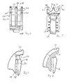
- Fig. 4 shows the cable guide means 24 which has along its arcuate cable guide surface 26 has two grooves 38 and 40.
- the grooves 38 and 40 have a curved arched base.
- the groove walls each have projections 42 which form an undercut.
- the groove partition wall 36 has laterally projections 42 which secure the recorded in the grooves 38 and 40 cables.
- the depth of the grooves 38 and 40 is dimensioned so that the male cable is immersed by more than half in the groove and is held in clamping manner over the projections 42 of the groove walls and the groove partition wall in the groove.
- Fig. 5 shows a view from the front of the inlet region of the grooves 38 and 40.
- the radius of curvature preferably corresponds to the cable radius.
- the tongue 30 of the cable guide device can be seen.
- the tongue 30 defines a slot 28 in which teeth 44 protrude.
- the teeth 44 are disposed on a tongue opposite portion of the cable guide means 24 and extend transversely to the longitudinal direction of the tongue 30.
- the tongue 30 tapers towards its free end and has in Area of the slot bottom a projecting portion 46, through which the clamping pressure of the tongue can be constructed.
- a material recess is provided, which is formed as a recess 32 as an abutment for a band-shaped fastening means.
- the tongue 30 has a small width than the cable guide surface with the juxtaposed grooves 38 and 40th
- Fig. 7 It can be seen that the recess 34 is provided in the groove walls and in the Nutrennwand 36 near the entrance region into the grooves 38 and 40. In the section it can be seen that the tongue 30 has a smaller width than the body of the cable guiding device.
- the cable guide device shown can be retrofitted as a component in a truck by being inserted with its slot on the sheet metal wall. This makes a quick and intuitive operation without special knowledge and tools possible.
- a material a plastic or a similar soft material can be used, the material meets the required fire class.
- the grooves 38, 40 are designed for a line with a defined diameter, for example, 35 mm 2 , so that this line is clamped in the cable guide device.
- On a cable tie for additional attachment can be dispensed with cables with this diameter. If cables with a smaller diameter are routed via the cable guide device, the clamping effect is largely eliminated and the cables are held in the grooves exclusively via the cable tie as a band-shaped fastening means.
Landscapes
- Chemical & Material Sciences (AREA)
- Chemical Kinetics & Catalysis (AREA)
- Electrochemistry (AREA)
- General Chemical & Material Sciences (AREA)
- Engineering & Computer Science (AREA)
- Architecture (AREA)
- Civil Engineering (AREA)
- Structural Engineering (AREA)
- Mechanical Engineering (AREA)
- Installation Of Indoor Wiring (AREA)
- Battery Mounting, Suspending (AREA)
- Insertion, Bundling And Securing Of Wires For Electric Apparatuses (AREA)
Description
- Die vorliegende Erfindung betrifft eine Kabelführungseinrichtung zur Verwendung bei der Installation von Kabeln, insbesondere im Batterieraum eines Fahrzeugs, bevorzugt im Batterieraum eines Flurförderzeugs.
- Ein Flurförderzeug, wie beispielsweise Hubwagen, Gabelstapler oder Kommissionierer weisen eine Vielzahl elektrischer Leitungen auf, die einen elektrischen Antrieb mit einer in dem Fahrzeug mitgeführten Batterie verbinden. Darüber hinaus sind die Fahrzeuge mit einer Vielzahl von elektrischen Signalleitungen ausgestattet, über die die elektrischen Systeme des Flurförderzeugs miteinander verbunden sind. Bei der Verlegung dieser Leitungen in Form von einzelnen Kabeln oder Kabelsträngen ist es in der Regel nicht vermeidbar, die Leitungen auch um Kanten und Ecken zu führen. Insbesondere bei den aus einem Batterieraum des Fahrzeugs herausgeführten Kabeln können Beschädigungen an der Kabelisolation auftreten. Der Batterieraum eines Flurförderzeugs weist in der Regel einen Batterietrog auf, über dessen umgebende Wandung das oder die Kabel geführt sind.
- Eine Beschädigung der Kabelisolierung bei einem in einem Flurförderzeug verlegten Kabel oder Kabelbündel kann zu einer erheblichen Beeinträchtigung des Fahrzeugbetriebs und zu arbeitssicherheitstechnischen Problemen führen.
- Aus
DE 2007 018 333 A1 ist eine Kabelführungseinrichtung bekannt geworden, die ein Befestigungselement und ein mit dem Befestigungselement verbundenes Führungselement aufweist. Das Befestigungselement ist dazu eingerichtet, die Kabelführungseinrichtung an einer ersten von zwei Kanten bildenden Fläche zu befestigen. Das Befestigungselement besitzt eine gekrümmt ausgebildete Auflagefläche für ein zu führendes Kabel, wobei die Krümmung der Auflagefläche an einen vorbestimmten Biegeradius eines zu verlegenden Kabels angepasst ist. Eine Befestigung der Kabel auf der Auflagefläche erfolgt über Kabelbinder, die in seitlichen Ausnehmungen der Auflagefläche ihr Widerlager finden. - Der Erfindung liegt die Aufgabe zugrunde, eine Kabelführungseinrichtung mit einfachen Mitteln bereitzustellen, die eine schnelle und leichte Montage erlaubt.
- Die Aufgabe wird durch eine Kabelführungseinrichtung mit den Merkmalen aus Anspruch 1 gelöst. Vorteilhafte Ausgestaltungen sind in den Unteransprüchen und dem Ausführungsbeispiel beschrieben.
- Die erfindungsgemäße Kabelführungseinrichtung ist zur Verwendung bei der Installation von Kabeln im Batterieraum eines Fahrzeugs, insbesondere eines Flurförderzeugs, vorgesehen. Sie besitzt ein Befestigungselement, das einen Schlitz zum Aufstecken der Kabelführungseinrichtung auf eine flache Wand besitzt. Das Befestigungselement besitzt ferner auf seiner von dem Schlitz abgewandten Seite eine sich in einem Bogen erstreckende Kabelführungsfläche. Bei der erfindungsgemäßen Kabelführungseinrichtung ist die Kabelführungsfläche mit mindestens einer Nut zur Aufnahme eines Kabels ausgestattet. Die Nut erstreckt sich dabei in der gebogenen Längsrichtung der Kabelführungsfläche, so dass das Kabel bogenförmig in der Nut angeordnet werden kann. Die erfindungsgemäße Kabelführungseinrichtung ermöglicht somit die Realisierung eines definierten Kabelverlaufes, sowohl in Längs- als auch in Querrichtung des Kabels. In die Kabelführungseinrichtung, die mit ihrem Schlitz auf eine flache Wand aufgesteckt werden kann, wird ein Kontakt des Kabels mit einer scharfen Kante oder der Wand vermieden, so dass eine Beschädigung der Isolierung ausbleibt. Hinzu kommt, dass die erfindungsgemäße Kabeleinführungseinrichtung mit ihrem Schlitz einfach montiert und auch in bestehenden Anwendungen ohne weiteres nachgerüstet werden kann.
- In einer bevorzugten Ausgestaltung weist die Kabelführungseinrichtung mindestens zwei parallel zueinander verlaufende Nuten auf, von denen jede zur Aufnahme eines Kabels ausgebildet ist. Wenn im Zusammenhang mit der Erfindung auf die Aufnahme eines Kabels in der Nut abgestellt wird, so ist hierbei auch stets der Fall erfasst, dass beispielsweise ein Kabelstrang aus Leitungen, beispielsweise Signalleitungen ein aufzunehmendes Kabel bilden. Die zwei parallel zueinander verlaufenden Nuten in der Kabelführungsfläche erlauben es, Kabelpaare, wie sie beispielsweise zu einer Batterie im Fahrzeug geführt werden, parallel zueinander über die Kante zu führen.
- In einer bevorzugten Ausgestaltung ist das Befestigungselement in der Kabelführungsfläche mit Vertiefungen an der Oberkante der Nut ausgestattet. Die Vertiefungen erstrecken sich quer oder schräg zur Längsrichtung der Nut. Ferner ist das Befestigungselement mit einem Gegenlager für ein durch die Vertiefung geführtes bandförmiges Befestigungsmittel ausgestattet. Über das bandförmige Befestigungsmittel können in der Nut angeordnete Kabel dauerhaft in der Nut gesichert werden, wobei das bandförmige Befestigungsmittel, wie beispielsweise ein Kabelbinder, durch die Vertiefungen und das am Befestigungselement ausgebildete Gegenlager läuft. In einer bevorzugten Ausgestaltung ist das Gegenlager beispielsweise als ein Durchgangsloch oder eine Aussparung in dem Befestigungselement ausgebildet, so dass das bandförmige Befestigungsmittel durch das Durchgangsloch hindurchgeführt, die Kabel in der Nut sichert.
- In einer bevorzugten Ausgestaltung der erfindungsgemäßen Kabelführungseinrichtung besitzt der Schlitz elastische, nach innen in den Schlitz vorstehende Zähne.
- Über die Zähne wird das Befestigungselement in seiner aufgesteckten Position auf der Wand gesichert, sowohl gegen ein seitliches Verrutschen als auch gegen ein versehentliches Abnehmen.
- In einer bevorzugten Ausgestaltung ist das Befestigungselement einstückig, bevorzugt als Spritzgussteil, hergestellt. Das so hergestellte einstückige Befestigungselement kann beispielsweise aus einem Kunststoffmaterial hergestellt sein, das elastisch ausgebildet ist und somit einen guten Sitz auf der Wand aufweist und die in der Nut angeordneten Kabeln federnd lagert.
- Bevorzugt weist die Kabelführungsfläche, bezogen auf ihre Längsrichtung, einen Bogen auf, der einen Winkel von mindestens 70° überstreicht. Die Bogenlänge mit einem Winkel von mindestens 70° gestattet es, das Kabel mit einer definierten Führung um mindestens einen Winkel von 70° umzulenken, so dass es beispielsweise aus einem Batterieraum heraus geführt werden kann.
- In einer zweckmäßigen Ausgestaltung ist mindestens eine Nutwand elastisch oder nach innen vorstehend mit einem Hinterschnitt ausgebildet derart, dass ein in der Nut angeordnetes Kabel gedämpft in der Nut gehalten werden kann. Auf diese Weise kann eine erste Fixierung des Kabels in der Kabelführungseinrichtung durch ein Hereindrücken des Kabels in die Nut erfolgen.
- Die erfindungsgemäße Aufgabe wird ebenfalls durch ein System mit einem Batterieraum gelöst, der eine Wand und ein aus dem Batterieraum herausgeführtes Kabel aufweist, wobei die vorstehende Kabelführungseinrichtung auf die Wand des Batterieraums aufgesteckt und das Kabel in der Nut der Kabelführungsfläche angeordnet ist.
- Ein bevorzugtes Ausführungsbeispiel der erfindungsgemäßen Kabelführungseinrichtung wird anhand der nachfolgenden Figuren näher beschrieben. Es zeigen:
- Fig. 1
- eine geschnittene Ansicht von der Seite auf einen Batterieraum mit einer Kabelführungseinrichtung,
- Fig. 2
- eine perspektivische Ansicht von schräg oben auf den Batterieraum gemäß
Fig. 1 , - Fig. 3
- eine Ansicht von oben auf den Batterieraum gemäß
Fig. 1 , - Fig. 4
- eine Ansicht der Kabelführungseinrichtung von oben,
- Fig. 5
- eine Ansicht auf die Kabelführungseinrichtung von vorne,
- Fig. 6
- eine Ansicht von der Seite auf die Kabelführungseinrichtung und
- Fig. 7
- einen Schnitt entlang der Linie VII - VII in
Fig. 4 . -
Fig. 1 zeigt in einer geschnittenen Darstellung einen Batterieraum 10, in dem mehrere Batterieelemente 12, 14 angeordnet sind. Der Batterieraum 10 besitzt eine Seitenwand 16, die aus Metall oder Kunststoff besteht und eine gleichmäßige Dicke besitzt. Nach hinten ist der Batterieraum durch eine Batteriewand 18 begrenzt. Ein Kabel 20 ist über einen an der hinteren Batteriewand 18 befestigten Anschlussadapter 22 mit den Anschlüssen (nicht dargestellt) der Batterie verbunden. Das Kabel 20 wird aus dem Batterieraum 10 im Bereich der Seitenwand 16 ausgeführt. - Auf die Seitenwand 16 aufgesteckt ist eine Kabelführungseinrichtung 24, die ein Befestigungselement mit einer bogenförmig verlaufenden Kabelführungsfläche 26 besitzt. Die Kabelführungsfläche 26 beginnt oberhalb der Seitenwand 16 und erstreckt sich bogenförmig über einen Winkelbereich von ungefähr 90°, so dass sie parallel zur Seitenwand 16 endet. Die Kabelführungsfläche 16 besitzt eine vertiefte Nut, die das Kabel 12 aufnimmt.
- Die Kabelführungseinrichtung 24 besitzt einen Schlitz 28, mit dem sie auf die Seitenwand 16 aufgesetzt ist. Der Schlitz 28 wird auf seiner zum Batterieraum 10 weisenden Seite durch eine Zunge 30 begrenzt, die integral mit der Kabelführungeinrichtung 24 ausgebildet ist. Zwischen der Zunge 30 und der Kabelführungsfläche 26 ist eine Aussparung 32 ausgebildet, die als Gegenlager für ein bandförmiges Befestigungsmittel (nicht dargestellt) dient. Oberhalb der Aussparung 32 ist in der Kabelführungsfläche 26 eine Vertiefung 34 vorgesehen, die ein bandförmiges Befestigungsmittel aufnehmen kann. Ein Kabelbinder (nicht dargestellt) kann beispielsweise in der Aussparung 32 angeordnet und durch die Vertiefung 34 geführt werden, um das Kabel 20 in der Kabelführungsfläche bzw. in der darin ausgebildeten Nut zu sichern. Alternativ oder zusätzlich zu der Aussparung 32 kann auch eine Durchgangsbohrung vorgesehen sein, durch die ein bandförmiges Befestigungsmittel geführt ist. Wie in
Fig. 1 zu erkennen, erfolgt die Sicherung des Kabels 20 zu Beginn der Kabelführungsfläche 26, also dort, wo das Kabel 20 in den Batterieraum 10 und die Nut auf der Kabelführungsfläche eintritt. -
Fig. 2 zeigt in der perspektivischen Ansicht von schräg oben, dass von dem Kabelanschlussadapter 22 zwei Kabel 20 und 21 parallel zu der Kabelführungseinrichtung 24 geführt sind. Die Kabelführungseinrichtung 24 besitzt zwei parallel zueinander verlaufende Nuten zur Aufnahme der Kabel 20 und 21, wobei die Nuten durch eine zentral verlaufende Nutwand 36 voneinander getrennt sind. Die Nutwand 36 besitzt ebenfalls eine Vertiefung 34 zur Aufnahme eines bandförmigen Befestigungsmittels. - Wie in
Fig. 3 zu erkennen, können die Kabel 20 und 21 auch schräg in die Kabelführungseinrichtung 24 geführt werden. Die Kabelführungseinrichtung 24 führt die Kabel 20 und 21 einerseits in einer definierten Biegung um die Kante 17 der Seitenwand 16 herum und stellt andererseits sicher, dass die Kabel nach Verlassen der Kabelführungsfläche sich senkrecht in Richtung des Bogens weiter erstrecken. -
Fig. 4 zeigt die Kabelführungseinrichtung 24, die entlang ihrer bogenförmig verlaufenden Kabelführungsfläche 26 zwei Nuten 38 und 40 besitzt. Die Nuten 38 und 40 besitzen einen bogenförmig gewölbten Grund. Die Nutwände besitzen jeweils Vorsprünge 42, die einen Hinterschnitt bilden. Auch die Nuttrennwand 36 besitzt seitlich jeweils Vorsprünge 42, die die in die Nuten 38 und 40 aufgenommenen Kabel sichern. Die Tiefe der Nuten 38 und 40 ist so dimensioniert, dass das aufzunehmende Kabel um mehr als die Hälfte in die Nut eintaucht und über die Vorsprünge 42 der Nutwände und der Nuttrennwand klemmend in der Nut gehalten ist. -
Fig. 5 zeigt eine Ansicht von vorne auf den Eintrittsbereich der Nuten 38 und 40. Im oberen Bereich der Nuten 38 und 40 ist der gewölbte Grund der Nuten zu erkennen, dessen Krümmungsradius bevorzugt dem Kabelradius entspricht. - In der Ansicht von der Seite gemäß
Fig. 6 ist die Zunge 30 der Kabelführungseinrichtung zu erkennen. Die Zunge 30 begrenzt einen Schlitz 28, in den Zähne 44 vorstehen. Die Zähne 44 sind an einem der Zunge gegenüberliegenden Abschnitt der Kabelführungseinrichtung 24 angeordnet und erstrecken sich quer zur Längsrichtung der Zunge 30. Die Zunge 30 verjüngt sich zu ihrem freien Ende hin und besitzt im Bereich des Schlitzgrundes einen vorstehenden Bereich 46, über den der Klemmdruck der Zunge aufgebaut werden kann. Oberhalb der Zunge 30 ist eine Materialaussparung vorgesehen, die als Aussparung 32 als Gegenlager für ein bandförmiges Befestigungsmittel ausgebildet ist. Wie in der Ansicht ausFig. 6 zu erkennen, besitzt die Zunge 30 eine geringe Breite als die Kabelführungsfläche mit den nebeneinander angeordneten Nuten 38 und 40. - Aus
Fig. 7 ist zu erkennen, dass die Vertiefung 34 in den Nutenwänden und in der Nutrennwand 36 nahe dem Eintrittsbereich in die Nuten 38 und 40 vorgesehen ist. In dem Schnitt ist zu erkennen, dass die Zunge 30 eine geringere Breite als der Körper der Kabelführungseinrichtung besitzt. - Die dargestellte Kabelführungseinrichtung kann als Bauteil nachträglich in ein Flurförderzeug eingebaut werden, indem diese mit ihrem Schlitz auf die Blechwand gesteckt wird. Hierdurch ist eine schnelle und intuitive Bedienung ohne spezielle Kenntnisse und Werkzeuge möglich. Als Werkstoff kann ein Kunststoff oder ein ähnlich weiches Material verwendet werden, wobei der Werkstoff die erforderliche Brandklasse erfüllt. In der dargestellten Ausführungsform sind die Nuten 38, 40 für eine Leitung mit einem definierten Durchmesser ausgelegt, beispielsweise 35 mm2, so dass diese Leitung klemmend in der Kabelführungseinrichtung sitzt. Auf einen Kabelbinder zur zusätzlichen Befestigung kann bei Kabeln mit diesem Durchmesser verzichtet werden. Werden Kabel mit einem geringeren Durchmesser über die Kabelführungseinrichtung geführt, entfällt die klemmende Wirkung weitgehend und die Kabel werden ausschließlich über den Kabelbinder als bandförmiges Befestigungsmittel in den Nuten gehalten.
-
- 10
- Batterieraum
- 12
- Batterieelement
- 14
- Batterieelement
- 16
- Seitenwand
- 17
- Kante
- 18
- Batteriewand
- 20
- Kabel
- 21
- Kabel
- 22
- Anschlussadapter
- 24
- Kabelführungseinrichtung
- 26
- Kabelführungsfläche
- 28
- Schlitz
- 30
- Zunge
- 32
- Aussparung
- 34
- Vertiefung
- 36
- Nutwand
- 38
- Nut
- 40
- Nut
- 42
- Vorsprünge
- 44
- Zähne
- 46
- vorstehender Bereich
Claims (10)
- Kabelführungseinrichtung zur Verwendung bei der Installation von Kabeln im Batterieraum eines Fahrzeugs, insbesondere eines Flurförderzeugs, die ein Befestigungselement aufweist, das einen Schlitz zum Aufstecken der Kabelführungseinrichtung auf eine flache Wand und eine Kabelführungsfläche besitzt, die sich auf der dem Schlitz abgewandten Seite in einem Bogen erstreckt, wobei die Kabelführungsfläche mindestens eine Nut zur Aufnahme eines Kabels aufweist.
- Kabelführungseinrichtung nach Anspruch 1, dadurch gekennzeichnet, dass mindestens zwei parallel verlaufende Nuten (38, 40) vorgesehen sind, von denen jede zur Aufnahme eines Kabels ausgebildet ist.
- Kabelführungseinrichtung nach Anspruch 1 oder 2, dadurch gekennzeichnet, dass das Befestigungselement in der Kabelführungsfläche Vertiefungen (34) an der Oberkante der Nut aufweist, wobei die Vertiefung (34) quer oder schräg zur Längsrichtung der Nut verläuft, und das Befestigungselement ein Gegenlager für ein durch die Vertiefung geführtes bandförmiges Befestigungsmittel aufweist.
- Kabelführungseinrichtung nach Anspruch 3, dadurch gekennzeichnet, dass das Gegenlager als ein Durchgangsloch oder eine Aussparung (32) in dem Befestigungselement ausgebildet ist.
- Kabelführungseinrichtung nach einem der Ansprüche 1 bis 4, dadurch gekennzeichnet, dass der Schlitz elastische und nach innen in den Schlitzraum vorstehende Zähne aufweist.
- Kabelführungseinrichtung nach einem der Ansprüche 1 bis 5, dadurch gekennzeichnet, dass das Befestigungselement einstückig, insbesondere als Spritzgussteil, ausgebildet ist.
- Kabelführungseinrichtung nach einem Ansprüche 1 bis 6, dadurch gekennzeichnet, dass die Kabelführungsfläche, bezogen auf ihre Längsrichtung, einen Bogen aufweist, der einen Winkel von mindestens 70° überstreicht.
- Kabelführungseinrichtung nach einem der Ansprüche 1 bis 7, dadurch gekennzeichnet, dass mindestens eine Nutwand elastisch und/oder nach innen vorstehend mit einem Hinterschnitt ausgebildet ist, so dass ein in der Nut angeordnetes Kabel klemmend gehalten werden kann.
- System mit einem Batterieraum, der eine Wand und ein aus diesem geführtes Kabel aufweist, wobei eine Kabelführungseinrichtung nach einem der Ansprüche 1 bis 8 auf die Wand des Batterieraumes aufgesteckt und das Kabel in der Nut der Kabelführungsfläche angeordnet ist.
- Flurförderzeug mit einem System gemäß Anspruch 9.
Applications Claiming Priority (1)
| Application Number | Priority Date | Filing Date | Title |
|---|---|---|---|
| DE102012020105.2A DE102012020105A1 (de) | 2012-10-12 | 2012-10-12 | Kabelführungseinrichtung zur Verwendung bei der Installation von Kabeln |
Publications (2)
| Publication Number | Publication Date |
|---|---|
| EP2731215A1 true EP2731215A1 (de) | 2014-05-14 |
| EP2731215B1 EP2731215B1 (de) | 2015-12-30 |
Family
ID=49304663
Family Applications (1)
| Application Number | Title | Priority Date | Filing Date |
|---|---|---|---|
| EP13004810.1A Not-in-force EP2731215B1 (de) | 2012-10-12 | 2013-10-07 | Kabelführungseinrichtung zur Verwendung bei der Installation von Kabeln |
Country Status (3)
| Country | Link |
|---|---|
| EP (1) | EP2731215B1 (de) |
| CN (1) | CN103779812B (de) |
| DE (1) | DE102012020105A1 (de) |
Cited By (1)
| Publication number | Priority date | Publication date | Assignee | Title |
|---|---|---|---|---|
| DE102019219182A1 (de) * | 2019-12-09 | 2021-06-10 | Abb Ag | Kabelbefestigungszubehör |
Families Citing this family (1)
| Publication number | Priority date | Publication date | Assignee | Title |
|---|---|---|---|---|
| CN107947050A (zh) * | 2017-12-19 | 2018-04-20 | 无锡优耐特能源科技有限公司 | 一种电缆理线器 |
Citations (7)
| Publication number | Priority date | Publication date | Assignee | Title |
|---|---|---|---|---|
| DE8715557U1 (de) * | 1987-11-24 | 1988-01-21 | Jungheinrich Unternehmensverwaltung Kg, 2000 Hamburg | Führungsvorrichtung für ein Batteriekabel in einem Flurförderzeug |
| US5962814A (en) * | 1997-10-14 | 1999-10-05 | Yazaki Corporation | Wire harness trough with pivoting guide |
| US6522823B1 (en) * | 2000-11-06 | 2003-02-18 | Adc Telecommunications, Inc. | Low profile cable exit trough |
| EP1953889A2 (de) * | 2007-02-01 | 2008-08-06 | Jungheinrich Aktiengesellschaft | Verbindungskabel zwischen einer Batterie und einem Antriebsmotor eines Flurförderzeugs |
| DE102007018333A1 (de) | 2007-04-18 | 2008-10-23 | Airbus Deutschland Gmbh | Kabelführungseinrichtung und Kabelführungsanordnung zur Verlegung von Kabeln um eine Kante |
| CN201207314Y (zh) * | 2008-05-09 | 2009-03-11 | 奇瑞汽车股份有限公司 | 一种汽车线束保护支架 |
| CN201547400U (zh) * | 2009-11-11 | 2010-08-11 | 奇瑞汽车股份有限公司 | 一种固定支架 |
Family Cites Families (5)
| Publication number | Priority date | Publication date | Assignee | Title |
|---|---|---|---|---|
| US5352854A (en) * | 1993-01-07 | 1994-10-04 | Molex Incorporated | Electrical wire strain relief and wire management system |
| JP3211707B2 (ja) * | 1997-03-11 | 2001-09-25 | 住友電装株式会社 | 電気接続箱 |
| DE29821638U1 (de) * | 1998-12-04 | 1999-02-18 | A. Raymond & Cie, Grenoble | Metallklammer zur Befestigung von drehbaren Kabelhaltern aus Kunststoff auf Blechkanten |
| DE102008024342A1 (de) * | 2008-05-20 | 2009-11-26 | Sitech Sitztechnik Gmbh | Vorrichtung zur Aufnahme, Führung und zum Schutz von elektrischen Leitungen, Schläuchen oder dergleichen, insbesondere zur Schlauch- und Kabelführung in Kraftfahrzeugbauteilen |
| KR20120112728A (ko) * | 2010-01-29 | 2012-10-11 | 우베-니토 카세이 가부시키가이샤 | 케이블 가이드 |
-
2012
- 2012-10-12 DE DE102012020105.2A patent/DE102012020105A1/de not_active Withdrawn
-
2013
- 2013-10-07 EP EP13004810.1A patent/EP2731215B1/de not_active Not-in-force
- 2013-10-12 CN CN201310756879.8A patent/CN103779812B/zh not_active Expired - Fee Related
Patent Citations (7)
| Publication number | Priority date | Publication date | Assignee | Title |
|---|---|---|---|---|
| DE8715557U1 (de) * | 1987-11-24 | 1988-01-21 | Jungheinrich Unternehmensverwaltung Kg, 2000 Hamburg | Führungsvorrichtung für ein Batteriekabel in einem Flurförderzeug |
| US5962814A (en) * | 1997-10-14 | 1999-10-05 | Yazaki Corporation | Wire harness trough with pivoting guide |
| US6522823B1 (en) * | 2000-11-06 | 2003-02-18 | Adc Telecommunications, Inc. | Low profile cable exit trough |
| EP1953889A2 (de) * | 2007-02-01 | 2008-08-06 | Jungheinrich Aktiengesellschaft | Verbindungskabel zwischen einer Batterie und einem Antriebsmotor eines Flurförderzeugs |
| DE102007018333A1 (de) | 2007-04-18 | 2008-10-23 | Airbus Deutschland Gmbh | Kabelführungseinrichtung und Kabelführungsanordnung zur Verlegung von Kabeln um eine Kante |
| CN201207314Y (zh) * | 2008-05-09 | 2009-03-11 | 奇瑞汽车股份有限公司 | 一种汽车线束保护支架 |
| CN201547400U (zh) * | 2009-11-11 | 2010-08-11 | 奇瑞汽车股份有限公司 | 一种固定支架 |
Cited By (3)
| Publication number | Priority date | Publication date | Assignee | Title |
|---|---|---|---|---|
| DE102019219182A1 (de) * | 2019-12-09 | 2021-06-10 | Abb Ag | Kabelbefestigungszubehör |
| US12046883B2 (en) | 2019-12-09 | 2024-07-23 | Abb Ag | Cable fixing accessory |
| DE102019219182B4 (de) * | 2019-12-09 | 2025-08-28 | Abb Ag | Kabelbefestigungszubehör |
Also Published As
| Publication number | Publication date |
|---|---|
| EP2731215B1 (de) | 2015-12-30 |
| DE102012020105A1 (de) | 2014-04-17 |
| CN103779812B (zh) | 2018-01-09 |
| CN103779812A (zh) | 2014-05-07 |
Similar Documents
| Publication | Publication Date | Title |
|---|---|---|
| DE202014011215U1 (de) | Halterahmen für einen Steckverbinder | |
| DE102009016030A1 (de) | Pannenhilfsklemmenanordnung | |
| EP2989685B1 (de) | Direktsteck-druckfederklemme | |
| DE202011005477U1 (de) | Zugentlastungsgehäuse für elektrische Bauteile | |
| DE102009030798A1 (de) | Schutzvorrichtung für flexible Elemente | |
| EP2573883A2 (de) | Abschlusskappe für Stromführungsprofile eines Stromverteileranordnung | |
| EP2731215B1 (de) | Kabelführungseinrichtung zur Verwendung bei der Installation von Kabeln | |
| EP2012390B1 (de) | Erdungsklammer zum Potentialausgleich von Leitungsführungskanälen | |
| EP3374234A1 (de) | Befestigungssystem | |
| DE102007007514B4 (de) | Halteeinrichtung für eine Fahrzeugbatterie | |
| DE102016124609A1 (de) | Verteilerkasten zum Einbau in eine Wandöffnung | |
| DE202010015367U1 (de) | Kabel- Halter oder Fixierelement | |
| EP2783439B1 (de) | Haltesystem mit haltevorrichtung zur aufnahme von leitern, anlage | |
| DE102015113512B3 (de) | Klemmanordnung und Federkraftklemme | |
| DE10232256B4 (de) | Klemmfedervorichtung für eine Federkraftklemme | |
| DE202012010205U1 (de) | Gitterrinne | |
| DE9112605U1 (de) | Kontaktvorrichtung für batteriegespeiste, elektrische Geräte | |
| DE102019121165A1 (de) | System zur Realisierung einer Leuchte mit elektrischem Abgriff mit Leiterhalter | |
| EP3139714B1 (de) | Gehäuse für eine elektronische baugruppe | |
| EP2639910B1 (de) | Geräteeinbaudose für Geräteeinbaukanäle sowie diese umfassender Geräteeinbaukanal | |
| DE102005028063B3 (de) | Klemmfeder für eine Federkraftklemme mit ebener Grundplatte | |
| DE102016103516B4 (de) | Profilleiste | |
| EP3772778B1 (de) | Trägersystem zur befestigung eines länglichen gegenstands sowie spangenaufsatz | |
| WO2012079857A1 (de) | Wischblattvorrichtung | |
| DE102019123949B4 (de) | Elektrische Anschlussklemme mit Klemmfeder |
Legal Events
| Date | Code | Title | Description |
|---|---|---|---|
| PUAI | Public reference made under article 153(3) epc to a published international application that has entered the european phase |
Free format text: ORIGINAL CODE: 0009012 |
|
| 17P | Request for examination filed |
Effective date: 20131007 |
|
| AK | Designated contracting states |
Kind code of ref document: A1 Designated state(s): AL AT BE BG CH CY CZ DE DK EE ES FI FR GB GR HR HU IE IS IT LI LT LU LV MC MK MT NL NO PL PT RO RS SE SI SK SM TR |
|
| AX | Request for extension of the european patent |
Extension state: BA ME |
|
| R17P | Request for examination filed (corrected) |
Effective date: 20141111 |
|
| RBV | Designated contracting states (corrected) |
Designated state(s): AL AT BE BG CH CY CZ DE DK EE ES FI FR GB GR HR HU IE IS IT LI LT LU LV MC MK MT NL NO PL PT RO RS SE SI SK SM TR |
|
| GRAP | Despatch of communication of intention to grant a patent |
Free format text: ORIGINAL CODE: EPIDOSNIGR1 |
|
| INTG | Intention to grant announced |
Effective date: 20150414 |
|
| GRAP | Despatch of communication of intention to grant a patent |
Free format text: ORIGINAL CODE: EPIDOSNIGR1 |
|
| INTG | Intention to grant announced |
Effective date: 20150724 |
|
| GRAS | Grant fee paid |
Free format text: ORIGINAL CODE: EPIDOSNIGR3 |
|
| GRAA | (expected) grant |
Free format text: ORIGINAL CODE: 0009210 |
|
| AK | Designated contracting states |
Kind code of ref document: B1 Designated state(s): AL AT BE BG CH CY CZ DE DK EE ES FI FR GB GR HR HU IE IS IT LI LT LU LV MC MK MT NL NO PL PT RO RS SE SI SK SM TR |
|
| REG | Reference to a national code |
Ref country code: GB Ref legal event code: FG4D Free format text: NOT ENGLISH |
|
| REG | Reference to a national code |
Ref country code: CH Ref legal event code: EP |
|
| REG | Reference to a national code |
Ref country code: AT Ref legal event code: REF Ref document number: 767861 Country of ref document: AT Kind code of ref document: T Effective date: 20160115 |
|
| REG | Reference to a national code |
Ref country code: IE Ref legal event code: FG4D Free format text: LANGUAGE OF EP DOCUMENT: GERMAN |
|
| REG | Reference to a national code |
Ref country code: DE Ref legal event code: R096 Ref document number: 502013001669 Country of ref document: DE |
|
| REG | Reference to a national code |
Ref country code: SE Ref legal event code: TRGR |
|
| REG | Reference to a national code |
Ref country code: LT Ref legal event code: MG4D |
|
| PG25 | Lapsed in a contracting state [announced via postgrant information from national office to epo] |
Ref country code: HR Free format text: LAPSE BECAUSE OF FAILURE TO SUBMIT A TRANSLATION OF THE DESCRIPTION OR TO PAY THE FEE WITHIN THE PRESCRIBED TIME-LIMIT Effective date: 20151230 Ref country code: LT Free format text: LAPSE BECAUSE OF FAILURE TO SUBMIT A TRANSLATION OF THE DESCRIPTION OR TO PAY THE FEE WITHIN THE PRESCRIBED TIME-LIMIT Effective date: 20151230 Ref country code: NO Free format text: LAPSE BECAUSE OF FAILURE TO SUBMIT A TRANSLATION OF THE DESCRIPTION OR TO PAY THE FEE WITHIN THE PRESCRIBED TIME-LIMIT Effective date: 20160330 |
|
| REG | Reference to a national code |
Ref country code: NL Ref legal event code: MP Effective date: 20151230 |
|
| PG25 | Lapsed in a contracting state [announced via postgrant information from national office to epo] |
Ref country code: RS Free format text: LAPSE BECAUSE OF FAILURE TO SUBMIT A TRANSLATION OF THE DESCRIPTION OR TO PAY THE FEE WITHIN THE PRESCRIBED TIME-LIMIT Effective date: 20151230 Ref country code: GR Free format text: LAPSE BECAUSE OF FAILURE TO SUBMIT A TRANSLATION OF THE DESCRIPTION OR TO PAY THE FEE WITHIN THE PRESCRIBED TIME-LIMIT Effective date: 20160331 Ref country code: LV Free format text: LAPSE BECAUSE OF FAILURE TO SUBMIT A TRANSLATION OF THE DESCRIPTION OR TO PAY THE FEE WITHIN THE PRESCRIBED TIME-LIMIT Effective date: 20151230 Ref country code: FI Free format text: LAPSE BECAUSE OF FAILURE TO SUBMIT A TRANSLATION OF THE DESCRIPTION OR TO PAY THE FEE WITHIN THE PRESCRIBED TIME-LIMIT Effective date: 20151230 |
|
| PG25 | Lapsed in a contracting state [announced via postgrant information from national office to epo] |
Ref country code: NL Free format text: LAPSE BECAUSE OF FAILURE TO SUBMIT A TRANSLATION OF THE DESCRIPTION OR TO PAY THE FEE WITHIN THE PRESCRIBED TIME-LIMIT Effective date: 20151230 |
|
| PG25 | Lapsed in a contracting state [announced via postgrant information from national office to epo] |
Ref country code: CZ Free format text: LAPSE BECAUSE OF FAILURE TO SUBMIT A TRANSLATION OF THE DESCRIPTION OR TO PAY THE FEE WITHIN THE PRESCRIBED TIME-LIMIT Effective date: 20151230 Ref country code: ES Free format text: LAPSE BECAUSE OF FAILURE TO SUBMIT A TRANSLATION OF THE DESCRIPTION OR TO PAY THE FEE WITHIN THE PRESCRIBED TIME-LIMIT Effective date: 20151230 |
|
| PG25 | Lapsed in a contracting state [announced via postgrant information from national office to epo] |
Ref country code: PL Free format text: LAPSE BECAUSE OF FAILURE TO SUBMIT A TRANSLATION OF THE DESCRIPTION OR TO PAY THE FEE WITHIN THE PRESCRIBED TIME-LIMIT Effective date: 20151230 Ref country code: SK Free format text: LAPSE BECAUSE OF FAILURE TO SUBMIT A TRANSLATION OF THE DESCRIPTION OR TO PAY THE FEE WITHIN THE PRESCRIBED TIME-LIMIT Effective date: 20151230 Ref country code: EE Free format text: LAPSE BECAUSE OF FAILURE TO SUBMIT A TRANSLATION OF THE DESCRIPTION OR TO PAY THE FEE WITHIN THE PRESCRIBED TIME-LIMIT Effective date: 20151230 Ref country code: IS Free format text: LAPSE BECAUSE OF FAILURE TO SUBMIT A TRANSLATION OF THE DESCRIPTION OR TO PAY THE FEE WITHIN THE PRESCRIBED TIME-LIMIT Effective date: 20160430 Ref country code: RO Free format text: LAPSE BECAUSE OF FAILURE TO SUBMIT A TRANSLATION OF THE DESCRIPTION OR TO PAY THE FEE WITHIN THE PRESCRIBED TIME-LIMIT Effective date: 20151230 Ref country code: SM Free format text: LAPSE BECAUSE OF FAILURE TO SUBMIT A TRANSLATION OF THE DESCRIPTION OR TO PAY THE FEE WITHIN THE PRESCRIBED TIME-LIMIT Effective date: 20151230 Ref country code: PT Free format text: LAPSE BECAUSE OF FAILURE TO SUBMIT A TRANSLATION OF THE DESCRIPTION OR TO PAY THE FEE WITHIN THE PRESCRIBED TIME-LIMIT Effective date: 20160502 |
|
| REG | Reference to a national code |
Ref country code: DE Ref legal event code: R097 Ref document number: 502013001669 Country of ref document: DE |
|
| REG | Reference to a national code |
Ref country code: FR Ref legal event code: PLFP Year of fee payment: 4 |
|
| PG25 | Lapsed in a contracting state [announced via postgrant information from national office to epo] |
Ref country code: DK Free format text: LAPSE BECAUSE OF FAILURE TO SUBMIT A TRANSLATION OF THE DESCRIPTION OR TO PAY THE FEE WITHIN THE PRESCRIBED TIME-LIMIT Effective date: 20151230 |
|
| PLBE | No opposition filed within time limit |
Free format text: ORIGINAL CODE: 0009261 |
|
| STAA | Information on the status of an ep patent application or granted ep patent |
Free format text: STATUS: NO OPPOSITION FILED WITHIN TIME LIMIT |
|
| 26N | No opposition filed |
Effective date: 20161003 |
|
| PG25 | Lapsed in a contracting state [announced via postgrant information from national office to epo] |
Ref country code: SI Free format text: LAPSE BECAUSE OF FAILURE TO SUBMIT A TRANSLATION OF THE DESCRIPTION OR TO PAY THE FEE WITHIN THE PRESCRIBED TIME-LIMIT Effective date: 20151230 Ref country code: BE Free format text: LAPSE BECAUSE OF NON-PAYMENT OF DUE FEES Effective date: 20161031 |
|
| REG | Reference to a national code |
Ref country code: CH Ref legal event code: PL |
|
| REG | Reference to a national code |
Ref country code: IE Ref legal event code: MM4A |
|
| PG25 | Lapsed in a contracting state [announced via postgrant information from national office to epo] |
Ref country code: LI Free format text: LAPSE BECAUSE OF NON-PAYMENT OF DUE FEES Effective date: 20161031 Ref country code: CH Free format text: LAPSE BECAUSE OF NON-PAYMENT OF DUE FEES Effective date: 20161031 |
|
| PG25 | Lapsed in a contracting state [announced via postgrant information from national office to epo] |
Ref country code: LU Free format text: LAPSE BECAUSE OF NON-PAYMENT OF DUE FEES Effective date: 20161007 |
|
| REG | Reference to a national code |
Ref country code: FR Ref legal event code: PLFP Year of fee payment: 5 |
|
| PG25 | Lapsed in a contracting state [announced via postgrant information from national office to epo] |
Ref country code: IE Free format text: LAPSE BECAUSE OF NON-PAYMENT OF DUE FEES Effective date: 20161007 |
|
| REG | Reference to a national code |
Ref country code: BE Ref legal event code: MM Effective date: 20161031 |
|
| PG25 | Lapsed in a contracting state [announced via postgrant information from national office to epo] |
Ref country code: HU Free format text: LAPSE BECAUSE OF FAILURE TO SUBMIT A TRANSLATION OF THE DESCRIPTION OR TO PAY THE FEE WITHIN THE PRESCRIBED TIME-LIMIT; INVALID AB INITIO Effective date: 20131007 Ref country code: CY Free format text: LAPSE BECAUSE OF FAILURE TO SUBMIT A TRANSLATION OF THE DESCRIPTION OR TO PAY THE FEE WITHIN THE PRESCRIBED TIME-LIMIT Effective date: 20151230 |
|
| PG25 | Lapsed in a contracting state [announced via postgrant information from national office to epo] |
Ref country code: MK Free format text: LAPSE BECAUSE OF FAILURE TO SUBMIT A TRANSLATION OF THE DESCRIPTION OR TO PAY THE FEE WITHIN THE PRESCRIBED TIME-LIMIT Effective date: 20151230 Ref country code: MC Free format text: LAPSE BECAUSE OF FAILURE TO SUBMIT A TRANSLATION OF THE DESCRIPTION OR TO PAY THE FEE WITHIN THE PRESCRIBED TIME-LIMIT Effective date: 20151230 Ref country code: MT Free format text: LAPSE BECAUSE OF FAILURE TO SUBMIT A TRANSLATION OF THE DESCRIPTION OR TO PAY THE FEE WITHIN THE PRESCRIBED TIME-LIMIT Effective date: 20151230 |
|
| PG25 | Lapsed in a contracting state [announced via postgrant information from national office to epo] |
Ref country code: BG Free format text: LAPSE BECAUSE OF FAILURE TO SUBMIT A TRANSLATION OF THE DESCRIPTION OR TO PAY THE FEE WITHIN THE PRESCRIBED TIME-LIMIT Effective date: 20151230 |
|
| REG | Reference to a national code |
Ref country code: FR Ref legal event code: PLFP Year of fee payment: 6 |
|
| PG25 | Lapsed in a contracting state [announced via postgrant information from national office to epo] |
Ref country code: AL Free format text: LAPSE BECAUSE OF FAILURE TO SUBMIT A TRANSLATION OF THE DESCRIPTION OR TO PAY THE FEE WITHIN THE PRESCRIBED TIME-LIMIT Effective date: 20151230 Ref country code: TR Free format text: LAPSE BECAUSE OF FAILURE TO SUBMIT A TRANSLATION OF THE DESCRIPTION OR TO PAY THE FEE WITHIN THE PRESCRIBED TIME-LIMIT Effective date: 20151230 |
|
| REG | Reference to a national code |
Ref country code: AT Ref legal event code: MM01 Ref document number: 767861 Country of ref document: AT Kind code of ref document: T Effective date: 20181007 |
|
| PG25 | Lapsed in a contracting state [announced via postgrant information from national office to epo] |
Ref country code: AT Free format text: LAPSE BECAUSE OF NON-PAYMENT OF DUE FEES Effective date: 20181007 |
|
| PGFP | Annual fee paid to national office [announced via postgrant information from national office to epo] |
Ref country code: GB Payment date: 20231025 Year of fee payment: 11 |
|
| PGFP | Annual fee paid to national office [announced via postgrant information from national office to epo] |
Ref country code: SE Payment date: 20231025 Year of fee payment: 11 Ref country code: IT Payment date: 20231031 Year of fee payment: 11 Ref country code: FR Payment date: 20231023 Year of fee payment: 11 Ref country code: DE Payment date: 20231018 Year of fee payment: 11 |
|
| REG | Reference to a national code |
Ref country code: DE Ref legal event code: R119 Ref document number: 502013001669 Country of ref document: DE |
|
| REG | Reference to a national code |
Ref country code: SE Ref legal event code: EUG |
|
| GBPC | Gb: european patent ceased through non-payment of renewal fee |
Effective date: 20241007 |
|
| PG25 | Lapsed in a contracting state [announced via postgrant information from national office to epo] |
Ref country code: DE Free format text: LAPSE BECAUSE OF NON-PAYMENT OF DUE FEES Effective date: 20250501 |
|
| PG25 | Lapsed in a contracting state [announced via postgrant information from national office to epo] |
Ref country code: GB Free format text: LAPSE BECAUSE OF NON-PAYMENT OF DUE FEES Effective date: 20241007 |
|
| PG25 | Lapsed in a contracting state [announced via postgrant information from national office to epo] |
Ref country code: FR Free format text: LAPSE BECAUSE OF NON-PAYMENT OF DUE FEES Effective date: 20241031 |
|
| PG25 | Lapsed in a contracting state [announced via postgrant information from national office to epo] |
Ref country code: SE Free format text: LAPSE BECAUSE OF NON-PAYMENT OF DUE FEES Effective date: 20241008 Ref country code: IT Free format text: LAPSE BECAUSE OF NON-PAYMENT OF DUE FEES Effective date: 20241007 |