EP2730838A1 - Leuchtmodul für einen Kraftfahzeugscheinwerfer mit mehreren Lichtquellen - Google Patents
Leuchtmodul für einen Kraftfahzeugscheinwerfer mit mehreren Lichtquellen Download PDFInfo
- Publication number
- EP2730838A1 EP2730838A1 EP13192221.3A EP13192221A EP2730838A1 EP 2730838 A1 EP2730838 A1 EP 2730838A1 EP 13192221 A EP13192221 A EP 13192221A EP 2730838 A1 EP2730838 A1 EP 2730838A1
- Authority
- EP
- European Patent Office
- Prior art keywords
- light
- sources
- source
- module according
- lens
- Prior art date
- Legal status (The legal status is an assumption and is not a legal conclusion. Google has not performed a legal analysis and makes no representation as to the accuracy of the status listed.)
- Granted
Links
- 238000009826 distribution Methods 0.000 claims abstract description 7
- 230000003287 optical effect Effects 0.000 claims description 11
- 230000009365 direct transmission Effects 0.000 claims description 2
- 238000005286 illumination Methods 0.000 description 12
- 230000004907 flux Effects 0.000 description 7
- 238000004364 calculation method Methods 0.000 description 3
- 238000005457 optimization Methods 0.000 description 3
- 238000010586 diagram Methods 0.000 description 2
- 230000000694 effects Effects 0.000 description 2
- 239000003607 modifier Substances 0.000 description 2
- 230000007480 spreading Effects 0.000 description 2
- 238000003892 spreading Methods 0.000 description 2
- 230000007704 transition Effects 0.000 description 2
- PXFBZOLANLWPMH-UHFFFAOYSA-N 16-Epiaffinine Natural products C1C(C2=CC=CC=C2N2)=C2C(=O)CC2C(=CC)CN(C)C1C2CO PXFBZOLANLWPMH-UHFFFAOYSA-N 0.000 description 1
- 241001080024 Telles Species 0.000 description 1
- 230000003044 adaptive effect Effects 0.000 description 1
- 230000004075 alteration Effects 0.000 description 1
- 230000003466 anti-cipated effect Effects 0.000 description 1
- 230000008901 benefit Effects 0.000 description 1
- 230000000295 complement effect Effects 0.000 description 1
- 238000004590 computer program Methods 0.000 description 1
- 238000010276 construction Methods 0.000 description 1
- 230000001627 detrimental effect Effects 0.000 description 1
- 238000004519 manufacturing process Methods 0.000 description 1
- 239000003550 marker Substances 0.000 description 1
- 239000011159 matrix material Substances 0.000 description 1
- 238000000034 method Methods 0.000 description 1
- 230000003071 parasitic effect Effects 0.000 description 1
- 230000011664 signaling Effects 0.000 description 1
- 239000007787 solid Substances 0.000 description 1
- 230000009466 transformation Effects 0.000 description 1
Images

Classifications
-
- F—MECHANICAL ENGINEERING; LIGHTING; HEATING; WEAPONS; BLASTING
- F21—LIGHTING
- F21V—FUNCTIONAL FEATURES OR DETAILS OF LIGHTING DEVICES OR SYSTEMS THEREOF; STRUCTURAL COMBINATIONS OF LIGHTING DEVICES WITH OTHER ARTICLES, NOT OTHERWISE PROVIDED FOR
- F21V7/00—Reflectors for light sources
- F21V7/04—Optical design
- F21V7/043—Optical design with cylindrical surface
-
- F—MECHANICAL ENGINEERING; LIGHTING; HEATING; WEAPONS; BLASTING
- F21—LIGHTING
- F21S—NON-PORTABLE LIGHTING DEVICES; SYSTEMS THEREOF; VEHICLE LIGHTING DEVICES SPECIALLY ADAPTED FOR VEHICLE EXTERIORS
- F21S41/00—Illuminating devices specially adapted for vehicle exteriors, e.g. headlamps
- F21S41/10—Illuminating devices specially adapted for vehicle exteriors, e.g. headlamps characterised by the light source
- F21S41/14—Illuminating devices specially adapted for vehicle exteriors, e.g. headlamps characterised by the light source characterised by the type of light source
- F21S41/141—Light emitting diodes [LED]
- F21S41/147—Light emitting diodes [LED] the main emission direction of the LED being angled to the optical axis of the illuminating device
- F21S41/148—Light emitting diodes [LED] the main emission direction of the LED being angled to the optical axis of the illuminating device the main emission direction of the LED being perpendicular to the optical axis
-
- F—MECHANICAL ENGINEERING; LIGHTING; HEATING; WEAPONS; BLASTING
- F21—LIGHTING
- F21S—NON-PORTABLE LIGHTING DEVICES; SYSTEMS THEREOF; VEHICLE LIGHTING DEVICES SPECIALLY ADAPTED FOR VEHICLE EXTERIORS
- F21S41/00—Illuminating devices specially adapted for vehicle exteriors, e.g. headlamps
- F21S41/10—Illuminating devices specially adapted for vehicle exteriors, e.g. headlamps characterised by the light source
- F21S41/14—Illuminating devices specially adapted for vehicle exteriors, e.g. headlamps characterised by the light source characterised by the type of light source
- F21S41/141—Light emitting diodes [LED]
- F21S41/151—Light emitting diodes [LED] arranged in one or more lines
-
- F—MECHANICAL ENGINEERING; LIGHTING; HEATING; WEAPONS; BLASTING
- F21—LIGHTING
- F21S—NON-PORTABLE LIGHTING DEVICES; SYSTEMS THEREOF; VEHICLE LIGHTING DEVICES SPECIALLY ADAPTED FOR VEHICLE EXTERIORS
- F21S41/00—Illuminating devices specially adapted for vehicle exteriors, e.g. headlamps
- F21S41/10—Illuminating devices specially adapted for vehicle exteriors, e.g. headlamps characterised by the light source
- F21S41/14—Illuminating devices specially adapted for vehicle exteriors, e.g. headlamps characterised by the light source characterised by the type of light source
- F21S41/141—Light emitting diodes [LED]
- F21S41/155—Surface emitters, e.g. organic light emitting diodes [OLED]
-
- F—MECHANICAL ENGINEERING; LIGHTING; HEATING; WEAPONS; BLASTING
- F21—LIGHTING
- F21S—NON-PORTABLE LIGHTING DEVICES; SYSTEMS THEREOF; VEHICLE LIGHTING DEVICES SPECIALLY ADAPTED FOR VEHICLE EXTERIORS
- F21S41/00—Illuminating devices specially adapted for vehicle exteriors, e.g. headlamps
- F21S41/20—Illuminating devices specially adapted for vehicle exteriors, e.g. headlamps characterised by refractors, transparent cover plates, light guides or filters
- F21S41/25—Projection lenses
- F21S41/275—Lens surfaces, e.g. coatings or surface structures
-
- F—MECHANICAL ENGINEERING; LIGHTING; HEATING; WEAPONS; BLASTING
- F21—LIGHTING
- F21S—NON-PORTABLE LIGHTING DEVICES; SYSTEMS THEREOF; VEHICLE LIGHTING DEVICES SPECIALLY ADAPTED FOR VEHICLE EXTERIORS
- F21S41/00—Illuminating devices specially adapted for vehicle exteriors, e.g. headlamps
- F21S41/30—Illuminating devices specially adapted for vehicle exteriors, e.g. headlamps characterised by reflectors
- F21S41/32—Optical layout thereof
- F21S41/323—Optical layout thereof the reflector having two perpendicular cross sections having regular geometrical curves of a distinct nature
-
- F—MECHANICAL ENGINEERING; LIGHTING; HEATING; WEAPONS; BLASTING
- F21—LIGHTING
- F21S—NON-PORTABLE LIGHTING DEVICES; SYSTEMS THEREOF; VEHICLE LIGHTING DEVICES SPECIALLY ADAPTED FOR VEHICLE EXTERIORS
- F21S41/00—Illuminating devices specially adapted for vehicle exteriors, e.g. headlamps
- F21S41/60—Illuminating devices specially adapted for vehicle exteriors, e.g. headlamps characterised by a variable light distribution
- F21S41/65—Illuminating devices specially adapted for vehicle exteriors, e.g. headlamps characterised by a variable light distribution by acting on light sources
- F21S41/663—Illuminating devices specially adapted for vehicle exteriors, e.g. headlamps characterised by a variable light distribution by acting on light sources by switching light sources
Definitions
- the invention relates to lighting devices such as projectors for motor vehicles.
- the first provides illumination the entire width of the road in front of the vehicle.
- the second provides illumination of the lane in which the vehicle is located and a reduced illumination of the lane located next to it and in which vehicles are likely to come in the opposite direction. In this way, the occupants of the latter are not dazzled.
- the dipped beam function in its most usual form does not illuminate far enough the side of the road beyond this adjacent lane. This is a source of danger. For example, if a pedestrian on the roadside is about to cross the road, it will not be visible early enough by the driver.
- an adaptive fire function has been proposed which makes it possible to illuminate at a great distance and selectively certain parts of the scene in front of the vehicle and in particular the aisle located beyond the adjacent lane.
- an observation device analyzes the scene and selects the areas to be illuminated.
- a projector for implementing this operation is presented in the document EP-2 278 217 . It comprises several contiguous modules intended to form the respective bands. Each module comprises a light source, a reflector and a lens for making one of the strips.
- the reflector has a shape such that it spreads the light of the source in the vertical direction and the lower part of the strip is brighter than its upper part.
- An object of the invention is to overcome this drawback and therefore reduce the volume device for selectively illuminating different areas of the scene visible in front of the vehicle.
- the sources are associated with the same reflector and the same lens.
- the volume of the device is therefore considerably reduced.
- the light source is defined here as the light-emitting surface of a member such as an LED.
- the lens is arranged so that the image formed by the lens of an object placed at one of its homes has a sharp outline throughout its length.
- a net outline is defined as follows:
- I (h, v) be an intensity as a function of two angles h and v (for example equal to log (illumination on a screen at 25 m).
- the contrast is then equal to ⁇ grad (I) ⁇ .
- the outline is said net if at each point the contrast is greater than a predetermined threshold (for example 0.13 according to the European standard).
- the reflector has, in a plane perpendicular to the generatrices of the cylinder, a section shaped to increase a dimension of an image of each source by the reflector and so that a mean value of a luminous flux in an upper half of the image of each source projected by the lens is less than an average value flow in a lower half of the image.
- the light power supplied is greater in the lower part of the spots than in the upper part.
- the reflector has a curved section having a point of inflection, preferably single.
- Such a shape promotes obtaining a good distribution of light in each of the spots in the vertical direction.
- the lens is arranged such that a sharpness of an overall image of the sources provided by the lens is maximum at at least two predetermined points of that image compared with other areas of the image.
- the device thus produces a comfortable lighting for the driver of the vehicle and allows him to apprehend as best as possible the scene in front of the vehicle.
- the points are located on the edges of the images of two sources, these images being immediately adjacent to an image of the same source, these edges being located on the image side of the latter.
- the dots are located on edges of the images of two sources, these images being immediately adjacent to each other, the edge of each image being located on a side opposite the other image .
- Each of these two embodiments represents a good compromise for optimizing the lens and obtaining satisfactory illumination.
- a face of the lens has corrugations.
- This feature makes it possible to slightly blur the top horizontal edge of the stains to avoid having a cut too bright light intensity between the stain and the environment, usually night, which improves the comfort and enjoyment of the driver.
- the face of the lens having the corrugations is an exit face of the source light.
- each source has a square shape in a plane perpendicular to a main direction of emission of light by the source.
- Such sources especially when they consist of light-emitting diodes, have a lower cost than rectangular sources, which makes their use advantageous.
- the module according to the invention makes it possible to obtain a large spreading in the vertical direction from from square sources.
- the module is arranged so that the sources are controllable individually from each other.
- the module comprises a screen forming an obstacle to the direct transmission of light from the sources to the lens.
- a motor vehicle headlight which comprises at least one module according to the invention and preferably comprises several.
- This projector can also constitute a signaling device.
- Another object according to the invention is a motor vehicle comprising at least one module or a lighting device according to the invention.
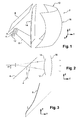
- Module 2 comprises light sources 4, a cover or screen 6, a mirror or reflector 8 and a lens 10.
- FIG. figure 1 An orthogonal reference mark XYZ illustrated in FIG. figure 1 and in which the horizontal axes X and Y are respectively perpendicular and parallel to the direction of travel of the vehicle and the Z axis is vertical.
- the light sources 4 are made in this case in the form of light-emitting diodes. They are arranged to produce upward-directed illumination with their vertical optical axis. They present here a square shape in view in a plane perpendicular to this optical axis. Each source has in plan a surface equal for example to 1 mm 2 . The sources are aligned in a direction parallel to the X axis. The sources are for example carried by a circuit board 12 common to all sources. The number of sources is any. It is greater than or equal to three and the highest possible, each source producing one of the bands forming the lighting.
- the light sources are arranged so that there is a straight line passing through all the sources, in particular by one of the edges of each source.
- the contours of the sources are contained in the same plane.
- Each source has two opposite edges, and the opposite edges of all the sources are parallel to each other. The edges are parallel to the optical axis.
- the screen 6 is arranged to prevent light sources from arriving directly on the lens 10.
- the latter has a rear face 14 and a front face 16 thus referred to by reference to the path of the source light and the direction of travel of the vehicle.
- at least part of the light of each source 4 is reflected by the reflector 8 towards the face 14 and then leaves the lens by the face 16 in the form of parallel rays between them and the Y axis.
- the strips 24 are identical to each other. However one can predict that these bands differ in their width and / or in their length. Similarly, here, the upper and lower horizontal edges of the strips are respectively in coincidence. But this is not obligatory. In addition, a single horizontal row of strips is provided here. But it can be expected that the module produces at least two horizontal rows of strips extending one above the other.
- the face of the reflector 8 exposed to the light of the sources has a cylindrical shape, the generatrices of the cylinder being parallel to the axis X. It has a section in a plane parallel to the axes Y and Z, shown in FIG. figure 3 , on which rely the generators.
- the lens 10 receives light from all sources 4, it is optically optimized so that the bands 24 forming the source images have the sharpest vertical edges possible. We will see later how this optimization is carried out.
- the shape of the reflector 8 is distinct from a line segment and a conic.
- the first is to spread vertically in the vertical direction of the image of each source 4 so that the reflector produces a rectangular image 24 of a square source.
- the second function is to distribute the light power from the source so as to provide more light power in the lower part of the band 24 at the top. More specifically, it is sought to ensure that the light power in the band per unit area is even lower than is located at a great distance from the lower edge of the strip.
- ⁇ are reduced between 0 and 1 by an affine transformation, from the weakest to the strongest.
- the virtual images created at any point of the reflector are of the same size and E r is the emittance of the virtual image of the point (0, y r , z r ).
- the normal orientation of the reflector is calculated to produce the desired offset. Once this orientation has been determined for all the points of the reflector, the position of each point is determined knowing that we start from the lower edge of the reflector which is common to the plane reflector oriented at 45 °. We can build the reflector step by step. This orientation calculation and this construction can be done without difficulty by a computer program.
- an average value of a luminous flux in an upper half of the image 24 of each source projected by the lens is less than an average value of the flux in a lower half of the image.
- the lens 10 is optimized in its two diopters to minimize annoying aberrations.
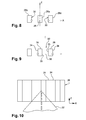
- Figures 8 and 9 two modes of implementation of this optimization. These figures show the images 26 of the sources as reflected by the reflector. These are aligned rectangular strips whose largest dimension is measured in the vertical direction. The tapes are not joined.
- the optical axis 28 of the lens which is parallel to the Y axis, passes through the vertical plane of symmetry of the image 26a from the source located in the center of the alignment.
- the images 26b and 26c of the two adjacent sources are closest to the central image 26a.
- the lens is optimized so that the following two edges benefit from the maximum sharpness: the vertical edge 30 of the image 26c which is the closest to the image 26a and the vertical edge 30 of the image 26b which is the closest from picture 26a.
- the lens is optimized so as to favor the sharpness of the vertical edges closest to the optical axis of the images of the lateral images 26b and 26c.
- the images of the edges of the central image 26a are somewhat fuzzy as are the external lateral edges of the images of the images 26b and 26c. We can then obtain three reasonably sharp bands but having a sharpness lower than the case of the figure 9 explained below.
- the present mode applies when it is desired to have a strong overlap of the beams of the left and right headlights of the vehicle when they are designed in accordance with the invention.
- the optical axis 28 of the lens passes through the vertical plane of symmetry of the interval 32 located in the center of the alignment, between two of the images 26. It is therefore two images adjacent to each other .
- the lens is optimized so that the edge 35 of each of these two images 26 which is furthest from the gap has the maximum sharpness. This case is applicable when the beam of the module extends weakly towards the interior of the vehicle. In this case, the images of the edges of the images closest to the optical axis are a little fuzzy. This case makes it possible to obtain two very sharp bands and applies when it is desired to have a low overlap of the beams of the left and right headlights of the vehicle when they are designed in accordance with the invention.
- the module according to the invention makes it possible in particular to obtain strips whose vertical edges are suitably sharp.
- the module according to the invention makes it possible to produce a beam that does not have black stripes on the image 20 between the strips 24. This avoids a combing effect that is detrimental to the appearance.
- the exit face 16 of the lens has corrugations having a depth of a few microns. These corrugations have the effect of slightly blurring the small upper and lower sides of each strip so that the light transition between the strip and its environment at its vertical ends is carried out as gently as possible.
- the sources are addressable so as to make it possible to control, by means of appropriate control means of the module, the production of each band of light individually from each other.
- the greatest total length measured along the Y axis between the lens and the reflector may be about 40 mm.
- This module can also provide the function of high beams and / or low beam, possibly alone or in addition to one or more other devices.
- a projector comprising such a module may also be equipped with one or more traffic lights.
Landscapes
- Engineering & Computer Science (AREA)
- General Engineering & Computer Science (AREA)
- Physics & Mathematics (AREA)
- Microelectronics & Electronic Packaging (AREA)
- Optics & Photonics (AREA)
- Geometry (AREA)
- Non-Portable Lighting Devices Or Systems Thereof (AREA)
- Lighting Device Outwards From Vehicle And Optical Signal (AREA)
Applications Claiming Priority (1)
| Application Number | Priority Date | Filing Date | Title |
|---|---|---|---|
| FR1260695A FR2998036B1 (fr) | 2012-11-12 | 2012-11-12 | Module d'eclairage pour projecteur de vehicule automobile comprenant plusieurs sources lumineuses |
Publications (2)
| Publication Number | Publication Date |
|---|---|
| EP2730838A1 true EP2730838A1 (de) | 2014-05-14 |
| EP2730838B1 EP2730838B1 (de) | 2020-04-22 |
Family
ID=48237021
Family Applications (1)
| Application Number | Title | Priority Date | Filing Date |
|---|---|---|---|
| EP13192221.3A Active EP2730838B1 (de) | 2012-11-12 | 2013-11-08 | Leuchtmodul für einen Kraftfahzeugscheinwerfer mit mehreren Lichtquellen |
Country Status (3)
| Country | Link |
|---|---|
| EP (1) | EP2730838B1 (de) |
| JP (1) | JP6309246B2 (de) |
| FR (1) | FR2998036B1 (de) |
Cited By (2)
| Publication number | Priority date | Publication date | Assignee | Title |
|---|---|---|---|---|
| EP3141804A1 (de) | 2015-09-14 | 2017-03-15 | Valeo Vision | Beleuchtungsmodul für kraftfahrzeugscheinwerfer, und entsprechender scheinwerfer |
| FR3130011A1 (fr) * | 2021-12-07 | 2023-06-09 | Valeo Vision | Dispositif lumineux d’un véhicule automobile |
Families Citing this family (1)
| Publication number | Priority date | Publication date | Assignee | Title |
|---|---|---|---|---|
| CN106537029B (zh) * | 2014-09-30 | 2019-05-14 | 麦克赛尔株式会社 | 车辆用灯具 |
Citations (8)
| Publication number | Priority date | Publication date | Assignee | Title |
|---|---|---|---|---|
| FR2535014A1 (fr) * | 1982-10-26 | 1984-04-27 | Bui Hai Nhu | Dispositif d'eclairage aerodynamique a couverture azimutale elargie |
| EP0997343A2 (de) * | 1998-10-27 | 2000-05-03 | Stanley Electric Co., Ltd. | Fahrzeugscheinwerfer |
| US20070230204A1 (en) * | 2006-03-29 | 2007-10-04 | Koito Manufacturing Co., Ltd. | Lamp unit of vehicle headlamp |
| WO2009130655A2 (en) * | 2008-04-25 | 2009-10-29 | Philips Intellectual Property & Standards Gmbh | Lamp assembly |
| EP2237080A1 (de) * | 2009-03-31 | 2010-10-06 | Valeo Vision | Linse für ein Beleuchtungsmodul für ein automobiles Fahrzeug |
| EP2278217A1 (de) * | 2009-07-21 | 2011-01-26 | Valeo Vision | Beleuchtungsmodul für Fahrzeugscheinwerfer, und mit wenigstens einem solchen Modul ausgerüsteter Scheinwerfer |
| WO2011086969A1 (ja) * | 2010-01-12 | 2011-07-21 | 株式会社小糸製作所 | 車両用ヘッドランプ |
| EP2500628A2 (de) * | 2011-03-14 | 2012-09-19 | Stanley Electric Co., Ltd. | KFZ-Scheinwerfer |
Family Cites Families (5)
| Publication number | Priority date | Publication date | Assignee | Title |
|---|---|---|---|---|
| JP4615417B2 (ja) * | 2005-10-13 | 2011-01-19 | 株式会社小糸製作所 | 車両用前照灯の灯具ユニット |
| JP5069985B2 (ja) * | 2007-09-13 | 2012-11-07 | 株式会社小糸製作所 | 車両用前照灯の灯具ユニットおよび車両用前照灯 |
| US20100246203A1 (en) * | 2009-03-27 | 2010-09-30 | North American Lighting, Inc. | System and method for exterior lighting of vehicles |
| JP2011238497A (ja) * | 2010-05-12 | 2011-11-24 | Stanley Electric Co Ltd | Led光源ユニットを用いた灯具 |
| JP5640306B2 (ja) * | 2011-03-14 | 2014-12-17 | スタンレー電気株式会社 | 灯具ユニット |
-
2012
- 2012-11-12 FR FR1260695A patent/FR2998036B1/fr active Active
-
2013
- 2013-11-08 EP EP13192221.3A patent/EP2730838B1/de active Active
- 2013-11-11 JP JP2013232705A patent/JP6309246B2/ja active Active
Patent Citations (8)
| Publication number | Priority date | Publication date | Assignee | Title |
|---|---|---|---|---|
| FR2535014A1 (fr) * | 1982-10-26 | 1984-04-27 | Bui Hai Nhu | Dispositif d'eclairage aerodynamique a couverture azimutale elargie |
| EP0997343A2 (de) * | 1998-10-27 | 2000-05-03 | Stanley Electric Co., Ltd. | Fahrzeugscheinwerfer |
| US20070230204A1 (en) * | 2006-03-29 | 2007-10-04 | Koito Manufacturing Co., Ltd. | Lamp unit of vehicle headlamp |
| WO2009130655A2 (en) * | 2008-04-25 | 2009-10-29 | Philips Intellectual Property & Standards Gmbh | Lamp assembly |
| EP2237080A1 (de) * | 2009-03-31 | 2010-10-06 | Valeo Vision | Linse für ein Beleuchtungsmodul für ein automobiles Fahrzeug |
| EP2278217A1 (de) * | 2009-07-21 | 2011-01-26 | Valeo Vision | Beleuchtungsmodul für Fahrzeugscheinwerfer, und mit wenigstens einem solchen Modul ausgerüsteter Scheinwerfer |
| WO2011086969A1 (ja) * | 2010-01-12 | 2011-07-21 | 株式会社小糸製作所 | 車両用ヘッドランプ |
| EP2500628A2 (de) * | 2011-03-14 | 2012-09-19 | Stanley Electric Co., Ltd. | KFZ-Scheinwerfer |
Cited By (3)
| Publication number | Priority date | Publication date | Assignee | Title |
|---|---|---|---|---|
| EP3141804A1 (de) | 2015-09-14 | 2017-03-15 | Valeo Vision | Beleuchtungsmodul für kraftfahrzeugscheinwerfer, und entsprechender scheinwerfer |
| FR3130011A1 (fr) * | 2021-12-07 | 2023-06-09 | Valeo Vision | Dispositif lumineux d’un véhicule automobile |
| WO2023104833A1 (fr) * | 2021-12-07 | 2023-06-15 | Valeo Vision | Dispositif lumineux d'un véhicule automobile |
Also Published As
| Publication number | Publication date |
|---|---|
| EP2730838B1 (de) | 2020-04-22 |
| FR2998036A1 (fr) | 2014-05-16 |
| FR2998036B1 (fr) | 2015-05-01 |
| JP6309246B2 (ja) | 2018-04-11 |
| JP2014096368A (ja) | 2014-05-22 |
Similar Documents
| Publication | Publication Date | Title |
|---|---|---|
| EP2690352B1 (de) | Adaptives Beleuchtungssystem für Kraftfahrzeug | |
| EP3073185B1 (de) | Beleuchtungsmodul für scheinwerfer von kraftfahrzeugen, sowie scheinwerfer, der mit mindestens einem solchen modul ausgestattet ist | |
| EP1610057B1 (de) | Beleuchtungseinheit für Kfz-Scheinwerfer und Scheinwefer mit einer derartigen Einheit | |
| EP3301347B1 (de) | Beleuchtungsvorrichtung für kraftfahrzeug, die einen lichtwellenleiter umfasst | |
| EP2237080A1 (de) | Linse für ein Beleuchtungsmodul für ein automobiles Fahrzeug | |
| EP3470728A1 (de) | Leuchtmodul für kraftfahrzeug | |
| EP2813395A1 (de) | Kraftfahrzeug-Scheinwerfer, der eine Laser-Lichtquelle umfasst und Verfahren zur Erzeugung eines Lichtbündel | |
| EP3611425B1 (de) | Leuchtmodul eines kraftfahrzeugs, das in der lage ist, einen lichtstrahl mit mindestens einer reihe von leuchteinheiten zu erzeugen | |
| EP2479064B1 (de) | Verfahren und Vorrichtung zur Kontrolle eines Lichtbündels, das von einem Fahrzeug, insbesondere einem Auto, ausgesandt wird | |
| EP2415636A2 (de) | Beleuchtungssystem für Kraftfahrzeug | |
| EP2060442A2 (de) | Beleuchtungsvorrichtung für Kraftfahrzeug | |
| EP1870633A1 (de) | Scheinwerfermodul mit Elektrolumineszenzdiode | |
| EP2597360A1 (de) | Lichtemittierende Einrichtung für Kraftfahrzeugscheinwerfer | |
| EP2730838B1 (de) | Leuchtmodul für einen Kraftfahzeugscheinwerfer mit mehreren Lichtquellen | |
| EP3511608B1 (de) | Optisches modul für ein kraftfahrzeug | |
| EP2472176B1 (de) | Beleuchtungs- und/oder signalisierungsvorrichtung, insbesondere für kraftfahrzeug | |
| EP2944514A1 (de) | Beleuchtungsmodul für kraftfahrzeugscheinwerfer, das mehrere lichtquellen umfasst | |
| FR3019266A1 (fr) | Systeme d'eclairage pour vehicule avec reglage automatise | |
| FR3035973A1 (fr) | Dispositif de projection d'indications lumineuses | |
| WO2024094536A1 (fr) | Dispositif d'éclairage | |
| WO2024094529A1 (fr) | Dispositif d'éclairage | |
| WO2023030808A1 (fr) | Module lumineux pour vehicule automobile | |
| FR3056695A1 (fr) | Dispositif d'eclairage pour vehicule automobile comportant un guide de lumiere | |
| EP3081849B1 (de) | Beleuchtungssystem für kkz-scheinwerfer, das ein beleuchtungsmodul mit optimiertem platzbedarf umfasst | |
| FR2821148A1 (fr) | Procede de determination de la surface reflechissante d'un reflecteur, et lampe de vehicule |
Legal Events
| Date | Code | Title | Description |
|---|---|---|---|
| PUAI | Public reference made under article 153(3) epc to a published international application that has entered the european phase |
Free format text: ORIGINAL CODE: 0009012 |
|
| 17P | Request for examination filed |
Effective date: 20131108 |
|
| AK | Designated contracting states |
Kind code of ref document: A1 Designated state(s): AL AT BE BG CH CY CZ DE DK EE ES FI FR GB GR HR HU IE IS IT LI LT LU LV MC MK MT NL NO PL PT RO RS SE SI SK SM TR |
|
| AX | Request for extension of the european patent |
Extension state: BA ME |
|
| R17P | Request for examination filed (corrected) |
Effective date: 20141010 |
|
| RBV | Designated contracting states (corrected) |
Designated state(s): AL AT BE BG CH CY CZ DE DK EE ES FI FR GB GR HR HU IE IS IT LI LT LU LV MC MK MT NL NO PL PT RO RS SE SI SK SM TR |
|
| STAA | Information on the status of an ep patent application or granted ep patent |
Free format text: STATUS: EXAMINATION IS IN PROGRESS |
|
| 17Q | First examination report despatched |
Effective date: 20180924 |
|
| REG | Reference to a national code |
Ref country code: DE Ref legal event code: R079 Ref document number: 602013068122 Country of ref document: DE Free format text: PREVIOUS MAIN CLASS: F21S0008100000 Ipc: F21S0041147000 |
|
| RIC1 | Information provided on ipc code assigned before grant |
Ipc: F21S 41/155 20180101ALI20191011BHEP Ipc: F21S 41/663 20180101ALI20191011BHEP Ipc: F21S 41/32 20180101ALI20191011BHEP Ipc: F21S 41/147 20180101AFI20191011BHEP Ipc: F21V 7/04 20060101ALI20191011BHEP Ipc: F21S 41/275 20180101ALI20191011BHEP |
|
| GRAP | Despatch of communication of intention to grant a patent |
Free format text: ORIGINAL CODE: EPIDOSNIGR1 |
|
| STAA | Information on the status of an ep patent application or granted ep patent |
Free format text: STATUS: GRANT OF PATENT IS INTENDED |
|
| INTG | Intention to grant announced |
Effective date: 20191203 |
|
| GRAS | Grant fee paid |
Free format text: ORIGINAL CODE: EPIDOSNIGR3 |
|
| GRAA | (expected) grant |
Free format text: ORIGINAL CODE: 0009210 |
|
| STAA | Information on the status of an ep patent application or granted ep patent |
Free format text: STATUS: THE PATENT HAS BEEN GRANTED |
|
| AK | Designated contracting states |
Kind code of ref document: B1 Designated state(s): AL AT BE BG CH CY CZ DE DK EE ES FI FR GB GR HR HU IE IS IT LI LT LU LV MC MK MT NL NO PL PT RO RS SE SI SK SM TR |
|
| REG | Reference to a national code |
Ref country code: GB Ref legal event code: FG4D Free format text: NOT ENGLISH |
|
| REG | Reference to a national code |
Ref country code: CH Ref legal event code: EP |
|
| REG | Reference to a national code |
Ref country code: IE Ref legal event code: FG4D Free format text: LANGUAGE OF EP DOCUMENT: FRENCH |
|
| REG | Reference to a national code |
Ref country code: DE Ref legal event code: R096 Ref document number: 602013068122 Country of ref document: DE |
|
| REG | Reference to a national code |
Ref country code: AT Ref legal event code: REF Ref document number: 1260586 Country of ref document: AT Kind code of ref document: T Effective date: 20200515 |
|
| REG | Reference to a national code |
Ref country code: LT Ref legal event code: MG4D |
|
| REG | Reference to a national code |
Ref country code: NL Ref legal event code: MP Effective date: 20200422 |
|
| PG25 | Lapsed in a contracting state [announced via postgrant information from national office to epo] |
Ref country code: IS Free format text: LAPSE BECAUSE OF FAILURE TO SUBMIT A TRANSLATION OF THE DESCRIPTION OR TO PAY THE FEE WITHIN THE PRESCRIBED TIME-LIMIT Effective date: 20200822 Ref country code: NO Free format text: LAPSE BECAUSE OF FAILURE TO SUBMIT A TRANSLATION OF THE DESCRIPTION OR TO PAY THE FEE WITHIN THE PRESCRIBED TIME-LIMIT Effective date: 20200722 Ref country code: FI Free format text: LAPSE BECAUSE OF FAILURE TO SUBMIT A TRANSLATION OF THE DESCRIPTION OR TO PAY THE FEE WITHIN THE PRESCRIBED TIME-LIMIT Effective date: 20200422 Ref country code: NL Free format text: LAPSE BECAUSE OF FAILURE TO SUBMIT A TRANSLATION OF THE DESCRIPTION OR TO PAY THE FEE WITHIN THE PRESCRIBED TIME-LIMIT Effective date: 20200422 Ref country code: SE Free format text: LAPSE BECAUSE OF FAILURE TO SUBMIT A TRANSLATION OF THE DESCRIPTION OR TO PAY THE FEE WITHIN THE PRESCRIBED TIME-LIMIT Effective date: 20200422 Ref country code: PT Free format text: LAPSE BECAUSE OF FAILURE TO SUBMIT A TRANSLATION OF THE DESCRIPTION OR TO PAY THE FEE WITHIN THE PRESCRIBED TIME-LIMIT Effective date: 20200824 Ref country code: GR Free format text: LAPSE BECAUSE OF FAILURE TO SUBMIT A TRANSLATION OF THE DESCRIPTION OR TO PAY THE FEE WITHIN THE PRESCRIBED TIME-LIMIT Effective date: 20200723 Ref country code: LT Free format text: LAPSE BECAUSE OF FAILURE TO SUBMIT A TRANSLATION OF THE DESCRIPTION OR TO PAY THE FEE WITHIN THE PRESCRIBED TIME-LIMIT Effective date: 20200422 |
|
| REG | Reference to a national code |
Ref country code: AT Ref legal event code: MK05 Ref document number: 1260586 Country of ref document: AT Kind code of ref document: T Effective date: 20200422 |
|
| PG25 | Lapsed in a contracting state [announced via postgrant information from national office to epo] |
Ref country code: BG Free format text: LAPSE BECAUSE OF FAILURE TO SUBMIT A TRANSLATION OF THE DESCRIPTION OR TO PAY THE FEE WITHIN THE PRESCRIBED TIME-LIMIT Effective date: 20200722 Ref country code: RS Free format text: LAPSE BECAUSE OF FAILURE TO SUBMIT A TRANSLATION OF THE DESCRIPTION OR TO PAY THE FEE WITHIN THE PRESCRIBED TIME-LIMIT Effective date: 20200422 Ref country code: LV Free format text: LAPSE BECAUSE OF FAILURE TO SUBMIT A TRANSLATION OF THE DESCRIPTION OR TO PAY THE FEE WITHIN THE PRESCRIBED TIME-LIMIT Effective date: 20200422 Ref country code: HR Free format text: LAPSE BECAUSE OF FAILURE TO SUBMIT A TRANSLATION OF THE DESCRIPTION OR TO PAY THE FEE WITHIN THE PRESCRIBED TIME-LIMIT Effective date: 20200422 |
|
| PG25 | Lapsed in a contracting state [announced via postgrant information from national office to epo] |
Ref country code: AL Free format text: LAPSE BECAUSE OF FAILURE TO SUBMIT A TRANSLATION OF THE DESCRIPTION OR TO PAY THE FEE WITHIN THE PRESCRIBED TIME-LIMIT Effective date: 20200422 |
|
| REG | Reference to a national code |
Ref country code: DE Ref legal event code: R097 Ref document number: 602013068122 Country of ref document: DE |
|
| PG25 | Lapsed in a contracting state [announced via postgrant information from national office to epo] |
Ref country code: AT Free format text: LAPSE BECAUSE OF FAILURE TO SUBMIT A TRANSLATION OF THE DESCRIPTION OR TO PAY THE FEE WITHIN THE PRESCRIBED TIME-LIMIT Effective date: 20200422 Ref country code: EE Free format text: LAPSE BECAUSE OF FAILURE TO SUBMIT A TRANSLATION OF THE DESCRIPTION OR TO PAY THE FEE WITHIN THE PRESCRIBED TIME-LIMIT Effective date: 20200422 Ref country code: SM Free format text: LAPSE BECAUSE OF FAILURE TO SUBMIT A TRANSLATION OF THE DESCRIPTION OR TO PAY THE FEE WITHIN THE PRESCRIBED TIME-LIMIT Effective date: 20200422 Ref country code: IT Free format text: LAPSE BECAUSE OF FAILURE TO SUBMIT A TRANSLATION OF THE DESCRIPTION OR TO PAY THE FEE WITHIN THE PRESCRIBED TIME-LIMIT Effective date: 20200422 Ref country code: DK Free format text: LAPSE BECAUSE OF FAILURE TO SUBMIT A TRANSLATION OF THE DESCRIPTION OR TO PAY THE FEE WITHIN THE PRESCRIBED TIME-LIMIT Effective date: 20200422 Ref country code: CZ Free format text: LAPSE BECAUSE OF FAILURE TO SUBMIT A TRANSLATION OF THE DESCRIPTION OR TO PAY THE FEE WITHIN THE PRESCRIBED TIME-LIMIT Effective date: 20200422 Ref country code: RO Free format text: LAPSE BECAUSE OF FAILURE TO SUBMIT A TRANSLATION OF THE DESCRIPTION OR TO PAY THE FEE WITHIN THE PRESCRIBED TIME-LIMIT Effective date: 20200422 Ref country code: ES Free format text: LAPSE BECAUSE OF FAILURE TO SUBMIT A TRANSLATION OF THE DESCRIPTION OR TO PAY THE FEE WITHIN THE PRESCRIBED TIME-LIMIT Effective date: 20200422 |
|
| PG25 | Lapsed in a contracting state [announced via postgrant information from national office to epo] |
Ref country code: PL Free format text: LAPSE BECAUSE OF FAILURE TO SUBMIT A TRANSLATION OF THE DESCRIPTION OR TO PAY THE FEE WITHIN THE PRESCRIBED TIME-LIMIT Effective date: 20200422 Ref country code: SK Free format text: LAPSE BECAUSE OF FAILURE TO SUBMIT A TRANSLATION OF THE DESCRIPTION OR TO PAY THE FEE WITHIN THE PRESCRIBED TIME-LIMIT Effective date: 20200422 |
|
| PLBE | No opposition filed within time limit |
Free format text: ORIGINAL CODE: 0009261 |
|
| STAA | Information on the status of an ep patent application or granted ep patent |
Free format text: STATUS: NO OPPOSITION FILED WITHIN TIME LIMIT |
|
| 26N | No opposition filed |
Effective date: 20210125 |
|
| PG25 | Lapsed in a contracting state [announced via postgrant information from national office to epo] |
Ref country code: SI Free format text: LAPSE BECAUSE OF FAILURE TO SUBMIT A TRANSLATION OF THE DESCRIPTION OR TO PAY THE FEE WITHIN THE PRESCRIBED TIME-LIMIT Effective date: 20200422 |
|
| PG25 | Lapsed in a contracting state [announced via postgrant information from national office to epo] |
Ref country code: MC Free format text: LAPSE BECAUSE OF FAILURE TO SUBMIT A TRANSLATION OF THE DESCRIPTION OR TO PAY THE FEE WITHIN THE PRESCRIBED TIME-LIMIT Effective date: 20200422 |
|
| REG | Reference to a national code |
Ref country code: CH Ref legal event code: PL |
|
| GBPC | Gb: european patent ceased through non-payment of renewal fee |
Effective date: 20201108 |
|
| PG25 | Lapsed in a contracting state [announced via postgrant information from national office to epo] |
Ref country code: LU Free format text: LAPSE BECAUSE OF NON-PAYMENT OF DUE FEES Effective date: 20201108 |
|
| REG | Reference to a national code |
Ref country code: BE Ref legal event code: MM Effective date: 20201130 |
|
| PG25 | Lapsed in a contracting state [announced via postgrant information from national office to epo] |
Ref country code: LI Free format text: LAPSE BECAUSE OF NON-PAYMENT OF DUE FEES Effective date: 20201130 Ref country code: CH Free format text: LAPSE BECAUSE OF NON-PAYMENT OF DUE FEES Effective date: 20201130 |
|
| PG25 | Lapsed in a contracting state [announced via postgrant information from national office to epo] |
Ref country code: IE Free format text: LAPSE BECAUSE OF NON-PAYMENT OF DUE FEES Effective date: 20201108 |
|
| PG25 | Lapsed in a contracting state [announced via postgrant information from national office to epo] |
Ref country code: GB Free format text: LAPSE BECAUSE OF NON-PAYMENT OF DUE FEES Effective date: 20201108 |
|
| PG25 | Lapsed in a contracting state [announced via postgrant information from national office to epo] |
Ref country code: TR Free format text: LAPSE BECAUSE OF FAILURE TO SUBMIT A TRANSLATION OF THE DESCRIPTION OR TO PAY THE FEE WITHIN THE PRESCRIBED TIME-LIMIT Effective date: 20200422 Ref country code: MT Free format text: LAPSE BECAUSE OF FAILURE TO SUBMIT A TRANSLATION OF THE DESCRIPTION OR TO PAY THE FEE WITHIN THE PRESCRIBED TIME-LIMIT Effective date: 20200422 Ref country code: CY Free format text: LAPSE BECAUSE OF FAILURE TO SUBMIT A TRANSLATION OF THE DESCRIPTION OR TO PAY THE FEE WITHIN THE PRESCRIBED TIME-LIMIT Effective date: 20200422 |
|
| PG25 | Lapsed in a contracting state [announced via postgrant information from national office to epo] |
Ref country code: MK Free format text: LAPSE BECAUSE OF FAILURE TO SUBMIT A TRANSLATION OF THE DESCRIPTION OR TO PAY THE FEE WITHIN THE PRESCRIBED TIME-LIMIT Effective date: 20200422 |
|
| PG25 | Lapsed in a contracting state [announced via postgrant information from national office to epo] |
Ref country code: BE Free format text: LAPSE BECAUSE OF NON-PAYMENT OF DUE FEES Effective date: 20201130 |
|
| P01 | Opt-out of the competence of the unified patent court (upc) registered |
Effective date: 20230528 |
|
| PGFP | Annual fee paid to national office [announced via postgrant information from national office to epo] |
Ref country code: FR Payment date: 20231124 Year of fee payment: 11 Ref country code: DE Payment date: 20231107 Year of fee payment: 11 |