EP2729679B1 - Verfahren zur herstellung einer abgasanlage sowie abgasanlage - Google Patents
Verfahren zur herstellung einer abgasanlage sowie abgasanlage Download PDFInfo
- Publication number
- EP2729679B1 EP2729679B1 EP12729361.1A EP12729361A EP2729679B1 EP 2729679 B1 EP2729679 B1 EP 2729679B1 EP 12729361 A EP12729361 A EP 12729361A EP 2729679 B1 EP2729679 B1 EP 2729679B1
- Authority
- EP
- European Patent Office
- Prior art keywords
- pipe sections
- exhaust system
- pipe
- exhaust gas
- gas system
- Prior art date
- Legal status (The legal status is an assumption and is not a legal conclusion. Google has not performed a legal analysis and makes no representation as to the accuracy of the status listed.)
- Active
Links
Images



Classifications
-
- F—MECHANICAL ENGINEERING; LIGHTING; HEATING; WEAPONS; BLASTING
- F16—ENGINEERING ELEMENTS AND UNITS; GENERAL MEASURES FOR PRODUCING AND MAINTAINING EFFECTIVE FUNCTIONING OF MACHINES OR INSTALLATIONS; THERMAL INSULATION IN GENERAL
- F16L—PIPES; JOINTS OR FITTINGS FOR PIPES; SUPPORTS FOR PIPES, CABLES OR PROTECTIVE TUBING; MEANS FOR THERMAL INSULATION IN GENERAL
- F16L13/00—Non-disconnectable pipe joints, e.g. soldered, adhesive, or caulked joints
- F16L13/08—Soldered joints
-
- F—MECHANICAL ENGINEERING; LIGHTING; HEATING; WEAPONS; BLASTING
- F01—MACHINES OR ENGINES IN GENERAL; ENGINE PLANTS IN GENERAL; STEAM ENGINES
- F01N—GAS-FLOW SILENCERS OR EXHAUST APPARATUS FOR MACHINES OR ENGINES IN GENERAL; GAS-FLOW SILENCERS OR EXHAUST APPARATUS FOR INTERNAL-COMBUSTION ENGINES
- F01N13/00—Exhaust or silencing apparatus characterised by constructional features
- F01N13/18—Construction facilitating manufacture, assembly, or disassembly
- F01N13/1805—Fixing exhaust manifolds, exhaust pipes or pipe sections to each other, to engine or to vehicle body
-
- F—MECHANICAL ENGINEERING; LIGHTING; HEATING; WEAPONS; BLASTING
- F01—MACHINES OR ENGINES IN GENERAL; ENGINE PLANTS IN GENERAL; STEAM ENGINES
- F01N—GAS-FLOW SILENCERS OR EXHAUST APPARATUS FOR MACHINES OR ENGINES IN GENERAL; GAS-FLOW SILENCERS OR EXHAUST APPARATUS FOR INTERNAL-COMBUSTION ENGINES
- F01N13/00—Exhaust or silencing apparatus characterised by constructional features
- F01N13/18—Construction facilitating manufacture, assembly, or disassembly
- F01N13/1838—Construction facilitating manufacture, assembly, or disassembly characterised by the type of connection between parts of exhaust or silencing apparatus, e.g. between housing and tubes, between tubes and baffles
-
- F—MECHANICAL ENGINEERING; LIGHTING; HEATING; WEAPONS; BLASTING
- F01—MACHINES OR ENGINES IN GENERAL; ENGINE PLANTS IN GENERAL; STEAM ENGINES
- F01N—GAS-FLOW SILENCERS OR EXHAUST APPARATUS FOR MACHINES OR ENGINES IN GENERAL; GAS-FLOW SILENCERS OR EXHAUST APPARATUS FOR INTERNAL-COMBUSTION ENGINES
- F01N13/00—Exhaust or silencing apparatus characterised by constructional features
-
- F—MECHANICAL ENGINEERING; LIGHTING; HEATING; WEAPONS; BLASTING
- F01—MACHINES OR ENGINES IN GENERAL; ENGINE PLANTS IN GENERAL; STEAM ENGINES
- F01N—GAS-FLOW SILENCERS OR EXHAUST APPARATUS FOR MACHINES OR ENGINES IN GENERAL; GAS-FLOW SILENCERS OR EXHAUST APPARATUS FOR INTERNAL-COMBUSTION ENGINES
- F01N13/00—Exhaust or silencing apparatus characterised by constructional features
- F01N13/08—Other arrangements or adaptations of exhaust conduits
-
- F—MECHANICAL ENGINEERING; LIGHTING; HEATING; WEAPONS; BLASTING
- F01—MACHINES OR ENGINES IN GENERAL; ENGINE PLANTS IN GENERAL; STEAM ENGINES
- F01N—GAS-FLOW SILENCERS OR EXHAUST APPARATUS FOR MACHINES OR ENGINES IN GENERAL; GAS-FLOW SILENCERS OR EXHAUST APPARATUS FOR INTERNAL-COMBUSTION ENGINES
- F01N13/00—Exhaust or silencing apparatus characterised by constructional features
- F01N13/18—Construction facilitating manufacture, assembly, or disassembly
-
- F—MECHANICAL ENGINEERING; LIGHTING; HEATING; WEAPONS; BLASTING
- F16—ENGINEERING ELEMENTS AND UNITS; GENERAL MEASURES FOR PRODUCING AND MAINTAINING EFFECTIVE FUNCTIONING OF MACHINES OR INSTALLATIONS; THERMAL INSULATION IN GENERAL
- F16L—PIPES; JOINTS OR FITTINGS FOR PIPES; SUPPORTS FOR PIPES, CABLES OR PROTECTIVE TUBING; MEANS FOR THERMAL INSULATION IN GENERAL
- F16L21/00—Joints with sleeve or socket
- F16L21/08—Joints with sleeve or socket with additional locking means
-
- F—MECHANICAL ENGINEERING; LIGHTING; HEATING; WEAPONS; BLASTING
- F01—MACHINES OR ENGINES IN GENERAL; ENGINE PLANTS IN GENERAL; STEAM ENGINES
- F01N—GAS-FLOW SILENCERS OR EXHAUST APPARATUS FOR MACHINES OR ENGINES IN GENERAL; GAS-FLOW SILENCERS OR EXHAUST APPARATUS FOR INTERNAL-COMBUSTION ENGINES
- F01N2450/00—Methods or apparatus for fitting, inserting or repairing different elements
- F01N2450/22—Methods or apparatus for fitting, inserting or repairing different elements by welding or brazing
-
- Y—GENERAL TAGGING OF NEW TECHNOLOGICAL DEVELOPMENTS; GENERAL TAGGING OF CROSS-SECTIONAL TECHNOLOGIES SPANNING OVER SEVERAL SECTIONS OF THE IPC; TECHNICAL SUBJECTS COVERED BY FORMER USPC CROSS-REFERENCE ART COLLECTIONS [XRACs] AND DIGESTS
- Y10—TECHNICAL SUBJECTS COVERED BY FORMER USPC
- Y10T—TECHNICAL SUBJECTS COVERED BY FORMER US CLASSIFICATION
- Y10T29/00—Metal working
- Y10T29/49—Method of mechanical manufacture
- Y10T29/49398—Muffler, manifold or exhaust pipe making
-
- Y—GENERAL TAGGING OF NEW TECHNOLOGICAL DEVELOPMENTS; GENERAL TAGGING OF CROSS-SECTIONAL TECHNOLOGIES SPANNING OVER SEVERAL SECTIONS OF THE IPC; TECHNICAL SUBJECTS COVERED BY FORMER USPC CROSS-REFERENCE ART COLLECTIONS [XRACs] AND DIGESTS
- Y10—TECHNICAL SUBJECTS COVERED BY FORMER USPC
- Y10T—TECHNICAL SUBJECTS COVERED BY FORMER US CLASSIFICATION
- Y10T29/00—Metal working
- Y10T29/49—Method of mechanical manufacture
- Y10T29/49826—Assembling or joining
- Y10T29/49947—Assembling or joining by applying separate fastener
- Y10T29/49966—Assembling or joining by applying separate fastener with supplemental joining
- Y10T29/49968—Metal fusion joining
Definitions
- the invention relates to a method for producing an exhaust system, in particular for a motor vehicle.
- Exhaust systems usually consist of several components, such as exhaust manifold, pipes, housings for catalysts and / or filters, and mufflers. So far, it is customary to weld the exhaust gas conductive components together. This is disadvantageous since a welding robot has to guide a welding electrode around the entire circumference of the components to be welded together. This is space and time consuming. In addition, the components to be welded together must have a certain minimum wall thickness so that reliable welding can be carried out. This minimum wall thickness is greater than the wall thickness that would be necessary in view of the actual strength requirements.
- an exhaust treatment device such as a catalyst element or a particulate filter.
- a housing shell and an inlet or outlet funnel are nested, and the housing shell is calibrated to the cross section of an exhaust gas treatment insert and to the cross section of the funnel. Subsequently, the funnel is soldered to the housing shell.
- the DE 10 2005 044 810 A1 describes the production of an assembly of an exhaust system, which receives two substrates for exhaust gas purification.
- One of the housings surrounding the substrates is calibrated at one end to the cross section of the other housing before the housings are nested and soldered together.
- the DE 86 32 790 U1 describes, in the manufacture of an exhaust system for a welded joint between a bellows and a pipe, to insert a welding sleeve on one side into the end of the bellows and at the same time to connect the bellows, the welding sleeve and the pipe with a single weld.
- the bellows and the welding sleeve together on the Outer cross-section of the tube calibrated. The calibration reduces the play between the bellows end and the welding sleeve to such an extent that the bellows and welding sleeve can be prefabricated as an intermediate product.
- the object of the invention is to provide a method with which the known soldering of components of an exhaust system can be advantageously implemented in practice.
- the starting point of the invention is the recognition that a comparatively narrow, as constant as possible gap between the overlapping pipe sections is advantageous in order to form a good Lotstelle.
- a narrow gap can be obtained in a variety of ways. For example, it is possible to specify very close tolerances for the production of the various pipe sections, so that the pipe sections can each be inserted into one another with a transition fit. However, this leads to quite high production costs.
- the invention is based on the realization that the narrow gap desired for soldering can be obtained with very little effort by calibrating the pipe sections at the connection points after the pipe sections have been inserted into one another.
- the term "pipe section” also covers sleeves, which can be executed in particular curved.
- the particular advantage of the procedure according to the invention is that the nesting of the tubes, due to the clearance, is easily possible. It is not necessary to apply particularly high forces during the mating of the pipes or even to heat one of the pipes in order to be able to nest the pipe sections due to the resulting thermal expansion. Overall, the method of the invention results in particularly low production costs.
- a pressure in the radial direction is applied inwardly to the outer tube, so that at least the outer tube is plastically deformed.
- This embodiment is based on the recognition that when plastic deformation at the junction, the desired, narrow gap is established solely by the springback of the outer pipe section. Further measures are not required. In particular, it is not necessary to increase the size of the resulting gap monitor, because the solder material compensates for any differences and eccentricities by itself due to the acting capillary forces.
- the entire exhaust system is plugged together, and all connection points of the exhaust system are calibrated substantially simultaneously.
- the entire exhaust system "in one step" and then calibrated.
- a horizontal mounting table is particularly suitable.
- connection points of the exhaust system are soldered according to the invention substantially simultaneously. This leads to a large time savings in the production of the exhaust system. Furthermore, regardless of the diameter, the same process time can be used for the soldering process.
- the exhaust system is soldered in a horizontal orientation. This is based on the knowledge that due to the calibration of the joints the capillary forces acting on the solder material are large enough to evenly distribute this in horizontally aligned gap in these.
- solder material was applied to one end of a pipe section prior to mating.
- This can for example be printed, in particular by screen printing, so that no separate components such as solder rings, etc. must be handled.
- more than five different pipe sections are used, in particular more than ten different pipe sections.
- This is based on the surprising finding that the total manufacturing effort can be reduced by constructing the exhaust system from a comparatively high number of standardized pipe sections. Unlike a welded exhaust system in which each weld leads to high production costs and high costs and is therefore avoided constructively, in the exhaust system according to the invention, the individual joints do not adversely affect, both in terms of strength and cost. Instead, this can save manufacturing costs that the exhaust systems of a large number of different types of motor vehicles with the exclusive use of selected pipe sections from a given kit made from standard pipe sections. These standard pipe sections can then be pre-produced in correspondingly high numbers, resulting in savings despite the higher number of joints. In addition, these standard pipe sections do not have to meet any special requirements in terms of tolerances, since due to the calibration after nesting a soldering gap is guaranteed.
- FIG. 1 schematically shows an exhaust system, which includes a connecting flange 12, a plurality of pipe bends 14, a plurality of pipe sections 16, a plurality of sleeves 18 and a catalyst housing 20 and a muffler 22.
- connection points 30 are formed (see also the Figures 2 and 3 ). All pipe sections are dimensioned so that they can be plugged into each other with a clearance fit. This makes it possible to pre-assemble the entire exhaust system with little effort on a mounting table 40, wherein each connection point is associated with a holding device 42.
- the task of the holding device 42 in the first step is to fix the pipe sections suitable.
- FIG. 4 is shown in the loosely assembled exhaust system, ie in the preassembled state, a comparatively large game S in the region of a junction 30 before (here exemplified for a joint between a sleeve 18 and a pipe section 16).
- This game S makes it possible to nest the pipe sections easily, without jamming the individual components or greater forces must be expended.
- the corresponding connection point 30 is first calibrated.
- FIG. 4 shows a plurality of press jaws 44 which exert a radially inwardly acting pressure on the outer pipe section, here the sleeve 18, and thus indirectly on the inner pipe section.
- the applied force is so high that at least the outer pipe section is plastically deformed, so after calibration has a smaller inner diameter than before. This ensures that after calibration a comparatively narrow gap (see the smaller gap S in FIG. 5 ), which makes it possible to reliably solder the pipe sections together.
- the pressing jaws 44 may be attached to or integrated in the holding device.
- each holding device may be assigned a calibrating tongs, which closes around the connection point 30 and applies the necessary pressure there.
- a solder ring made of a solder material, in particular high-temperature solder material can be arranged in the region of the connection point.
- a solder material in particular high-temperature solder material
- the connection point 30 is heated, in particular by an induction device 46 (see FIG. 5 ), with which the joint 30 can be heated so that the solder material melts and reliably connects the two pipe sections after cooling.
- the induction device 46 is preferably integrated into the holding device 42, so that after clamping the exhaust system on the mounting table 40 automated until the calibration step and then the soldering step can be made while the exhaust system remains fixed on the mounting table.
- connection points 30 are present, in particular ten or more connection points.
Landscapes
- Engineering & Computer Science (AREA)
- General Engineering & Computer Science (AREA)
- Mechanical Engineering (AREA)
- Chemical & Material Sciences (AREA)
- Combustion & Propulsion (AREA)
- Exhaust Silencers (AREA)
- Exhaust Gas After Treatment (AREA)
Description
- Die Erfindung betrifft ein Verfahren zur Herstellung einer Abgasanlage, insbesondere für ein Kraftfahrzeug.
- Abgasanlagen bestehen üblicherweise aus mehreren Bauteilen, beispielsweise Abgaskrümmer, Rohren, Gehäusen für Katalysatoren und/oder Filter, sowie Schalldämpfern. Bisher ist es üblich, die Abgas leitenden Bauteile miteinander zu verschweißen. Dies ist nachteilig, da ein Schweißroboter eine Schweißelektrode um den gesamten Umfang der miteinander zu verschweißenden Bauteile herumführen muss. Dies ist platz- und zeitaufwendig. Außerdem müssen die miteinander zu verschweißenden Bauteile eine bestimmte Mindestwandstärke haben, damit zuverlässig geschweißt werden kann. Diese Mindestwandstärke ist größer als die Wandstärke, die im Hinblick auf die eigentlichen Festigkeitsanforderungen notwendig wäre.
- Aus der
DE 10 2004 038 099 ist bekannt, dass die Bauteile einer Abgasanlage auch miteinander verlötet werden können. - In der gattungsgemäßen
DE 10 2005 022 512 A1 ist ein Verfahren zur Herstellung einer eine Abgasbehandlungsvorrichtung, z.B. eines Katalysatorelements oder eines Partikelfilters, gezeigt. Ein Gehäusemantel und ein Einlass- oder ein Auslasstrichter werden ineinandergesteckt, und der Gehäusemantel wird auf den Querschnitt eines Abgasbehandlungseinsatzes und auf den Querschnitt des Trichters kalibriert. Anschließend wird der Trichter mit dem Gehäusemantel verlötet. - Die
DE 10 2005 044 810 A1 beschreibt die Herstellung einer Baugruppe einer Abgasanlage, die zwei Substrate zur Abgasreinigung aufnimmt. Eines der die Substrate umgebenden Gehäuse wird an einem Ende auf den Querschnitt des anderen Gehäuses kalibriert, bevor die Gehäuse ineinandergesteckt und miteinander verlötet werden. - Die
DE 86 32 790 U1 beschreibt, bei der Fertigung einer Abgasanlage für eine Schweißverbindung zwischen einem Balg und einem Rohr eine Schweißhülse an einer Seite in das Ende des Balgs einzuschieben und gleichzeitig mit einer einzigen Schweißnaht den Balg, die Schweißhülse und das Rohr zu verbinden. Vor Einsetzen des Rohres werden der Balg und die Schweißhülse zusammen auf den Außenquerschnitt des Rohrs kalibriert. Durch die Kalibrierung wird das Spiel zwischen Balgende und Schweißhülse so weit reduziert, dass Balg und Schweißhülse als Zwischenprodukt vorgefertigt werden können. - Die Aufgabe der Erfindung besteht darin, ein Verfahren zu schaffen, mit dem das an sich bekannte Verlöten von Bauteilen einer Abgasanlage vorteilhaft in die Praxis umgesetzt werden kann.
- Zur Lösung dieser Aufgabe ist erfindungsgemäß ein Verfahren zur Herstellung einer Abgasanlage mit den in Anspruch 1 aufgeführten Schritten vorgesehen. Ausgangspunkt der Erfindung ist die Erkenntnis, dass ein vergleichsweise enger, möglichst konstanter Spalt zwischen den einander überlappenden Rohrabschnitten vorteilhaft ist, um eine gute Lotstelle auszubilden. Ein solcher enger Spalt kann auf vielfältige Weise erhalten werden. Beispielsweise ist es möglich, für die Herstellung der verschiedenen Rohrabschnitte sehr enge Toleranzen vorzugeben, so dass die Rohrabschnitte jeweils mit einer Übergangspassung ineinandergesteckt werden können. Dies führt allerdings zu recht hohen Herstellungskosten. Die Erfindung beruht auf der Erkenntnis, dass der zum Löten gewünschte enge Spalt mit sehr geringem Aufwand dadurch erhalten werden kann, dass die Rohrabschnitte an den Verbindungsstellen kalibriert werden, nachdem die Rohrabschnitte ineinandergesteckt wurden. Unter den Begriff "Rohrabschnitt" fallen dabei auch Muffen, die insbesondere gekrümmt ausgeführt sein können.
- Der besondere Vorteil der erfindungsgemäßen Vorgehensweise liegt darin, dass das Ineinanderstecken der Rohre, aufgrund der Spielpassung, problemlos möglich ist. Es ist nicht nötig, beim Zusammenstecken der Rohre besonders hohe Kräfte aufzubringen oder gar eines der Rohre zu erwärmen, um aufgrund der sich ergebenden Wärmedehnung die Rohrabschnitte ineinanderstecken zu können. Insgesamt ergeben sich mit dem erfindungsgemäßen Verfahren besonders geringe Herstellungskosten.
- Vorzugsweise ist vorgesehen, dass beim Kalibrieren ein Druck in radialer Richtung nach innen auf das außenliegende Rohr aufgebracht wird, sodass mindestens das außenliegende Rohr plastisch verformt wird. Diese Ausgestaltung beruht auf der Erkenntnis, dass beim plastischen Verformen an der Verbindungsstelle sich der gewünschte, enge Spalt allein durch die Rückfederung des außenliegenden Rohrabschnittes einstellt. Weitergehende Maßnahmen sind nicht erforderlich. Insbesondere ist es nicht erforderlich, die Größe des sich ergebenden Spalts zu überwachen, da das Lotmaterial aufgrund der wirkenden Kapillarkräfte etwaige Unterschiede und auch Exzentrizitäten von alleine ausgleicht.
- Erfindungsgemäß wird die gesamte Abgasanlage zusammengesteckt, und alle Verbindungsstellen der Abgasanlage werden im Wesentlichen gleichzeitig kalibriert. Anders als bei geschweißten Abgasanlagen kann mit dem erfindungsgemäßen Verfahren die gesamte Abgasanlage "in einem Schritt" vormontiert und anschließend kalibriert werden. Hierfür ist ein horizontaler Montagetisch besonders geeignet.
- Alle Verbindungsstellen der Abgasanlage werden erfindungsgemäß im Wesentlichen gleichzeitig verlötet. Dies führt zu einer großen Zeitersparnis bei der Herstellung der Abgasanlage. Weiterhin kann unabhängig vom jeweiligen Durchmesser die gleiche Prozesszeit für den Lötvorgang angesetzt werden.
- Gemäß einer bevorzugten Ausführungsform der Erfindung ist vorgesehen, dass die Abgasanlage in horizontaler Ausrichtung verlötet wird. Dies beruht auf der Erkenntnis, dass aufgrund des Kalibrierens der Verbindungsstellen die auf das Lotmaterial wirkenden Kapillarkräfte groß genug sind, dieses auch bei horizontal ausgerichtetem Spalt gleichmäßig in diesen zu verteilen.
- Vorzugsweise wurde vor dem Zusammenstecken an einem Ende eines Rohrabschnittes ein Lotmaterial aufgebracht. Dieses kann beispielsweise aufgedruckt sein, insbesondere im Siebdruckverfahren, so dass keine separaten Bauteile wie Lotringe, etc. gehandhabt werden müssen.
- Vorzugsweise werden mehr als fünf unterschiedliche Rohrabschnitte verwendet, insbesondere mehr als zehn unterschiedliche Rohrabschnitte. Dies beruht auf der überraschenden Erkenntnis, dass der Gesamtherstellungsaufwand verringert werden kann, indem die Abgasanlage aus einer vergleichsweise hohen Anzahl von standardisierten Rohrabschnitten aufgebaut wird. Anders als bei einer geschweißten Abgasanlage, bei der jede Schweißnaht zu einem hohen Herstellungsaufwand und hohen Kosten führt und daher konstruktiv vermieden wird, wirken sich bei der erfindungsgemäßen Abgasanlage die einzelnen Verbindungsstellen nicht nachteilig aus, und zwar weder hinsichtlich der Festigkeit noch der Kosten. Stattdessen können dadurch Herstellungskosten gespart werden, dass die Abgasanlagen einer großen Anzahl unterschiedlicher Typen von Kraftfahrzeugen unter ausschließlicher Verwendung von ausgewählten Rohrabschnitten aus einem vorgegebenen Baukasten von Standard-Rohrabschnitten hergestellt werden. Diese Standard-Rohrabschnitte können dann in entsprechend hohen Stückzahlen vorproduziert werden, so dass sich trotz der höheren Anzahl an Verbindungsstellen Einsparungen ergeben. Hinzu kommt, dass diese Standard-Rohrabschnitte keine besonderen Anforderungen hinsichtlich der Toleranzen erfüllen müssen, da aufgrund des Kalibrierens nach dem Ineinanderstecken ein lötgerechter Spalt gewährleistet ist.
- Die Erfindung wird nachfolgend anhand der beigefügten Zeichnungen beschrieben. In diesen zeigen:
-
Figur 1 schematisch eine Abgasanlage während der Herstellung; -
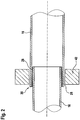
Figur 2 schematisch einen Schnitt durch die Abgasanlage an einer Verbindungsstelle, die in einer Haltevorrichtung aufgenommen ist; -
Figur 3 schematisch das Detail III vonFigur 1 ; -
Figur 4 schematisch im Schnitt eine Verbindungsstelle während des Kalibrierens; und -
Figur 5 schematisch im Schnitt eine Verbindungsstelle beim Verlöten. - In
Figur 1 ist schematisch eine Abgasanlage gezeigt, die einen Anschlussflansch 12 enthält, mehrere Rohrbögen 14, mehrere Rohrabschnitte 16, mehrere Muffen 18 sowie ein Katalysatorgehäuse 20 und einen Schalldämpfer 22. Bei den Rohrabschnitten 16 sowie den Rohrbögen 14 und den Muffen 18, die hier auch als "Rohrabschnitte" angesehen werden, handelt es sich um vorgefertigte Teile eines Baukastensystems, aus dem für den jeweiligen Fahrzeugtyp diejenigen Teile ausgewählt werden, mit denen der gewünschten Rohrverlauf, die gewünschten Abmessungen, etc. erhalten werden können. Alle Rohrabschnitte bestehen aus Blech, wobei Wandstärken im Bereich bis hinunter zu 0,6 mm möglich sind. - Die Rohrabschnitte sind jeweils ineinandergesteckt, so dass eine Vielzahl von Verbindungsstellen 30 gebildet ist (siehe auch die
Figuren 2 und3 ). Alle Rohrabschnitte sind dabei so dimensioniert, dass sie mit einer Spielpassung ineinandergesteckt werden können. Dies ermöglicht, die gesamte Abgasanlage mit geringem Aufwand auf einem Montagetisch 40 vorzumontieren, wobei jeder Verbindungsstelle eine Haltevorrichtung 42 zugeordnet ist. Die Aufgabe der Haltevorrichtung 42 besteht im ersten Schritt darin, die Rohrabschnitte geeignet zu fixieren. - Wie in
Figur 4 gezeigt ist, liegt bei der lose zusammengesteckten Abgasanlage, also im vormontierten Zustand, ein vergleichsweise großes Spiel S im Bereich einer Verbindungsstelle 30 vor (hier beispielhaft dargestellt für eine Verbindungsstelle zwischen einer Muffe 18 und einem Rohrabschnitt 16). Dieses Spiel S ermöglicht es, die Rohrabschnitte problemlos ineinanderzustecken, ohne dass sich die einzelnen Bauteile verklemmen oder größere Kräfte aufgewendet werden müssen. - Um die einzelnen Rohrabschnitte im Bereich der entsprechenden Verbindungsstellen 30 aneinander zu befestigen, wird die entsprechende Verbindungsstelle 30 zunächst kalibriert. Dies ist schematisch in
Figur 4 dargestellt, in der mehrere Pressbacken 44 gezeigt sind, die einen radial nach innen wirkenden Druck auf den außenliegenden Rohrabschnitt, hier die Muffe 18, und damit indirekt auch auf den innenliegenden Rohrabschnitt ausüben. Die aufgebrachte Kraft ist so hoch, dass zumindest der außenliegende Rohrabschnitt plastisch verformt wird, also nach dem Kalibrieren einen geringeren Innendurchmesser hat als vorher. Dies gewährleistet, dass nach dem Kalibrieren ein vergleichsweise enger Spalt (siehe den kleineren Spalt S inFigur 5 ) vorliegt, der es ermöglicht, die Rohrabschnitte zuverlässig miteinander zu verlöten. - Die Pressbacken 44 können an der Haltevorrichtung angebracht oder in diese integriert sein. Beispielsweise kann jeder Haltevorrichtung eine Kalibrierzange zugeordnet sein, die sich um die Verbindungsstelle 30 schließt und dort den nötigen Druck aufbringt.
- Zum Zwecke des Verlötens kann im Bereich der Verbindungsstelle ein Lotring aus einem Lotmaterial, insbesondere Hochtemperaturlotmaterial, angeordnet werden. Alternativ und bevorzugt ist vorgesehen, dass mindestens einer der Rohrabschnitte im Bereich der Verbindungsstelle mit einem Lotmaterial beschichtet ist, insbesondere mit einer aufgedruckten oder in ähnlicher Weise aufgebrachten Lotpaste (siehe das in den
Figuren 2 und3 schematisch angedeutete Lotmaterial 28). Zum Verlöten der Rohrabschnitte ist dann vorgesehen, dass nach dem Kalibrieren die Verbindungsstelle 30 erwärmt wird, insbesondere durch eine Induktionsvorrichtung 46 (sieheFigur 5 ), mit der die Verbindungsstelle 30 so erhitzt werden kann, dass das Lotmaterial aufschmilzt und die beiden Rohrabschnitte nach dem Abkühlen zuverlässig miteinander verbindet. - Auch die Induktionsvorrichtung 46 ist vorzugsweise in die Haltevorrichtung 42 integriert, so dass nach dem Aufspannen der Abgasanlage auf dem Montagetisch 40 automatisiert erst der Kalibrierschritt und dann der Lötschritt vorgenommen werden können, während die Abgasanlage auf dem Montagetisch fixiert bleibt.
- Besonders vorteilhaft hinsichtlich der Produktivität ist es, dass die gesamte Abgasanlage horizontal vormontiert werden kann und außerdem alle Verbindungsstellen gleichzeitig verlötet werden können. Es ist dabei ohne Einfluss, dass je nach konkretem Typ der Abgasanlage eine sehr hohe Anzahl von Verbindungsstellen 30 vorhanden ist, insbesondere zehn oder mehr Verbindungsstellen.
Claims (8)
- Verfahren zur Herstellung einer Abgasanlage (10) mit mehreren Rohrabschnitten (14, 16, 18) mittels der folgenden Schritte:- die gesamte Abgasanlage (10) wird zusammengesteckt, wobei die Rohrabschnitte (14, 16, 18) mit einer Spielpassung ineinandergesteckt werden, so dass Verbindungsstellen (30) gebildet sind, an denen sich jeweils zwei Rohrabschnitte (14, 16, 18) überlappen;- die Rohrabschnitte (14, 16, 18) werden an allen Verbindungsstellen (30) im Wesentlichen gleichzeitig kalibriert, so dass sich jeweils ein enger Spalt ergibt;- alle Verbindungsstellen (30) der Abgasanlage (10) werden im Wesentlichen gleichzeitig verlötet.
- Verfahren nach Anspruch 1, dadurch gekennzeichnet, dass beim Kalibrieren ein Druck in radialer Richtung nach innen auf das außenliegende Rohr aufgebracht wird, so dass mindestens das außenliegende Rohr plastisch verformt wird.
- Verfahren nach einem der vorhergehenden Ansprüche, dadurch gekennzeichnet, dass die Abgasanlage (10) in horizontaler Ausrichtung verlötet wird.
- Verfahren nach einem der vorhergehenden Ansprüche, dadurch gekennzeichnet, dass vor dem Zusammenstecken an einem Ende eines Rohrabschnitts (14, 16, 18) ein Lotmaterial (28) aufgebracht wurde.
- Verfahren nach einem der vorhergehenden Ansprüche, dadurch gekennzeichnet, dass mehr als fünf unterschiedliche Rohrabschnitte (14, 16, 18) verwendet sind.
- Verfahren nach Anspruch 5, dadurch gekennzeichnet, dass mehr als zehn unterschiedliche Rohrabschnitte (14, 16, 18) verwendet sind.
- Verfahren nach einem der vorhergehenden Ansprüche, dadurch gekennzeichnet, dass als einer der Rohrabschnitte eine Muffe (18) verwendet wird.
- Verfahren nach Anspruch 7, dadurch gekennzeichnet, dass gerade Rohrabschnitte (14) mit dazwischen angeordneten, gekrümmten Muffen (18) verwendet werden.
Applications Claiming Priority (2)
| Application Number | Priority Date | Filing Date | Title |
|---|---|---|---|
| DE102011106801A DE102011106801A1 (de) | 2011-07-06 | 2011-07-06 | Verfahren zur Herstellung einer Abgasanlage sowie Abgasanlage |
| PCT/EP2012/002651 WO2013004352A1 (de) | 2011-07-06 | 2012-06-22 | Verfahren zur herstellung einer abgasanlage sowie abgasanlage |
Publications (2)
| Publication Number | Publication Date |
|---|---|
| EP2729679A1 EP2729679A1 (de) | 2014-05-14 |
| EP2729679B1 true EP2729679B1 (de) | 2019-05-01 |
Family
ID=46354150
Family Applications (1)
| Application Number | Title | Priority Date | Filing Date |
|---|---|---|---|
| EP12729361.1A Active EP2729679B1 (de) | 2011-07-06 | 2012-06-22 | Verfahren zur herstellung einer abgasanlage sowie abgasanlage |
Country Status (6)
| Country | Link |
|---|---|
| US (1) | US9752708B2 (de) |
| EP (1) | EP2729679B1 (de) |
| KR (1) | KR101804617B1 (de) |
| CN (1) | CN103649484B (de) |
| DE (1) | DE102011106801A1 (de) |
| WO (1) | WO2013004352A1 (de) |
Families Citing this family (6)
| Publication number | Priority date | Publication date | Assignee | Title |
|---|---|---|---|---|
| DE202013104875U1 (de) * | 2013-10-31 | 2015-02-02 | Witzenmann Gmbh | Verbindung von Leitungselementen |
| CN106499491B (zh) * | 2016-09-27 | 2019-01-25 | 奇瑞汽车股份有限公司 | 一种碳纤维复合材料汽车排气管尾管及其制造方法 |
| DE102017101858A1 (de) * | 2017-01-31 | 2018-08-02 | Faurecia Emissions Control Technologies, Germany Gmbh | Abgassystem-Spannvorrichtung, Fügevorrichtung für ein Abgassystem, Verfahren zum Spannen sowie Verfahren zum Fügen |
| DE102017105821A1 (de) | 2017-03-17 | 2018-09-20 | Faurecia Emissions Control Technologies, Germany Gmbh | Fügevorrichtung und Verfahren zum Herstellen eines Abgassystems |
| ES2951912T3 (es) * | 2019-02-18 | 2023-10-25 | Tata Steel Nederland Tech Bv | Sección de tubo para sistema de transporte de tubo evacuado |
| CN116765536B (zh) * | 2022-03-08 | 2025-09-30 | 浙江盾安禾田金属有限公司 | 阀体焊接系统及阀体焊接方法 |
Citations (1)
| Publication number | Priority date | Publication date | Assignee | Title |
|---|---|---|---|---|
| DE8632790U1 (de) * | 1986-12-06 | 1987-02-19 | Witzenmann GmbH, Metallschlauch-Fabrik Pforzheim, 7530 Pforzheim | Schweißvorrichtung zwischen einem Metallbalg und einem Metallrohr |
Family Cites Families (14)
| Publication number | Priority date | Publication date | Assignee | Title |
|---|---|---|---|---|
| EP0662564B2 (de) | 1994-01-07 | 2001-09-26 | J. Eberspächer GmbH & Co. | Luftspaltisoliertes Abgasrohr und Verfahren zu seiner Herstellung |
| DE29521672U1 (de) * | 1995-06-14 | 1998-02-12 | NiroSan Gebäudetechnik Vertriebs-GmbH, 51545 Waldbröl | Muffenverbindung |
| WO2002031326A1 (fr) | 2000-10-11 | 2002-04-18 | Honda Giken Kogyo Kabushiki Kaisha | Systeme d'echappement pour moteur thermique |
| DE102004038099A1 (de) | 2004-08-05 | 2006-02-23 | Zeuna-Stärker GmbH & Co. KG | Abgasanlage sowie Verfahren zum Verbinden von Komponenten einer Abgasanlage |
| DE102005012067A1 (de) * | 2005-03-16 | 2006-10-12 | Emitec Gesellschaft Für Emissionstechnologie Mbh | Gehäuse für eine Abgasbehandlungskomponente mit Verstärkungshülse |
| DE102005022512A1 (de) * | 2005-05-11 | 2006-11-16 | J. Eberspächer GmbH & Co. KG | Herstellungsverfahren für eine Abgasbehandlungsvorrichtung |
| DE102005044810A1 (de) | 2005-09-20 | 2007-03-29 | Arvinmeritor Emissions Technologies Gmbh | Gehäuse für eine Abgasreinigungsvorrichtung |
| DE102006021674B4 (de) * | 2006-05-10 | 2014-05-15 | Tenneco Gmbh | Verfahren zum Herstellen von Abgaskrümmern |
| DE102007032267B4 (de) * | 2007-07-11 | 2018-01-18 | Emcon Technologies Germany (Augsburg) Gmbh | Abgasanlagen-Rohr mit maßgeschneiderter Wandstärke |
| JP2009052539A (ja) * | 2007-08-01 | 2009-03-12 | Futaba Industrial Co Ltd | 排気管接続構造及び排気管接続方法 |
| DE102007060398B4 (de) * | 2007-12-14 | 2016-10-06 | GM Global Technology Operations LLC (n. d. Ges. d. Staates Delaware) | Auspuff eines Kraftfahrzeugs |
| DE102007062659A1 (de) | 2007-12-24 | 2009-06-25 | J. Eberspächer GmbH & Co. KG | Abgassammler und zugehöriges Herstellungsverfahren |
| JP5608665B2 (ja) * | 2008-11-11 | 2014-10-15 | テネコ オートモティブ オペレーティング カンパニー インコーポレイテッド | 排気ガスを処理する触媒ユニットの製造方法 |
| DE102009059686A1 (de) * | 2009-12-19 | 2011-06-22 | Umicore AG & Co. KG, 63457 | Legierung |
-
2011
- 2011-07-06 DE DE102011106801A patent/DE102011106801A1/de not_active Ceased
-
2012
- 2012-06-22 EP EP12729361.1A patent/EP2729679B1/de active Active
- 2012-06-22 KR KR1020147000976A patent/KR101804617B1/ko active Active
- 2012-06-22 US US14/130,745 patent/US9752708B2/en active Active
- 2012-06-22 CN CN201280033620.4A patent/CN103649484B/zh active Active
- 2012-06-22 WO PCT/EP2012/002651 patent/WO2013004352A1/de not_active Ceased
Patent Citations (1)
| Publication number | Priority date | Publication date | Assignee | Title |
|---|---|---|---|---|
| DE8632790U1 (de) * | 1986-12-06 | 1987-02-19 | Witzenmann GmbH, Metallschlauch-Fabrik Pforzheim, 7530 Pforzheim | Schweißvorrichtung zwischen einem Metallbalg und einem Metallrohr |
Also Published As
| Publication number | Publication date |
|---|---|
| WO2013004352A1 (de) | 2013-01-10 |
| US20140197631A1 (en) | 2014-07-17 |
| CN103649484B (zh) | 2016-06-15 |
| KR20140048203A (ko) | 2014-04-23 |
| US9752708B2 (en) | 2017-09-05 |
| EP2729679A1 (de) | 2014-05-14 |
| CN103649484A (zh) | 2014-03-19 |
| DE102011106801A1 (de) | 2013-01-10 |
| KR101804617B1 (ko) | 2017-12-04 |
Similar Documents
| Publication | Publication Date | Title |
|---|---|---|
| EP1888891B1 (de) | Fahrzeugschalldämpfer | |
| EP1774147B1 (de) | Abgasanlage sowie verfahren zum verbinden von komponenten einer abgasanlage | |
| DE69804007T2 (de) | Verfahren zum zusammensetzen von wärmetauscher | |
| EP2986402B1 (de) | Verfahren zum herstellen eines mehrlagigen grossrohres | |
| DE19923557B4 (de) | Gebauter luftspaltisolierter Abgaskrümmer einer Abgasanlage eines Kraftfahrzeuges und ein Verfahren zu dessen Herstellung | |
| WO2013004352A1 (de) | Verfahren zur herstellung einer abgasanlage sowie abgasanlage | |
| DE102016100470A1 (de) | Baugruppe mit mindestens zwei Bauteilen einer Abgasanlage und Verfahren zum Fügen | |
| EP1770250B1 (de) | Wärmetauscher für Abgasleitungen | |
| EP0292754B1 (de) | Flansch zur Befestigung von Rohren | |
| EP2205371B1 (de) | Verfahren zur herstellung von rohr-in-rohr-systemen | |
| EP2915973B1 (de) | Trichter-Rohr-Anordnung | |
| WO2012136355A1 (de) | Abgas führende vorrichtung und verfahren zu ihrer herstellung | |
| DE19543603A1 (de) | Anordnung zur Schweißverbindung eines Grundelementes mit einem anderen Bauteil aus Stahl | |
| DE19501780C2 (de) | Rohr-Flansch-Verbindung | |
| EP3088834A1 (de) | Wärmeübertrager | |
| DE102009013222B3 (de) | Hohlkörper und Verfahren seiner Herstellung | |
| DE4216090A1 (de) | Verfahren zum Herstellen eines Abgasrohrs und Abgasrohr | |
| DE102007036205B4 (de) | Verfahren zum Herstellen einer luftspaltisolierten Rohreinheit und Abgasrohreinheit | |
| AT406453B (de) | Verfahren zur herstellung eines rohrendes mit einem bund | |
| DE4402020C2 (de) | Verfahren und Anlage zur Herstellung von Wärmetauschern für fluide Wärmeträger sowie druckfester Wärmetausch | |
| DE102004024831A1 (de) | Verfahren zum Herstellen einer Flanschanbindung und Abgasstrang-Flanschanbindung | |
| DE102006034865B4 (de) | Verfahren zum Verbinden einer Flanschplatte mit einem abgasführenden Rohr und Flansch-Rohr-Verbindung | |
| DE2921938A1 (de) | Auspuffschalldaempfer und verfahren zur befestigung eines rohrstutzens an einem schalldaempfertopf | |
| DE19813213A1 (de) | Heizkörperverrohrungsstück | |
| DE102021201154A1 (de) | Montageverfahren eines Zulauftrichters sowie zugehöriger Zulauftrichter und Kolben |
Legal Events
| Date | Code | Title | Description |
|---|---|---|---|
| PUAI | Public reference made under article 153(3) epc to a published international application that has entered the european phase |
Free format text: ORIGINAL CODE: 0009012 |
|
| 17P | Request for examination filed |
Effective date: 20140131 |
|
| AK | Designated contracting states |
Kind code of ref document: A1 Designated state(s): AL AT BE BG CH CY CZ DE DK EE ES FI FR GB GR HR HU IE IS IT LI LT LU LV MC MK MT NL NO PL PT RO RS SE SI SK SM TR |
|
| DAX | Request for extension of the european patent (deleted) | ||
| STAA | Information on the status of an ep patent application or granted ep patent |
Free format text: STATUS: EXAMINATION IS IN PROGRESS |
|
| 17Q | First examination report despatched |
Effective date: 20170208 |
|
| GRAP | Despatch of communication of intention to grant a patent |
Free format text: ORIGINAL CODE: EPIDOSNIGR1 |
|
| STAA | Information on the status of an ep patent application or granted ep patent |
Free format text: STATUS: GRANT OF PATENT IS INTENDED |
|
| INTG | Intention to grant announced |
Effective date: 20181119 |
|
| GRAS | Grant fee paid |
Free format text: ORIGINAL CODE: EPIDOSNIGR3 |
|
| GRAA | (expected) grant |
Free format text: ORIGINAL CODE: 0009210 |
|
| STAA | Information on the status of an ep patent application or granted ep patent |
Free format text: STATUS: THE PATENT HAS BEEN GRANTED |
|
| AK | Designated contracting states |
Kind code of ref document: B1 Designated state(s): AL AT BE BG CH CY CZ DE DK EE ES FI FR GB GR HR HU IE IS IT LI LT LU LV MC MK MT NL NO PL PT RO RS SE SI SK SM TR |
|
| REG | Reference to a national code |
Ref country code: GB Ref legal event code: FG4D Free format text: NOT ENGLISH |
|
| REG | Reference to a national code |
Ref country code: CH Ref legal event code: EP Ref country code: AT Ref legal event code: REF Ref document number: 1127198 Country of ref document: AT Kind code of ref document: T Effective date: 20190515 |
|
| REG | Reference to a national code |
Ref country code: DE Ref legal event code: R096 Ref document number: 502012014693 Country of ref document: DE |
|
| REG | Reference to a national code |
Ref country code: IE Ref legal event code: FG4D Free format text: LANGUAGE OF EP DOCUMENT: GERMAN |
|
| REG | Reference to a national code |
Ref country code: NL Ref legal event code: MP Effective date: 20190501 |
|
| REG | Reference to a national code |
Ref country code: LT Ref legal event code: MG4D |
|
| PG25 | Lapsed in a contracting state [announced via postgrant information from national office to epo] |
Ref country code: FI Free format text: LAPSE BECAUSE OF FAILURE TO SUBMIT A TRANSLATION OF THE DESCRIPTION OR TO PAY THE FEE WITHIN THE PRESCRIBED TIME-LIMIT Effective date: 20190501 Ref country code: NO Free format text: LAPSE BECAUSE OF FAILURE TO SUBMIT A TRANSLATION OF THE DESCRIPTION OR TO PAY THE FEE WITHIN THE PRESCRIBED TIME-LIMIT Effective date: 20190801 Ref country code: LT Free format text: LAPSE BECAUSE OF FAILURE TO SUBMIT A TRANSLATION OF THE DESCRIPTION OR TO PAY THE FEE WITHIN THE PRESCRIBED TIME-LIMIT Effective date: 20190501 Ref country code: NL Free format text: LAPSE BECAUSE OF FAILURE TO SUBMIT A TRANSLATION OF THE DESCRIPTION OR TO PAY THE FEE WITHIN THE PRESCRIBED TIME-LIMIT Effective date: 20190501 Ref country code: PT Free format text: LAPSE BECAUSE OF FAILURE TO SUBMIT A TRANSLATION OF THE DESCRIPTION OR TO PAY THE FEE WITHIN THE PRESCRIBED TIME-LIMIT Effective date: 20190901 Ref country code: ES Free format text: LAPSE BECAUSE OF FAILURE TO SUBMIT A TRANSLATION OF THE DESCRIPTION OR TO PAY THE FEE WITHIN THE PRESCRIBED TIME-LIMIT Effective date: 20190501 Ref country code: HR Free format text: LAPSE BECAUSE OF FAILURE TO SUBMIT A TRANSLATION OF THE DESCRIPTION OR TO PAY THE FEE WITHIN THE PRESCRIBED TIME-LIMIT Effective date: 20190501 Ref country code: SE Free format text: LAPSE BECAUSE OF FAILURE TO SUBMIT A TRANSLATION OF THE DESCRIPTION OR TO PAY THE FEE WITHIN THE PRESCRIBED TIME-LIMIT Effective date: 20190501 Ref country code: AL Free format text: LAPSE BECAUSE OF FAILURE TO SUBMIT A TRANSLATION OF THE DESCRIPTION OR TO PAY THE FEE WITHIN THE PRESCRIBED TIME-LIMIT Effective date: 20190501 |
|
| PG25 | Lapsed in a contracting state [announced via postgrant information from national office to epo] |
Ref country code: LV Free format text: LAPSE BECAUSE OF FAILURE TO SUBMIT A TRANSLATION OF THE DESCRIPTION OR TO PAY THE FEE WITHIN THE PRESCRIBED TIME-LIMIT Effective date: 20190501 Ref country code: GR Free format text: LAPSE BECAUSE OF FAILURE TO SUBMIT A TRANSLATION OF THE DESCRIPTION OR TO PAY THE FEE WITHIN THE PRESCRIBED TIME-LIMIT Effective date: 20190802 Ref country code: RS Free format text: LAPSE BECAUSE OF FAILURE TO SUBMIT A TRANSLATION OF THE DESCRIPTION OR TO PAY THE FEE WITHIN THE PRESCRIBED TIME-LIMIT Effective date: 20190501 Ref country code: BG Free format text: LAPSE BECAUSE OF FAILURE TO SUBMIT A TRANSLATION OF THE DESCRIPTION OR TO PAY THE FEE WITHIN THE PRESCRIBED TIME-LIMIT Effective date: 20190801 |
|
| PG25 | Lapsed in a contracting state [announced via postgrant information from national office to epo] |
Ref country code: IS Free format text: LAPSE BECAUSE OF FAILURE TO SUBMIT A TRANSLATION OF THE DESCRIPTION OR TO PAY THE FEE WITHIN THE PRESCRIBED TIME-LIMIT Effective date: 20190901 |
|
| PG25 | Lapsed in a contracting state [announced via postgrant information from national office to epo] |
Ref country code: RO Free format text: LAPSE BECAUSE OF FAILURE TO SUBMIT A TRANSLATION OF THE DESCRIPTION OR TO PAY THE FEE WITHIN THE PRESCRIBED TIME-LIMIT Effective date: 20190501 Ref country code: CZ Free format text: LAPSE BECAUSE OF FAILURE TO SUBMIT A TRANSLATION OF THE DESCRIPTION OR TO PAY THE FEE WITHIN THE PRESCRIBED TIME-LIMIT Effective date: 20190501 Ref country code: SK Free format text: LAPSE BECAUSE OF FAILURE TO SUBMIT A TRANSLATION OF THE DESCRIPTION OR TO PAY THE FEE WITHIN THE PRESCRIBED TIME-LIMIT Effective date: 20190501 Ref country code: MC Free format text: LAPSE BECAUSE OF FAILURE TO SUBMIT A TRANSLATION OF THE DESCRIPTION OR TO PAY THE FEE WITHIN THE PRESCRIBED TIME-LIMIT Effective date: 20190501 Ref country code: EE Free format text: LAPSE BECAUSE OF FAILURE TO SUBMIT A TRANSLATION OF THE DESCRIPTION OR TO PAY THE FEE WITHIN THE PRESCRIBED TIME-LIMIT Effective date: 20190501 Ref country code: DK Free format text: LAPSE BECAUSE OF FAILURE TO SUBMIT A TRANSLATION OF THE DESCRIPTION OR TO PAY THE FEE WITHIN THE PRESCRIBED TIME-LIMIT Effective date: 20190501 |
|
| REG | Reference to a national code |
Ref country code: CH Ref legal event code: PL |
|
| REG | Reference to a national code |
Ref country code: DE Ref legal event code: R097 Ref document number: 502012014693 Country of ref document: DE |
|
| PG25 | Lapsed in a contracting state [announced via postgrant information from national office to epo] |
Ref country code: SM Free format text: LAPSE BECAUSE OF FAILURE TO SUBMIT A TRANSLATION OF THE DESCRIPTION OR TO PAY THE FEE WITHIN THE PRESCRIBED TIME-LIMIT Effective date: 20190501 Ref country code: IT Free format text: LAPSE BECAUSE OF FAILURE TO SUBMIT A TRANSLATION OF THE DESCRIPTION OR TO PAY THE FEE WITHIN THE PRESCRIBED TIME-LIMIT Effective date: 20190501 |
|
| PLBE | No opposition filed within time limit |
Free format text: ORIGINAL CODE: 0009261 |
|
| STAA | Information on the status of an ep patent application or granted ep patent |
Free format text: STATUS: NO OPPOSITION FILED WITHIN TIME LIMIT |
|
| REG | Reference to a national code |
Ref country code: BE Ref legal event code: MM Effective date: 20190630 |
|
| PG25 | Lapsed in a contracting state [announced via postgrant information from national office to epo] |
Ref country code: TR Free format text: LAPSE BECAUSE OF FAILURE TO SUBMIT A TRANSLATION OF THE DESCRIPTION OR TO PAY THE FEE WITHIN THE PRESCRIBED TIME-LIMIT Effective date: 20190501 |
|
| 26N | No opposition filed |
Effective date: 20200204 |
|
| GBPC | Gb: european patent ceased through non-payment of renewal fee |
Effective date: 20190801 |
|
| PG25 | Lapsed in a contracting state [announced via postgrant information from national office to epo] |
Ref country code: PL Free format text: LAPSE BECAUSE OF FAILURE TO SUBMIT A TRANSLATION OF THE DESCRIPTION OR TO PAY THE FEE WITHIN THE PRESCRIBED TIME-LIMIT Effective date: 20190501 Ref country code: IE Free format text: LAPSE BECAUSE OF NON-PAYMENT OF DUE FEES Effective date: 20190622 |
|
| PG25 | Lapsed in a contracting state [announced via postgrant information from national office to epo] |
Ref country code: BE Free format text: LAPSE BECAUSE OF NON-PAYMENT OF DUE FEES Effective date: 20190630 Ref country code: LU Free format text: LAPSE BECAUSE OF NON-PAYMENT OF DUE FEES Effective date: 20190622 Ref country code: SI Free format text: LAPSE BECAUSE OF FAILURE TO SUBMIT A TRANSLATION OF THE DESCRIPTION OR TO PAY THE FEE WITHIN THE PRESCRIBED TIME-LIMIT Effective date: 20190501 Ref country code: LI Free format text: LAPSE BECAUSE OF NON-PAYMENT OF DUE FEES Effective date: 20190630 Ref country code: CH Free format text: LAPSE BECAUSE OF NON-PAYMENT OF DUE FEES Effective date: 20190630 |
|
| REG | Reference to a national code |
Ref country code: AT Ref legal event code: MM01 Ref document number: 1127198 Country of ref document: AT Kind code of ref document: T Effective date: 20190622 |
|
| PG25 | Lapsed in a contracting state [announced via postgrant information from national office to epo] |
Ref country code: GB Free format text: LAPSE BECAUSE OF NON-PAYMENT OF DUE FEES Effective date: 20190801 |
|
| PG25 | Lapsed in a contracting state [announced via postgrant information from national office to epo] |
Ref country code: AT Free format text: LAPSE BECAUSE OF NON-PAYMENT OF DUE FEES Effective date: 20190622 |
|
| PG25 | Lapsed in a contracting state [announced via postgrant information from national office to epo] |
Ref country code: CY Free format text: LAPSE BECAUSE OF FAILURE TO SUBMIT A TRANSLATION OF THE DESCRIPTION OR TO PAY THE FEE WITHIN THE PRESCRIBED TIME-LIMIT Effective date: 20190501 |
|
| PG25 | Lapsed in a contracting state [announced via postgrant information from national office to epo] |
Ref country code: MT Free format text: LAPSE BECAUSE OF FAILURE TO SUBMIT A TRANSLATION OF THE DESCRIPTION OR TO PAY THE FEE WITHIN THE PRESCRIBED TIME-LIMIT Effective date: 20190501 Ref country code: HU Free format text: LAPSE BECAUSE OF FAILURE TO SUBMIT A TRANSLATION OF THE DESCRIPTION OR TO PAY THE FEE WITHIN THE PRESCRIBED TIME-LIMIT; INVALID AB INITIO Effective date: 20120622 |
|
| PG25 | Lapsed in a contracting state [announced via postgrant information from national office to epo] |
Ref country code: MK Free format text: LAPSE BECAUSE OF FAILURE TO SUBMIT A TRANSLATION OF THE DESCRIPTION OR TO PAY THE FEE WITHIN THE PRESCRIBED TIME-LIMIT Effective date: 20190501 |
|
| PGFP | Annual fee paid to national office [announced via postgrant information from national office to epo] |
Ref country code: DE Payment date: 20250520 Year of fee payment: 14 |
|
| PGFP | Annual fee paid to national office [announced via postgrant information from national office to epo] |
Ref country code: FR Payment date: 20250520 Year of fee payment: 14 |