EP2729207B1 - Trockenpulverinhalator - Google Patents
Trockenpulverinhalator Download PDFInfo
- Publication number
- EP2729207B1 EP2729207B1 EP11773488.9A EP11773488A EP2729207B1 EP 2729207 B1 EP2729207 B1 EP 2729207B1 EP 11773488 A EP11773488 A EP 11773488A EP 2729207 B1 EP2729207 B1 EP 2729207B1
- Authority
- EP
- European Patent Office
- Prior art keywords
- capsule
- cap
- opening
- knurled wheel
- dispersion chamber
- Prior art date
- Legal status (The legal status is an assumption and is not a legal conclusion. Google has not performed a legal analysis and makes no representation as to the accuracy of the status listed.)
- Active
Links
Images



Classifications
-
- A—HUMAN NECESSITIES
- A61—MEDICAL OR VETERINARY SCIENCE; HYGIENE
- A61M—DEVICES FOR INTRODUCING MEDIA INTO, OR ONTO, THE BODY; DEVICES FOR TRANSDUCING BODY MEDIA OR FOR TAKING MEDIA FROM THE BODY; DEVICES FOR PRODUCING OR ENDING SLEEP OR STUPOR
- A61M15/00—Inhalators
- A61M15/0028—Inhalators using prepacked dosages, one for each application, e.g. capsules to be perforated or broken-up
-
- A—HUMAN NECESSITIES
- A61—MEDICAL OR VETERINARY SCIENCE; HYGIENE
- A61M—DEVICES FOR INTRODUCING MEDIA INTO, OR ONTO, THE BODY; DEVICES FOR TRANSDUCING BODY MEDIA OR FOR TAKING MEDIA FROM THE BODY; DEVICES FOR PRODUCING OR ENDING SLEEP OR STUPOR
- A61M15/00—Inhalators
- A61M15/0028—Inhalators using prepacked dosages, one for each application, e.g. capsules to be perforated or broken-up
- A61M15/003—Inhalators using prepacked dosages, one for each application, e.g. capsules to be perforated or broken-up using capsules, e.g. to be perforated or broken-up
-
- A—HUMAN NECESSITIES
- A61—MEDICAL OR VETERINARY SCIENCE; HYGIENE
- A61M—DEVICES FOR INTRODUCING MEDIA INTO, OR ONTO, THE BODY; DEVICES FOR TRANSDUCING BODY MEDIA OR FOR TAKING MEDIA FROM THE BODY; DEVICES FOR PRODUCING OR ENDING SLEEP OR STUPOR
- A61M15/00—Inhalators
- A61M15/0028—Inhalators using prepacked dosages, one for each application, e.g. capsules to be perforated or broken-up
- A61M15/003—Inhalators using prepacked dosages, one for each application, e.g. capsules to be perforated or broken-up using capsules, e.g. to be perforated or broken-up
- A61M15/0031—Inhalators using prepacked dosages, one for each application, e.g. capsules to be perforated or broken-up using capsules, e.g. to be perforated or broken-up by bursting or breaking the package, i.e. without cutting or piercing
-
- A—HUMAN NECESSITIES
- A61—MEDICAL OR VETERINARY SCIENCE; HYGIENE
- A61M—DEVICES FOR INTRODUCING MEDIA INTO, OR ONTO, THE BODY; DEVICES FOR TRANSDUCING BODY MEDIA OR FOR TAKING MEDIA FROM THE BODY; DEVICES FOR PRODUCING OR ENDING SLEEP OR STUPOR
- A61M2202/00—Special media to be introduced, removed or treated
- A61M2202/06—Solids
- A61M2202/064—Powder
-
- A—HUMAN NECESSITIES
- A61—MEDICAL OR VETERINARY SCIENCE; HYGIENE
- A61M—DEVICES FOR INTRODUCING MEDIA INTO, OR ONTO, THE BODY; DEVICES FOR TRANSDUCING BODY MEDIA OR FOR TAKING MEDIA FROM THE BODY; DEVICES FOR PRODUCING OR ENDING SLEEP OR STUPOR
- A61M2206/00—Characteristics of a physical parameter; associated device therefor
- A61M2206/10—Flow characteristics
- A61M2206/16—Rotating swirling helical flow, e.g. by tangential inflows
Definitions
- the present invention relates to a dry powder inhaler.
- Inhalers are well known in the state of the art. There are different kinds.
- a first type of inhaler contains a reservoir receiving a multitude of doses of powder, the inhaler being provided with dosing means allowing each actuation to separate a dose of this powder from the reservoir to bring it into an expulsion conduit to to be distributed to the user.
- Another type of inhaler consists in arranging the doses of powder in pre-dosed individual reservoirs and then opening one of these reservoirs each time the inhaler is actuated. This implementation ensures a better seal of the powder, since each dose is open only at the time of its expulsion.
- various variants have already been proposed, such as an elongated blister strip or blisters arranged on a rotating circular disk.
- inhalers comprising individual reservoirs, such as capsules or capsules, which are to be loaded into the inhaler just before use thereof.
- the advantage of these devices is that it is not necessary to store all the doses inside the device, so that it can be reduced in size.
- the use is more complex, since the user is obliged to load a capsule in the inhaler before each use.
- other disadvantages specific to these capsule inhalers have appeared.
- these devices are generally made of two parts, one being provided with the mouthpiece. When handling these devices, to open the capsule and release the powder, or to empty the empty capsule after inhalation, the fingers of the user generally come into contact with the mouthpiece, which may present risks of contamination .
- the upper part of the capsule is generally stuck in the loading opening after opening of the capsule, generally made by separating the lower capsule portion. It is only when the user introduces the next capsule into the loading opening that he will expel this upper part. This can have disadvantages, especially when there is time between two uses of the device.
- the documents US 2004/255940 A1 , US 4,206,758 A , EP 0 271 029 A2 , US 4,353,365 A and DE 197 42 994 A1 disclose dry powder inhalers according to the prior art.
- the document US 2004/255940 A1 discloses an inhaler according to the preamble of claim 1.
- the present invention aims to provide a dry powder inhaler, which does not reproduce the aforementioned drawbacks.
- the present invention aims to provide such an inhaler that is simple and inexpensive to manufacture and assemble, reliable use, and limiting as much as possible the risk of contamination and / or pollution.
- the present invention therefore relates to a dry powder inhaler according to claim 1.
- said cap has an opening aligned with the loading aperture of the wheel in capsule loading position.
- said opening is disposed at the bottom of a bowl facilitating manual insertion of the capsule into the loading aperture of the wheel.
- said wheel is rotatable in both directions relative to said body to open said capsule.
- said dispersion chamber has air inlets to create additional air flow during inhalation to further swirl the powder in the dispersion chamber before inhalation.
- said air inlets are made approximately tangentially in the cylindrical wall of the body.
- said mouthpiece is provided with a grid to prevent the expulsion of the capsule parts through said dispensing orifice.
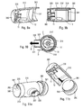
- the figures illustrate an advantageous embodiment of the present invention.
- the figure 1 illustrates in particular an exploded perspective view of the device.
- the inhaler 300 consists of only four pieces.
- the device of the invention is intended for receiving a capsule or capsule 10, formed of two parts 11, 12 nested one inside the other, and containing a dose of powder.
- a hollow body 310 of substantially cylindrical shape, with respect to a longitudinal axis, is provided on its periphery with a mouthpiece 330 defining the dispensing orifice 331.
- the interior of the body 310 defines a dispersion chamber 311.
- the body 310 is made of transparent or translucent material, preferably tinted, to allow viewing the interior of the dispersion chamber 311 from the outside.
- This body 310 is open on these two axial sides.
- the body 310 comprises a central hollow sleeve 314 fixed to the body by two lateral spacers 312 and 313. These spacers each form a capsule opening profile, as will be explained below.
- the hollow sleeve 314 has two axial cuts 317.
- air passage holes 318 are formed in the cylindrical wall of the body 310 to create air inlets in the dispersion chamber 311. These air inlets are approximately tangential, and are intended in particular to promote the good distribution of the powder at each inhalation.
- five holes can be provided, three of which are visible on the figure 4b .
- these passage holes 318 are formed at the level of diametrically opposite longitudinal shoulders, formed in the cylindrical internal surface of the body 310. These shoulders 318 ', visible in particular on the Figures 5d and 5e , strengthen the body at the passage holes and promotes swirling in the dispersion chamber.
- different air inlets and any number of air inlets are also possible.
- a wheel 370 is fixed to the body 310 on the first axial side thereof, and a cap 360 is fixed on the second axial side. This wheel 370 and cap 360 form first and second gripping portions that the user will manipulate to use the device.
- This wheel 370 could have a particular external profile, such as ribs or longitudinal grooves, to incite the user to manipulate the device through it.
- This wheel 370 comprises a loading opening 371 of capsule or capsule 10.
- This loading opening 371 advantageously extends axially in the direction of the longitudinal axis of the body 310, and opens into said dispersion chamber 311.
- the capsule is made in two parts, with an upper portion 11 of capsule and a lower portion 12 of capsule.
- the capsule 10 is inserted into the loading opening 371 firstly by its lower part 12, so that when the capsule 10 is in the loaded position, as shown in particular on the figure 6d , the lower capsule portion 12 protrudes into the dispersion chamber 311, while the upper capsule portion 11 is stuck in the loading opening 371.
- This loading opening 371 is advantageously provided with wedging means, such as ribs 373 for retaining the capsule 10, more particularly the upper part 11 of said capsule 10.
- the wheel 370 comprises a closing cap 380 forming the axial end of the device on the first axial side.
- This closure cap better visible on the Figures 2a and 2b , comprises an opening 381 aligned in capsule loading position on the loading opening 371.
- this opening 381 is located in a small depression 382, about the size of a finger, which facilitates the complete insertion of the capsule 10 by the user.
- the cap 380 On its internal surface, visible on the figure 2b , the cap 380 comprises a central stud 383 protruding axially, and which terminates in a suitable latching profile 384.
- the central stud 383 comprises two axial profiles 388 intended to cooperate with the axial cutouts 317 of the hollow sleeve 314 of the body 310.
- cap 380 snaps onto the body, with the latching profile 384 of the cap which snaps into the hollow sleeve 314 of the body.
- the cooperation of the axial profiles 388 of the cap with the axial cuts 317 of the hollow sleeve rotatably secures the body 310 and the cap 380.
- cap 380 further comprises a projecting profile 385 on its inner surface, said projecting profile 385 forming a circular arc. At each end, said projecting profile 385 comprises an inclined zone 386, as visible on the figure 2b .
- the wheel also advantageously comprises two indexing ribs 375 adapted to cooperate with a corresponding indexing profile 387 formed on the inner face of the cap 380 to ensure proper positioning of the cap 380 on the wheel 370 in the rest position, with an edge a rib 375 of the wheel stuck in the profile 387 of the cap 380, as visible on the figure 5f .
- the inner face of the cap 380 may also advantageously comprise positioning means 389 of the capsule disposed at the edge of the opening 381. These positioning means 389 can be used to reposition the capsule 10 on the first degrees of rotation of the capsule. the wheel 370, when the capsule was not perfectly positioned during insertion by the user. This ensures that each actuation, the capsule 10 is perfectly positioned in the wheel 370 to allow a reliable opening of said capsule each actuation.
- the cap 360 forms the second axial end portion of the body.
- This cap 360 forms the bottom wall 361 of the dispersion chamber 311, and is removable from the body 310 to allow the empty capsule parts to be evacuated after each use.
- at least the bottom wall 361 is made of a transparent or translucent material, which can be tinted, preferably the same material as the body 310.
- this cap 360 is fixed in rotation relative to the body 310.
- the body 310 may include an inner profile 319 which cooperates by friction with an inner profile 369 of the cap.
- the cap 360 may have an external profile similar to that of the wheel 370.
- each gripping portion 360, 370 with a respective hand, and to rotate one relative to the other. to manipulate the device.
- the user grasps with both hands the two gripping portions 360 and 370 and rotates relative to each other, as will be explained in more detail below.
- the cap 360 could be rotatable on the body.
- the user should preferably also grasp the axial edge of the body 310 when using the device, in which case the cap 360 could be of reduced width.
- the figures 5 and 6 illustrate a loading and opening phase of capsule 10.
- the user loads a capsule 10 according to the arrow A on the figure 5d in the loading aperture 371.
- the depth of said aperture 371 is adjusted so that when the user fully inserts the capsule 10 into said loading aperture 371, the upper portion 11 of the capsule is held tight in said loading aperture 371 while that the lower portion 12 of the capsule projects into the interior of the dispersion chamber 311.
- FIG 8a illustrates the position of the capsule 10 open with the upper part 11 wedged in the loading opening 371 and the lower part 12 which fell freely into the dispersion chamber 311 to empty into it.
- the wheel 370 will then bring the protruding profile 385 of the cap in contact with the upper portion 11 of the capsule.
- the inclined zone 386 of this projecting profile will then gradually push the upper part 11 of capsule, until it drops the dispersion chamber 311.
- the Figures 9a and 9b illustrate the device ready for inhalation, with the two parts of capsules 11 and 12 separated and fallen into the dispersion chamber 311.
- the user can then inhale as illustrated by the arrow B on the figure 10 .
- he places his mouth around the mouthpiece 330 and will create an inhalation flow that will allow him to inhale the powder contained in the dispersion chamber 311 through the dispensing orifice 331.
- the shape substantially cylindrical of the dispersion chamber 311 is advantageous in that it promotes the swirling of the inhalation flow from the mouthpiece.
- the mouthpiece preferably has a gate 337 for passing the powder but preventing the capsule portions from being expelled into the mouth of the user.
- the user-created inhalation flow will swirl the top 11 and bottom 12 of the capsule, which rotate freely inside the dispersion chamber 311. This ensures the emptying of the two capsule parts and allows good dispersion and deagglomeration of the powder at the time of its distribution to the user.
- This swirl is illustrated by the arrow C on the figure 10 .
- the through holes 318 formed in the body 310 promote the swirling of the inhalation flow since the user, at the moment when he inhales, will suck air flows through these through holes 318, as illustrated by the arrow D on the figure 10 , which will thus naturally turn inside said dispersion chamber 311, and thus further swirl the capsule parts 11, 12 to disperse and deagglomerate the powder.
- the user After inhalation, the user removes the cap 360 as illustrated on the figures 11 a and 11b, for discharging the capsule parts 11, 12 from the dispersion chamber 311. It also returns the wheel to the starting position, with the opening 381 of the cap 380 aligned with the loading aperture 371 of the wheel 370. The device is then ready for the next use.
- the embodiment of the present invention described above thus makes it possible to provide a device where the user does not need to manipulate the mouthpiece 330 to use the device.
- This embodiment is particularly simple, since it has only four parts. It makes it possible to guarantee good dispersion of the powder, on the one hand by deagglomerating it in an appropriate manner thanks to the capsule parts which swirl in the dispersion chamber, but also thanks to the additional air intakes provided in the body 310.
- the method of using the device is also very simple, the user having to move the wheel to fully operate the device. Thus, he first inserts a capsule, then he turns the wheel, then inhales, and finally he returns the wheel to its starting position and empties the capsule parts by removing the cap.
Landscapes
- Health & Medical Sciences (AREA)
- Engineering & Computer Science (AREA)
- Bioinformatics & Cheminformatics (AREA)
- Pulmonology (AREA)
- Anesthesiology (AREA)
- Biomedical Technology (AREA)
- Heart & Thoracic Surgery (AREA)
- Hematology (AREA)
- Life Sciences & Earth Sciences (AREA)
- Animal Behavior & Ethology (AREA)
- General Health & Medical Sciences (AREA)
- Public Health (AREA)
- Veterinary Medicine (AREA)
- Medical Preparation Storing Or Oral Administration Devices (AREA)
Claims (7)
- Inhalator für ein Trockenpulver, umfassend einen im Wesentlichen zylindrischen Körper (310), der eine Verteilungskammer (311) definiert, wobei der Körper (310) an seiner zylindrischen Wand einen Mundansatz (330) umfasst, der eine Ausgabeöffnung (331) definiert, wobei der Körper (310) an seinem ersten axialen Endteil mit einem Rädchen (370) versehen ist, das drehbar auf dem Körper (310) montiert ist, wobei das Rädchen (370) eine Beschickungsöffnung (371) umfasst, um eine Kapsel (10) aufzunehmen, die eine Dosis von Trockenpulver enthält, wobei der Körper (310) an seinem zweiten axialen Endteil mit einem Abschluss (360) versehen ist, der lösbar an dem Körper (310) montiert ist, wobei der Körper (310) mindestens ein Öffnungsprofil (312, 313) umfasst, das dafür geeignet ist, eine Kapsel (10) zu öffnen, die in der Beschickungsöffnung (371) eingefügt ist, wenn das Rädchen (370) drehend in Bezug auf den Körper (310) verlagert wird, dadurch gekennzeichnet, dass das Rädchen (370) eine Kappe (380) umfasst, die derart fest auf dem Körper (310) montiert ist, dass das Rädchen (370) auch in Bezug auf die Kappe (380) drehbar ist, wobei der Körper (310) eine mittige hohle Hülse (314) umfasst, die mit einem Sperrprofil (384) einer mittigen Steckstelle (383) der Kappe (380) zusammenwirkt, um die Kappe (380) am Körper (310) zu befestigen, wobei die mittige hohle Hülse (314) an der zylindrischen Wand des Körpers (310) durch zwei Zwischenstücke (312, 313) befestigt ist, die jeweils ein Öffnungsprofil der Kapsel bilden, wobei die Kapsel (10) einen oberen Kapselteil (11) und einen unteren Kapselteil (12) umfasst, wobei die beiden Kapselteile bei der Inhalation in der Verteilungskammer (311) angeordnet sind, wobei die Kappe (380) ein vorspringendes Profil (385) umfasst, das dazu geeignet ist, den oberen Kapselteil (11) der Beschickungsöffnung (371) des Rädchens (370) in der Verteilungskammer (311) nach Öffnung der Kapsel (10) durch das Öffnungsprofil (312, 313) des Körpers (310) auszuwerfen.
- Inhalator nach Anspruch 1, wobei die Kappe (380) eine Öffnung (381) umfasst, die in der Beschickungsposition der Kapsel mit der Beschickungsöffnung (371) des
- Inhalator nach Anspruch 2, wobei die Öffnung (381) am Boden einer Mulde (382) angeordnet ist, die das manuelle Einführen der Kapsel in die Beschickungsöffnung (371) des Rädchens (370) erleichtert.
- Inhalator nach einem der vorhergehenden Ansprüche, wobei das Rädchen (370) in beide Richtungen in Bezug auf den Körper (310) drehbar ist, um die Kapsel (10) zu öffnen.
- Inhalator nach einem der vorhergehenden Ansprüche, wobei die Verteilungskammer (311) Lufteinlässe (318) umfasst, die es erlauben, bei der Inhalation zusätzliche Luftströme zu erzeugen, um das Pulver in der Verteilungskammer vor dessen Inhalation stärker aufzuwirbeln.
- Inhalator nach Anspruch 5, wobei die Lufteinlässe (318) in etwa tangential in der zylindrischen Wand des Körpers (310) realisiert sind.
- Inhalator nach einem der vorhergehenden Ansprüche, wobei der Mundansatz (330) mit einem Gitter (337) versehen ist, um das Ausstoßen von Kapselteilen durch die Ausgabeöffnung (331) zu verhindern.
Priority Applications (1)
| Application Number | Priority Date | Filing Date | Title |
|---|---|---|---|
| PL11773488T PL2729207T3 (pl) | 2011-07-05 | 2011-09-07 | Inhalator suchego proszku |
Applications Claiming Priority (2)
| Application Number | Priority Date | Filing Date | Title |
|---|---|---|---|
| FR1156039A FR2977498B1 (fr) | 2011-07-05 | 2011-07-05 | Inhalateur de poudre seche. |
| PCT/FR2011/052040 WO2013004921A1 (fr) | 2011-07-05 | 2011-09-07 | Inhalateur de poudre seche |
Publications (2)
| Publication Number | Publication Date |
|---|---|
| EP2729207A1 EP2729207A1 (de) | 2014-05-14 |
| EP2729207B1 true EP2729207B1 (de) | 2015-08-26 |
Family
ID=45463990
Family Applications (1)
| Application Number | Title | Priority Date | Filing Date |
|---|---|---|---|
| EP11773488.9A Active EP2729207B1 (de) | 2011-07-05 | 2011-09-07 | Trockenpulverinhalator |
Country Status (6)
| Country | Link |
|---|---|
| EP (1) | EP2729207B1 (de) |
| CN (1) | CN103874520B (de) |
| BR (1) | BR112014000234A2 (de) |
| FR (1) | FR2977498B1 (de) |
| PL (1) | PL2729207T3 (de) |
| WO (1) | WO2013004921A1 (de) |
Families Citing this family (6)
| Publication number | Priority date | Publication date | Assignee | Title |
|---|---|---|---|---|
| US9248247B2 (en) | 2012-07-26 | 2016-02-02 | Nathaniel Gerald Portney | Capsular medication delivery and inhalation device |
| CN105107070B (zh) * | 2015-09-23 | 2016-05-18 | 石家庄鑫富达医药包装有限公司 | 一种胶囊型干粉吸入器 |
| DE102016005345B3 (de) | 2016-05-03 | 2017-07-06 | Klaus-Dieter Beller | Inhalationsvorrichtung, Inhalationsset und Verwendung |
| IT201600095634A1 (it) * | 2016-09-23 | 2018-03-23 | Cms Di Colosio Mauro | Dispositivo inalatore |
| IT201600095707A1 (it) * | 2016-09-23 | 2018-03-23 | Cms Di Colosio Mauro | Dispositivo inalatore |
| EP3790612B1 (de) * | 2018-05-09 | 2022-02-16 | Pharmadevices S.r.l. | Inhalatorvorrichtung |
Family Cites Families (9)
| Publication number | Priority date | Publication date | Assignee | Title |
|---|---|---|---|---|
| GB1387954A (en) * | 1973-05-08 | 1975-03-19 | Miles Lab | Insufflator |
| GB1598081A (en) * | 1977-02-10 | 1981-09-16 | Allen & Hanburys Ltd | Inhaler device for dispensing medicaments |
| IE46865B1 (en) * | 1977-04-29 | 1983-10-19 | Allen & Hanburys Ltd | Device for dispensing medicaments |
| GB2061735B (en) * | 1979-10-30 | 1983-11-30 | Riker Laboratories Inc | Breath actuated device for administration of powdered medicaments by inhalation |
| BR8007911A (pt) * | 1979-12-06 | 1981-06-16 | Glaxo Group Ltd | Inalador aperfeicoado |
| JPS63143081A (ja) * | 1986-12-05 | 1988-06-15 | メクト株式会社 | 吸入器 |
| NZ250988A (en) * | 1990-06-14 | 1995-09-26 | Rhone Poulenc Rorer Ltd | Powder inhaler: swirling chamber with anti-static walls |
| IN188288B (de) * | 1996-10-01 | 2002-08-31 | Cipla Ltd | |
| DE60101451T2 (de) * | 2001-03-05 | 2004-10-21 | Pera Ivo E | Inhaliergerät zur Verteilung von in einer Kapsel enthaltenen Medikamenten in Pulverform durch die Atemwege |
-
2011
- 2011-07-05 FR FR1156039A patent/FR2977498B1/fr active Active
- 2011-09-07 PL PL11773488T patent/PL2729207T3/pl unknown
- 2011-09-07 EP EP11773488.9A patent/EP2729207B1/de active Active
- 2011-09-07 BR BR112014000234A patent/BR112014000234A2/pt active Search and Examination
- 2011-09-07 CN CN201180072064.7A patent/CN103874520B/zh active Active
- 2011-09-07 WO PCT/FR2011/052040 patent/WO2013004921A1/fr not_active Ceased
Also Published As
| Publication number | Publication date |
|---|---|
| EP2729207A1 (de) | 2014-05-14 |
| WO2013004921A1 (fr) | 2013-01-10 |
| CN103874520A (zh) | 2014-06-18 |
| FR2977498A1 (fr) | 2013-01-11 |
| PL2729207T3 (pl) | 2015-12-31 |
| FR2977498B1 (fr) | 2015-10-02 |
| CN103874520B (zh) | 2016-04-27 |
| BR112014000234A2 (pt) | 2017-02-14 |
Similar Documents
| Publication | Publication Date | Title |
|---|---|---|
| EP2651476B1 (de) | Trockenpulverinhalator | |
| WO2012004520A1 (fr) | Procede d'utilisation d'un inhalateur de poudre seche | |
| WO2012004523A1 (fr) | Inhalateur de poudre seche | |
| WO2012004518A1 (fr) | Inhalateur de poudre seche | |
| FR2962338A1 (fr) | Inhalateur de poudre seche. | |
| WO2013004921A1 (fr) | Inhalateur de poudre seche | |
| WO2012004512A1 (fr) | Inhalateur de poudre seche | |
| EP2854913B1 (de) | Vorrichtung zur verteilung eines flüssigen produkts | |
| EP2341965A1 (de) | Pulverinhalationsvorrichtung | |
| EP4572827B1 (de) | Trockenpulverinhalator | |
| FR2962339A1 (fr) | Inhalateur de poudre seche. | |
| EP2590700B1 (de) | Einzeldosis-trockenpulverinhalator für eine ablösbare blisterpackung | |
| EP2341964B1 (de) | Pulverinhalationsvorrichtung | |
| WO2012004517A1 (fr) | Inhalateur de poudre seche | |
| EP2364173B1 (de) | Pulverinhalationsvorrichtung | |
| EP4572826B1 (de) | Trockenpulverinhalator | |
| EP4572828B1 (de) | Trockenpulverinhalator | |
| WO2012004524A1 (fr) | Inhalateur de poudre seche. | |
| EP4572825B1 (de) | Set mit einem trockenpulverinhalator und einer aufbewahrungsbox | |
| WO2025219598A1 (fr) | Inhalateur de poudre sèche | |
| FR2961188A1 (fr) | Dispositif de distribution de produit fluide. |
Legal Events
| Date | Code | Title | Description |
|---|---|---|---|
| PUAI | Public reference made under article 153(3) epc to a published international application that has entered the european phase |
Free format text: ORIGINAL CODE: 0009012 |
|
| 17P | Request for examination filed |
Effective date: 20140204 |
|
| AK | Designated contracting states |
Kind code of ref document: A1 Designated state(s): AL AT BE BG CH CY CZ DE DK EE ES FI FR GB GR HR HU IE IS IT LI LT LU LV MC MK MT NL NO PL PT RO RS SE SI SK SM TR |
|
| DAX | Request for extension of the european patent (deleted) | ||
| GRAP | Despatch of communication of intention to grant a patent |
Free format text: ORIGINAL CODE: EPIDOSNIGR1 |
|
| INTG | Intention to grant announced |
Effective date: 20150325 |
|
| GRAS | Grant fee paid |
Free format text: ORIGINAL CODE: EPIDOSNIGR3 |
|
| GRAA | (expected) grant |
Free format text: ORIGINAL CODE: 0009210 |
|
| AK | Designated contracting states |
Kind code of ref document: B1 Designated state(s): AL AT BE BG CH CY CZ DE DK EE ES FI FR GB GR HR HU IE IS IT LI LT LU LV MC MK MT NL NO PL PT RO RS SE SI SK SM TR |
|
| REG | Reference to a national code |
Ref country code: GB Ref legal event code: FG4D Free format text: NOT ENGLISH |
|
| REG | Reference to a national code |
Ref country code: CH Ref legal event code: EP |
|
| REG | Reference to a national code |
Ref country code: AT Ref legal event code: REF Ref document number: 744797 Country of ref document: AT Kind code of ref document: T Effective date: 20150915 |
|
| REG | Reference to a national code |
Ref country code: IE Ref legal event code: FG4D Free format text: LANGUAGE OF EP DOCUMENT: FRENCH |
|
| REG | Reference to a national code |
Ref country code: FR Ref legal event code: PLFP Year of fee payment: 5 |
|
| REG | Reference to a national code |
Ref country code: DE Ref legal event code: R096 Ref document number: 602011019204 Country of ref document: DE |
|
| REG | Reference to a national code |
Ref country code: PL Ref legal event code: T3 |
|
| REG | Reference to a national code |
Ref country code: AT Ref legal event code: MK05 Ref document number: 744797 Country of ref document: AT Kind code of ref document: T Effective date: 20150826 |
|
| REG | Reference to a national code |
Ref country code: LT Ref legal event code: MG4D |
|
| PG25 | Lapsed in a contracting state [announced via postgrant information from national office to epo] |
Ref country code: FI Free format text: LAPSE BECAUSE OF FAILURE TO SUBMIT A TRANSLATION OF THE DESCRIPTION OR TO PAY THE FEE WITHIN THE PRESCRIBED TIME-LIMIT Effective date: 20150826 Ref country code: LV Free format text: LAPSE BECAUSE OF FAILURE TO SUBMIT A TRANSLATION OF THE DESCRIPTION OR TO PAY THE FEE WITHIN THE PRESCRIBED TIME-LIMIT Effective date: 20150826 Ref country code: LT Free format text: LAPSE BECAUSE OF FAILURE TO SUBMIT A TRANSLATION OF THE DESCRIPTION OR TO PAY THE FEE WITHIN THE PRESCRIBED TIME-LIMIT Effective date: 20150826 Ref country code: GR Free format text: LAPSE BECAUSE OF FAILURE TO SUBMIT A TRANSLATION OF THE DESCRIPTION OR TO PAY THE FEE WITHIN THE PRESCRIBED TIME-LIMIT Effective date: 20151127 Ref country code: NO Free format text: LAPSE BECAUSE OF FAILURE TO SUBMIT A TRANSLATION OF THE DESCRIPTION OR TO PAY THE FEE WITHIN THE PRESCRIBED TIME-LIMIT Effective date: 20151126 |
|
| REG | Reference to a national code |
Ref country code: NL Ref legal event code: MP Effective date: 20150826 |
|
| PG25 | Lapsed in a contracting state [announced via postgrant information from national office to epo] |
Ref country code: PT Free format text: LAPSE BECAUSE OF FAILURE TO SUBMIT A TRANSLATION OF THE DESCRIPTION OR TO PAY THE FEE WITHIN THE PRESCRIBED TIME-LIMIT Effective date: 20151228 Ref country code: HR Free format text: LAPSE BECAUSE OF FAILURE TO SUBMIT A TRANSLATION OF THE DESCRIPTION OR TO PAY THE FEE WITHIN THE PRESCRIBED TIME-LIMIT Effective date: 20150826 Ref country code: RS Free format text: LAPSE BECAUSE OF FAILURE TO SUBMIT A TRANSLATION OF THE DESCRIPTION OR TO PAY THE FEE WITHIN THE PRESCRIBED TIME-LIMIT Effective date: 20150826 Ref country code: AT Free format text: LAPSE BECAUSE OF FAILURE TO SUBMIT A TRANSLATION OF THE DESCRIPTION OR TO PAY THE FEE WITHIN THE PRESCRIBED TIME-LIMIT Effective date: 20150826 Ref country code: SE Free format text: LAPSE BECAUSE OF FAILURE TO SUBMIT A TRANSLATION OF THE DESCRIPTION OR TO PAY THE FEE WITHIN THE PRESCRIBED TIME-LIMIT Effective date: 20150826 Ref country code: ES Free format text: LAPSE BECAUSE OF FAILURE TO SUBMIT A TRANSLATION OF THE DESCRIPTION OR TO PAY THE FEE WITHIN THE PRESCRIBED TIME-LIMIT Effective date: 20150826 Ref country code: IS Free format text: LAPSE BECAUSE OF FAILURE TO SUBMIT A TRANSLATION OF THE DESCRIPTION OR TO PAY THE FEE WITHIN THE PRESCRIBED TIME-LIMIT Effective date: 20151226 |
|
| PG25 | Lapsed in a contracting state [announced via postgrant information from national office to epo] |
Ref country code: NL Free format text: LAPSE BECAUSE OF FAILURE TO SUBMIT A TRANSLATION OF THE DESCRIPTION OR TO PAY THE FEE WITHIN THE PRESCRIBED TIME-LIMIT Effective date: 20150826 |
|
| REG | Reference to a national code |
Ref country code: DE Ref legal event code: R119 Ref document number: 602011019204 Country of ref document: DE |
|
| PG25 | Lapsed in a contracting state [announced via postgrant information from national office to epo] |
Ref country code: EE Free format text: LAPSE BECAUSE OF FAILURE TO SUBMIT A TRANSLATION OF THE DESCRIPTION OR TO PAY THE FEE WITHIN THE PRESCRIBED TIME-LIMIT Effective date: 20150826 Ref country code: SK Free format text: LAPSE BECAUSE OF FAILURE TO SUBMIT A TRANSLATION OF THE DESCRIPTION OR TO PAY THE FEE WITHIN THE PRESCRIBED TIME-LIMIT Effective date: 20150826 Ref country code: CZ Free format text: LAPSE BECAUSE OF FAILURE TO SUBMIT A TRANSLATION OF THE DESCRIPTION OR TO PAY THE FEE WITHIN THE PRESCRIBED TIME-LIMIT Effective date: 20150826 Ref country code: IT Free format text: LAPSE BECAUSE OF FAILURE TO SUBMIT A TRANSLATION OF THE DESCRIPTION OR TO PAY THE FEE WITHIN THE PRESCRIBED TIME-LIMIT Effective date: 20150826 Ref country code: DK Free format text: LAPSE BECAUSE OF FAILURE TO SUBMIT A TRANSLATION OF THE DESCRIPTION OR TO PAY THE FEE WITHIN THE PRESCRIBED TIME-LIMIT Effective date: 20150826 |
|
| REG | Reference to a national code |
Ref country code: CH Ref legal event code: PL |
|
| PG25 | Lapsed in a contracting state [announced via postgrant information from national office to epo] |
Ref country code: MC Free format text: LAPSE BECAUSE OF FAILURE TO SUBMIT A TRANSLATION OF THE DESCRIPTION OR TO PAY THE FEE WITHIN THE PRESCRIBED TIME-LIMIT Effective date: 20150826 Ref country code: RO Free format text: LAPSE BECAUSE OF FAILURE TO SUBMIT A TRANSLATION OF THE DESCRIPTION OR TO PAY THE FEE WITHIN THE PRESCRIBED TIME-LIMIT Effective date: 20150826 |
|
| REG | Reference to a national code |
Ref country code: IE Ref legal event code: MM4A |
|
| PLBE | No opposition filed within time limit |
Free format text: ORIGINAL CODE: 0009261 |
|
| STAA | Information on the status of an ep patent application or granted ep patent |
Free format text: STATUS: NO OPPOSITION FILED WITHIN TIME LIMIT |
|
| PG25 | Lapsed in a contracting state [announced via postgrant information from national office to epo] |
Ref country code: IE Free format text: LAPSE BECAUSE OF NON-PAYMENT OF DUE FEES Effective date: 20150907 Ref country code: LI Free format text: LAPSE BECAUSE OF NON-PAYMENT OF DUE FEES Effective date: 20150930 Ref country code: CH Free format text: LAPSE BECAUSE OF NON-PAYMENT OF DUE FEES Effective date: 20150930 Ref country code: DE Free format text: LAPSE BECAUSE OF NON-PAYMENT OF DUE FEES Effective date: 20160401 |
|
| 26N | No opposition filed |
Effective date: 20160530 |
|
| PG25 | Lapsed in a contracting state [announced via postgrant information from national office to epo] |
Ref country code: SI Free format text: LAPSE BECAUSE OF FAILURE TO SUBMIT A TRANSLATION OF THE DESCRIPTION OR TO PAY THE FEE WITHIN THE PRESCRIBED TIME-LIMIT Effective date: 20150826 |
|
| REG | Reference to a national code |
Ref country code: FR Ref legal event code: PLFP Year of fee payment: 6 |
|
| PG25 | Lapsed in a contracting state [announced via postgrant information from national office to epo] |
Ref country code: MT Free format text: LAPSE BECAUSE OF FAILURE TO SUBMIT A TRANSLATION OF THE DESCRIPTION OR TO PAY THE FEE WITHIN THE PRESCRIBED TIME-LIMIT Effective date: 20150826 |
|
| PG25 | Lapsed in a contracting state [announced via postgrant information from national office to epo] |
Ref country code: BG Free format text: LAPSE BECAUSE OF FAILURE TO SUBMIT A TRANSLATION OF THE DESCRIPTION OR TO PAY THE FEE WITHIN THE PRESCRIBED TIME-LIMIT Effective date: 20150826 Ref country code: HU Free format text: LAPSE BECAUSE OF FAILURE TO SUBMIT A TRANSLATION OF THE DESCRIPTION OR TO PAY THE FEE WITHIN THE PRESCRIBED TIME-LIMIT; INVALID AB INITIO Effective date: 20110907 Ref country code: SM Free format text: LAPSE BECAUSE OF FAILURE TO SUBMIT A TRANSLATION OF THE DESCRIPTION OR TO PAY THE FEE WITHIN THE PRESCRIBED TIME-LIMIT Effective date: 20150826 |
|
| PG25 | Lapsed in a contracting state [announced via postgrant information from national office to epo] |
Ref country code: CY Free format text: LAPSE BECAUSE OF FAILURE TO SUBMIT A TRANSLATION OF THE DESCRIPTION OR TO PAY THE FEE WITHIN THE PRESCRIBED TIME-LIMIT Effective date: 20150826 |
|
| PG25 | Lapsed in a contracting state [announced via postgrant information from national office to epo] |
Ref country code: BE Free format text: LAPSE BECAUSE OF NON-PAYMENT OF DUE FEES Effective date: 20150930 |
|
| REG | Reference to a national code |
Ref country code: FR Ref legal event code: PLFP Year of fee payment: 7 |
|
| PG25 | Lapsed in a contracting state [announced via postgrant information from national office to epo] |
Ref country code: LU Free format text: LAPSE BECAUSE OF NON-PAYMENT OF DUE FEES Effective date: 20150907 |
|
| PG25 | Lapsed in a contracting state [announced via postgrant information from national office to epo] |
Ref country code: MK Free format text: LAPSE BECAUSE OF FAILURE TO SUBMIT A TRANSLATION OF THE DESCRIPTION OR TO PAY THE FEE WITHIN THE PRESCRIBED TIME-LIMIT Effective date: 20150826 |
|
| REG | Reference to a national code |
Ref country code: FR Ref legal event code: PLFP Year of fee payment: 8 |
|
| PG25 | Lapsed in a contracting state [announced via postgrant information from national office to epo] |
Ref country code: AL Free format text: LAPSE BECAUSE OF FAILURE TO SUBMIT A TRANSLATION OF THE DESCRIPTION OR TO PAY THE FEE WITHIN THE PRESCRIBED TIME-LIMIT Effective date: 20150826 |
|
| PGFP | Annual fee paid to national office [announced via postgrant information from national office to epo] |
Ref country code: TR Payment date: 20190827 Year of fee payment: 9 |
|
| PGFP | Annual fee paid to national office [announced via postgrant information from national office to epo] |
Ref country code: PL Payment date: 20190819 Year of fee payment: 9 |
|
| PG25 | Lapsed in a contracting state [announced via postgrant information from national office to epo] |
Ref country code: TR Free format text: LAPSE BECAUSE OF NON-PAYMENT OF DUE FEES Effective date: 20200907 |
|
| PG25 | Lapsed in a contracting state [announced via postgrant information from national office to epo] |
Ref country code: PL Free format text: LAPSE BECAUSE OF NON-PAYMENT OF DUE FEES Effective date: 20200907 |
|
| P01 | Opt-out of the competence of the unified patent court (upc) registered |
Effective date: 20230526 |
|
| PGFP | Annual fee paid to national office [announced via postgrant information from national office to epo] |
Ref country code: GB Payment date: 20250919 Year of fee payment: 15 |
|
| PGFP | Annual fee paid to national office [announced via postgrant information from national office to epo] |
Ref country code: FR Payment date: 20250929 Year of fee payment: 15 |