EP2727634A1 - Training device - Google Patents
Training device Download PDFInfo
- Publication number
- EP2727634A1 EP2727634A1 EP20130184228 EP13184228A EP2727634A1 EP 2727634 A1 EP2727634 A1 EP 2727634A1 EP 20130184228 EP20130184228 EP 20130184228 EP 13184228 A EP13184228 A EP 13184228A EP 2727634 A1 EP2727634 A1 EP 2727634A1
- Authority
- EP
- European Patent Office
- Prior art keywords
- rocker
- rails
- training device
- rail
- guide rails
- Prior art date
- Legal status (The legal status is an assumption and is not a legal conclusion. Google has not performed a legal analysis and makes no representation as to the accuracy of the status listed.)
- Granted
Links
- 238000003860 storage Methods 0.000 claims description 10
- 239000000463 material Substances 0.000 claims description 8
- 239000004033 plastic Substances 0.000 description 5
- 229920001971 elastomer Polymers 0.000 description 4
- 210000003205 muscle Anatomy 0.000 description 4
- 229910052751 metal Inorganic materials 0.000 description 3
- 239000002184 metal Substances 0.000 description 3
- 229920001875 Ebonite Polymers 0.000 description 2
- 208000027418 Wounds and injury Diseases 0.000 description 2
- 230000008901 benefit Effects 0.000 description 2
- 238000010073 coating (rubber) Methods 0.000 description 2
- 230000006378 damage Effects 0.000 description 2
- 208000014674 injury Diseases 0.000 description 2
- 230000009191 jumping Effects 0.000 description 2
- 238000012423 maintenance Methods 0.000 description 2
- 238000004519 manufacturing process Methods 0.000 description 2
- 238000005096 rolling process Methods 0.000 description 2
- 229910000838 Al alloy Inorganic materials 0.000 description 1
- 239000004952 Polyamide Substances 0.000 description 1
- 238000005299 abrasion Methods 0.000 description 1
- 230000009471 action Effects 0.000 description 1
- 238000004026 adhesive bonding Methods 0.000 description 1
- WYTGDNHDOZPMIW-RCBQFDQVSA-N alstonine Natural products C1=CC2=C3C=CC=CC3=NC2=C2N1C[C@H]1[C@H](C)OC=C(C(=O)OC)[C@H]1C2 WYTGDNHDOZPMIW-RCBQFDQVSA-N 0.000 description 1
- 230000000712 assembly Effects 0.000 description 1
- 238000000429 assembly Methods 0.000 description 1
- 230000037396 body weight Effects 0.000 description 1
- 230000008859 change Effects 0.000 description 1
- 238000010276 construction Methods 0.000 description 1
- 238000013016 damping Methods 0.000 description 1
- 238000006073 displacement reaction Methods 0.000 description 1
- 230000000694 effects Effects 0.000 description 1
- 239000000806 elastomer Substances 0.000 description 1
- 230000006870 function Effects 0.000 description 1
- 239000011121 hardwood Substances 0.000 description 1
- 230000007246 mechanism Effects 0.000 description 1
- 230000004973 motor coordination Effects 0.000 description 1
- 230000002093 peripheral effect Effects 0.000 description 1
- 229920002647 polyamide Polymers 0.000 description 1
- 230000000630 rising effect Effects 0.000 description 1
- 230000006641 stabilisation Effects 0.000 description 1
- 238000011105 stabilization Methods 0.000 description 1
- 230000000087 stabilizing effect Effects 0.000 description 1
- 239000010935 stainless steel Substances 0.000 description 1
- 229910001220 stainless steel Inorganic materials 0.000 description 1
Images


Classifications
-
- A—HUMAN NECESSITIES
- A63—SPORTS; GAMES; AMUSEMENTS
- A63B—APPARATUS FOR PHYSICAL TRAINING, GYMNASTICS, SWIMMING, CLIMBING, OR FENCING; BALL GAMES; TRAINING EQUIPMENT
- A63B23/00—Exercising apparatus specially adapted for particular parts of the body
- A63B23/035—Exercising apparatus specially adapted for particular parts of the body for limbs, i.e. upper or lower limbs, e.g. simultaneously
- A63B23/03516—For both arms together or both legs together; Aspects related to the co-ordination between right and left side limbs of a user
- A63B23/03533—With separate means driven by each limb, i.e. performing different movements
- A63B23/03541—Moving independently from each other
-
- A—HUMAN NECESSITIES
- A63—SPORTS; GAMES; AMUSEMENTS
- A63B—APPARATUS FOR PHYSICAL TRAINING, GYMNASTICS, SWIMMING, CLIMBING, OR FENCING; BALL GAMES; TRAINING EQUIPMENT
- A63B22/00—Exercising apparatus specially adapted for conditioning the cardio-vascular system, for training agility or co-ordination of movements
- A63B22/16—Platforms for rocking motion about a horizontal axis, e.g. axis through the middle of the platform; Balancing drums; Balancing boards or the like
-
- A—HUMAN NECESSITIES
- A63—SPORTS; GAMES; AMUSEMENTS
- A63B—APPARATUS FOR PHYSICAL TRAINING, GYMNASTICS, SWIMMING, CLIMBING, OR FENCING; BALL GAMES; TRAINING EQUIPMENT
- A63B22/00—Exercising apparatus specially adapted for conditioning the cardio-vascular system, for training agility or co-ordination of movements
- A63B22/18—Exercising apparatus specially adapted for conditioning the cardio-vascular system, for training agility or co-ordination of movements with elements, i.e. platforms, having a circulating, nutating or rotating movement, generated by oscillating movement of the user, e.g. platforms wobbling on a centrally arranged spherical support
-
- A—HUMAN NECESSITIES
- A63—SPORTS; GAMES; AMUSEMENTS
- A63B—APPARATUS FOR PHYSICAL TRAINING, GYMNASTICS, SWIMMING, CLIMBING, OR FENCING; BALL GAMES; TRAINING EQUIPMENT
- A63B22/00—Exercising apparatus specially adapted for conditioning the cardio-vascular system, for training agility or co-ordination of movements
- A63B22/20—Exercising apparatus specially adapted for conditioning the cardio-vascular system, for training agility or co-ordination of movements using rollers, wheels, castors or the like, e.g. gliding means, to be moved over the floor or other surface, e.g. guide tracks, during exercising
- A63B22/201—Exercising apparatus specially adapted for conditioning the cardio-vascular system, for training agility or co-ordination of movements using rollers, wheels, castors or the like, e.g. gliding means, to be moved over the floor or other surface, e.g. guide tracks, during exercising for moving a support element in reciprocating translation, i.e. for sliding back and forth on a guide track
- A63B22/208—On a track which is itself moving during exercise
-
- A—HUMAN NECESSITIES
- A63—SPORTS; GAMES; AMUSEMENTS
- A63B—APPARATUS FOR PHYSICAL TRAINING, GYMNASTICS, SWIMMING, CLIMBING, OR FENCING; BALL GAMES; TRAINING EQUIPMENT
- A63B69/00—Training appliances or apparatus for special sports
- A63B69/18—Training appliances or apparatus for special sports for skiing
-
- A—HUMAN NECESSITIES
- A63—SPORTS; GAMES; AMUSEMENTS
- A63B—APPARATUS FOR PHYSICAL TRAINING, GYMNASTICS, SWIMMING, CLIMBING, OR FENCING; BALL GAMES; TRAINING EQUIPMENT
- A63B22/00—Exercising apparatus specially adapted for conditioning the cardio-vascular system, for training agility or co-ordination of movements
- A63B22/0025—Particular aspects relating to the orientation of movement paths of the limbs relative to the body; Relative relationship between the movements of the limbs
- A63B2022/0028—Particular aspects relating to the orientation of movement paths of the limbs relative to the body; Relative relationship between the movements of the limbs the movement path being non-parallel to the body-symmetrical-plane, e.g. support elements moving at an angle to the body-symmetrical-plane
- A63B2022/003—Particular aspects relating to the orientation of movement paths of the limbs relative to the body; Relative relationship between the movements of the limbs the movement path being non-parallel to the body-symmetrical-plane, e.g. support elements moving at an angle to the body-symmetrical-plane the movement path being perpendicular to the body-symmetrical-plane
-
- A—HUMAN NECESSITIES
- A63—SPORTS; GAMES; AMUSEMENTS
- A63B—APPARATUS FOR PHYSICAL TRAINING, GYMNASTICS, SWIMMING, CLIMBING, OR FENCING; BALL GAMES; TRAINING EQUIPMENT
- A63B22/00—Exercising apparatus specially adapted for conditioning the cardio-vascular system, for training agility or co-ordination of movements
- A63B22/20—Exercising apparatus specially adapted for conditioning the cardio-vascular system, for training agility or co-ordination of movements using rollers, wheels, castors or the like, e.g. gliding means, to be moved over the floor or other surface, e.g. guide tracks, during exercising
- A63B22/201—Exercising apparatus specially adapted for conditioning the cardio-vascular system, for training agility or co-ordination of movements using rollers, wheels, castors or the like, e.g. gliding means, to be moved over the floor or other surface, e.g. guide tracks, during exercising for moving a support element in reciprocating translation, i.e. for sliding back and forth on a guide track
- A63B2022/206—Exercising apparatus specially adapted for conditioning the cardio-vascular system, for training agility or co-ordination of movements using rollers, wheels, castors or the like, e.g. gliding means, to be moved over the floor or other surface, e.g. guide tracks, during exercising for moving a support element in reciprocating translation, i.e. for sliding back and forth on a guide track on a curved path
Definitions
- the invention relates to a training device having the features of the preamble of claim 1.
- a training device known with the movements of the alpine skiing can be simulated.
- a horizontal rectangular frame is mounted on a rotatably mounted base plate, wherein a plurality of guide rails for receiving and guiding two rollers mounted on platforms are mounted within the rectangular frame.
- platforms which are mounted on the frame in the horizontal direction in each case laterally, forwards and backwards, ski boots are fixed, in which the user can get in and repel by means of conventional ski poles on the lying on the bottom pad plate.
- a disadvantage of this training device is that the movements of the legs essentially only occur in the horizontal direction and the movements of the arms are limited to supporting and stabilizing on the two ski poles.
- a training device for coordination and / or balance training, comprising two foot plates, which are each mounted independently along guide rails substantially in the longitudinal direction of the guide rails, wherein the guide rails are mounted in each case along rocker rails substantially transversely to the longitudinal direction of the guide rails movable ,
- the rocker rails are mounted on a rocker fully curved rocker skids, the free ends of the rocker skids are movable together substantially perpendicular to a guide rail plane.
- both the coordination and the balance can be trained. Due to the construction of the training device movements in all spatial directions can be performed. A user turns to this during training on the two foot plates, which are independently supported within the two guide rails substantially along the longitudinal direction forward and backward.
- the two guide rails can also be moved laterally back and forth independently of one another, essentially transversely to the longitudinal direction of the guide rails.
- the two guide rails are movably mounted in rocker rails along the rocker runners.
- the rocker skids have a curvature or convex curvature on their undersides.
- the two guide rails are moved substantially transversely to their longitudinal direction in a sideward movement towards the free rocker runner ends on one of the two sides of the rocker platform.
- the sideways movement of the two guide rails is stopped and the guide rails can be moved back in the opposite sideways direction approximately transversely to the longitudinal direction.
- the guide rails are deflected by the user standing thereon from the center position alternately into the two peripheral positions.
- the user's feet may advantageously move laterally and forward and / or independently within the guide rail planes during exercise, respectively be moved backwards.
- any circular or serpentine movements can be performed by the user's feet.
- these movements are superimposed by the rocking up and down movement of the training device.
- the training device according to the invention is ideally suited for coordination and / or balance training.
- the rocker rails each have an at least partially convex curved rail track. Due to the at least partially convexly curved rocker rails the rocking movement of the training device, which achieves the user standing thereon, advantageously reinforced during training.
- each rocker rail in a training device each have a central rocker rail section which is substantially flat or has a curve with a large radius of curvature, with two outer rocker rail sections each having a smaller radius of curvature on the central rocker rail section.
- the sideways movement of the guide rails along the rocker rails within the outer rocker rail sections which have a smaller radius of curvature and are therefore more convexly curved, are advantageously braked outwards.
- the sideways movement of the user standing on the footplates is braked toward the two outer edges of the rocker skids and a risk of unintentional falling of the user during training is reduced.
- the outer rocker rail sections each have a curve course with increasing curvature towards the free rocker runner ends.
- the curve of the outer rocker rail sections describes, for example, a hyperbolic or parabolic curve with outwardly towards the free rocker runner ends towards increasing convex curvature.
- the curvature of the curve of the outer rocker rail sections adjustable.
- the outer rocker rail sections are adjusted in their curve so that their curvature changes.
- different levels of difficulty for training with the exercise device according to the invention can be varied.
- inserts are provided which are inserted or interchangeable between the rocker runner and the respective outer rocker rail section, whereby the free rocker rail ends are curved more convexly upward.
- the rocker rails are made of a bendable material or it is the rocker rails attached to the rocker runners particularly easy replaceable.
- rocker rails As a bendable material for the rocker rails, for example, plastic can be used. If necessary, when replacing the rocker rails and any provided circlips must be replaced, which circlip prevent falling out of the guide rails from the rocker rails during training. By exchanging according to accurately fitting circlips ensures that the curvature of the replaced rocker rails with the curvature of the circlip again corresponds and falling out of the guide rails during training is thus reliably avoided even with a change in curvature.
- rocker rails made of a particularly robust material, for example of metal, and to fasten them with an adjusting mechanism to the rocker runners such that the outer rocker rail sections are each adjustably arranged in their curvature relative to the central rocker rail section.
- the distance between the undersides of the rocker runners on which the training device rests on the ground or on which the training device rocking during training, and the rocker rails on the tops of the rocker runners takes in this embodiment of the invention, in particular along the outer rocker rail section to the free rocker runner end to.
- the outer rocker rail portion has a smaller radius of curvature than is the case in the corresponding portion of the underside of the rocker skids.
- the height difference or slope which must be overcome for the guide rails when sliding sideways along the outer rocker rail sections to the outside, also larger.
- the sideways movement of the guide rails is advantageously slowed to the edge stops.
- a preferably removable safety clip is provided in the case of a training device along the rocker rails.
- the securing bracket which is fastened along the rocker rails, offers the advantage that the guide rails can not unintentionally jump out of the rocker rails during training.
- a possible risk of injury during training with the exercise device according to the invention is advantageously reduced.
- the guide rails on each of their end faces on each guide rail rollers for movable mounting along the rocker rails.
- the guide rails which have, for example, a stable frame shape, frontally projecting guide rail rollers are arranged, which are inserted into the rocker rails or engage in these.
- the guide rail rollers have, for example, known from the prior art bearing means, such as ball or roller bearings for easy storage of the guide rails.
- the guide rail rollers form-fitting manner on a profile of the rocker rails.
- the guide rail rollers engage positively in the rocker rails or lie on these form-fitting manner.
- a particularly precise sideways movement is achieved substantially transversely to the longitudinal direction of the guide rails.
- each of the guide rails with parallel opposing tread rails for supporting a foot plate, preferably for the storage of contemplatplattenrollen a foot plate equipped.
- the foot plates are each movably mounted along tread rails, which are arranged essentially in the longitudinal direction of the guide rails.
- a foot plate on each contemplatplattenrollen for storage in tread surface rails is easily stored, for example, with known storage means.
- the footplate rollers protrude laterally beyond the footplate.
- the footplate rollers are particularly conveniently placed in the tread surface rails and can be moved back and forth between them.
- each treads of a preferably non-slip material are arranged, wherein the treads with respect to the foot plates are rotatably and / or tiltably articulated with a tread surface storage.
- the treads are hinged to a substructure of the foot plates.
- a rotatable tread surface support whereby the tread surfaces relative to the foot plates are each mounted rotatably substantially in the guide rail plane.
- a tiltable or hinged tread surface storage whereby the treads are tilted laterally relative to the foot plates, for example, about the longitudinal direction of the guide rails.
- a center stopper preferably mounted removable.
- the center stopper ensures that each guide rail remains in its own half of the rocker rail and can not be moved beyond the center position into the respective outer rocker rail section lying opposite. This ensures that the lateral movements of the guide rails along the rocker rails can not take place as quickly and expansively as is the case without the center stop.
- a center stopper can be mounted on only one rocker runner, or on both rocker runners and is preferably removable in order to During a familiarization phase, the training device can be used completely with all possibilities.
- At least one preferably height-adjustable and / or adjustable in its inclination handrail on the rocker is preferably removable mounted in a training device.
- a handrail offers the possibility to hold on to the training device during training and thus to train especially the upper body and the arm muscles.
- the handrail is preferably designed to be height adjustable, whereby the training device is particularly flexible for different users with different body size adjustable. It is also possible within the scope of the invention to provide two or more handrails on the training device to ensure a particularly safe stand for the user during training.
- the at least one handrail is advantageously also removable, so that the training device can be transported with relatively small dimensions particularly comfortable or stored when not in use.
- the handrails are pluggable, pivoting or hinged attached to the rocker.
- a handrail can be adjusted not only in its height on the rocker, but also in its inclination.
- the guide rail rollers and / or the footplate rollers are equipped with resistance adjustment devices for the adjustable selection of a roller resistance.
- the training device is used in addition to the previously described functions for a coordination and balance training also for a strength and endurance training.
- the guide rail rollers and / or the adoptedplattenrollen can be adjusted here with resistance adjustment in their role resistance. This is done for example by adjusting screws, which act on the bearing resistance or the bearing friction of the roller bearings.
- the rocker rails and / or the foot surface rails are equipped with resistance adjustment devices for adjustable selection of a roll resistance in a training device.
- This version is also used in particular for an additional strength and endurance training with the training device.
- the role resistance of the guide rail rollers and / or the Schwarzplattenrollen is deliberately increased, for example, by elastic, soft or anti-sliding deposits or constraints, which are applied to the rocker rails and / or the tread rails or inserted into this. These deposits or pads can be removed if necessary.
- covers or circlips on the rocker rails and / or the tread surface rails may be provided on their underside with anti-sliding materials, which act mechanically on the guide rail rollers or aspectplattenrollen and cause an additional, preferably adjustable resistance to movement of the guide rails or foot plates.
- cable pulls or expansion springs as resistance adjustment devices, which are fastened by way of example to the foot plates or to the guide rails or to the free rocker runner ends in order to vary the force required for movement along the rocker rails and / or the tread surface rails to be able to.
- the training device 1 essentially comprises the following subassemblies rocker 10, guide rails 20 with foot plates 30 movably mounted therein and handrails 40.
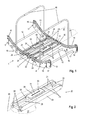
- the rocker 10 forms the frame of the training device 1 and is in Fig. 3 shown for clarity without guide rails 20.
- the rocker 10 comprises two rocker skids 11, which rest on a bottom surface, not shown.
- the symmetrically curved rocker skids 11 have a curved at their free ends upwards, convex shape and are comparable with skids of a rocking horse.
- the two rocker skids 11 are spaced parallel to each other and connected by means of a plurality of transverse struts 12 stable and distortion-free.
- the cross struts 12 are here made of metal, for example, and bolted to the rocker skids 11.
- the cross struts 12 can be made, for example, from stainless steel or from an aluminum alloy.
- the rocker skids 11 are made for example of hardwood or plastic and have on their underside or bearing surface example of a non-slip rubber coating. At the tops of the rocker skids 11 each curved rocker rails 13 are fixed, wherein the rocker rails 13 at least partially also have a convex curvature.
- the rocker rails 13 are made, for example, of metal or of a plastic, for example polyamide, and serve for receiving and supporting guide rail rollers 22, which are each fastened to guide rails 20 on the front side.
- guide rail rollers 22 which are movably mounted in the rocker rails 13, two guide rails 20 each substantially in the lateral direction 29 and transverse to the longitudinal direction 26 of the guide rails 20 between the Rocker skids 11 are reciprocated. This lateral movement direction 29 is in Fig. 1 sketched by double arrows 29.
- securing brackets 14 are fastened above the rocker rails 13 at a suitable distance, which essentially corresponds to a diameter of the guide rail rollers 20.
- the circlips 14 are attached at their ends to the rocker skids 11 and can also be dismantled for maintenance purposes.
- center of the rocker rails 13 is in each case a center stop 15, which is made here for example of hard rubber or a sheathed plastic.
- the center stopper 15 prevents the two movably mounted guide rails 20 are each movable in the lateral direction 29 via a center position of the rocker rails 13 and rocker runners 11 and is used in particular for training beginners as an aid in learning to work with the training device according to the invention 1.
- the center stopper 15th on the two rocker rails 13 are removable, whereby the two guide rails 20 are also in each case on the center position of the rocker skids 11 going along a total rocker rail length in the lateral direction 29 back and forth movable.
- each edge stopper 16 are provided which have a damping effect for the guide rails 20 and are also made for example of hard rubber.
- the free runner ends 17 of the rocker skids 11 are during training - comparable to the runners of a rocking horse - in the direction of arrow 19 up and down movable.
- This up and down movement in the direction of arrow 19 is substantially perpendicular to a guide rail plane 27, which is spanned by the centrally located guide rails 20 and the longitudinal axis directions 26 of the tread surface rails 21.
- a substantially vertical distance 18 between the underside of the rocker blade 11 and the rocker rail 13 increases toward the free rocker runner end 17 towards.
- each movably mounted foot plates 30 are how the pictures Fig. 2 and Fig. 5 can be seen, for example, rectangular plates, which serve as treads 31.
- each footplate rollers 32 which are guided by the tread rails 21 of the guide rails 20 and substantially in the longitudinal direction 26 of the guide rails 20 are movably supported in the direction of arrow 39 back and forth.
- Rail covers 23 on the tops of the tread rails 21 prevent the footplate rollers 32 of the footplates 30 from jumping out of the tread rails 21 during exercise and further provide safety during exercise.
- the rail covers 23, side covers 24 and center covers 25 are removable, whereby any required replacement of the foot plate rollers 32 is particularly easy. All covers of the stable frame of the guide rails 20 are here made of a robust, impact-resistant hard plastic.
- Fig. 2 concerns a combination of the two illustrations 4 and FIG. 5 each individually illustrated assemblies guide rail 20 and base plate 30, wherein in Fig. 2 the illustrated base plate 30 is already mounted in the guide rail 20 in the arrow direction 39 and in the longitudinal direction 26 movably mounted forward and backward.
- the illustrated base plate 30 is already mounted in the guide rail 20 in the arrow direction 39 and in the longitudinal direction 26 movably mounted forward and backward.
- two guide rail rollers 22 are arranged on each guide rail 20 and are provided for receiving in the guide rails of the rocker rails 13. Dashed line is also the guide rail plane 27, which is spanned by the two tread rails 31.
- Fig. 1 illustrated exercise device 1 possible to put the feet on the two treads 31 while pushing the foot plates 30 within the guide rails 20 simultaneously or alternately in the direction of arrow 39 each forward and / or backward.
- the tread surfaces 31 can be moved laterally by lateral movement of the guide rails 20 in the direction of arrow 29 back and forth.
- the treads 31 are here equipped with a particularly non-slip rubber coating.
- the entire training device 1 with its rocker skids 11 at the free ends in the direction of arrow 19 rocking move up or down.
- the rocking movement of the training device 1 in the direction of arrow 19 by the user by holding and swinging the two handrails 40 are controlled.
- the swinging of the rocker is already caused by minimal shear point shift of the user. While exercising can be done by the exercising person Clinging to the handrails of the rocking motion, which is caused by the rocker, are also actively counteracted. Thus, it is possible to achieve movement of the exerciser 1 in all spatial directions 19, 29, 39 by muscle action of the arm and leg muscles as well as by displacement of the upper body and thus to train in addition to the coordination and the balance particularly efficient.
- handrails 40 are attached to the rocker skids 11 by means of handrail brackets 41 so that a user can hold on the training device 1 during training.
- the handrails 40 which are here adjustable in height and equipped with soft and non-slip grip pads can also be disassembled.
- the handrails 40 can here also be adjusted in their inclination, whereby both substantially horizontal and obliquely inclined handrails 40 are adjustable. Since the handrails 40 provide the user with a stable grip during training, the user can perform any desired variety of movements with the training device 1.
- an additional tread storage 33 of the treads 31 opposite the foot plates 30 may be provided, which in Fig. 5 however not explicitly shown.
- the tread surfaces 31 are additionally mounted by means of a tread surface 33 relative to the base plates 30.
- a tread surface bearings 33 for example, rotatable and / or tiltable bearing elements are conceivable, whereby the treads 31 rotate relative to the guided in the tread surface rails 21 foot plates 30 and / or tilt sideways and thereby results for coordination training with the training device 1 an additional level of difficulty.
- resistance adjustment devices 50 are indicated. By means of these adjustment devices 50 it is possible, for example, to vary a rolling resistance of the guide rail rollers 22 and / or base plate rollers 32 and / or the tread surface rails 21. Depending on the design of the resistance adjustment devices 50, it is thus possible with a training device 1 according to the invention to use this in addition to a coordination and balance training in addition to a strength and endurance training.
- resistance adjustment devices 50 on the guide rail rollers 22 and / or foot plate rollers 32 can act on a rolling resistance of the respective roller bearings, whereby a bearing resistance of the guide rail rollers 22 and / or the disorderplattenrollen 32 can be adjusted.
- resistance adjustment devices 50 for example in the area of the tread surface rails 21.
- a variation of the roll resistance for example, by the attachment of anti-slip deposits made of different materials within the tread rails 21 can be achieved.
- the roll resistance of the footplate rollers 32 is increased, thus increasing the user's resistance to be overcome.
- FIG. 6 shows a rail cover 23, as it serves to cover the tread rails 21 and, for example, in Fig. 2 is shown in built-in position.
- the here in Fig. 6 illustrated rail cover 23 differs, however, by a horrsverstell Nur 50, which is fixed here as a brake bar 51 on the underside of the rail cover 23, from the covers described above.
- the brake bar 51 which mechanically acts in the installed position on the footplate rollers 32 below, the movement 39 of the contemplatplattenrollen 32 and thus the base plates 30 is braked.
- the brake bar 51 is for example made of an abrasion-resistant Elastomer produced.
- the distance between the rail cover 23 and the tread rail 21 can be varied and thus the mechanical resistance of the resistance adjustment 50 are adjusted.
- As a variable height adjustment for example, interchangeable locking pins or threaded rods are conceivable.
- Fig. 7 is one too Fig. 6 comparable safety bracket 14 is shown, which is also equipped on its underside with a Wegverstell Nur 50, which is performed by a brake bar 51 made of rubber.
- the brake bar 51 also acts mechanically on the underlying, movably mounted guide rail rollers 22, whereby the movement 29 of the guide rails 20 along the rocker rails 13 is braked.
- height adjustment 53 such as interchangeable locking pin, the height distance between the securing bracket 14 and the rocker rail 13 can be adjusted.
- a mechanically acting resistance of the resistance adjustment device 50 can also be varied in the area of the rocker rails 13.
Abstract
Description
Die Erfindung betrifft ein Trainingsgerät mit den Merkmalen des Oberbegriffs von Anspruch 1.The invention relates to a training device having the features of the preamble of
Aus dem Stand der Technik sind unterschiedliche Ausführungsformen von Trainingsgeräten zur motorischen Koordination sämtlicher Gliedmaßen eines Benutzers bekannt, bei deren Benutzung gemeinsam mit dem motorischen Training auch ein Gleichgewichtstraining erfolgt.Different embodiments of training devices for the motor coordination of all limbs of a user are known from the prior art, in their use, together with the motor training and balance training.
Beispielsweise ist aus dem Dokument
Es ist somit Aufgabe der vorliegenden Erfindung ein Trainingsgerät zu schaffen, welches die geschilderten Nachteile des Standes der Technik vermeidet, möglichst einfach in seiner Herstellung sowie Bedienung sowie wartungsarm ist sowie ein universelles Bewegungs- und Koordinationstraining sowohl für die Arme als auch die Beine eines Benutzers ermöglicht. Diese Aufgabe wird bei einem Trainingsgerät gemäß dem Oberbegriff des Anspruchs 1 mit den Merkmalen des kennzeichnenden Teiles des Anspruchs 1 gelöst. Die Unteransprüche betreffen besonders vorteilhafte Ausgestaltungen der Erfindung.It is therefore an object of the present invention to provide a training device which avoids the disadvantages of the prior art, as simple as possible in its manufacture and operation and low maintenance and allows universal movement and coordination training for both the arms and the legs of a user , This object is achieved in a training device according to the preamble of
Bei einem erfindungsgemäßen Trainingsgerät zum Koordinations- und/oder Gleichgewichtstraining, umfassend zwei Fußplatten, welche jeweils unabhängig voneinander entlang von Führungsschienen im Wesentlichen in Längsrichtung der Führungsschienen beweglich gelagert sind, wobei die Führungsschienen jeweils entlang von Wippenschienen im Wesentlichen quer zur Längsrichtung der Führungsschienen beweglich gelagert sind, sind die Wippenschienen an einer Wippe umfassend gewölbte Wippenkufen befestigt, wobei die freien Enden der Wippenkufen im Wesentlichen senkrecht auf eine Führungsschienenebene gemeinsam beweglich sind.In a training device according to the invention for coordination and / or balance training, comprising two foot plates, which are each mounted independently along guide rails substantially in the longitudinal direction of the guide rails, wherein the guide rails are mounted in each case along rocker rails substantially transversely to the longitudinal direction of the guide rails movable , The rocker rails are mounted on a rocker fully curved rocker skids, the free ends of the rocker skids are movable together substantially perpendicular to a guide rail plane.
Mit einem erfindungsgemäßen Trainingsgerät können vorteilhaft sowohl die Koordination, als auch das Gleichgewicht trainiert werden. Durch die Konstruktion des Trainingsgeräts können Bewegungen in sämtlichen Raumrichtungen durchgeführt werden. Ein Benutzer stellt sich dazu während des Trainings auf die beiden Fußplatten, welche innerhalb der beiden Führungsschienen unabhängig voneinander im Wesentlichen entlang deren Längsrichtung vorwärts und rückwärts beweglich gelagert sind. Zusätzlich können die beiden Führungsschienen ebenfalls voneinander unabhängig im Wesentlichen quer zur Längsrichtung der Führungsschienen seitwärts hin und her bewegt werden. Dazu sind die beiden Führungsschienen in Wippenschienen entlang der Wippenkufen beweglich gelagert. Die Wippenkufen weisen an ihren Unterseiten eine Wölbung bzw. konvexe Krümmung auf. Durch Gewichtsverlagerung des auf dem Trainingsgeräts federnd stehenden Benutzers werden die beiden Führungsschienen im Wesentlichen quer zu deren Längsrichtung in einer Seitwärtsbewegung zu den freien Wippenkufenenden an eine der beiden Wippenkufenseiten hin bewegt. Bei Erreichen eines äußeren Wippenschienenabschnitts bzw. bei Erreichen eines Randstoppers am äußeren Ende der Wippenschiene wird die Seitwärtsbewegung der beiden Führungsschienen gestoppt und die Führungsschienen können in die entgegengesetzte Seitwärtsrichtung etwa quer zu deren Längsrichtung wieder zurück bewegt werden. Somit werden die Führungsschienen vom darauf stehenden Benutzer jeweils aus der Mittellage alternierend in die beiden Randlagen ausgelenkt. Durch die Gewichtsverlagerung des darauf stehenden Benutzers bewegt sich das Trainingsgerät an seinen freien Wippenkufenenden somit wippend auf und ab.With a training device according to the invention advantageously both the coordination and the balance can be trained. Due to the construction of the training device movements in all spatial directions can be performed. A user turns to this during training on the two foot plates, which are independently supported within the two guide rails substantially along the longitudinal direction forward and backward. In addition, the two guide rails can also be moved laterally back and forth independently of one another, essentially transversely to the longitudinal direction of the guide rails. For this purpose, the two guide rails are movably mounted in rocker rails along the rocker runners. The rocker skids have a curvature or convex curvature on their undersides. By shifting the weight of the user standing on the training device, the two guide rails are moved substantially transversely to their longitudinal direction in a sideward movement towards the free rocker runner ends on one of the two sides of the rocker platform. Upon reaching an outer rocker rail section or when reaching an edge stopper at the outer end of the rocker rail, the sideways movement of the two guide rails is stopped and the guide rails can be moved back in the opposite sideways direction approximately transversely to the longitudinal direction. Thus, the guide rails are deflected by the user standing thereon from the center position alternately into the two peripheral positions. By shifting the weight of the user standing on it, the training device moves on its free rocker runners thus rocking up and down.
Die Füße des Benutzers können während des Trainings vorteilhaft innerhalb der Führungsschienenebenen jeweils unabhängig voneinander seitwärts sowie vorwärts und/oder rückwärts bewegt werden. Somit können von den Füßen des Benutzers beliebige kreis- oder schlangenförmige Bewegungsabläufe durchgeführt werden. Zusätzlich werden diese Bewegungen von der wippenden Auf- und Abbewegung des Trainingsgeräts überlagert. Somit ist das erfindungsgemäße Trainingsgerät bestens zum Koordinations- und/oder Gleichgewichtstraining geeignet.The user's feet may advantageously move laterally and forward and / or independently within the guide rail planes during exercise, respectively be moved backwards. Thus, any circular or serpentine movements can be performed by the user's feet. In addition, these movements are superimposed by the rocking up and down movement of the training device. Thus, the training device according to the invention is ideally suited for coordination and / or balance training.
Vorteilhaft weisen bei einem erfindungsgemäßen Trainingsgerät die Wippenschienen jeweils einen zumindest abschnittsweise konvex gekrümmten Schienenverlauf auf. Durch die zumindest abschnittsweise konvex gekrümmten Wippenschienen wird während des Trainings die Wippbewegung des Trainingsgeräts, welche der darauf stehende Benutzer erzielt, vorteilhaft verstärkt.Advantageously, in a training device according to the invention, the rocker rails each have an at least partially convex curved rail track. Due to the at least partially convexly curved rocker rails the rocking movement of the training device, which achieves the user standing thereon, advantageously reinforced during training.
In einer besonders vorteilhaften Ausführung der Erfindung weist bei einem Trainingsgerät jede Wippenschiene jeweils einen mittleren Wippenschienenabschnitt auf, welcher im Wesentlichen flach ist oder einen Kurvenverlauf mit einem großen Krümmungsradius hat, wobei an den mittleren Wippenschienenabschnitt anschließend zwei äußere Wippenschienenabschnitte jeweils einen kleineren Krümmungsradius aufweisen. In dieser Ausführung wird die Seitwärtsbewegung der Führungsschienen entlang der Wippenschienen innerhalb der äußeren Wippenschienenabschnitte, welche einen kleineren Krümmungsradius aufweisen und somit stärker konvex gekrümmt sind, vorteilhaft nach außen abgebremst. Somit wird die Seitwärtsbewegung des auf den Fußplatten stehenden Benutzers jeweils zu den beiden äußeren Rändern der Wippenkufen hin gebremst und eine Gefahr des unbeabsichtigten Herabfallens des Benutzers während des Trainings reduziert.In a particularly advantageous embodiment of the invention, each rocker rail in a training device each have a central rocker rail section which is substantially flat or has a curve with a large radius of curvature, with two outer rocker rail sections each having a smaller radius of curvature on the central rocker rail section. In this embodiment, the sideways movement of the guide rails along the rocker rails within the outer rocker rail sections, which have a smaller radius of curvature and are therefore more convexly curved, are advantageously braked outwards. Thus, the sideways movement of the user standing on the footplates is braked toward the two outer edges of the rocker skids and a risk of unintentional falling of the user during training is reduced.
Zweckmäßig weisen bei einem erfindungsgemäßen Trainingsgerät ausgehend vom mittleren Wippenschienenabschnitt die äußeren Wippenschienenabschnitte zu den freien Wippenkufenenden hin jeweils einen Kurvenverlauf mit zunehmender Krümmung auf. Der Kurvenverlauf der äußeren Wippenschienenabschnitte beschreibt beispielsweise einen hyperbolischen oder parabolischen Verlauf mit nach außen zu den freien Wippenkufenenden hin zunehmender konvexer Krümmung.Expediently, in a training device according to the invention, starting from the central rocker rail section, the outer rocker rail sections each have a curve course with increasing curvature towards the free rocker runner ends. The curve of the outer rocker rail sections describes, for example, a hyperbolic or parabolic curve with outwardly towards the free rocker runner ends towards increasing convex curvature.
Vorteilhaft ist in einer weiteren erfindungsgemäßen Ausführung bei einem Trainingsgerät die Krümmung des Kurvenverlaufs der äußeren Wippenschienenabschnitte verstellbar. Vorteilhaft können in dieser Ausführungsvariante die äußeren Wippenschienenabschnitte in ihrem Kurvenverlauf so verstellt werden, dass sich deren Krümmung ändert. Durch manuelle Einstellung der Krümmung bzw. des Kurvenverlaufs lassen sich unterschiedliche Schwierigkeitsgrade für das Training mit dem erfindungsgemäßen Trainingsgerät variieren. Beispielsweise sind dazu in einer ersten Ausführungsvariante Einlagen vorgesehen, die zwischen der Wippenkufe und dem jeweiligen äußeren Wippenschienenabschnitt eingesteckt bzw. austauschbar befestigt werden, wodurch die freien Wippenschienenenden stärker konvex nach oben gekrümmt werden. Vorteilhaft sind die Wippenschienen dazu aus einem biegbaren Material hergestellt oder es sind dazu die Wippenschienen an den Wippenkufen besonders einfach auswechselbar befestigt. Als biegbares Material für die Wippenschienen kann beispielsweise Kunststoff eingesetzt werden. Erforderlichenfalls müssen bei Austausch der Wippenschienen auch allfällig vorgesehene Sicherungsbügel ausgetauscht werden, welche Sicherungsbügel ein Herausfallen der Führungsschienen aus den Wippenschienen während des Trainings verhindern. Durch den Austausch entsprechend passgenauer Sicherungsbügel wird gewährleistet, dass die Krümmung der ausgetauschten Wippenschienen mit der Krümmung der Sicherungsbügel wiederum korrespondiert und ein Herausfallen der Führungsschienen während des Trainings somit auch bei verändertem Krümmungsverlauf zuverlässig vermieden wird.Advantageously, in a further embodiment of the invention in a training device, the curvature of the curve of the outer rocker rail sections adjustable. Advantageously, in this embodiment, the outer rocker rail sections are adjusted in their curve so that their curvature changes. By manually adjusting the curvature or the curve, different levels of difficulty for training with the exercise device according to the invention can be varied. For example, in a first embodiment, inserts are provided which are inserted or interchangeable between the rocker runner and the respective outer rocker rail section, whereby the free rocker rail ends are curved more convexly upward. Advantageously, the rocker rails are made of a bendable material or it is the rocker rails attached to the rocker runners particularly easy replaceable. As a bendable material for the rocker rails, for example, plastic can be used. If necessary, when replacing the rocker rails and any provided circlips must be replaced, which circlip prevent falling out of the guide rails from the rocker rails during training. By exchanging according to accurately fitting circlips ensures that the curvature of the replaced rocker rails with the curvature of the circlip again corresponds and falling out of the guide rails during training is thus reliably avoided even with a change in curvature.
In einer weiteren Ausführungsvariante ist es beispielsweise denkbar, die Wippenschienen aus einem besonders robusten Werkstoff, beispielsweise aus Metall, zu fertigen und mit einem Verstellmechanismus so an den Wippenkufen zu befestigen, dass die äußeren Wippenschienenabschnitte jeweils in ihrer Krümmung gegenüber dem mittleren Wippenschienenabschnitt verstellbar angeordnet sind.In a further embodiment variant, it is conceivable, for example, to manufacture the rocker rails made of a particularly robust material, for example of metal, and to fasten them with an adjusting mechanism to the rocker runners such that the outer rocker rail sections are each adjustably arranged in their curvature relative to the central rocker rail section.
In einer bevorzugten Ausführung der Erfindung nimmt bei einem Trainingsgerät entlang des äußeren Wippenschienenabschnitts ein im Wesentlichen senkrechter Abstand zwischen einer Unterseite der Wippenkufe und der Wippenschiene zum freien Wippenkufenende hin zu. Der Abstand zwischen den Unterseiten der Wippenkufen, an denen das Trainingsgerät am Boden aufliegt bzw. an denen das Trainingsgerät während des Trainings wippend abrollt, und den Wippenschienen an den Oberseiten der Wippenkufen nimmt in dieser Ausführungsform der Erfindung insbesondere entlang des äußeren Wippenschienenabschnitts zum freien Wippenkufenende hin zu. Somit weist der äußere Wippenschienenabschnitt einen kleineren Krümmungsradius auf, als dies im korrespondierenden Abschnitt der Unterseite der Wippenkufen der Fall ist. Durch den nach außen hin größer werdenden Abstand wird die Höhendifferenz bzw. Steigung, welche für die Führungsschienen beim Seitwärtsgleiten entlang der äußeren Wippenschienenabschnitte nach außen überwunden werden muss, ebenfalls größer. Durch die nach außen zunehmende Steigung wird die Seitwärtsbewegung der Führungsschienen vorteilhaft zu den Randstoppern verlangsamt.In a preferred embodiment of the invention increases in a training device along the outer rocker rail section, a substantially vertical distance between a bottom of the rocker blade and the rocker rail to the free rocker runner end towards. The distance between the undersides of the rocker runners on which the training device rests on the ground or on which the training device rocking during training, and the rocker rails on the tops of the rocker runners takes in this embodiment of the invention, in particular along the outer rocker rail section to the free rocker runner end to. Thus, the outer rocker rail portion has a smaller radius of curvature than is the case in the corresponding portion of the underside of the rocker skids. By increasing the distance to the outside, the height difference or slope, which must be overcome for the guide rails when sliding sideways along the outer rocker rail sections to the outside, also larger. By increasing outward slope, the sideways movement of the guide rails is advantageously slowed to the edge stops.
In einer besonders sicheren Variante der Erfindung ist bei einem Trainingsgerät entlang der Wippenschienen jeweils ein vorzugsweise demontierbarer Sicherungsbügel vorgesehen. Der Sicherungsbügel, welcher entlang der Wippenschienen befestigt ist, bietet den Vorteil, dass die Führungsschienen beim Training nicht unbeabsichtigt aus den Wippenschienen springen können. Somit wird eine mögliche Verletzungsgefahr beim Training mit dem erfindungsgemäßen Trainingsgerät vorteilhaft reduziert.In a particularly safe variant of the invention, in each case a preferably removable safety clip is provided in the case of a training device along the rocker rails. The securing bracket, which is fastened along the rocker rails, offers the advantage that the guide rails can not unintentionally jump out of the rocker rails during training. Thus, a possible risk of injury during training with the exercise device according to the invention is advantageously reduced.
Besonders zweckmäßig weisen bei einem erfindungsgemäßen Trainingsgerät die Führungsschienen an ihren Stirnseiten jeweils Führungsschienenrollen zur beweglichen Lagerung entlang der Wippenschienen auf. In dieser bevorzugten Ausführung sind an den Führungsschienen, welche beispielsweise eine stabile Rahmenform aufweisen, stirnseitig überstehend Führungsschienenrollen angeordnet, welche in die Wippenschienen eingelegt werden bzw. in diese eingreifen. Die Führungsschienenrollen weisen beispielsweise aus dem Stand der Technik bekannte Lagermittel, beispielsweise Kugel- oder Wälzlager zur leichtgängigen Lagerung der Führungsschienen auf. Somit können auch Benutzer mit höherem Körpergewicht leichtgängig und ohne wesentliche Kraftanstrengung mit dem Trainingsgerät ihre Koordination trainieren.Particularly expedient, in a training device according to the invention, the guide rails on each of their end faces on each guide rail rollers for movable mounting along the rocker rails. In this preferred embodiment, on the guide rails, which have, for example, a stable frame shape, frontally projecting guide rail rollers are arranged, which are inserted into the rocker rails or engage in these. The guide rail rollers have, for example, known from the prior art bearing means, such as ball or roller bearings for easy storage of the guide rails. Thus, even users with higher body weight smoothly and without significant effort with the exercise machine to train their coordination.
Vorteilhaft liegen bei einem erfindungsgemäßen Trainingsgerät die Führungsschienenrollen formschlüssig an einem Profil der Wippenschienen auf. In dieser Ausführung greifen die Führungsschienenrollen formschlüssig in die Wippenschienen ein oder liegen auf diesen formschlüssig auf. Somit wird entlang der Wippenschienen eine besonders präzise Seitwärtsbewegung im Wesentlichen quer zur Längsrichtung der Führungsschienen erzielt.Advantageously, in a training device according to the invention, the guide rail rollers form-fitting manner on a profile of the rocker rails. In this embodiment, the guide rail rollers engage positively in the rocker rails or lie on these form-fitting manner. Thus, along the rocker rails a particularly precise sideways movement is achieved substantially transversely to the longitudinal direction of the guide rails.
Zweckmäßig ist bei einem Trainingsgerät gemäß der Erfindung jede der Führungsschienen mit parallel gegenüberliegenden Trittflächenschienen zur Lagerung einer Fußplatte, vorzugsweise zur Lagerung von Fußplattenrollen einer Fußplatte, ausgestattet. Die Fußplatten werden in dieser Ausführung jeweils entlang von Trittflächenschienen, welche im Wesentlichen in Längsrichtung der Führungsschienen angeordnet sind, beweglich gelagert.Suitably, in a training device according to the invention, each of the guide rails with parallel opposing tread rails for supporting a foot plate, preferably for the storage of Fußplattenrollen a foot plate equipped. In this embodiment, the foot plates are each movably mounted along tread rails, which are arranged essentially in the longitudinal direction of the guide rails.
Von Vorteil weist bei einem erfindungsgemäßen Trainingsgerät eine Fußplatte jeweils Fußplattenrollen zur Lagerung in Trittflächenschienen auf. Die Fußplattenrollen sind beispielsweise mit an sich bekannten Lagermitteln leichtgängig gelagert.Advantageously, in a training device according to the invention, a foot plate on each Fußplattenrollen for storage in tread surface rails. The Fußplattenrollen are easily stored, for example, with known storage means.
In einer weiteren bevorzugten Ausführung der Erfindung stehen bei einem Trainingsgerät die Fußplattenrollen jeweils seitlich über die Fußplatte hervor. In dieser Ausführung werden die Fußplattenrollen besonders komfortabel in die Trittflächenschienen eingelegt und können zwischen diesen hin und her bewegt werden.In a further preferred embodiment of the invention, in a training device, the footplate rollers protrude laterally beyond the footplate. In this embodiment will be The footplate rollers are particularly conveniently placed in the tread surface rails and can be moved back and forth between them.
Zweckmäßig sind bei einem erfindungsgemäßen Trainingsgerät an den Oberseiten der Fußplatten jeweils Trittflächen aus einem vorzugsweise rutschfesten Material angeordnet, wobei die Trittflächen gegenüber den Fußplatten mit einer Trittflächenlagerung drehbar und/oder kippbar gelenkig gelagert sind. In dieser Ausführung sind die Trittflächen gegenüber einer Unterkonstruktion der Fußplatten gelenkig gelagert. Beispielsweise ist es denkbar, im Rahmen der Erfindung eine drehbare Trittflächenlagerung vorzusehen, wodurch die Trittflächen gegenüber den Fußplatten jeweils im Wesentlichen in der Führungsschienenebene drehbar gelagert sind. Ebenfalls ist es denkbar, eine kippbare bzw. klappbare Trittflächenlagerung vorzusehen, wodurch die Trittflächen gegenüber den Fußplatten beispielsweise um die Längsrichtung der Führungsschienen seitlich kippbar werden. Ebenso ist es im Rahmen der Erfindung möglich, eine Trittflächenlagerung der Trittflächen vorzusehen, welche sowohl eine drehende als auch eine seitlich kippende Bewegung der Trittflächen gegenüber der jeweiligen Fußplatte ermöglicht. In diesen Ausführungsvarianten ist das Koordinations- und Gleichgewichtstraining mit dem Trainingsgerät besonders anspruchsvoll und daher besonders für geübte Benutzer zu empfehlen.Appropriately, in a training device according to the invention on the tops of the foot plates each treads of a preferably non-slip material are arranged, wherein the treads with respect to the foot plates are rotatably and / or tiltably articulated with a tread surface storage. In this embodiment, the treads are hinged to a substructure of the foot plates. For example, it is conceivable within the scope of the invention to provide a rotatable tread surface support, whereby the tread surfaces relative to the foot plates are each mounted rotatably substantially in the guide rail plane. It is also conceivable to provide a tiltable or hinged tread surface storage, whereby the treads are tilted laterally relative to the foot plates, for example, about the longitudinal direction of the guide rails. It is also possible within the scope of the invention to provide a tread surface of the treads, which allows both a rotating and a laterally tilting movement of the tread surfaces relative to the respective base plate. In these embodiments, the coordination and balance training with the training device is particularly demanding and therefore recommended especially for experienced users.
Als Trittflächen können beispielsweise auch Materialien mit Luft- oder Geleinlagen dienen, welche zusätzlich die feine Stütz- und Gleichgewichtsmuskulatur beanspruchen. Durch die Verstellbarkeit der Luft- und Geleinlagen kann der Schwierigkeitsgrad individuell angepasst werden.As treads, for example, materials with air or gel deposits serve, which also claim the fine support and balance muscles. Due to the adjustability of the air and gel deposits, the degree of difficulty can be adjusted individually.
Zweckmäßig ist bei einem Trainingsgerät gemäß der Erfindung an der Wippe im Wesentlichen mittig zumindest einer Wippenschiene ein Mittenstopper vorzugsweise demontierbar befestigt. In dieser Ausführung wird es insbesondere einem Anfänger erleichtert, das Trainingsgerät kennenzulernen und mit dem Einstudieren von Bewegungsabläufen während des Trainings am erfindungsgemäßen Trainingsgerät zu beginnen. Durch den Mittenstopper wird sichergestellt, dass jede Führungsschiene jeweils in ihrer eigenen Hälfte der Wippenschiene verbleibt und nicht über die Mittellage hinaus in den jeweils gegenüberliegenden äußeren Wippenschienenabschnitt bewegt werden kann. Somit wird sichergestellt, dass die seitlichen Bewegungen der Führungsschienen entlang der Wippenschienen nicht so schnell und weit ausladend erfolgen können, wie dies ohne Mittenstopper der Fall ist. Ein Mittenstopper kann sowohl nur an einer Wippenkufe, oder auch an beiden Wippenkufen montiert sein und ist vorzugsweise demontierbar, um nach einer Eingewöhnungsphase das Trainingsgerät vollständig mit sämtlichen Möglichkeiten nutzen zu können.Appropriately, in a training device according to the invention on the rocker substantially centered at least one rocker rail a center stopper preferably mounted removable. In this embodiment, it is particularly easier for a beginner to get to know the training device and to start studying the movement sequences during training on the training device according to the invention. The center stopper ensures that each guide rail remains in its own half of the rocker rail and can not be moved beyond the center position into the respective outer rocker rail section lying opposite. This ensures that the lateral movements of the guide rails along the rocker rails can not take place as quickly and expansively as is the case without the center stop. A center stopper can be mounted on only one rocker runner, or on both rocker runners and is preferably removable in order to During a familiarization phase, the training device can be used completely with all possibilities.
In einer weiteren vorteilhaften Ausführung der Erfindung ist bei einem Trainingsgerät zumindest ein vorzugsweise höhenverstellbarer und/oder in seiner Neigung verstellbarer Handlauf an der Wippe vorzugsweise demontierbar befestigt. Ein Handlauf bietet die Möglichkeit, sich während des Trainings am Trainingsgerät festzuhalten und somit auch besonders den Oberkörper sowie die Armmuskulatur zu trainieren. Der Handlauf ist vorzugsweise höhenverstellbar ausgeführt, wodurch das Trainingsgerät besonders flexibel für verschiedene Benutzer mit unterschiedlicher Körpergröße einstellbar ist. Ebenso ist es im Rahmen der Erfindung möglich, zwei oder mehrere Handläufe am Trainingsgerät vorzusehen, um einen besonders sicheren Stand für den Benutzer während des Trainings zu gewährleisten. Der zumindest eine Handlauf ist vorteilhaft auch demontierbar, wodurch das Trainingsgerät mit vergleichsweise kleinen Abmessungen besonders komfortabel transportiert oder bei Nichtgebrauch gelagert werden kann. Beispielsweise sind die Handläufe dazu steckbar, schwenkbar oder klappbar an der Wippe befestigt. Vorteilhaft kann ein Handlauf nicht nur in seiner Höhe an der Wippe verstellt werden, sondern auch in seiner Neigung. Somit ist es möglich, einen oder mehrere Handläufe jeweils wahlweise im Wesentlichen waagrecht oder mit einer bestimmten Neigung an den Wippenkufen zu befestigen.In a further advantageous embodiment of the invention, at least one preferably height-adjustable and / or adjustable in its inclination handrail on the rocker is preferably removable mounted in a training device. A handrail offers the possibility to hold on to the training device during training and thus to train especially the upper body and the arm muscles. The handrail is preferably designed to be height adjustable, whereby the training device is particularly flexible for different users with different body size adjustable. It is also possible within the scope of the invention to provide two or more handrails on the training device to ensure a particularly safe stand for the user during training. The at least one handrail is advantageously also removable, so that the training device can be transported with relatively small dimensions particularly comfortable or stored when not in use. For example, the handrails are pluggable, pivoting or hinged attached to the rocker. Advantageously, a handrail can be adjusted not only in its height on the rocker, but also in its inclination. Thus, it is possible to attach one or more handrails each optionally substantially horizontally or with a certain inclination on the rocker skids.
In einer vorteilhaften Weiterbildung der Erfindung sind bei einem Trainingsgerät die Führungsschienenrollen und/oder die Fußplattenrollen mit Widerstandsverstelleinrichtungen zur einstellbaren Auswahl eines Rollenwiderstands ausgestattet. In dieser Ausführung dient das Trainingsgerät neben den zuvor beschriebenen Funktionen für ein Koordinations- und Gleichgewichtstraining weiters auch für ein Kraft- und Ausdauertraining. Die Führungsschienenrollen und/oder die Fußplattenrollen können hier mit Widerstandsverstelleinrichtungen in ihrem Rollenwiderstand verstellt werden. Dies erfolgt beispielsweise durch Verstellschrauben, welche auf den Lagerwiderstand bzw. die Lagerreibung der Rollenlager wirken. Somit kann die Beweglichkeit der Fußplatten im Wesentlichen in Längsrichtung bzw. quer zur Längsrichtung der Führungsschienen bewusst erschwert werden, wodurch der Kraftaufwand für den Benutzer, um die Fußplatten seitwärts, vorwärts und rückwärts in der Führungsschienenebene zu bewegen, variiert werden kann.In an advantageous development of the invention, in a training device, the guide rail rollers and / or the footplate rollers are equipped with resistance adjustment devices for the adjustable selection of a roller resistance. In this embodiment, the training device is used in addition to the previously described functions for a coordination and balance training also for a strength and endurance training. The guide rail rollers and / or the Fußplattenrollen can be adjusted here with resistance adjustment in their role resistance. This is done for example by adjusting screws, which act on the bearing resistance or the bearing friction of the roller bearings. Thus, the mobility of the foot plates substantially in the longitudinal or transverse to the longitudinal direction of the guide rails can be deliberately made difficult, whereby the force required by the user to move the foot plates sideways, forwards and backwards in the guide rail plane, can be varied.
In einer weiteren Ausführungsform der Erfindung ist es denkbar, beispielsweise magnetorheologisch wirkende Bremsen an den Führungsschienenrollen und/oder den Fußplattenrollen vorzusehen und solcherart mittels eines Hydrauliksystems sowie einer elektrischen Steuereinheit die Widerstandsverstelleinrichtungen zur Auswahl der Rollenwiderstände an den Rollenlagern elektrisch bzw. hydraulisch verstellen zu können.In a further embodiment of the invention, it is conceivable, for example, to provide magnetorheologically acting brakes on the guide rail rollers and / or the footplate rollers and thus by means of a hydraulic system and a electrical control unit to adjust the resistance adjustment for selecting the roller resistances on the roller bearings electrically or hydraulically.
In einer weiteren zweckmäßigen Weiterbildung der Erfindung sind bei einem Trainingsgerät die Wippenschienen und/oder die Trittflächenschienen mit Widerstandsverstelleinrichtungen zur einstellbaren Auswahl eines Rollenwiderstands ausgestattet. Auch diese Ausführung dient insbesondere für ein zusätzliches Kraft- und Ausdauertraining mit dem Trainingsgerät. Hier wird der Rollenwiderstand der Führungsschienenrollen und/oder der Fußplattenrollen beispielsweise durch elastische, weiche oder gleithemmende Einlagen oder Auflagen, welche auf die Wippenschienen und/oder die Trittflächenschienen aufgebracht oder in diese eingelegt werden, bewusst erhöht. Diese Einlagen oder Auflagen können bei Bedarf wieder entnommen werden.In a further expedient development of the invention, the rocker rails and / or the foot surface rails are equipped with resistance adjustment devices for adjustable selection of a roll resistance in a training device. This version is also used in particular for an additional strength and endurance training with the training device. Here, the role resistance of the guide rail rollers and / or the Fußplattenrollen is deliberately increased, for example, by elastic, soft or anti-sliding deposits or constraints, which are applied to the rocker rails and / or the tread rails or inserted into this. These deposits or pads can be removed if necessary.
Weiters ist es im Rahmen der Erfindung möglich, Abdeckungen bzw. Sicherungsbügel an den Wippenschienen und/oder den Trittflächenschienen mit Widerstandsverstelleinrichtungen auszurüsten. Beispielsweise können diese Abdeckungen und Sicherungsbügel an ihren Unterseiten mit gleithemmenden Materialien versehen sein, welche mechanisch auf die Führungsschienenrollen bzw. die Fußplattenrollen einwirken und eine zusätzliche, vorzugsweise verstellbare Widerstandskraft für die Bewegung der Führungsschienen bzw. der Fußplatten bewirken.Furthermore, it is within the scope of the invention possible to equip covers or circlips on the rocker rails and / or the tread surface rails with Widerstandsverstelleinrichtungen. For example, these covers and circlips may be provided on their underside with anti-sliding materials, which act mechanically on the guide rail rollers or Fußplattenrollen and cause an additional, preferably adjustable resistance to movement of the guide rails or foot plates.
Ebenso ist es im Rahmen der Erfindung denkbar, beispielsweise Seilzüge oder Dehnungsfedern als Widerstandsverstellungseinrichtungen einzusetzen, welche beispielhaft an den Fußplatten bzw. an den Führungsschienen oder an den freien Wippenkufenenden befestigt sind, um den Kraftaufwand für eine Bewegung entlang der Wippenschienen und/oder die Trittflächenschienen variieren zu können.It is also conceivable within the scope of the invention, for example, to use cable pulls or expansion springs as resistance adjustment devices, which are fastened by way of example to the foot plates or to the guide rails or to the free rocker runner ends in order to vary the force required for movement along the rocker rails and / or the tread surface rails to be able to.
Weiter können im Rahmen der Erfindung diverse Anbauten oder Umlenkungen beispielsweise für Seilzüge für ein Krafttraining an geeigneten Stellen des Trainingsgeräts, insbesondere an den Wippenkufen, befestigt werden.Further, in the invention various attachments or deflections, for example, for cables for a strength training at appropriate points of the training device, in particular on the rocker skids, are attached.
Weitere Einzelheiten, Merkmale und Vorteile der Erfindung ergeben sich aus der nachfolgenden Erläuterung eines in den Zeichnungen schematisch dargestellten Ausführungsbeispiels.Further details, features and advantages of the invention will become apparent from the following description of an embodiment schematically illustrated in the drawings.
In den Zeichnungen zeigen jeweils in isometrischen Schrägansichten:
-
Fig. 1 eine Ausführung eines erfindungsgemäßen Trainingsgeräts in einer Vorderansicht; -
Fig. 2 eine Führungsschiene samt einer darin beweglich gelagerten Fußplatte als Detail des inFig. 1 dargestellten Trainingsgeräts; -
Fig. 3 das inFig. 1 dargestellte Trainingsgerät mit demontierten Führungsschienen; -
Fig. 4 eine Führungsschiene ohne Fußplatte als Detail eines erfindungsgemäßen Trainingsgeräts; -
Fig. 5 eine Fußplatte als Detail eines erfindungsgemäßen Trainingsgeräts; -
Fig. 6 eine Schienenabdeckung gemäß einer erfindungsgemäßen Ausführungsvariante in einer Ansicht von unten; -
Fig. 7 einen Sicherungsbügel gemäß einer erfindungsgemäßen Ausführungsvariante in einer Draufsicht schräg von oben.
-
Fig. 1 an embodiment of a training device according to the invention in a front view; -
Fig. 2 a guide rail including a movably mounted base plate as a detail of inFig. 1 illustrated exercise device; -
Fig. 3 this inFig. 1 illustrated exercise device with disassembled guide rails; -
Fig. 4 a guide rail without foot plate as a detail of a training device according to the invention; -
Fig. 5 a foot plate as a detail of a training device according to the invention; -
Fig. 6 a rail cover according to an embodiment of the invention in a view from below; -
Fig. 7 a safety bracket according to an embodiment of the invention in a plan view obliquely from above.
In
Die Wippe 10 bildet den Rahmen des Trainingsgeräts 1 und ist in
Um zu verhindern, dass die Führungsschienenrollen 22 der Führungsschienen 20 während des Trainings unbeabsichtigt aus den Führungen der Wippenschienen 13 springen können, sind zusätzlich jeweils Sicherungsbügel 14 in einem geeigneten Abstand, welcher im Wesentlichen einem Durchmesser der Führungsschienenrollen 20 entspricht, oberhalb der Wippenschienen 13 befestigt. Die Sicherungsbügel 14 sind an ihren Enden an den Wippenkufen 11 befestigt und können für Wartungszwecke auch demontiert werden.In order to prevent the
Wie in
Die freien Kufenenden 17 der Wippenkufen 11 sind während des Trainings - vergleichbar mit den Kufen eines Schaukelpferds - in Pfeilrichtung 19 nach oben und unten bewegbar. Diese Auf- und Abbewegung in Pfeilrichtung 19 erfolgt im Wesentlichen senkrecht auf eine Führungsschienenebene 27, die von den in Mittenlage befindlichen Führungsschienen 20 bzw. den Längsachsenrichtungen 26 der Trittflächenschienen 21 aufgespannt wird. Ein im wesentlichen senkrechter Abstand 18 zwischen der Unterseite der Wippenkufe 11 und der Wippenschiene 13 nimmt zum freien Wippenkufenende 17 hin zu.The free runner ends 17 of the rocker skids 11 are during training - comparable to the runners of a rocking horse - in the direction of
Innerhalb eines stabilen Rahmens der Führungsschienen 20, welche wie zuvor bereits erwähnt im Wesentlichen in Pfeilrichtung 29 seitlich bzw. quer zur Längsachsenrichtung 26 entlang der Wippenschienen 13 hin und her beweglich gelagert sind, befinden sich jeweils beweglich gelagerte Fußplatten 30. Die Fußplatten 30 sind, wie den Abbildungen
Somit ist es mit dem in
Wie in
Weiters kann eine zusätzliche Trittflächenlagerung 33 der Trittflächen 31 gegenüber den Fußplatten 30 vorgesehen sein, die in
Wie in
In den Abbildungen
Beispielsweise können Widerstandsverstellungseinrichtungen 50 an den Führungsschienenrollen 22 und/oder Fußplattenrollen 32 auf einen Rollwiderstand der jeweiligen Rollenlager einwirken, wodurch ein Lagerwiderstand der Führungsschienenrollen 22 und/oder der Fußplattenrollen 32 verstellt werden kann. Weiters ist es im Rahmen der Erfindung denkbar, Widerstandsverstellungseinrichtungen 50 beispielsweise im Bereich der Trittflächenschienen 21 vorzusehen. Dazu kann eine Variation des Rollenwiderstands beispielsweise durch das Anbringen von gleithemmenden Einlagen aus unterschiedlichen Materialien innerhalb der Trittflächenschienen 21 erzielt werden. Beispielsweise wird durch Einkleben von gleithemmenden Einlagestreifen aus Gummi entlang der Trittflächenschienen 21 der Rollenwiderstand der Fußplattenrollen 32 erhöht und somit die zu überwindende Widerstandskraft für den Benutzer erhöht.For example,
Eine weitere erfindungsgemäße Ausführungsvariante ist in den Abbildungen
In
Ebenso ist es im Rahmen der Erfindung denkbar, dass durch Anbringen von Feder-, Seil- oder Gummizügen an Teilen der Wippe 10 und/oder der Führungsschienen 20 und/oder der Fußplatten 10 die zu überwindende Widerstandskraft zum Betätigen des Trainingsgeräts 1 erhöht werden kann. Diese erfindungsgemäßen Ausführungsvarianten sind in den Abbildungen nicht explizit dargestellt.It is also conceivable within the scope of the invention that by attaching spring, rope or rubber bands to parts of the
- 11
- Trainingsgerätexerciser
- 1010
- Wippeseesaw
- 1111
- WippenkufeWippenkufe
- 1212
- Querstrebecrossmember
- 1313
- Wippenschienerocker rail
- 1414
- Sicherungsbügelsafety catch
- 1515
- Mittenstoppermiddle stopper
- 1616
- Randstopperedge stopper
- 1717
- freies Wippenkufenendefree rocker skid end
- 1818
- Abstand zwischen Wippenkufe und WippenschieneDistance between rocker runner and rocker rail
- 1919
- Bewegungsrichtung der Wippe (Doppelpfeil)Direction of movement of the rocker (double arrow)
- 2020
- Führungsschieneguide rail
- 2121
- TrittflächenschieneTread rail
- 2222
- FührungsschienenrolleGuide rail role
- 2323
- Schienenabdeckungrail cover
- 2424
- Seitenabdeckungside cover
- 2525
- Mittenabdeckungcenter cover
- 2626
- Längsrichtung der FührungsschieneLongitudinal direction of the guide rail
- 2727
- FührungsschienenebeneGuide rail plane
- 2929
- Bewegungsrichtung der Führungsschiene (Doppelpfeil)Direction of movement of the guide rail (double arrow)
- 3030
- Fußplattefootplate
- 3131
- Trittflächetread
- 3232
- FußplattenrolleFußplattenrolle
- 3333
- TrittflächenlagerungTread storage
- 3939
- Bewegungsrichtung der Trittfläche (Doppelpfeil)Movement direction of the tread (double arrow)
- 4040
- Handlaufhandrail
- 4141
- HandlaufhalterungHandrail bracket
- 4242
- mittlerer Wippenschienenabschnittmiddle rocker rail section
- 4343
- äußerer Wippenschienenabschnittouter rocker rail section
- 5050
- WiderstandsverstelleinrichtungWiderstandsverstelleinrichtung
- 5151
- Bremsleistebrake bar
- 5252
- Ausnehmungrecess
- 5353
- Höhenverstelleinrichtungheight adjustment device
Claims (16)
Applications Claiming Priority (1)
| Application Number | Priority Date | Filing Date | Title |
|---|---|---|---|
| AT504812012A AT513499B1 (en) | 2012-10-31 | 2012-10-31 | exerciser |
Publications (2)
| Publication Number | Publication Date |
|---|---|
| EP2727634A1 true EP2727634A1 (en) | 2014-05-07 |
| EP2727634B1 EP2727634B1 (en) | 2015-09-02 |
Family
ID=49230499
Family Applications (1)
| Application Number | Title | Priority Date | Filing Date |
|---|---|---|---|
| EP13184228.8A Active EP2727634B1 (en) | 2012-10-31 | 2013-09-13 | Training device |
Country Status (2)
| Country | Link |
|---|---|
| EP (1) | EP2727634B1 (en) |
| AT (1) | AT513499B1 (en) |
Cited By (7)
| Publication number | Priority date | Publication date | Assignee | Title |
|---|---|---|---|---|
| JP2017144002A (en) * | 2016-02-16 | 2017-08-24 | 株式会社コナミデジタルエンタテインメント | game machine |
| CN107213597A (en) * | 2017-07-15 | 2017-09-29 | 陇东学院 | Double sided slider bar road leg flexibility trainer |
| CN108854008A (en) * | 2018-07-19 | 2018-11-23 | 李云魁 | A kind of basket baller's defence center of gravity training institution |
| TWI648085B (en) * | 2018-01-12 | 2019-01-21 | 肯尼實業有限公司 | Multi-axis one-way power transmission system |
| CN109731310A (en) * | 2018-12-24 | 2019-05-10 | 石永秀 | A kind of land two-ski slide snow exercising machine |
| CN110115827A (en) * | 2019-05-16 | 2019-08-13 | 西脉国际医疗股份有限公司 | A kind of training aids |
| CN114569948A (en) * | 2022-03-31 | 2022-06-03 | 许昌学院 | Physical training device for exercising balance sense |
Families Citing this family (1)
| Publication number | Priority date | Publication date | Assignee | Title |
|---|---|---|---|---|
| CN108671514B (en) * | 2018-05-21 | 2020-04-28 | 牡丹江师范学院 | Auxiliary device for university student skiing training |
Citations (5)
| Publication number | Priority date | Publication date | Assignee | Title |
|---|---|---|---|---|
| DE1578640A1 (en) * | 1967-12-05 | 1971-09-16 | Heinz Regenhardt | Training device for skiing, especially for promoting mobility in parallel turns |
| US3834693A (en) | 1972-10-27 | 1974-09-10 | Raymond Lee Organization Inc | Ski instruction apparatus |
| DE10060116C1 (en) * | 2000-11-23 | 2002-06-27 | Eugen Weitzmann | Frame for simulated skiing has upper and lower rail assemblies with pivot mounting for upper frame carrying foot boards |
| US7935032B1 (en) * | 2009-12-16 | 2011-05-03 | Jackson Robert A | Exercise system |
| DE202012003092U1 (en) * | 2012-03-26 | 2012-04-26 | Oliver Seitz | training device |
Family Cites Families (1)
| Publication number | Priority date | Publication date | Assignee | Title |
|---|---|---|---|---|
| AT509940B1 (en) * | 2010-05-21 | 2015-11-15 | Dietmar Molzer | DEVICE FOR MOTORIZED DIFFERENTIATED COORDINATION FOR LEGS AND ARMS |
-
2012
- 2012-10-31 AT AT504812012A patent/AT513499B1/en active
-
2013
- 2013-09-13 EP EP13184228.8A patent/EP2727634B1/en active Active
Patent Citations (5)
| Publication number | Priority date | Publication date | Assignee | Title |
|---|---|---|---|---|
| DE1578640A1 (en) * | 1967-12-05 | 1971-09-16 | Heinz Regenhardt | Training device for skiing, especially for promoting mobility in parallel turns |
| US3834693A (en) | 1972-10-27 | 1974-09-10 | Raymond Lee Organization Inc | Ski instruction apparatus |
| DE10060116C1 (en) * | 2000-11-23 | 2002-06-27 | Eugen Weitzmann | Frame for simulated skiing has upper and lower rail assemblies with pivot mounting for upper frame carrying foot boards |
| US7935032B1 (en) * | 2009-12-16 | 2011-05-03 | Jackson Robert A | Exercise system |
| DE202012003092U1 (en) * | 2012-03-26 | 2012-04-26 | Oliver Seitz | training device |
Cited By (8)
| Publication number | Priority date | Publication date | Assignee | Title |
|---|---|---|---|---|
| JP2017144002A (en) * | 2016-02-16 | 2017-08-24 | 株式会社コナミデジタルエンタテインメント | game machine |
| CN107213597A (en) * | 2017-07-15 | 2017-09-29 | 陇东学院 | Double sided slider bar road leg flexibility trainer |
| TWI648085B (en) * | 2018-01-12 | 2019-01-21 | 肯尼實業有限公司 | Multi-axis one-way power transmission system |
| CN108854008A (en) * | 2018-07-19 | 2018-11-23 | 李云魁 | A kind of basket baller's defence center of gravity training institution |
| CN108854008B (en) * | 2018-07-19 | 2020-04-24 | 平庆路 | Basketball player defense center of gravity training mechanism |
| CN109731310A (en) * | 2018-12-24 | 2019-05-10 | 石永秀 | A kind of land two-ski slide snow exercising machine |
| CN110115827A (en) * | 2019-05-16 | 2019-08-13 | 西脉国际医疗股份有限公司 | A kind of training aids |
| CN114569948A (en) * | 2022-03-31 | 2022-06-03 | 许昌学院 | Physical training device for exercising balance sense |
Also Published As
| Publication number | Publication date |
|---|---|
| AT513499B1 (en) | 2014-05-15 |
| AT513499A4 (en) | 2014-05-15 |
| EP2727634B1 (en) | 2015-09-02 |
Similar Documents
| Publication | Publication Date | Title |
|---|---|---|
| EP2727634B1 (en) | Training device | |
| EP0383137A2 (en) | Guide rail for the treatment of the lower limbs by movement | |
| EP3551300B1 (en) | Training device for carrying out balance, meditation and/or yoga exercises | |
| DE102015117484B3 (en) | rollator | |
| EP3126017B1 (en) | Outdoor fitness apparatus | |
| EP3323475B1 (en) | Device for rudder training | |
| DE19612632C2 (en) | Training device | |
| EP1894809A2 (en) | Stair-climbing and transportation device | |
| EP1952847B1 (en) | Training device for building up diagonal movemement musculature, in particular for inside skiing technique | |
| DE102004027524B4 (en) | Multifunctional training device to strengthen the leg and back muscles | |
| EP1284152B1 (en) | Ergotherapy rocker | |
| DE202008000489U1 (en) | Tobogganing device for driving cut turns (ZipflCarver) | |
| DE202019104029U1 (en) | exerciser | |
| DE1578627A1 (en) | Exercise machine for skiing | |
| AT509940B1 (en) | DEVICE FOR MOTORIZED DIFFERENTIATED COORDINATION FOR LEGS AND ARMS | |
| EP3400988B1 (en) | Sensomotoric training and therapy device | |
| AT525754B1 (en) | Device for training the muscles of the soles of the feet | |
| DE102008016573A1 (en) | Training device for strengthening arm musculature, during e.g. nordic walking, has piston cylinder arrangement designed as manually operated type air pump and equipped with valve, which is arranged at component by bearing | |
| DE102017106640B3 (en) | treadmill | |
| DE3039462A1 (en) | Gymnastic arm movement appts. - has handles on support movable in opposition to spring or brake | |
| WO2023164732A1 (en) | Device for training the muscles of the sole of the foot | |
| DE202012003092U1 (en) | training device | |
| DE4106150A1 (en) | Underwater exercise machine - has friction free swivel body allowing water cooled exercising | |
| DE102019119713A1 (en) | Exercise device | |
| DE102004054051A1 (en) | Training device for use in e.g. alpine skiing, has body belt for training and twisting unit provided between platform and belt, where belt is twisted to holding devices in four directions by twisting unit |
Legal Events
| Date | Code | Title | Description |
|---|---|---|---|
| PUAI | Public reference made under article 153(3) epc to a published international application that has entered the european phase |
Free format text: ORIGINAL CODE: 0009012 |
|
| 17P | Request for examination filed |
Effective date: 20130913 |
|
| AK | Designated contracting states |
Kind code of ref document: A1 Designated state(s): AL AT BE BG CH CY CZ DE DK EE ES FI FR GB GR HR HU IE IS IT LI LT LU LV MC MK MT NL NO PL PT RO RS SE SI SK SM TR |
|
| AX | Request for extension of the european patent |
Extension state: BA ME |
|
| 17P | Request for examination filed |
Effective date: 20140905 |
|
| RAX | Requested extension states of the european patent have changed |
Extension state: ME Payment date: 20140905 Extension state: BA Payment date: 20140905 |
|
| RBV | Designated contracting states (corrected) |
Designated state(s): AL AT BE BG CH CY CZ DE DK EE ES FI FR GB GR HR HU IE IS IT LI LT LU LV MC MK MT NL NO PL PT RO RS SE SI SK SM TR |
|
| GRAP | Despatch of communication of intention to grant a patent |
Free format text: ORIGINAL CODE: EPIDOSNIGR1 |
|
| RIC1 | Information provided on ipc code assigned before grant |
Ipc: A63B 22/00 20060101ALN20150319BHEP Ipc: A63B 22/20 20060101ALI20150319BHEP Ipc: A63B 69/18 20060101AFI20150319BHEP |
|
| RIC1 | Information provided on ipc code assigned before grant |
Ipc: A63B 22/00 20060101ALN20150324BHEP Ipc: A63B 69/18 20060101AFI20150324BHEP Ipc: A63B 22/20 20060101ALI20150324BHEP |
|
| INTG | Intention to grant announced |
Effective date: 20150409 |
|
| GRAS | Grant fee paid |
Free format text: ORIGINAL CODE: EPIDOSNIGR3 |
|
| GRAA | (expected) grant |
Free format text: ORIGINAL CODE: 0009210 |
|
| AK | Designated contracting states |
Kind code of ref document: B1 Designated state(s): AL AT BE BG CH CY CZ DE DK EE ES FI FR GB GR HR HU IE IS IT LI LT LU LV MC MK MT NL NO PL PT RO RS SE SI SK SM TR |
|
| AX | Request for extension of the european patent |
Extension state: BA ME |
|
| REG | Reference to a national code |
Ref country code: GB Ref legal event code: FG4D Free format text: NOT ENGLISH |
|
| REG | Reference to a national code |
Ref country code: AT Ref legal event code: REF Ref document number: 746174 Country of ref document: AT Kind code of ref document: T Effective date: 20150915 Ref country code: CH Ref legal event code: EP |
|
| REG | Reference to a national code |
Ref country code: IE Ref legal event code: FG4D Free format text: LANGUAGE OF EP DOCUMENT: GERMAN |
|
| REG | Reference to a national code |
Ref country code: DE Ref legal event code: R096 Ref document number: 502013001085 Country of ref document: DE |
|
| REG | Reference to a national code |
Ref country code: CH Ref legal event code: NV Representative=s name: GACHNANG AG PATENTANWAELTE, CH Ref country code: FR Ref legal event code: PLFP Year of fee payment: 3 |
|
| PG25 | Lapsed in a contracting state [announced via postgrant information from national office to epo] |
Ref country code: LV Free format text: LAPSE BECAUSE OF FAILURE TO SUBMIT A TRANSLATION OF THE DESCRIPTION OR TO PAY THE FEE WITHIN THE PRESCRIBED TIME-LIMIT Effective date: 20150902 Ref country code: NO Free format text: LAPSE BECAUSE OF FAILURE TO SUBMIT A TRANSLATION OF THE DESCRIPTION OR TO PAY THE FEE WITHIN THE PRESCRIBED TIME-LIMIT Effective date: 20151202 Ref country code: LT Free format text: LAPSE BECAUSE OF FAILURE TO SUBMIT A TRANSLATION OF THE DESCRIPTION OR TO PAY THE FEE WITHIN THE PRESCRIBED TIME-LIMIT Effective date: 20150902 Ref country code: FI Free format text: LAPSE BECAUSE OF FAILURE TO SUBMIT A TRANSLATION OF THE DESCRIPTION OR TO PAY THE FEE WITHIN THE PRESCRIBED TIME-LIMIT Effective date: 20150902 Ref country code: GR Free format text: LAPSE BECAUSE OF FAILURE TO SUBMIT A TRANSLATION OF THE DESCRIPTION OR TO PAY THE FEE WITHIN THE PRESCRIBED TIME-LIMIT Effective date: 20151203 |
|
| REG | Reference to a national code |
Ref country code: LT Ref legal event code: MG4D Ref country code: NL Ref legal event code: MP Effective date: 20150902 |
|
| PG25 | Lapsed in a contracting state [announced via postgrant information from national office to epo] |
Ref country code: RS Free format text: LAPSE BECAUSE OF FAILURE TO SUBMIT A TRANSLATION OF THE DESCRIPTION OR TO PAY THE FEE WITHIN THE PRESCRIBED TIME-LIMIT Effective date: 20150902 Ref country code: ES Free format text: LAPSE BECAUSE OF FAILURE TO SUBMIT A TRANSLATION OF THE DESCRIPTION OR TO PAY THE FEE WITHIN THE PRESCRIBED TIME-LIMIT Effective date: 20150902 Ref country code: SE Free format text: LAPSE BECAUSE OF FAILURE TO SUBMIT A TRANSLATION OF THE DESCRIPTION OR TO PAY THE FEE WITHIN THE PRESCRIBED TIME-LIMIT Effective date: 20150902 Ref country code: PL Free format text: LAPSE BECAUSE OF FAILURE TO SUBMIT A TRANSLATION OF THE DESCRIPTION OR TO PAY THE FEE WITHIN THE PRESCRIBED TIME-LIMIT Effective date: 20150902 |
|
| PG25 | Lapsed in a contracting state [announced via postgrant information from national office to epo] |
Ref country code: NL Free format text: LAPSE BECAUSE OF FAILURE TO SUBMIT A TRANSLATION OF THE DESCRIPTION OR TO PAY THE FEE WITHIN THE PRESCRIBED TIME-LIMIT Effective date: 20150902 Ref country code: EE Free format text: LAPSE BECAUSE OF FAILURE TO SUBMIT A TRANSLATION OF THE DESCRIPTION OR TO PAY THE FEE WITHIN THE PRESCRIBED TIME-LIMIT Effective date: 20150902 Ref country code: SK Free format text: LAPSE BECAUSE OF FAILURE TO SUBMIT A TRANSLATION OF THE DESCRIPTION OR TO PAY THE FEE WITHIN THE PRESCRIBED TIME-LIMIT Effective date: 20150902 Ref country code: IS Free format text: LAPSE BECAUSE OF FAILURE TO SUBMIT A TRANSLATION OF THE DESCRIPTION OR TO PAY THE FEE WITHIN THE PRESCRIBED TIME-LIMIT Effective date: 20160102 Ref country code: IT Free format text: LAPSE BECAUSE OF FAILURE TO SUBMIT A TRANSLATION OF THE DESCRIPTION OR TO PAY THE FEE WITHIN THE PRESCRIBED TIME-LIMIT Effective date: 20150902 Ref country code: CZ Free format text: LAPSE BECAUSE OF FAILURE TO SUBMIT A TRANSLATION OF THE DESCRIPTION OR TO PAY THE FEE WITHIN THE PRESCRIBED TIME-LIMIT Effective date: 20150902 |
|
| PG25 | Lapsed in a contracting state [announced via postgrant information from national office to epo] |
Ref country code: PT Free format text: LAPSE BECAUSE OF FAILURE TO SUBMIT A TRANSLATION OF THE DESCRIPTION OR TO PAY THE FEE WITHIN THE PRESCRIBED TIME-LIMIT Effective date: 20160104 Ref country code: RO Free format text: LAPSE BECAUSE OF FAILURE TO SUBMIT A TRANSLATION OF THE DESCRIPTION OR TO PAY THE FEE WITHIN THE PRESCRIBED TIME-LIMIT Effective date: 20150902 |
|
| REG | Reference to a national code |
Ref country code: DE Ref legal event code: R097 Ref document number: 502013001085 Country of ref document: DE |
|
| REG | Reference to a national code |
Ref country code: IE Ref legal event code: MM4A |
|
| PG25 | Lapsed in a contracting state [announced via postgrant information from national office to epo] |
Ref country code: MC Free format text: LAPSE BECAUSE OF FAILURE TO SUBMIT A TRANSLATION OF THE DESCRIPTION OR TO PAY THE FEE WITHIN THE PRESCRIBED TIME-LIMIT Effective date: 20150902 |
|
| PLBE | No opposition filed within time limit |
Free format text: ORIGINAL CODE: 0009261 |
|
| STAA | Information on the status of an ep patent application or granted ep patent |
Free format text: STATUS: NO OPPOSITION FILED WITHIN TIME LIMIT |
|
| PG25 | Lapsed in a contracting state [announced via postgrant information from national office to epo] |
Ref country code: IE Free format text: LAPSE BECAUSE OF NON-PAYMENT OF DUE FEES Effective date: 20150913 |
|
| 26N | No opposition filed |
Effective date: 20160603 |
|
| PG25 | Lapsed in a contracting state [announced via postgrant information from national office to epo] |
Ref country code: SI Free format text: LAPSE BECAUSE OF FAILURE TO SUBMIT A TRANSLATION OF THE DESCRIPTION OR TO PAY THE FEE WITHIN THE PRESCRIBED TIME-LIMIT Effective date: 20150902 Ref country code: DK Free format text: LAPSE BECAUSE OF FAILURE TO SUBMIT A TRANSLATION OF THE DESCRIPTION OR TO PAY THE FEE WITHIN THE PRESCRIBED TIME-LIMIT Effective date: 20150902 |
|
| REG | Reference to a national code |
Ref country code: FR Ref legal event code: PLFP Year of fee payment: 4 |
|
| PG25 | Lapsed in a contracting state [announced via postgrant information from national office to epo] |
Ref country code: MT Free format text: LAPSE BECAUSE OF FAILURE TO SUBMIT A TRANSLATION OF THE DESCRIPTION OR TO PAY THE FEE WITHIN THE PRESCRIBED TIME-LIMIT Effective date: 20150902 |
|
| PG25 | Lapsed in a contracting state [announced via postgrant information from national office to epo] |
Ref country code: BG Free format text: LAPSE BECAUSE OF FAILURE TO SUBMIT A TRANSLATION OF THE DESCRIPTION OR TO PAY THE FEE WITHIN THE PRESCRIBED TIME-LIMIT Effective date: 20150902 Ref country code: HU Free format text: LAPSE BECAUSE OF FAILURE TO SUBMIT A TRANSLATION OF THE DESCRIPTION OR TO PAY THE FEE WITHIN THE PRESCRIBED TIME-LIMIT; INVALID AB INITIO Effective date: 20130913 |
|
| PG25 | Lapsed in a contracting state [announced via postgrant information from national office to epo] |
Ref country code: CY Free format text: LAPSE BECAUSE OF FAILURE TO SUBMIT A TRANSLATION OF THE DESCRIPTION OR TO PAY THE FEE WITHIN THE PRESCRIBED TIME-LIMIT Effective date: 20150902 |
|
| PG25 | Lapsed in a contracting state [announced via postgrant information from national office to epo] |
Ref country code: HR Free format text: LAPSE BECAUSE OF FAILURE TO SUBMIT A TRANSLATION OF THE DESCRIPTION OR TO PAY THE FEE WITHIN THE PRESCRIBED TIME-LIMIT Effective date: 20150902 Ref country code: BE Free format text: LAPSE BECAUSE OF NON-PAYMENT OF DUE FEES Effective date: 20150930 |
|
| REG | Reference to a national code |
Ref country code: FR Ref legal event code: PLFP Year of fee payment: 5 |
|
| PG25 | Lapsed in a contracting state [announced via postgrant information from national office to epo] |
Ref country code: LU Free format text: LAPSE BECAUSE OF NON-PAYMENT OF DUE FEES Effective date: 20150913 |
|
| PG25 | Lapsed in a contracting state [announced via postgrant information from national office to epo] |
Ref country code: SM Free format text: LAPSE BECAUSE OF FAILURE TO SUBMIT A TRANSLATION OF THE DESCRIPTION OR TO PAY THE FEE WITHIN THE PRESCRIBED TIME-LIMIT Effective date: 20150902 |
|
| PG25 | Lapsed in a contracting state [announced via postgrant information from national office to epo] |
Ref country code: TR Free format text: LAPSE BECAUSE OF FAILURE TO SUBMIT A TRANSLATION OF THE DESCRIPTION OR TO PAY THE FEE WITHIN THE PRESCRIBED TIME-LIMIT Effective date: 20150902 Ref country code: MK Free format text: LAPSE BECAUSE OF FAILURE TO SUBMIT A TRANSLATION OF THE DESCRIPTION OR TO PAY THE FEE WITHIN THE PRESCRIBED TIME-LIMIT Effective date: 20150902 |
|
| REG | Reference to a national code |
Ref country code: FR Ref legal event code: PLFP Year of fee payment: 6 |
|
| PG25 | Lapsed in a contracting state [announced via postgrant information from national office to epo] |
Ref country code: AL Free format text: LAPSE BECAUSE OF FAILURE TO SUBMIT A TRANSLATION OF THE DESCRIPTION OR TO PAY THE FEE WITHIN THE PRESCRIBED TIME-LIMIT Effective date: 20150902 |
|
| REG | Reference to a national code |
Ref country code: AT Ref legal event code: MM01 Ref document number: 746174 Country of ref document: AT Kind code of ref document: T Effective date: 20180913 |
|
| PG25 | Lapsed in a contracting state [announced via postgrant information from national office to epo] |
Ref country code: AT Free format text: LAPSE BECAUSE OF NON-PAYMENT OF DUE FEES Effective date: 20180913 |
|
| REG | Reference to a national code |
Ref country code: DE Ref legal event code: R082 Ref document number: 502013001085 Country of ref document: DE Representative=s name: KUHNEN & WACKER PATENT- UND RECHTSANWALTSBUERO, DE Ref country code: DE Ref legal event code: R081 Ref document number: 502013001085 Country of ref document: DE Owner name: MOLZER, DIETMAR, AT Free format text: FORMER OWNER: MOLZER, DIETMAR, GERASDORF BEI WIEN, AT Ref country code: DE Ref legal event code: R081 Ref document number: 502013001085 Country of ref document: DE Owner name: SATTLER, ERICH ERNST, AT Free format text: FORMER OWNER: MOLZER, DIETMAR, GERASDORF BEI WIEN, AT |
|
| REG | Reference to a national code |
Ref country code: DE Ref legal event code: R082 Ref document number: 502013001085 Country of ref document: DE Representative=s name: KUHNEN & WACKER PATENT- UND RECHTSANWALTSBUERO, DE Ref country code: DE Ref legal event code: R081 Ref document number: 502013001085 Country of ref document: DE Owner name: MOLZER, DIETMAR, AT Free format text: FORMER OWNER: SATTLER, ERICH ERNST, KNITTELFELD, AT Ref country code: DE Ref legal event code: R081 Ref document number: 502013001085 Country of ref document: DE Owner name: SATTLER, ERICH ERNST, AT Free format text: FORMER OWNER: SATTLER, ERICH ERNST, KNITTELFELD, AT |
|
| REG | Reference to a national code |
Ref country code: GB Ref legal event code: 732E Free format text: REGISTERED BETWEEN 20210624 AND 20210630 |
|
| REG | Reference to a national code |
Ref country code: GB Ref legal event code: 732E Free format text: REGISTERED BETWEEN 20211125 AND 20211201 |
|
| PGFP | Annual fee paid to national office [announced via postgrant information from national office to epo] |
Ref country code: FR Payment date: 20230929 Year of fee payment: 11 |
|
| PGFP | Annual fee paid to national office [announced via postgrant information from national office to epo] |
Ref country code: GB Payment date: 20231025 Year of fee payment: 11 |
|
| PGFP | Annual fee paid to national office [announced via postgrant information from national office to epo] |
Ref country code: DE Payment date: 20231018 Year of fee payment: 11 Ref country code: CH Payment date: 20231101 Year of fee payment: 11 |