EP2726223B1 - Cleaning tool and method for a polysilicon reactor - Google Patents
Cleaning tool and method for a polysilicon reactor Download PDFInfo
- Publication number
- EP2726223B1 EP2726223B1 EP12732828.4A EP12732828A EP2726223B1 EP 2726223 B1 EP2726223 B1 EP 2726223B1 EP 12732828 A EP12732828 A EP 12732828A EP 2726223 B1 EP2726223 B1 EP 2726223B1
- Authority
- EP
- European Patent Office
- Prior art keywords
- interior surface
- reactor
- reactor bell
- bell
- brush
- Prior art date
- Legal status (The legal status is an assumption and is not a legal conclusion. Google has not performed a legal analysis and makes no representation as to the accuracy of the status listed.)
- Active
Links
- 238000004140 cleaning Methods 0.000 title claims description 21
- 238000000034 method Methods 0.000 title claims description 19
- 229910021420 polycrystalline silicon Inorganic materials 0.000 title description 7
- 229920005591 polysilicon Polymers 0.000 title description 5
- 238000005229 chemical vapour deposition Methods 0.000 claims description 13
- 238000001035 drying Methods 0.000 claims description 10
- 239000007788 liquid Substances 0.000 claims description 6
- 238000011109 contamination Methods 0.000 claims description 5
- 238000007689 inspection Methods 0.000 claims description 3
- 239000007789 gas Substances 0.000 description 12
- 239000012530 fluid Substances 0.000 description 10
- XUIMIQQOPSSXEZ-UHFFFAOYSA-N Silicon Chemical compound [Si] XUIMIQQOPSSXEZ-UHFFFAOYSA-N 0.000 description 7
- 229910052710 silicon Inorganic materials 0.000 description 7
- 239000010703 silicon Substances 0.000 description 7
- 239000000356 contaminant Substances 0.000 description 6
- 238000005259 measurement Methods 0.000 description 5
- IJGRMHOSHXDMSA-UHFFFAOYSA-N Atomic nitrogen Chemical compound N#N IJGRMHOSHXDMSA-UHFFFAOYSA-N 0.000 description 4
- 239000000376 reactant Substances 0.000 description 4
- 239000000463 material Substances 0.000 description 3
- 239000007921 spray Substances 0.000 description 3
- BLRPTPMANUNPDV-UHFFFAOYSA-N Silane Chemical compound [SiH4] BLRPTPMANUNPDV-UHFFFAOYSA-N 0.000 description 2
- 230000003247 decreasing effect Effects 0.000 description 2
- 239000008367 deionised water Substances 0.000 description 2
- 239000003599 detergent Substances 0.000 description 2
- 229910052757 nitrogen Inorganic materials 0.000 description 2
- 229920001343 polytetrafluoroethylene Polymers 0.000 description 2
- 239000004810 polytetrafluoroethylene Substances 0.000 description 2
- 238000002310 reflectometry Methods 0.000 description 2
- OKTJSMMVPCPJKN-UHFFFAOYSA-N Carbon Chemical compound [C] OKTJSMMVPCPJKN-UHFFFAOYSA-N 0.000 description 1
- 229910000975 Carbon steel Inorganic materials 0.000 description 1
- 229910004721 HSiCl3 Inorganic materials 0.000 description 1
- 239000004952 Polyamide Substances 0.000 description 1
- 229910003910 SiCl4 Inorganic materials 0.000 description 1
- 239000010962 carbon steel Substances 0.000 description 1
- 150000001875 compounds Chemical class 0.000 description 1
- 238000000151 deposition Methods 0.000 description 1
- 230000008021 deposition Effects 0.000 description 1
- 239000000835 fiber Substances 0.000 description 1
- 239000011152 fibreglass Substances 0.000 description 1
- 239000011261 inert gas Substances 0.000 description 1
- 229920002647 polyamide Polymers 0.000 description 1
- -1 polytetrafluoroethylene Polymers 0.000 description 1
- 239000002243 precursor Substances 0.000 description 1
- 238000003825 pressing Methods 0.000 description 1
- 238000005201 scrubbing Methods 0.000 description 1
- 229910000077 silane Inorganic materials 0.000 description 1
- FDNAPBUWERUEDA-UHFFFAOYSA-N silicon tetrachloride Chemical compound Cl[Si](Cl)(Cl)Cl FDNAPBUWERUEDA-UHFFFAOYSA-N 0.000 description 1
- 238000005507 spraying Methods 0.000 description 1
- 239000010935 stainless steel Substances 0.000 description 1
- 229910001220 stainless steel Inorganic materials 0.000 description 1
- ZDHXKXAHOVTTAH-UHFFFAOYSA-N trichlorosilane Chemical compound Cl[SiH](Cl)Cl ZDHXKXAHOVTTAH-UHFFFAOYSA-N 0.000 description 1
- XLYOFNOQVPJJNP-UHFFFAOYSA-N water Substances O XLYOFNOQVPJJNP-UHFFFAOYSA-N 0.000 description 1
Images


Classifications
-
- B—PERFORMING OPERATIONS; TRANSPORTING
- B08—CLEANING
- B08B—CLEANING IN GENERAL; PREVENTION OF FOULING IN GENERAL
- B08B9/00—Cleaning hollow articles by methods or apparatus specially adapted thereto
- B08B9/08—Cleaning containers, e.g. tanks
- B08B9/093—Cleaning containers, e.g. tanks by the force of jets or sprays
-
- C—CHEMISTRY; METALLURGY
- C23—COATING METALLIC MATERIAL; COATING MATERIAL WITH METALLIC MATERIAL; CHEMICAL SURFACE TREATMENT; DIFFUSION TREATMENT OF METALLIC MATERIAL; COATING BY VACUUM EVAPORATION, BY SPUTTERING, BY ION IMPLANTATION OR BY CHEMICAL VAPOUR DEPOSITION, IN GENERAL; INHIBITING CORROSION OF METALLIC MATERIAL OR INCRUSTATION IN GENERAL
- C23C—COATING METALLIC MATERIAL; COATING MATERIAL WITH METALLIC MATERIAL; SURFACE TREATMENT OF METALLIC MATERIAL BY DIFFUSION INTO THE SURFACE, BY CHEMICAL CONVERSION OR SUBSTITUTION; COATING BY VACUUM EVAPORATION, BY SPUTTERING, BY ION IMPLANTATION OR BY CHEMICAL VAPOUR DEPOSITION, IN GENERAL
- C23C16/00—Chemical coating by decomposition of gaseous compounds, without leaving reaction products of surface material in the coating, i.e. chemical vapour deposition [CVD] processes
- C23C16/44—Chemical coating by decomposition of gaseous compounds, without leaving reaction products of surface material in the coating, i.e. chemical vapour deposition [CVD] processes characterised by the method of coating
- C23C16/4401—Means for minimising impurities, e.g. dust, moisture or residual gas, in the reaction chamber
- C23C16/4407—Cleaning of reactor or reactor parts by using wet or mechanical methods
-
- B—PERFORMING OPERATIONS; TRANSPORTING
- B08—CLEANING
- B08B—CLEANING IN GENERAL; PREVENTION OF FOULING IN GENERAL
- B08B9/00—Cleaning hollow articles by methods or apparatus specially adapted thereto
- B08B9/08—Cleaning containers, e.g. tanks
Definitions
- This disclosure generally relates to systems and methods for cleaning a polysilicon reactor and, more specifically, to a cleaning tool for cleaning an interior of a polysilicon reactor.
- Ultrapure polysilicon used in the electronic and solar industry is often produced through deposition from gaseous reactants via a chemical vapor deposition (CVD) process conducted within a reactor.
- CVD chemical vapor deposition
- One process used to produce ultrapure polycrystalline silicon in a CVD reactor is referred to as a Siemens process.
- Silicon rods disposed within the reactor are used as seeds to start the process.
- Gaseous silicon-containing reactants flow through the reactor and deposit silicon onto the surface of the rods.
- the gaseous reactants i.e., gaseous precursors
- the reactants are heated to temperatures above 1000°C and under these conditions decompose on the surface of the rods. Silicon is thus deposited on the rods according to the following overall reaction: 2 HSiCl 3 ⁇ Si + 2 HCl + SiCl 4 .
- the process is stopped after a layer of silicon having a predetermined thickness has been deposited on the surface of the rods.
- the rods 100 are then extracted from the CVD reactor and the silicon is harvested from the rods for further processing.
- the reactor is cleaned to remove silicon and other materials deposited on an interior surface of the reactor.
- the reactor is typically cleaned manually by a technician. The technician cleans the reactor by spraying de-ionized water against the interior surface.
- EP 2 082 814 discloses a reactor cleaning apparatus which cleans an inner wall surface of a reactor which produces polycrystalline silicon.
- One aspect is a system for cleaning an interior surface of a chemical vapor deposition reactor bell.
- the system includes a fram disposed beneath the reactor bell and connected to a flange of the reactor bell, an actuating mechanism connected to the frame, the actuating mechanism configured for vertical and rotational movement within an interior space of the reactor bell when the reactor bell is connected to the frame, at least one brush connected to the actuating mechanism, the brush configured to contact the interior surface of the reactor bell, and at least one nozzle connected to the actuating mechanism, the nozzle configured to direct a flow of liquid against the interior surface of the reactor bell.
- Another aspect is a method of cleaning an interior surface of a chemical vapor deposition reactor bell using a brush.
- the method comprises positioning the reactor bell atop a frame, operating a first actuator such that the brush engages the interior surface of the reactor bell, directing a flow of liquid from a nozzle against the interior surface of the reactor bell, and operating a second actuator to rotate the brush.
- the embodiments described herein generally relate to systems and methods for cleaning an interior surface of a chemical vapor deposition (CVD) polysilicon reactor.
- the systems are operable to rinse the interior surface with a liquid and scrub the interior surface with brushes.
- the systems may also be operable to dry the interior surface with a flow of gas.
- FIG. 1-6 An exemplary system for cleaning an interior surface of a CVD reactor is indicated generally at 100 in Figures 1-6 .
- the system 100 is positioned within a reactor bell 102 (broadly, a housing) of the CVD reactor.
- the reactor bell 102 is shown in phantom in Figures 1 and 2 .
- the system 100 may alternatively be substantially stationary and the bell may be lowered or positioned around the system by a hoist or other suitable structure.
- the system comprises a frame 104 having four legs 106 in the example embodiment.
- a flange 108 for supporting the reactor bell 102 during use is connected to the frame 104 and is positioned generally adjacent to the legs 106.
- the flange 108 has a diameter that is the same as or larger than that of a bottom flange 110 of the reactor bell 102.
- the bottom flange 110 of the reactor bell 102 is disposed on the flange 108 during use of the system 100.
- the flange 108 may have openings formed therein to accommodate mechanical fasteners used to secure the bottom flange 110 of the reactor bell 102 to the flange.
- clamps 112 attached to the frame 104 may be used to hold the bottom flange 110 of the reactor bell 102 in contact with the flange 108 of the frame 104.
- Four circumferentially spaced clamps 112 are used in the example embodiment, although different numbers or configurations of clamps can be used in other embodiments.
- the clamps 112 are shown in an unsecured state in the Figures. To fasten the bottom flange 110 of the reactor bell to the flange 108, the clamps 112 are pivoted inward.
- An articulating mechanism 120 is disposed in a central portion 122 of the system 100 and is connected to the frame. 104.
- the articulating mechanism 120 in the example embodiment has three separate actuators 124, although other embodiments may have a different number of actuators.
- Each of the actuators 124 is connected at one end to a base plate 126 that is in turn connected to the frame 104. At the other opposing end, the actuators 124 are connected to a top plate 128.
- the actuators 124 are movable in a vertical direction parallel to a vertical axis V. Each actuator 124 may be moved independently of the others.
- the articulating mechanism 120 can be rotated by about an axis parallel to the V axis by rotation of the base plate 126 and/or top plate 128.
- each pair of brushes 130 and nozzles 132 is vertically spaced apart from the other.
- the nozzles 132 are also angularly displaced relative to the brushes 130.
- an additional nozzle 134 ( Figure 4 ) is positioned above each of the nozzles 132.
- Other embodiments may use a different number and/or arrangement of nozzles and brushes.
- Each brush 130 has bristles 136 protruding from a circular-shaped head 138.
- the bristles 136 are disposed about a perimeter of the circular-shaped head 138 in the example embodiment, although in other embodiments they may be disposed in other portions of the head.
- the bristles 136 may be constructed from any suitable material, such as polyamide and fiber glass, polytetrafluoroethylene (PTFE) in combination with carbon and/or stainless steel.
- heads 138 may use heads 138 that are shaped differently (e.g., rectangular, triangular, oblong, or square).
- the brush 130 is connected to a suitable rotary actuator 140 that is operable to rotate the head 138 of the brush 130.
- the rotary actuator 140 is operable to rotate the brush 130 at a predetermined number of revolutions per minute (RPM).
- RPM revolutions per minute
- the brushes 130 rotate at approximately 200 to 300 RPMs, although other embodiments may rotate the actuator at different RPMs.
- the actuator 140 may oscillate and/or vibrate the brush 130 in addition or instead of rotating the head 138.
- the brush 130 is also connected to a suitable linear actuator 142 that is operable to laterally displace the brush 130 in a direction parallel to a horizontal axis H.
- the linear actuator 142 may also be operable to displace the brush 130 in other directions that are not parallel to the horizontal axis H.
- the linear actuator 142 is capable of exerting sufficient force on the brush 130 to press the bristles 136 of the brush 130 against an interior surface 144 ( Figure 2 ) of the reactor bell 102. This pressing of the brush 130 aids in removal of material (e.g., contaminants) disposed on the interior surface 144 of the reactor bell 102 by the bristles 136.
- one of the nozzles 132 is positioned adjacent each brush 130 in the example embodiment.
- the additional nozzle 134 is positioned vertically above the uppermost pair of brushes 130 and nozzles 132.
- the nozzles 132, 134 are each connected to the articulating mechanism 120, although in other embodiments the nozzles 132, 134 may be connected to other structures within the system 100.
- the nozzles 132 may be positioned differently such that they are not adjacent the brushes 130.
- the nozzles 132, 134 are connected to a suitable fluid supply source 146 (a portion of which is shown in Figure 2 ) capable of supplying fluid (e.g., de-ionized water, detergent, water, etc.) to the nozzles.
- the nozzles 132, 134 are used to direct (e.g., spray) fluid against the interior surface 144 of the reactor bell 102.
- This fluid may be used to rinse the interior surface 144 after the surface has been scrubbed by the bristles 136 of the head 138.
- This fluid (or another type of fluid) may also be directed (e.g., sprayed) .against the interior surface 144 while the bristles 136 of the head 138 are used to scrub the interior surface 144 of the reactor bell 102.
- a detergent fluid may be used during the scrubbing of the interior surface 144 of the reactor bell 102.
- the nozzles 132, 134 may be used to direct a flow of gas against the interior surface 144 of the reactor bell 102. This gas flow from the nozzles 132, 134 may be used to dry the interior surface 144 after the surface has been cleaned.
- a drying nozzle 150 ( Figure 6 ) is provided for directing a flow of gas against the interior surface 144 of the reactor bell 102.
- the gas is nitrogen in the example embodiment, although in other embodiments a different gas may be used (e.g., an inert gas).
- the drying nozzle 150 is connected to a portion of the articulating mechanism 120 (e.g., another actuator) that is operable to move the nozzle 150 to direct gas against different portions of the interior surface 144 of the reactor bell 102.
- the drying nozzle 150 is connected to a suitable supply of gas (not shown).
- the drying nozzle 150 is used to direct a flow of gas against a viewing window (not shown) formed in the reactor bell 102.
- the drying nozzle 150 may be used to direct a flow of gas against other portions of or the entire interior surface 144 of the reactor bell 102.
- the example embodiment includes a blower 152 positioned vertically beneath the flange 108 of the frame 104 to direct a flow of air or other suitable gas against the interior surface 144 of the reactor bell 102. This flow of air aids in drying the interior surface 144 after completion of a cleaning cycle.
- the example embodiment also includes a light 160 ( Figure 6 ) to aid in inspection of the viewing window.
- the light 160 is a fiber optic light in the example embodiment that is connected to a suitable light generator (not shown).
- the light 160 also permits inspection of the interior surface 144 of the reactor bell 102 during the cleaning cycle described in greater detail below. While one light 160 is shown in Figure 6 , multiple lights may be used and positioned throughout the system 100.
- a cleaning cycle begins when the reactor bell 102 is lowered or placed over the frame 104.
- the reactor bell 102 is then secured to the frame 104 with clamps 112 and/or suitable fasteners.
- the linear actuators 142 connected to the brushes 130 are then extended to bring the brushes into contact with the inner surface 144 of the reactor bell 102.
- Fluid is then sprayed from the nozzles 132, 134 against the interior surface 144 and the rotary actuators 140 begin to rotate the brushes 130.
- the rotation of the brushes 130 and the contact of the bristles 136 against the interior surface 144 remove deposited contaminants and/or debris from the interior surface.
- the order of these initial steps may be altered.
- the nozzles 132, 134 may spray fluid onto the interior surface 144 before the linear actuators are extended 142 and/or the brushes 130 are rotated by the rotary actuators 140.
- the articulating mechanism 120 moves the nozzles and brushes in a direction generally parallel to the vertical axis V.
- the articulating mechanism 120 also rotates the nozzles 132, 134 and brushes 130 about the vertical axis V.
- the rate of rotation and vertical movement of the articulating mechanism 120 may be adjusted in order to suitably remove debris and/or contaminants from the interior surface 144 of the reactor bell 102.
- the rate of rotation and vertical movement may be adjusted based on the amount of contamination of the interior surface 144.
- a measurement of the amount of contamination may be made by an operator or with one or more sensors. The measurement may be taken at one or more points on the interior surface 144.
- a control system then adjusts the rate of rotation and vertical movement of the articulating mechanism 120 based on this measurement. In other embodiments, an operator may adjust the rate of rotation and vertical movement of the articulating mechanism 120 based on the measurement.
- the articulating mechanism 120 may alter its rate of vertical movement and/or rotation of the brushes 130 and nozzles 132, 134 during cleaning of the interior surface 144 of the reactor bell 102.
- the rate of vertical movement and/or rotation may be decreased when cleaning portions of the interior surface 144 that have greater amounts of contaminants deposited thereon than other portions of the interior surface.
- the rates may also be decreased when cleaning portions of the interior surface 144 that have lesser amounts of contaminants deposited thereon.
- the cleaning cycle continues until the contaminants, or some portion or percentage thereof, are removed from the interior surface 144 of the reactor bell 102. In operation, another measurement may be taken to determine if the amount of contamination on the interior surface 144, or some portion or percentage thereof, have been removed from the interior surface. In other embodiments, the cleaning cycle may continue for a predetermined period of time (e.g., 30 minutes).
- the drying nozzle 150 is moved by the articulating mechanism 120 to a position adjacent the viewing window of the reactor bell 102.
- a flow of gas e.g., nitrogen
- the blower 152 may then be used to direct a flow of air against the interior surface 144 of the reactor bell 102 to dry the surface.
- the blower 152 is operable to heat the air to further aid in drying the interior surface 144.
- the clamps 112 and/or mechanical fasteners securing the reactor bell 102 to the frame 104 of the system 100 are removed.
- a hoist or other mechanism is then used to remove the reactor bell 102 from the frame 104.
- the reactor bell 102 is then either placed in service or stored for later use.
- the cleaned reactor bell will have increased reflectivity. This increased reflectivity will reduce the energy consumed in the process and thereby make the process more efficient.
Landscapes
- Chemical & Material Sciences (AREA)
- Engineering & Computer Science (AREA)
- Mechanical Engineering (AREA)
- General Chemical & Material Sciences (AREA)
- Chemical Kinetics & Catalysis (AREA)
- Materials Engineering (AREA)
- Metallurgy (AREA)
- Organic Chemistry (AREA)
- Cleaning In General (AREA)
- Physical Or Chemical Processes And Apparatus (AREA)
- Chemical Vapour Deposition (AREA)
Description
- This disclosure generally relates to systems and methods for cleaning a polysilicon reactor and, more specifically, to a cleaning tool for cleaning an interior of a polysilicon reactor.
- Ultrapure polysilicon used in the electronic and solar industry is often produced through deposition from gaseous reactants via a chemical vapor deposition (CVD) process conducted within a reactor.
- One process used to produce ultrapure polycrystalline silicon in a CVD reactor is referred to as a Siemens process. Silicon rods disposed within the reactor are used as seeds to start the process. Gaseous silicon-containing reactants flow through the reactor and deposit silicon onto the surface of the rods. The gaseous reactants (i.e., gaseous precursors) are silane-containing compounds such as halosilanes or monosilanes. The reactants are heated to temperatures above 1000°C and under these conditions decompose on the surface of the rods. Silicon is thus deposited on the rods according to the following overall reaction:
2 HSiCl3 → Si + 2 HCl + SiCl4.
- The process is stopped after a layer of silicon having a predetermined thickness has been deposited on the surface of the rods. The
rods 100 are then extracted from the CVD reactor and the silicon is harvested from the rods for further processing. - After the rods are extracted, the reactor is cleaned to remove silicon and other materials deposited on an interior surface of the reactor. In known systems, the reactor is typically cleaned manually by a technician. The technician cleans the reactor by spraying de-ionized water against the interior surface.
- This Background section is intended to introduce the reader to various aspects of art that may be related to various aspects of the present disclosure, which are described and/or claimed below. This discussion is believed to be helpful in providing the reader with background information to facilitate a better understanding of the various aspects of the present disclosure. Accordingly, it should be understood that these statements are to be read in this light, and not as admissions of prior art.
-
EP 2 082 814 discloses a reactor cleaning apparatus which cleans an inner wall surface of a reactor which produces polycrystalline silicon. - One aspect is a system for cleaning an interior surface of a chemical vapor deposition reactor bell. The system includes a fram disposed beneath the reactor bell and connected to a flange of the reactor bell, an actuating mechanism connected to the frame, the actuating mechanism configured for vertical and rotational movement within an interior space of the reactor bell when the reactor bell is connected to the frame, at least one brush connected to the actuating mechanism, the brush configured to contact the interior surface of the reactor bell, and at least one nozzle connected to the actuating mechanism, the nozzle configured to direct a flow of liquid against the interior surface of the reactor bell.
- Another aspect is a method of cleaning an interior surface of a chemical vapor deposition reactor bell using a brush is provided. The method comprises positioning the reactor bell atop a frame, operating a first actuator such that the brush engages the interior surface of the reactor bell, directing a flow of liquid from a nozzle against the interior surface of the reactor bell, and operating a second actuator to rotate the brush.
- Various refinements exist of the features noted in relation to the above-mentioned aspects. Further features may also be incorporated in the above-mentioned aspects as well. These refinements and additional features may exist individually or in any combination. For instance, various features discussed below in relation to any of the illustrated embodiments may be incorporated into any of the above-described aspects, alone or in any combination.
-
-
Figure 1 is a perspective view of a system for cleaning an interior surface of a chemical vapor deposition reactor; -
Figure 2 is a front view of the system ofFigure 1 ; -
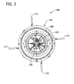
Figure 3 is a top view of the system ofFigure 1 ; -
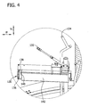
Figure 4 is an enlarged view of a portion of the system ofFigure 1 indicated by a dashed circle inFig. 1 ; -
Figure 5 is an enlarged view of a portion of the system ofFigure 1 indicated by a dashed circle inFig. 1 ; and -
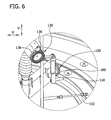
Figure 6 is an enlarged view of a portion of the system ofFigure 1 indicated by a dashed circle inFig. 1 . - Like reference symbols in the various drawings indicate like elements.
- The embodiments described herein generally relate to systems and methods for cleaning an interior surface of a chemical vapor deposition (CVD) polysilicon reactor. The systems are operable to rinse the interior surface with a liquid and scrub the interior surface with brushes. The systems may also be operable to dry the interior surface with a flow of gas.
- An exemplary system for cleaning an interior surface of a CVD reactor is indicated generally at 100 in
Figures 1-6 . During use, thesystem 100 is positioned within a reactor bell 102 (broadly, a housing) of the CVD reactor. Thereactor bell 102 is shown in phantom inFigures 1 and2 . Thesystem 100 may alternatively be substantially stationary and the bell may be lowered or positioned around the system by a hoist or other suitable structure. - The system comprises a
frame 104 having fourlegs 106 in the example embodiment. Aflange 108 for supporting thereactor bell 102 during use is connected to theframe 104 and is positioned generally adjacent to thelegs 106. Theflange 108 has a diameter that is the same as or larger than that of abottom flange 110 of thereactor bell 102. As shown inFigure 2 , thebottom flange 110 of thereactor bell 102 is disposed on theflange 108 during use of thesystem 100. Theflange 108 may have openings formed therein to accommodate mechanical fasteners used to secure thebottom flange 110 of thereactor bell 102 to the flange. Moreover,clamps 112 attached to theframe 104 may be used to hold thebottom flange 110 of thereactor bell 102 in contact with theflange 108 of theframe 104. Four circumferentially spacedclamps 112 are used in the example embodiment, although different numbers or configurations of clamps can be used in other embodiments. Moreover, theclamps 112 are shown in an unsecured state in the Figures. To fasten thebottom flange 110 of the reactor bell to theflange 108, theclamps 112 are pivoted inward. - An
articulating mechanism 120 is disposed in acentral portion 122 of thesystem 100 and is connected to the frame. 104. Thearticulating mechanism 120 in the example embodiment has threeseparate actuators 124, although other embodiments may have a different number of actuators. Each of theactuators 124 is connected at one end to abase plate 126 that is in turn connected to theframe 104. At the other opposing end, theactuators 124 are connected to atop plate 128. - Two pairs of
brushes 130 and nozzles 132 (described in greater detail below) are connected to each of theactuators 124. Theactuators 124 are movable in a vertical direction parallel to a vertical axis V. Eachactuator 124 may be moved independently of the others. The articulatingmechanism 120 can be rotated by about an axis parallel to the V axis by rotation of thebase plate 126 and/ortop plate 128. - In the example embodiment as shown in
Figures 4 and5 , each pair ofbrushes 130 andnozzles 132 is vertically spaced apart from the other. Thenozzles 132 are also angularly displaced relative to thebrushes 130. Moreover, an additional nozzle 134 (Figure 4 ) is positioned above each of thenozzles 132. There are thus ninenozzles brushes 130 in the example embodiment. Other embodiments may use a different number and/or arrangement of nozzles and brushes. - Each
brush 130, one of which is shown in detail inFigure 6 , hasbristles 136 protruding from a circular-shapedhead 138. Thebristles 136 are disposed about a perimeter of the circular-shapedhead 138 in the example embodiment, although in other embodiments they may be disposed in other portions of the head. Thebristles 136 may be constructed from any suitable material, such as polyamide and fiber glass, polytetrafluoroethylene (PTFE) in combination with carbon and/or stainless steel. Moreover, some embodiments may useheads 138 that are shaped differently (e.g., rectangular, triangular, oblong, or square). - As shown in
Figures 4 and5 , thebrush 130 is connected to a suitablerotary actuator 140 that is operable to rotate thehead 138 of thebrush 130. According to one embodiment, therotary actuator 140 is operable to rotate thebrush 130 at a predetermined number of revolutions per minute (RPM). In the example embodiment, thebrushes 130 rotate at approximately 200 to 300 RPMs, although other embodiments may rotate the actuator at different RPMs. Moreover, theactuator 140 may oscillate and/or vibrate thebrush 130 in addition or instead of rotating thehead 138. - The
brush 130 is also connected to a suitablelinear actuator 142 that is operable to laterally displace thebrush 130 in a direction parallel to a horizontal axis H. In other embodiments, thelinear actuator 142 may also be operable to displace thebrush 130 in other directions that are not parallel to the horizontal axis H. Thelinear actuator 142 is capable of exerting sufficient force on thebrush 130 to press thebristles 136 of thebrush 130 against an interior surface 144 (Figure 2 ) of thereactor bell 102. This pressing of thebrush 130 aids in removal of material (e.g., contaminants) disposed on theinterior surface 144 of thereactor bell 102 by thebristles 136. - As referenced above, one of the
nozzles 132 is positioned adjacent eachbrush 130 in the example embodiment. Theadditional nozzle 134 is positioned vertically above the uppermost pair ofbrushes 130 andnozzles 132. Thenozzles mechanism 120, although in other embodiments thenozzles system 100. In the example embodiment, there are an equal number ofnozzles 132 and brushes 130. In other embodiments, there may be more or less nozzles 132' than brushes 130. Moreover, thenozzles 132 may be positioned differently such that they are not adjacent thebrushes 130. - The
nozzles Figure 2 ) capable of supplying fluid (e.g., de-ionized water, detergent, water, etc.) to the nozzles. Thenozzles interior surface 144 of thereactor bell 102. This fluid may be used to rinse theinterior surface 144 after the surface has been scrubbed by thebristles 136 of thehead 138. This fluid (or another type of fluid) may also be directed (e.g., sprayed) .against theinterior surface 144 while thebristles 136 of thehead 138 are used to scrub theinterior surface 144 of thereactor bell 102. For example, a detergent fluid may be used during the scrubbing of theinterior surface 144 of thereactor bell 102. In some embodiments, thenozzles interior surface 144 of thereactor bell 102. This gas flow from thenozzles interior surface 144 after the surface has been cleaned. - In the example embodiment, a drying nozzle 150 (
Figure 6 ) is provided for directing a flow of gas against theinterior surface 144 of thereactor bell 102. The gas is nitrogen in the example embodiment, although in other embodiments a different gas may be used (e.g., an inert gas). The dryingnozzle 150 is connected to a portion of the articulating mechanism 120 (e.g., another actuator) that is operable to move thenozzle 150 to direct gas against different portions of theinterior surface 144 of thereactor bell 102. Moreover, the dryingnozzle 150 is connected to a suitable supply of gas (not shown). In the example embodiment, the dryingnozzle 150 is used to direct a flow of gas against a viewing window (not shown) formed in thereactor bell 102. However, in other embodiments the dryingnozzle 150 may be used to direct a flow of gas against other portions of or the entireinterior surface 144 of thereactor bell 102. Moreover, the example embodiment includes ablower 152 positioned vertically beneath theflange 108 of theframe 104 to direct a flow of air or other suitable gas against theinterior surface 144 of thereactor bell 102. This flow of air aids in drying theinterior surface 144 after completion of a cleaning cycle. The example embodiment also includes a light 160 (Figure 6 ) to aid in inspection of the viewing window. The light 160 is a fiber optic light in the example embodiment that is connected to a suitable light generator (not shown). The light 160 also permits inspection of theinterior surface 144 of thereactor bell 102 during the cleaning cycle described in greater detail below. While onelight 160 is shown inFigure 6 , multiple lights may be used and positioned throughout thesystem 100. - In use, a cleaning cycle begins when the
reactor bell 102 is lowered or placed over theframe 104. Thereactor bell 102 is then secured to theframe 104 withclamps 112 and/or suitable fasteners. Thelinear actuators 142 connected to thebrushes 130 are then extended to bring the brushes into contact with theinner surface 144 of thereactor bell 102. Fluid is then sprayed from thenozzles interior surface 144 and therotary actuators 140 begin to rotate thebrushes 130. The rotation of thebrushes 130 and the contact of thebristles 136 against theinterior surface 144 remove deposited contaminants and/or debris from the interior surface. In other embodiments, the order of these initial steps may be altered. For example, thenozzles interior surface 144 before the linear actuators are extended 142 and/or thebrushes 130 are rotated by therotary actuators 140. - As the
brushes 130 rotate and thenozzles mechanism 120 moves the nozzles and brushes in a direction generally parallel to the vertical axis V. The articulatingmechanism 120 also rotates thenozzles mechanism 120 may be adjusted in order to suitably remove debris and/or contaminants from theinterior surface 144 of thereactor bell 102. Moreover, the rate of rotation and vertical movement may be adjusted based on the amount of contamination of theinterior surface 144. A measurement of the amount of contamination may be made by an operator or with one or more sensors. The measurement may be taken at one or more points on theinterior surface 144. A control system then adjusts the rate of rotation and vertical movement of the articulatingmechanism 120 based on this measurement. In other embodiments, an operator may adjust the rate of rotation and vertical movement of the articulatingmechanism 120 based on the measurement. - Furthermore, the articulating
mechanism 120 may alter its rate of vertical movement and/or rotation of thebrushes 130 andnozzles interior surface 144 of thereactor bell 102. For example, the rate of vertical movement and/or rotation may be decreased when cleaning portions of theinterior surface 144 that have greater amounts of contaminants deposited thereon than other portions of the interior surface. The rates may also be decreased when cleaning portions of theinterior surface 144 that have lesser amounts of contaminants deposited thereon. - The cleaning cycle continues until the contaminants, or some portion or percentage thereof, are removed from the
interior surface 144 of thereactor bell 102. In operation, another measurement may be taken to determine if the amount of contamination on theinterior surface 144, or some portion or percentage thereof, have been removed from the interior surface. In other embodiments, the cleaning cycle may continue for a predetermined period of time (e.g., 30 minutes). - After the cleaning cycle is complete, the drying
nozzle 150 is moved by the articulatingmechanism 120 to a position adjacent the viewing window of thereactor bell 102. A flow of gas (e.g., nitrogen) is then directed by the dryingnozzle 150 against the viewing window to dry the window and remove liquid from the surface of the window. Theblower 152 may then be used to direct a flow of air against theinterior surface 144 of thereactor bell 102 to dry the surface. In the example embodiment, theblower 152 is operable to heat the air to further aid in drying theinterior surface 144. - After the
interior surface 144 is dried, theclamps 112 and/or mechanical fasteners securing thereactor bell 102 to theframe 104 of thesystem 100 are removed. A hoist or other mechanism is then used to remove thereactor bell 102 from theframe 104. Thereactor bell 102 is then either placed in service or stored for later use. - The cleaned reactor bell will have increased reflectivity. This increased reflectivity will reduce the energy consumed in the process and thereby make the process more efficient.
- When introducing elements of the present invention or the embodiment(s) thereof, the articles "a", "an", "the" and "said" are intended to mean that there are one or more of the elements. The terms "comprising", "including" and "having" are intended to be inclusive and mean that there may be additional elements other than the listed elements. The use of terms indicating a particular orientation (e.g., "top", "bottom", "side", etc.) is for convenience of description and does not require any particular orientation of the item described.
Claims (11)
- A system (100) for cleaning an interior surface of a chemical vapor deposition reactor bell (102), the system comprising:a frame (104) disposed beneath the reactor bell and connected to a flange (108) of the reactor bell;an actuating mechanism connected to the frame, the actuating mechanism configured for vertical and rotational movement within an interior space of the reactor bell when the reactor bell is connected to the frame;at least one brush (130) connected to the actuating mechanism, the brush configured to contact the interior surface (144) of the reactor bell; andat least one nozzle (132) connected to the actuating mechanism, the nozzle configured to direct a flow of liquid against the interior surface of the reactor bell.
- The system of claim 1 further comprising a rotary actuator (140) connected to the at least one brush, the rotary actuator configured to rotate the brush.
- The system of claim 1 further comprising a linear actuator (142) connecting the at least one brush to the actuating mechanism.
- The system of claim 1 further comprising a drying nozzle (150) for directing a flow of gas against an interior surface of a window formed in the reactor bell.
- The system of claim 4 further comprising a light (160) to aid in inspection of the window.
- A method of cleaning an interior surface (144) of a chemical vapor deposition reactor bell (102) using a brush (130), the method comprising:positioning the reactor bell (102) atop a frame (104);operating a first actuators (142) such that the brush engages the interior surface of the reactor bell;directing a flow of liquid from a nozzle (132) against the interior surface of the reactor bell; andoperating a second actuator (140) to rotate the brush.
- The method of claim 6 further, comprising rotating the actuating mechanism about a vertical axis parallel to a longitudinal axis of the reactor bell.
- The method of claim 7 further comprising moving the actuating mechanism along a vertical axis parallel to a longitudinal axis of the reactor bell.
- The method of claim 8 further comprising measuring an amount of contamination of the interior surface.
- The method of claim 9 further comprising adjusting a rate of rotation and vertical movement based on an amount of contamination of the interior surface.
- The method of claim 6 further comprising directing a flow of gas against an interior surface of a window formed in the reactor bell.
Applications Claiming Priority (2)
| Application Number | Priority Date | Filing Date | Title |
|---|---|---|---|
| US201161502614P | 2011-06-29 | 2011-06-29 | |
| PCT/EP2012/062720 WO2013001068A1 (en) | 2011-06-29 | 2012-06-29 | Cleaning tool for polysilicon reactor |
Publications (2)
| Publication Number | Publication Date |
|---|---|
| EP2726223A1 EP2726223A1 (en) | 2014-05-07 |
| EP2726223B1 true EP2726223B1 (en) | 2015-06-10 |
Family
ID=46465212
Family Applications (1)
| Application Number | Title | Priority Date | Filing Date |
|---|---|---|---|
| EP12732828.4A Active EP2726223B1 (en) | 2011-06-29 | 2012-06-29 | Cleaning tool and method for a polysilicon reactor |
Country Status (7)
| Country | Link |
|---|---|
| US (1) | US20130000672A1 (en) |
| EP (1) | EP2726223B1 (en) |
| JP (1) | JP6391467B2 (en) |
| KR (1) | KR20140033160A (en) |
| CN (1) | CN103619498B (en) |
| TW (1) | TWI547604B (en) |
| WO (1) | WO2013001068A1 (en) |
Families Citing this family (17)
| Publication number | Priority date | Publication date | Assignee | Title |
|---|---|---|---|---|
| DE102013206436A1 (en) * | 2013-04-11 | 2014-10-16 | Wacker Chemie Ag | Cleaning of CVD production rooms |
| CN103302070B (en) * | 2013-05-30 | 2016-08-10 | 昆明冶研新材料股份有限公司 | Cleaning equipment |
| DE102014109349A1 (en) * | 2014-07-04 | 2016-01-21 | Aixtron Se | Device for cleaning a gas outlet surface of a gas inlet member of a CVD reactor |
| JP6424776B2 (en) * | 2015-08-18 | 2018-11-21 | 三菱マテリアル株式会社 | Reactor cleaning apparatus and reactor cleaning method |
| US9468957B1 (en) * | 2016-02-01 | 2016-10-18 | King Saud University | Storage tank cleaning machine |
| CN105648420B (en) * | 2016-02-05 | 2018-03-16 | 安徽三安光电有限公司 | A kind of cleaning plant and method for cleaning of MOCVD reaction chambers |
| JP7063896B2 (en) * | 2017-06-08 | 2022-05-09 | 株式会社トクヤマ | Cleaning equipment and cleaning method |
| CN107552509B (en) * | 2017-09-26 | 2020-07-10 | 界首市百乐泉纯净水厂 | Cleaning device and method for descaling inner wall of raw water tank |
| CN107473323B (en) * | 2017-09-26 | 2020-07-03 | 界首市百乐泉纯净水厂 | Dirt adsorption device attached to inner wall of raw water tank and method thereof |
| US10864640B1 (en) * | 2017-12-26 | 2020-12-15 | AGI Engineering, Inc. | Articulating arm programmable tank cleaning nozzle |
| US11571723B1 (en) | 2019-03-29 | 2023-02-07 | AGI Engineering, Inc. | Mechanical dry waste excavating end effector |
| KR102632549B1 (en) * | 2019-12-09 | 2024-01-31 | 주식회사 엘지화학 | Apparatus and method for cleaning the reactor |
| CN111112158B (en) * | 2019-12-31 | 2022-05-17 | 内蒙古中环领先半导体材料有限公司 | Method and device for avoiding deflagration in dismantling and cleaning process |
| CN112853310B (en) * | 2021-01-08 | 2022-03-22 | 西南科技大学 | Metal organic chemical vapor deposition equipment |
| CN113385442B (en) * | 2021-05-26 | 2022-12-23 | 山东天岳先进科技股份有限公司 | Crystal furnace cleaning device and method |
| CN114042710A (en) * | 2021-11-10 | 2022-02-15 | 常州艾恩希纳米镀膜科技有限公司 | Be used for CVD coating reaction cavity inner wall self-cleaning brush |
| CN115382865B (en) * | 2022-10-27 | 2023-01-24 | 泉州市堃晟检测技术有限公司 | Cleaning device of environmental protection sewage treatment jar |
Family Cites Families (13)
| Publication number | Priority date | Publication date | Assignee | Title |
|---|---|---|---|---|
| JPS56114815A (en) * | 1980-02-08 | 1981-09-09 | Koujiyundo Silicon Kk | Preliminary washing method of reaction furnace for preparing polycrystalline silicon |
| JPS5976207A (en) * | 1982-10-25 | 1984-05-01 | Kazuo Bando | Cleaning apparatus for surface of plastic molding metal die |
| JPH0663096B2 (en) * | 1988-11-25 | 1994-08-17 | コマツ電子金属株式会社 | Cleaning method for reactor for vapor phase growth |
| US5109562A (en) * | 1989-08-30 | 1992-05-05 | C.V.D. System Cleaners Corporation | Chemical vapor deposition system cleaner |
| US6148832A (en) * | 1998-09-02 | 2000-11-21 | Advanced Micro Devices, Inc. | Method and apparatus for in-situ cleaning of polysilicon-coated quartz furnaces |
| US6568409B1 (en) * | 1999-03-26 | 2003-05-27 | Mcf Systems Atlanta, Inc. | Ultrasonic parts washer apparatus |
| US6738683B1 (en) * | 2000-09-05 | 2004-05-18 | Cxe Equipment Services, Llc | Apparatus and method for cleaning a bell jar in a barrel epitaxial reactor |
| EP1215683A3 (en) * | 2000-11-20 | 2003-05-21 | Framatome ANP | Segmented link robot for waste removal |
| ITMI20010408A1 (en) * | 2001-02-28 | 2002-08-28 | C E B Impianti S R L | EQUIPMENT FOR THE RECLAMATION OF INTERNAL SURFACES OF CONTAINERS IN GENERAL |
| US20040194239A1 (en) * | 2001-06-27 | 2004-10-07 | Macdonald Ronald Anthony | Container washing apparatus |
| US7055203B1 (en) * | 2001-11-15 | 2006-06-06 | Goodway Technologies Corporation | Tube cleaning machine |
| EP2082814B1 (en) * | 2008-01-25 | 2011-04-27 | Mitsubishi Materials Corporation | Reactor cleaning apparatus |
| DE202011002414U1 (en) * | 2011-02-04 | 2011-04-14 | Kathöfer, Felix | cleaning device |
-
2012
- 2012-06-27 US US13/534,137 patent/US20130000672A1/en not_active Abandoned
- 2012-06-29 EP EP12732828.4A patent/EP2726223B1/en active Active
- 2012-06-29 CN CN201280032284.1A patent/CN103619498B/en active Active
- 2012-06-29 TW TW101123656A patent/TWI547604B/en active
- 2012-06-29 WO PCT/EP2012/062720 patent/WO2013001068A1/en active Application Filing
- 2012-06-29 JP JP2014517737A patent/JP6391467B2/en active Active
- 2012-06-29 KR KR1020137034370A patent/KR20140033160A/en not_active Application Discontinuation
Also Published As
| Publication number | Publication date |
|---|---|
| EP2726223A1 (en) | 2014-05-07 |
| JP6391467B2 (en) | 2018-09-19 |
| CN103619498A (en) | 2014-03-05 |
| TW201307626A (en) | 2013-02-16 |
| JP2014518153A (en) | 2014-07-28 |
| CN103619498B (en) | 2015-11-25 |
| WO2013001068A4 (en) | 2013-03-28 |
| TWI547604B (en) | 2016-09-01 |
| WO2013001068A1 (en) | 2013-01-03 |
| KR20140033160A (en) | 2014-03-17 |
| US20130000672A1 (en) | 2013-01-03 |
Similar Documents
| Publication | Publication Date | Title |
|---|---|---|
| EP2726223B1 (en) | Cleaning tool and method for a polysilicon reactor | |
| JP7457088B2 (en) | A storage device for storing cassettes for substrates and a processing device equipped with the same | |
| EP2082814B1 (en) | Reactor cleaning apparatus | |
| US7503983B2 (en) | Methods of proximity head brushing | |
| US11958090B2 (en) | Apparatus and method for wafer cleaning | |
| US20050026455A1 (en) | Substrate processing apparatus and substrate processing method | |
| TWI524413B (en) | Method of cleaning and drying semiconductor wafer | |
| TWI648776B (en) | Method for chemical mechanical polishing (cmp) station maintenance and chemical mechanical polishing (cmp) station | |
| KR20090009227A (en) | Method and apparatus for isolated bevel edge clean | |
| US20240304481A1 (en) | Contamination Control In Semiconductor Manufacturing Systems | |
| JP5726450B2 (en) | Reactor cleaning apparatus and reactor cleaning method | |
| WO2012063432A1 (en) | Bell jar cleaning method | |
| US20070221256A1 (en) | Methods and apparatus for improving edge cleaning of a substrate | |
| US20160233115A1 (en) | Cleaning apparatus for semiconductor equipment | |
| CN114029273B (en) | Coating equipment is washd to intelligence | |
| JP3083397B2 (en) | Piping cleaning mechanism | |
| JP5454152B2 (en) | Epitaxial wafer manufacturing equipment | |
| CN214348111U (en) | Device for rapidly cleaning graphite gear | |
| KR100712595B1 (en) | Apparatus of chemical vapor deposition for processing semiconductor | |
| CA2957530A1 (en) | Method for producing polycrystalline silicon | |
| JP2001176832A (en) | Cleaning and processing method of substrate, and apparatus therefor | |
| JPH04206945A (en) | Vacuum chuck cleaning method |
Legal Events
| Date | Code | Title | Description |
|---|---|---|---|
| PUAI | Public reference made under article 153(3) epc to a published international application that has entered the european phase |
Free format text: ORIGINAL CODE: 0009012 |
|
| 17P | Request for examination filed |
Effective date: 20131203 |
|
| AK | Designated contracting states |
Kind code of ref document: A1 Designated state(s): AL AT BE BG CH CY CZ DE DK EE ES FI FR GB GR HR HU IE IS IT LI LT LU LV MC MK MT NL NO PL PT RO RS SE SI SK SM TR |
|
| DAX | Request for extension of the european patent (deleted) | ||
| REG | Reference to a national code |
Ref country code: DE Ref legal event code: R079 Ref document number: 602012007931 Country of ref document: DE Free format text: PREVIOUS MAIN CLASS: B08B0009080000 Ipc: C23C0016440000 |
|
| GRAP | Despatch of communication of intention to grant a patent |
Free format text: ORIGINAL CODE: EPIDOSNIGR1 |
|
| RIC1 | Information provided on ipc code assigned before grant |
Ipc: B08B 9/08 20060101ALI20141217BHEP Ipc: C23C 16/44 20060101AFI20141217BHEP |
|
| INTG | Intention to grant announced |
Effective date: 20150109 |
|
| GRAS | Grant fee paid |
Free format text: ORIGINAL CODE: EPIDOSNIGR3 |
|
| GRAA | (expected) grant |
Free format text: ORIGINAL CODE: 0009210 |
|
| AK | Designated contracting states |
Kind code of ref document: B1 Designated state(s): AL AT BE BG CH CY CZ DE DK EE ES FI FR GB GR HR HU IE IS IT LI LT LU LV MC MK MT NL NO PL PT RO RS SE SI SK SM TR |
|
| REG | Reference to a national code |
Ref country code: GB Ref legal event code: FG4D |
|
| REG | Reference to a national code |
Ref country code: CH Ref legal event code: EP |
|
| REG | Reference to a national code |
Ref country code: AT Ref legal event code: REF Ref document number: 730943 Country of ref document: AT Kind code of ref document: T Effective date: 20150715 |
|
| REG | Reference to a national code |
Ref country code: DE Ref legal event code: R096 Ref document number: 602012007931 Country of ref document: DE |
|
| REG | Reference to a national code |
Ref country code: IE Ref legal event code: FG4D |
|
| PG25 | Lapsed in a contracting state [announced via postgrant information from national office to epo] |
Ref country code: LT Free format text: LAPSE BECAUSE OF FAILURE TO SUBMIT A TRANSLATION OF THE DESCRIPTION OR TO PAY THE FEE WITHIN THE PRESCRIBED TIME-LIMIT Effective date: 20150610 Ref country code: NO Free format text: LAPSE BECAUSE OF FAILURE TO SUBMIT A TRANSLATION OF THE DESCRIPTION OR TO PAY THE FEE WITHIN THE PRESCRIBED TIME-LIMIT Effective date: 20150910 Ref country code: FI Free format text: LAPSE BECAUSE OF FAILURE TO SUBMIT A TRANSLATION OF THE DESCRIPTION OR TO PAY THE FEE WITHIN THE PRESCRIBED TIME-LIMIT Effective date: 20150610 Ref country code: ES Free format text: LAPSE BECAUSE OF FAILURE TO SUBMIT A TRANSLATION OF THE DESCRIPTION OR TO PAY THE FEE WITHIN THE PRESCRIBED TIME-LIMIT Effective date: 20150610 |
|
| REG | Reference to a national code |
Ref country code: AT Ref legal event code: MK05 Ref document number: 730943 Country of ref document: AT Kind code of ref document: T Effective date: 20150610 |
|
| REG | Reference to a national code |
Ref country code: NL Ref legal event code: MP Effective date: 20150610 |
|
| PG25 | Lapsed in a contracting state [announced via postgrant information from national office to epo] |
Ref country code: BG Free format text: LAPSE BECAUSE OF FAILURE TO SUBMIT A TRANSLATION OF THE DESCRIPTION OR TO PAY THE FEE WITHIN THE PRESCRIBED TIME-LIMIT Effective date: 20150910 Ref country code: RS Free format text: LAPSE BECAUSE OF FAILURE TO SUBMIT A TRANSLATION OF THE DESCRIPTION OR TO PAY THE FEE WITHIN THE PRESCRIBED TIME-LIMIT Effective date: 20150610 Ref country code: LV Free format text: LAPSE BECAUSE OF FAILURE TO SUBMIT A TRANSLATION OF THE DESCRIPTION OR TO PAY THE FEE WITHIN THE PRESCRIBED TIME-LIMIT Effective date: 20150610 Ref country code: GR Free format text: LAPSE BECAUSE OF FAILURE TO SUBMIT A TRANSLATION OF THE DESCRIPTION OR TO PAY THE FEE WITHIN THE PRESCRIBED TIME-LIMIT Effective date: 20150911 |
|
| PG25 | Lapsed in a contracting state [announced via postgrant information from national office to epo] |
Ref country code: EE Free format text: LAPSE BECAUSE OF FAILURE TO SUBMIT A TRANSLATION OF THE DESCRIPTION OR TO PAY THE FEE WITHIN THE PRESCRIBED TIME-LIMIT Effective date: 20150610 |
|
| REG | Reference to a national code |
Ref country code: CH Ref legal event code: PL |
|
| PG25 | Lapsed in a contracting state [announced via postgrant information from national office to epo] |
Ref country code: SK Free format text: LAPSE BECAUSE OF FAILURE TO SUBMIT A TRANSLATION OF THE DESCRIPTION OR TO PAY THE FEE WITHIN THE PRESCRIBED TIME-LIMIT Effective date: 20150610 Ref country code: PL Free format text: LAPSE BECAUSE OF FAILURE TO SUBMIT A TRANSLATION OF THE DESCRIPTION OR TO PAY THE FEE WITHIN THE PRESCRIBED TIME-LIMIT Effective date: 20150610 Ref country code: AT Free format text: LAPSE BECAUSE OF FAILURE TO SUBMIT A TRANSLATION OF THE DESCRIPTION OR TO PAY THE FEE WITHIN THE PRESCRIBED TIME-LIMIT Effective date: 20150610 Ref country code: RO Free format text: LAPSE BECAUSE OF NON-PAYMENT OF DUE FEES Effective date: 20150610 Ref country code: CZ Free format text: LAPSE BECAUSE OF FAILURE TO SUBMIT A TRANSLATION OF THE DESCRIPTION OR TO PAY THE FEE WITHIN THE PRESCRIBED TIME-LIMIT Effective date: 20150610 Ref country code: PT Free format text: LAPSE BECAUSE OF FAILURE TO SUBMIT A TRANSLATION OF THE DESCRIPTION OR TO PAY THE FEE WITHIN THE PRESCRIBED TIME-LIMIT Effective date: 20151012 Ref country code: IS Free format text: LAPSE BECAUSE OF FAILURE TO SUBMIT A TRANSLATION OF THE DESCRIPTION OR TO PAY THE FEE WITHIN THE PRESCRIBED TIME-LIMIT Effective date: 20151010 |
|
| REG | Reference to a national code |
Ref country code: DE Ref legal event code: R097 Ref document number: 602012007931 Country of ref document: DE |
|
| REG | Reference to a national code |
Ref country code: IE Ref legal event code: MM4A |
|
| PG25 | Lapsed in a contracting state [announced via postgrant information from national office to epo] |
Ref country code: MC Free format text: LAPSE BECAUSE OF FAILURE TO SUBMIT A TRANSLATION OF THE DESCRIPTION OR TO PAY THE FEE WITHIN THE PRESCRIBED TIME-LIMIT Effective date: 20150610 |
|
| PLBE | No opposition filed within time limit |
Free format text: ORIGINAL CODE: 0009261 |
|
| STAA | Information on the status of an ep patent application or granted ep patent |
Free format text: STATUS: NO OPPOSITION FILED WITHIN TIME LIMIT |
|
| PG25 | Lapsed in a contracting state [announced via postgrant information from national office to epo] |
Ref country code: LI Free format text: LAPSE BECAUSE OF NON-PAYMENT OF DUE FEES Effective date: 20150630 Ref country code: IE Free format text: LAPSE BECAUSE OF NON-PAYMENT OF DUE FEES Effective date: 20150629 Ref country code: CH Free format text: LAPSE BECAUSE OF NON-PAYMENT OF DUE FEES Effective date: 20150630 Ref country code: DK Free format text: LAPSE BECAUSE OF FAILURE TO SUBMIT A TRANSLATION OF THE DESCRIPTION OR TO PAY THE FEE WITHIN THE PRESCRIBED TIME-LIMIT Effective date: 20150610 |
|
| 26N | No opposition filed |
Effective date: 20160311 |
|
| PG25 | Lapsed in a contracting state [announced via postgrant information from national office to epo] |
Ref country code: SI Free format text: LAPSE BECAUSE OF FAILURE TO SUBMIT A TRANSLATION OF THE DESCRIPTION OR TO PAY THE FEE WITHIN THE PRESCRIBED TIME-LIMIT Effective date: 20150610 |
|
| REG | Reference to a national code |
Ref country code: FR Ref legal event code: ST Effective date: 20160812 |
|
| PG25 | Lapsed in a contracting state [announced via postgrant information from national office to epo] |
Ref country code: FR Free format text: LAPSE BECAUSE OF NON-PAYMENT OF DUE FEES Effective date: 20150810 |
|
| PG25 | Lapsed in a contracting state [announced via postgrant information from national office to epo] |
Ref country code: MT Free format text: LAPSE BECAUSE OF FAILURE TO SUBMIT A TRANSLATION OF THE DESCRIPTION OR TO PAY THE FEE WITHIN THE PRESCRIBED TIME-LIMIT Effective date: 20150610 Ref country code: BE Free format text: LAPSE BECAUSE OF FAILURE TO SUBMIT A TRANSLATION OF THE DESCRIPTION OR TO PAY THE FEE WITHIN THE PRESCRIBED TIME-LIMIT Effective date: 20150610 |
|
| GBPC | Gb: european patent ceased through non-payment of renewal fee |
Effective date: 20160629 |
|
| PG25 | Lapsed in a contracting state [announced via postgrant information from national office to epo] |
Ref country code: SM Free format text: LAPSE BECAUSE OF FAILURE TO SUBMIT A TRANSLATION OF THE DESCRIPTION OR TO PAY THE FEE WITHIN THE PRESCRIBED TIME-LIMIT Effective date: 20150610 Ref country code: HU Free format text: LAPSE BECAUSE OF FAILURE TO SUBMIT A TRANSLATION OF THE DESCRIPTION OR TO PAY THE FEE WITHIN THE PRESCRIBED TIME-LIMIT; INVALID AB INITIO Effective date: 20120629 Ref country code: GB Free format text: LAPSE BECAUSE OF NON-PAYMENT OF DUE FEES Effective date: 20160629 |
|
| PG25 | Lapsed in a contracting state [announced via postgrant information from national office to epo] |
Ref country code: CY Free format text: LAPSE BECAUSE OF FAILURE TO SUBMIT A TRANSLATION OF THE DESCRIPTION OR TO PAY THE FEE WITHIN THE PRESCRIBED TIME-LIMIT Effective date: 20150610 Ref country code: NL Free format text: LAPSE BECAUSE OF FAILURE TO SUBMIT A TRANSLATION OF THE DESCRIPTION OR TO PAY THE FEE WITHIN THE PRESCRIBED TIME-LIMIT Effective date: 20150610 Ref country code: SE Free format text: LAPSE BECAUSE OF FAILURE TO SUBMIT A TRANSLATION OF THE DESCRIPTION OR TO PAY THE FEE WITHIN THE PRESCRIBED TIME-LIMIT Effective date: 20150610 |
|
| PG25 | Lapsed in a contracting state [announced via postgrant information from national office to epo] |
Ref country code: HR Free format text: LAPSE BECAUSE OF FAILURE TO SUBMIT A TRANSLATION OF THE DESCRIPTION OR TO PAY THE FEE WITHIN THE PRESCRIBED TIME-LIMIT Effective date: 20150610 |
|
| PG25 | Lapsed in a contracting state [announced via postgrant information from national office to epo] |
Ref country code: TR Free format text: LAPSE BECAUSE OF FAILURE TO SUBMIT A TRANSLATION OF THE DESCRIPTION OR TO PAY THE FEE WITHIN THE PRESCRIBED TIME-LIMIT Effective date: 20150610 |
|
| PG25 | Lapsed in a contracting state [announced via postgrant information from national office to epo] |
Ref country code: LU Free format text: LAPSE BECAUSE OF NON-PAYMENT OF DUE FEES Effective date: 20150629 |
|
| PG25 | Lapsed in a contracting state [announced via postgrant information from national office to epo] |
Ref country code: MK Free format text: LAPSE BECAUSE OF FAILURE TO SUBMIT A TRANSLATION OF THE DESCRIPTION OR TO PAY THE FEE WITHIN THE PRESCRIBED TIME-LIMIT Effective date: 20150610 |
|
| PG25 | Lapsed in a contracting state [announced via postgrant information from national office to epo] |
Ref country code: AL Free format text: LAPSE BECAUSE OF FAILURE TO SUBMIT A TRANSLATION OF THE DESCRIPTION OR TO PAY THE FEE WITHIN THE PRESCRIBED TIME-LIMIT Effective date: 20150610 |
|
| REG | Reference to a national code |
Ref country code: DE Ref legal event code: R082 Ref document number: 602012007931 Country of ref document: DE Representative=s name: MAIWALD PATENTANWALTS- UND RECHTSANWALTSGESELL, DE Ref country code: DE Ref legal event code: R081 Ref document number: 602012007931 Country of ref document: DE Owner name: GLOBALWAFERS CO., LTD., TW Free format text: FORMER OWNER: MEMC ELECTRONIC MATERIALS S.P.A., NOVARA, IT |
|
| PGFP | Annual fee paid to national office [announced via postgrant information from national office to epo] |
Ref country code: IT Payment date: 20230620 Year of fee payment: 12 |
|
| PGFP | Annual fee paid to national office [announced via postgrant information from national office to epo] |
Ref country code: DE Payment date: 20240627 Year of fee payment: 13 |