EP2725305A2 - Hot-Water Supply Apparatus And Control Method Of The Same - Google Patents
Hot-Water Supply Apparatus And Control Method Of The Same Download PDFInfo
- Publication number
- EP2725305A2 EP2725305A2 EP13189357.0A EP13189357A EP2725305A2 EP 2725305 A2 EP2725305 A2 EP 2725305A2 EP 13189357 A EP13189357 A EP 13189357A EP 2725305 A2 EP2725305 A2 EP 2725305A2
- Authority
- EP
- European Patent Office
- Prior art keywords
- heat exchanger
- water
- refrigerant
- temperature sensor
- valve
- Prior art date
- Legal status (The legal status is an assumption and is not a legal conclusion. Google has not performed a legal analysis and makes no representation as to the accuracy of the status listed.)
- Granted
Links
Images




Classifications
-
- F—MECHANICAL ENGINEERING; LIGHTING; HEATING; WEAPONS; BLASTING
- F24—HEATING; RANGES; VENTILATING
- F24D—DOMESTIC- OR SPACE-HEATING SYSTEMS, e.g. CENTRAL HEATING SYSTEMS; DOMESTIC HOT-WATER SUPPLY SYSTEMS; ELEMENTS OR COMPONENTS THEREFOR
- F24D19/00—Details
- F24D19/0095—Devices for preventing damage by freezing
-
- F—MECHANICAL ENGINEERING; LIGHTING; HEATING; WEAPONS; BLASTING
- F24—HEATING; RANGES; VENTILATING
- F24D—DOMESTIC- OR SPACE-HEATING SYSTEMS, e.g. CENTRAL HEATING SYSTEMS; DOMESTIC HOT-WATER SUPPLY SYSTEMS; ELEMENTS OR COMPONENTS THEREFOR
- F24D19/00—Details
- F24D19/10—Arrangement or mounting of control or safety devices
- F24D19/1006—Arrangement or mounting of control or safety devices for water heating systems
- F24D19/1051—Arrangement or mounting of control or safety devices for water heating systems for domestic hot water
- F24D19/1054—Arrangement or mounting of control or safety devices for water heating systems for domestic hot water the system uses a heat pump
-
- F—MECHANICAL ENGINEERING; LIGHTING; HEATING; WEAPONS; BLASTING
- F24—HEATING; RANGES; VENTILATING
- F24H—FLUID HEATERS, e.g. WATER OR AIR HEATERS, HAVING HEAT-GENERATING MEANS, e.g. HEAT PUMPS, IN GENERAL
- F24H15/00—Control of fluid heaters
- F24H15/10—Control of fluid heaters characterised by the purpose of the control
- F24H15/136—Defrosting or de-icing; Preventing freezing
-
- F—MECHANICAL ENGINEERING; LIGHTING; HEATING; WEAPONS; BLASTING
- F24—HEATING; RANGES; VENTILATING
- F24H—FLUID HEATERS, e.g. WATER OR AIR HEATERS, HAVING HEAT-GENERATING MEANS, e.g. HEAT PUMPS, IN GENERAL
- F24H15/00—Control of fluid heaters
- F24H15/20—Control of fluid heaters characterised by control inputs
- F24H15/227—Temperature of the refrigerant in heat pump cycles
- F24H15/231—Temperature of the refrigerant in heat pump cycles at the evaporator
-
- F—MECHANICAL ENGINEERING; LIGHTING; HEATING; WEAPONS; BLASTING
- F24—HEATING; RANGES; VENTILATING
- F24H—FLUID HEATERS, e.g. WATER OR AIR HEATERS, HAVING HEAT-GENERATING MEANS, e.g. HEAT PUMPS, IN GENERAL
- F24H15/00—Control of fluid heaters
- F24H15/20—Control of fluid heaters characterised by control inputs
- F24H15/227—Temperature of the refrigerant in heat pump cycles
- F24H15/232—Temperature of the refrigerant in heat pump cycles at the condenser
-
- F—MECHANICAL ENGINEERING; LIGHTING; HEATING; WEAPONS; BLASTING
- F24—HEATING; RANGES; VENTILATING
- F24H—FLUID HEATERS, e.g. WATER OR AIR HEATERS, HAVING HEAT-GENERATING MEANS, e.g. HEAT PUMPS, IN GENERAL
- F24H15/00—Control of fluid heaters
- F24H15/20—Control of fluid heaters characterised by control inputs
- F24H15/258—Outdoor temperature
-
- F—MECHANICAL ENGINEERING; LIGHTING; HEATING; WEAPONS; BLASTING
- F24—HEATING; RANGES; VENTILATING
- F24H—FLUID HEATERS, e.g. WATER OR AIR HEATERS, HAVING HEAT-GENERATING MEANS, e.g. HEAT PUMPS, IN GENERAL
- F24H15/00—Control of fluid heaters
- F24H15/30—Control of fluid heaters characterised by control outputs; characterised by the components to be controlled
- F24H15/305—Control of valves
- F24H15/31—Control of valves of valves having only one inlet port and one outlet port, e.g. flow rate regulating valves
-
- F—MECHANICAL ENGINEERING; LIGHTING; HEATING; WEAPONS; BLASTING
- F24—HEATING; RANGES; VENTILATING
- F24H—FLUID HEATERS, e.g. WATER OR AIR HEATERS, HAVING HEAT-GENERATING MEANS, e.g. HEAT PUMPS, IN GENERAL
- F24H15/00—Control of fluid heaters
- F24H15/30—Control of fluid heaters characterised by control outputs; characterised by the components to be controlled
- F24H15/335—Control of pumps, e.g. on-off control
- F24H15/34—Control of the speed of pumps
-
- F—MECHANICAL ENGINEERING; LIGHTING; HEATING; WEAPONS; BLASTING
- F24—HEATING; RANGES; VENTILATING
- F24H—FLUID HEATERS, e.g. WATER OR AIR HEATERS, HAVING HEAT-GENERATING MEANS, e.g. HEAT PUMPS, IN GENERAL
- F24H15/00—Control of fluid heaters
- F24H15/30—Control of fluid heaters characterised by control outputs; characterised by the components to be controlled
- F24H15/375—Control of heat pumps
- F24H15/38—Control of compressors of heat pumps
-
- F—MECHANICAL ENGINEERING; LIGHTING; HEATING; WEAPONS; BLASTING
- F24—HEATING; RANGES; VENTILATING
- F24H—FLUID HEATERS, e.g. WATER OR AIR HEATERS, HAVING HEAT-GENERATING MEANS, e.g. HEAT PUMPS, IN GENERAL
- F24H15/00—Control of fluid heaters
- F24H15/40—Control of fluid heaters characterised by the type of controllers
- F24H15/414—Control of fluid heaters characterised by the type of controllers using electronic processing, e.g. computer-based
- F24H15/421—Control of fluid heaters characterised by the type of controllers using electronic processing, e.g. computer-based using pre-stored data
-
- F—MECHANICAL ENGINEERING; LIGHTING; HEATING; WEAPONS; BLASTING
- F25—REFRIGERATION OR COOLING; COMBINED HEATING AND REFRIGERATION SYSTEMS; HEAT PUMP SYSTEMS; MANUFACTURE OR STORAGE OF ICE; LIQUEFACTION SOLIDIFICATION OF GASES
- F25B—REFRIGERATION MACHINES, PLANTS OR SYSTEMS; COMBINED HEATING AND REFRIGERATION SYSTEMS; HEAT PUMP SYSTEMS
- F25B47/00—Arrangements for preventing or removing deposits or corrosion, not provided for in another subclass
- F25B47/02—Defrosting cycles
- F25B47/022—Defrosting cycles hot gas defrosting
- F25B47/025—Defrosting cycles hot gas defrosting by reversing the cycle
-
- F—MECHANICAL ENGINEERING; LIGHTING; HEATING; WEAPONS; BLASTING
- F24—HEATING; RANGES; VENTILATING
- F24D—DOMESTIC- OR SPACE-HEATING SYSTEMS, e.g. CENTRAL HEATING SYSTEMS; DOMESTIC HOT-WATER SUPPLY SYSTEMS; ELEMENTS OR COMPONENTS THEREFOR
- F24D2200/00—Heat sources or energy sources
- F24D2200/08—Electric heater
-
- F—MECHANICAL ENGINEERING; LIGHTING; HEATING; WEAPONS; BLASTING
- F24—HEATING; RANGES; VENTILATING
- F24D—DOMESTIC- OR SPACE-HEATING SYSTEMS, e.g. CENTRAL HEATING SYSTEMS; DOMESTIC HOT-WATER SUPPLY SYSTEMS; ELEMENTS OR COMPONENTS THEREFOR
- F24D2200/00—Heat sources or energy sources
- F24D2200/12—Heat pump
- F24D2200/123—Compression type heat pumps
-
- F—MECHANICAL ENGINEERING; LIGHTING; HEATING; WEAPONS; BLASTING
- F24—HEATING; RANGES; VENTILATING
- F24D—DOMESTIC- OR SPACE-HEATING SYSTEMS, e.g. CENTRAL HEATING SYSTEMS; DOMESTIC HOT-WATER SUPPLY SYSTEMS; ELEMENTS OR COMPONENTS THEREFOR
- F24D2220/00—Components of central heating installations excluding heat sources
- F24D2220/02—Fluid distribution means
- F24D2220/0242—Multiple way valves
-
- F—MECHANICAL ENGINEERING; LIGHTING; HEATING; WEAPONS; BLASTING
- F24—HEATING; RANGES; VENTILATING
- F24D—DOMESTIC- OR SPACE-HEATING SYSTEMS, e.g. CENTRAL HEATING SYSTEMS; DOMESTIC HOT-WATER SUPPLY SYSTEMS; ELEMENTS OR COMPONENTS THEREFOR
- F24D2220/00—Components of central heating installations excluding heat sources
- F24D2220/04—Sensors
- F24D2220/042—Temperature sensors
-
- F—MECHANICAL ENGINEERING; LIGHTING; HEATING; WEAPONS; BLASTING
- F24—HEATING; RANGES; VENTILATING
- F24D—DOMESTIC- OR SPACE-HEATING SYSTEMS, e.g. CENTRAL HEATING SYSTEMS; DOMESTIC HOT-WATER SUPPLY SYSTEMS; ELEMENTS OR COMPONENTS THEREFOR
- F24D2220/00—Components of central heating installations excluding heat sources
- F24D2220/08—Storage tanks
-
- F—MECHANICAL ENGINEERING; LIGHTING; HEATING; WEAPONS; BLASTING
- F24—HEATING; RANGES; VENTILATING
- F24H—FLUID HEATERS, e.g. WATER OR AIR HEATERS, HAVING HEAT-GENERATING MEANS, e.g. HEAT PUMPS, IN GENERAL
- F24H15/00—Control of fluid heaters
- F24H15/10—Control of fluid heaters characterised by the purpose of the control
- F24H15/12—Preventing or detecting fluid leakage
-
- F—MECHANICAL ENGINEERING; LIGHTING; HEATING; WEAPONS; BLASTING
- F24—HEATING; RANGES; VENTILATING
- F24H—FLUID HEATERS, e.g. WATER OR AIR HEATERS, HAVING HEAT-GENERATING MEANS, e.g. HEAT PUMPS, IN GENERAL
- F24H15/00—Control of fluid heaters
- F24H15/30—Control of fluid heaters characterised by control outputs; characterised by the components to be controlled
- F24H15/395—Information to users, e.g. alarms
Definitions
- Embodiments described herein relate generally to a hot-water supply apparatus and a control method of the same, which heats water in a tank with a heat-pump type refrigeration cycle.
- a hot-water supply apparatus which comprises a tank and heats water in the tank with a heat-pump type refrigeration cycle, as can be seen from disclosure of, e.g., Jpn. Pat. Appln. KOKAI Publication No. 2003-222391 .
- the heat-pump type refrigeration cycle activates a heating circuit in which refrigerant having a high temperature discharged from a compressor passes through a four-way valve, a water heat exchanger, a pressure reducing unit, an outdoor heat exchanger and the four-way valve, and returns to the compressor.
- a heating circuit in which refrigerant having a high temperature discharged from a compressor passes through a four-way valve, a water heat exchanger, a pressure reducing unit, an outdoor heat exchanger and the four-way valve, and returns to the compressor.
- frost gradually forms on the outdoor heat exchanger to reduce the amount of heat absorbed from outside air and also the amount of heat to be added to water.
- a hot-water supply apparatus includes: a hot-water supply tank; a heat-pump type refrigeration cycle which comprises a compressor configured to compress and discharge refrigerant, and in which the compressor, a four-way valve, a water heat exchanger, an open/close valve, a pressure reducing unit and an outdoor heat exchanger are connected in this order; a bypass connected between the open/close valve and the pressure reducing unit and between the four-way valve and the water heat exchanger; a circulating pump configured to circulate water in the supply-water tank after making the water pass through the water heat exchanger; a refrigerant temperature sensor configured to detect a temperature of the refrigerant when the refrigerant flows between the water heat exchanger and the open/close valve; and a control section configured to perform a defrosting operation of defrosting the outdoor heat exchanger by activating a defrosting circuit in which the refrigerant discharged from the compressor flows through the four-way valve, the outdoor heat exchanger, the pressure reducing unit,
- a hot-water supply apparatus according to a first embodiment will be explained.
- the hot-water supply apparatus as shown in FIG. 1 , comprises an outdoor unit 10, a water heat exchanging unit 20 and a hot-water supply tank unit 30, which are connected to each other by pipes specific for those units. Also, a control section 50 is connected to the outdoor unit 10, the water heat exchanging unit 20 and the hot-water supply tank unit 30. To the control section 50, an operation and display section 51 is connected.
- the outdoor unit 10 and the water heat exchanging unit 20 are connected as described above to provide a heat-pump type refrigeration cycle.
- a compressor 11 is provided to discharge refrigerant after sucking therein and compressing the refrigerant.
- a four-way valve 12 and one end of a water heat exchanger 22 are connected by a pipe specific for them, with an open/close valve, e.g., a two-way valve 21, interposed between the four-way valve 12 and the water heat exchanger 22.
- an outdoor heat exchanger 14 is connected by a pipe specific for them, with a pulse motor valve (PMV) 23 and a pressure reducing unit, e.g., an electrical expansion valve 13, interposed between the water heat exchanger 22 and the outdoor heat exchanger 14.
- the other end of the outdoor heat exchanger 14 is connected to an intake port of the compressor 11 by a pipe specific for them, with the four-way valve 12 interposed between the outdoor heat exchanger 14 and the compressor 11.
- PMV pulse motor valve
- refrigerant gas refrigerant
- the refrigerant is liquefied by heat exchange between the refrigerant and water.
- the liquefied refrigerant passes through the pulse motor valve 23 and the electrical expansion valve 13 (e.g., a pulse motor valve) to flow into the outdoor heat exchanger 14.
- the refrigerant is gasified by absorbing heat from outside air in the outdoor heat exchanger 14. After passing through the four-way valve 12, the gasified refrigerant is sucked in the compressor 11. In such a manner, when the heating circuit is activated, water passing through the water heat exchanger 22 is heated.
- the two-way valve 21 is an electromagnetic type of two-way valve which is opened by supplying power to the two-way valve 21, and closed by stopping supplying of the power thereto.
- the two-way valve 21 is opened when the above heating circuit is activated, and closed to stop flowing of the refrigerant into the water heat exchanger 22 at a pipe for gas in the heat-pump type refrigeration cycle when a defrosting circuit is activated which will be described later.
- the degree of opening of the pulse motor valve 23 is continuously varied in accordance with the number of drive voltage pulses.
- the pulse motor valve 23 is totally opened when the heating circuit is activated, and totally closed to stop flowing of the refrigerant into the water heat exchanger 22 at a pipe for liquid in the heat-pump type of refrigeration circuit when the defrosting circuit is activated.
- a bypass 24 for the defrosting circuit which includes a check valve 24a, is provided to extend from a pipe for liquid between the pulse motor valve 23 and the electrical expansion valve 13 to a pipe for gas between the four-way valve 12 and the two-way valve 21.
- the defrosting circuit is activated. That is, when the defrosting circuit is activated, it causes frost formed on the outdoor heat exchanger 14 to be removed by heat of the refrigerant having a high temperature supplied from the compressor 11.
- the hot-water supply tank unit 30 comprises a hot-water supply tank 31. To lower part and upper part of the hot-water supply tank 31, an incurrent pipe 41 and an excurrent pipe 42 are connected respectively.
- the incurrent pipe 41 guides water of a water supply source to the lower part of the hot-water supply tank 31.
- the excurrent pipe 42 guides hot water in the upper part of the hot-water supply tank 31 to a load.
- An incurrent pipe 32 is provided to extend from the lower part of the hot-water supply tank 31 to one end of a water way of the water heat exchanger 22. Also, an excurrent pipe 33 is provided to extend from the other end of the water way of the water heat exchanger 22 to the upper part of the hot-water supply tank 31.
- a circulating pump 27 for water supply is provided at the incurrent pipe 32. When the circulating pump 27 is operated, it causes hot water in the hot-water supply tank 31 to pass through the water heat exchanger 22, and to be circulated.
- a refrigerant-temperature sensor 15 is provided to detect a temperature Td of the refrigerant discharged from the compressor 11.
- a refrigerant temperature sensor 16 is provided to detect a temperature Ts of the refrigerant sucked in the compressor 11.
- an outside-air temperature sensor 17 is provided close to the outdoor heat exchanger 14 to detect an outside air temperature To.
- a heat-exchange temperature sensor 18 is provided to detect a temperature T2 of the outdoor heat exchanger 14.
- a heat-exchange sensor 25 is attached to the water heat exchanger 22 to a temperature Tc of the water heat exchanger 22.
- a refrigerant temperature sensor 26 is provided to detect a temperature Tx of the refrigerant.
- a water temperature sensor 28 is provided to detect a temperature Twi of water which will flow into the water heat exchanger 22.
- a water temperature sensor 29 is provided to detect a temperature Two of water which has flowed out from the water heat exchanger 22.
- an electric heater 34 for heating hot water is provided in the hot-water supply tank 31. Also, a water temperature sensor 35 configured to detect a temperature Tt of water in the electric heater 34 is attached to lower part of the hot-water supply tank 31.
- the control section 50 comprises a microcomputer and a peripheral circuit thereof.
- the control section 50 comprises a random-access memory (RAM) which is a volatile memory, as storage section, and also an electrolytic capacitor 53 as a power supply for operating the RAM 52.
- RAM random-access memory
- control section 50 comprises, as main means thereof, the following sections (1)-(7):
- the temperature Tt of water in the hot-water supply tank 31 is detected by the water sensor 35.
- the compressor 11 is operated to provide the heating circuit, and the circulating pump 27 is also operated. Due to the heating operation by the heating circuit and the circulating pump 27, water in the hot-water supply tank 31 is heated.
- the compressor 11 is stopped to deactivate the heating circuit, and the circulating pump 27 is also stopped.
- frost gradually forms on a surface of the outdoor heat exchanger 14, which functions as an evaporator.
- the temperature Te of the outdoor heat exchanger 14 lowers.
- the temperature Te of the outdoor heat exchanger 14 is detected by the heat-exchange temperature sensor 18.
- a defrosting condition is satisfied in which the temperature Te detected by the heat-exchange temperature sensor 18 lowers to be equal to or lower than a set value (e.g., 0°C), and this state continues for a predetermined time period (Yes in step 101), the defrosting circuit is activated, and the defrosting operation for the outdoor heat exchanger 14 is started (step 102).
- the circulating pump 27 is stopped to also stop circulation of water to the water heat exchanger 22, and the two-way valve 21 is closed to totally close the pulse motor valve 23. That is, the pulse motor valve 23 is totally closed in order to prevent the refrigerant whose temperature lowers due to the defrosting operation for the outdoor heat exchanger 14 from flowing into the water heat exchanger 22. Furthermore, in the defrosting circuit, since the refrigerant flows toward the four-way valve 12 through the bypass 24, if the two-way valve 21 is kept opened, there is a possibility that a negative pressure will be applied to the pulse motor valve 23 through the water heat exchanger 22, and the refrigerant will leak from the pulse motor valve 23 due to the applied negative pressure. In order to prevent such a problem, the two-way valve 21 is closed.
- the circulating pump 27 is controlled based on the temperature Tx detected by the refrigerant temperature sensor 26 at the pipe for liquid between the pulse motor valve 23 and the water heat exchanger 22 (step 200).
- temperature zone conditions as shown in FIG. 3 and number-of-revolutions conditions as shown in FIG. 4 are applied.
- the temperature zone conditions a relationship between the temperature Tx detected by the refrigerant temperature sensor 26 and a plurality of zones a, b, c, d and e set for the detected temperature Tx is established as shown in FIG. 3 , and as the number-of-revolutions conditions, the number of revolutions of the circulating pump 27 is determined with respect to each of the above zones as shown in FIG. 4 .
- a temperature difference of 1K is ensured between each of boundaries between the zones which are set with respect to the case where the detected temperature Tx rises and a respective one of boundaries between the zones which are set with respect to the case where the detected temperature Tx lowers, as shown in FIG. 3 .
- -25°C is determined as a boundary from the zone e to the zone d
- -5°C is determined as a boundary from the zone d to the zone c
- 0°C is determined as a boundary from the zone c to the zone b
- 10°C is determined as a boundary from the zone b to the zone a.
- 9°C is determined as a boundary from the zone a to the zone b
- -1°C is determined as a boundary from the zone b to the zone c
- -6°C is set as a boundary from the zone c to the zone b
- -26°C is set as a boundary from the zone d to the zone e.
- step 201 If the detected temperature Tx falls within the zone a (Yes in step 201), it is determined that refrigerant does not leak from the pulse motor valve 23, and the number of revolutions of the circulating pump 27 is set to zero (step 202).
- step 204 If the detected temperature Tx falls within the zone b lower than the zone a (Yes in step 203), it is determined that a small amount of refrigerant leaks from the pulse motor valve 23, and the circulating pump 27 is operated at 1300 rpm (step 204). This causes water in the hot-water supply tank 31 to flow into the water heat exchanger 22, and restricts lowering of the temperature of the water heat exchanger 22 due to leakage of the above small amount of refrigerant from the pulse motor valve 23.
- step 205 If the detected temperature Tx falls within the zone c lower than the zone b (Yes in step 205), it is determined that the amount of refrigerant leaking from the pulse motor valve 23 is larger than the above small amount of refrigerant, and the circulating pump 27 is operated at 2600 rpm (step 206). In such a manner, when the number of revolutions of the circulating pump 27 is increased, the amount of water flowing into the water heat exchanger 22 is also increased to be larger than that in the case where the detected temperature Tx falls within the zone b. Thereby, even if the amount of refrigerant leaking from the pulse motor valve 23 is larger than the above small amount of refrigerant, lowering of the temperature of the water heat exchanger 22 is restricted.
- step 207 If the detected temperature Tx falls within the zone d lower than the zone c (Yes in step 207), it is determined that the amount of refrigerant leaking from the pulse motor valve 23 is much larger than the above small amount of refrigerant, and the circulating pump 27 is operated at 3420 rpm (step 208). In such a manner, when the number of revolutions is increased, the amount of water flowing into the water heat exchanger 22 is also increased to be larger than that in the case where the detected temperature Tx falls within the zone c. Therefore, even if the amount of refrigerant leaking from the pulse motor valve 23 is much larger than the above small amount of refrigerant, lowering of the temperature of the water heat exchanger 22 is restricted.
- step 207 If the detected temperature Tx falls within the zone e lower than the zone d (No in step 207), it is determined that a considerably large amount of refrigerant leaks from the pulse motor valve 23, and the operation of the compressor 11 is stopped. In this state, initialization processing is executed in which the pulse motor valve 23 is totally opened once, and then totally closed; and thereafter the operation of the compressor 11 is restarted (step 209).
- the pulse motor valve 23 is totally opened once and then totally closed by the initialization processing, as a result of which the number of drive voltage pulses applied to the pulse motor valve 23 coincides with the set number of pulses. Thereby, the pulse motor valve 23 is reliably totally closed, thus preventing leakage of the refrigerant.
- the water heat exchanger 22 is also prevented from being iced.
- water in the hot-water supply tank 31 can be reliably heated.
- the temperature Twi of water which will flow from the hot-water supply tank 31 into the water heat exchanger 22 is detected by the water temperature sensor 28. Based on the temperature Twi detected by the water temperature sensor 28, a control value for the number of revolutions by the circulating-pump control in step 200 is corrected.
- temperature zone conditions as shown in FIG. 6 and number-of-revolutions conditions as shown in FIG. 7 are applied.
- the temperature zone conditions a relationship between the temperature Twi detected by the water temperature sensor 28 and a plurality of zones A and B set for the detected temperature Twi is established as shown in FIG. 6
- the number-of-revolutions conditions a correction value of the number of revolutions is determined with respect to each of the zones as shown in FIG. 7 .
- a temperature difference of 1K is ensured between each of boundaries between the zones which are set with respect to the case where the detected temperature Twi rises and a respective one of boundaries between the zones which are set with respect to the case where the detected temperature Twi lowers, as shown in FIG. 6 .
- a correction value for the number of revolutions is one times the control value for the number of revolutions, i.e., it is equal to the control value, and is not corrected. If the detected temperature Twi exceeds 10°C to fall within the zone B (No in step 201), the correction value for the number of revolutions is 0.6 times the control value therefore. In this case, for example, if the control value is 1300 rpm, the actual number of revolutions of the circulating pump 27 is set to 780 rpm which is 0.6 times the control value.
- control value is 2600 rpm
- actual number of revolutions of the circulating pump 27 is set to 1560 rpm which is 0.6 times the control value. If the control value is 3420 rpm, the actual number of revolutions of the circulating pump 27 is set to 2052 rpm which is 0.6 times the control value.
- the detected temperature Twi is higher than 10°C
- the defrosting circuit is deactivated to end the defrosting operation (step 103). As a result, the heating operation is restarted as appropriate in accordance with the temperature Tt detected by the water sensor 35.
- control section 50 further comprises the following sections (8)-(11):
- the RAM 52 in the control section 50 functions as a storage section configured to hold the check completion flag on to indicate that the check on whether the sensor has abnormality or not is completed. Furthermore, the RAM 52 can hold the contents of stored information for approximately 12 hours due to charge remaining in the electrolytic capacitor 53 even if supply of power is stopped by turning off a power supply switch or a commercial alternating-current power supply is instantly interrupted.
- a step 300 is added as a sensor-abnormality checking control between the step 102 in which the defrosting operation is started and the step 200 in which the circulating-pump control is performed.
- a check is made to determine whether the refrigerant temperature sensor 26 has abnormality or not.
- the defrosting circuit is activated to start the defrosting operation on the outdoor heat exchanger 14 (step 102).
- the above sensor-abnormality checking control is performed to determine whether the refrigerant temperature sensor 26 has abnormality or not (step 300).
- step 301 it is monitored whether the check completion flag of the RAM 52 is on or not (step 301). If it takes long time until the heating operation is started just after the power supply switch is turned on or just after the commercial AC power supply is recovered from instant interruption thereof, the charge remaining in the electrolytic capacitor 53 is lost, and the information in the RAM 52 is erased. In this case, the check completion flag of the RAM 52 is off.
- the pulse motor valve 23 is opened to a predetermined degree of opening, e.g., a degree of opening corresponding to 100 pulses (step 302), the circulating pump 27 is started, and the number of revolutions thereof is set to a predetermined number of revolutions, e.g., 3420 rpm (step 303).
- the degree of opening corresponding to 100 pulses is a degree of opening at which the pulse motor valve 23 is opened to permit a small amount of low-temperature refrigerant flowing from the outdoor heat exchanger 14 to pass through the pulse motor valve 23, by applying 100 drive voltage pulses to the pulse motor valve 23.
- the circulating pump 27 is started and operated at 3420 rpm. Thereby, water in the hot-water supply tank 31 passes through the water heat exchanger 22 and circulates.
- step 304 it is determined whether the temperature Tx detected by the refrigerant temperature sensor 26 lowers to be lower than, e.g., -5°C which is a set value for checking abnormality. In the case where the detected temperature Tx lowers to be lower than -5°C (Yes in step 304), it is determined that the refrigerant temperature sensor 26 is normal, and also determined that the check on the refrigerant temperature sensor 26 is completed. As a result, the check completion flag of the RAM 52 is made on (step 306).
- step 304 Even in the case where the detected temperature Tx does not lower to be lower than -5°C (No in step 304), if it is lower than the temperature Txo detected by the refrigerant temperature sensor 26 before the above defrosting operation, and the difference between the detected temperatures Tx and Txo exceeds 25K (Yes in step 305), it is determined that the refrigerant temperature sensor 26 is normal, and also determined that the check on the refrigerant temperature sensor 26 is completed. As a result, the check completion flag of the RAM 52 is made on (step 306).
- the circulating-pump control accompanying the defrosting operation is performed (step 200).
- the circulating-pump control is the same as that of the first embodiment, and its explanation will thus be omitted.
- the defrosting circuit When the defrosting operation for the outdoor heat exchanger 14 advances, and the temperature Te detected by the heat-exchange temperature sensor 18 exceeds the set value, e.g., 8°C, the defrosting circuit is deactivated to end the defrosting operation (step 103). As a result, the heating operation is restarted as appropriate in accordance with the temperature Tt detected by the water sensor 35.
- the set value e.g. 8°C
- step 102 After the restart of the heating operation, when the defrosting condition is satisfied (Yes in step 101), a second defrosting operation is started (step 102). At this time, since the check completion flag of the RAM 52 is on (Yes in step 301), the circulating-pump control is performed (step 200) without performing the check from the step 302.
- the compressor 11 is stopped, all operations including the first defrosting operation are stopped (due to abnormality), and this stop is indicated by the operation and display section 51 (step 308).
- the refrigerant temperature sensor 26 can have the following abnormalities: the detection function of the refrigerant temperature sensor 26 itself fails; the refrigerant temperature sensor 26 is detached from the pipe due to vibration or the like; and a signal line for transmitting a detection signal from the refrigerant temperature sensor 26 is cut.
- a user who uses the hot-water supply apparatus knows from the display of the operation and display section 51 why all the operations are stopped, and can thus ask a maker or a distributor for the hot-water supply apparatus to, e.g., inspect or repair the hot-water supply apparatus in order to maintain it. Until this maintenance is performed, all the operations are kept stopped.
- the defrosting operation is not performed, with abnormality occurring in the refrigerant temperature sensor 26.
- the water heat exchanger 22 can be reliably prevented from being iced. Accordingly, water in the hot-water supply tank 31 can be heated reliably.
- the first defrosting operation for the outdoor heat exchanger 14 advances in a state in which the detected temperature Tx does not lower less than -5°C (No in step 304) or the difference between the detected temperature Tx and the temperature Tx0 detected by the refrigerant temperature sensor 26 before the first defrosting operation does not exceed -25K (Yes in step 305), and three minutes do not elapse from the time the first defrosting operation is started (No in step 307); and as a result the temperature Te detected by the heat-exchange temperature sensor 18 exceeds the set value, e.g., 8°C (Yes in step 309).
- the defrosting circuit is deactivated to end the defrosting operation (step 103).
- the heating operation is restarted as appropriate in accordance with the temperature Tt detected by the water sensor 35.
- the check completion flag of the RAM 52 is kept off (No in step 301). Thus, the check from the step 302 is repeated.
- the check completion flag of the RAM 52 is kept on for approximately 12 hours due to the charge remaining in the electrolytic capacitor 53, even if the power supply switch is turned off or the commercial AC power supply is instantly interrupted.
- the check completion flag of the RAM 52 is kept on, the check is not made even if the defrosting operation is started.
- Txa is a temperature detected by the refrigerant temperature sensor 26 just after the heating operation is started (just after the compressor 11 is operated) (the detected temperature being the temperature of refrigerant flowing from the water heat exchanger 22 toward the pulse motor valve 23) and Txb is a temperature detected by the refrigerant temperature sensor 26 during the heating operation (the detected temperature being also the temperature of the refrigerant flowing from the water heat exchanger 22 toward the pulse motor valve 23)
- the difference between the above detected temperatures (Txb - Txa) exceeds 3K (Yes in step 313), it is determined that the refrigerant temperature sensor 26 properly detects the temperature of the refrigerant, i.e., it does not have abnormality, and thus the check completion flag of the RAM 52 is kept on (step 314).
- step 313 in the case where the difference between the above detected temperatures (Txb - Txa) does not exceed 3K (Yes in step 313), and a predetermined time period, e.g., 5 minutes, elapses from the time when the heating operation is started (Yes in step 315), it is determined that the refrigerant temperature sensor 26 has abnormality due to which it cannot properly detect the temperature of the refrigerant, and the check completion flag of the RAM 52 which is on is cleared (step 316). That is, the check completion flag of the RAM 52 is made off.
- a predetermined time period e.g., 5 minutes
- the check completion flag is made off to shift the operation from the heating operation to the defrosting operation, the check from the step 302 is made, and it is checked whether the refrigerant temperature sensor 26 has abnormality or not.
- the circulating-pump control is improved as a control for preventing icing of the water heat exchanger 22.
- the number of revolutions of the circulating pump 27 can be varied in three stages: 1300 rpm; 2600 rpm; and 3420 rpm.
- the value to which the number of revolutions can be varied is not limited to the above values, and the number of stages in which it can be varied is not limited to three. They may be determined as appropriate in accordance with the capacity of the circulating pump 27, the diameter of each of the incurrent pipe 32 and the excurrent pipe 33, or the capacity of the water heat exchanger 22.
Landscapes
- Engineering & Computer Science (AREA)
- Physics & Mathematics (AREA)
- Mechanical Engineering (AREA)
- Thermal Sciences (AREA)
- General Engineering & Computer Science (AREA)
- Chemical & Material Sciences (AREA)
- Combustion & Propulsion (AREA)
- Computer Hardware Design (AREA)
- Fluid Mechanics (AREA)
- Heat-Pump Type And Storage Water Heaters (AREA)
Abstract
Description
- Embodiments described herein relate generally to a hot-water supply apparatus and a control method of the same, which heats water in a tank with a heat-pump type refrigeration cycle.
- A hot-water supply apparatus is known which comprises a tank and heats water in the tank with a heat-pump type refrigeration cycle, as can be seen from disclosure of, e.g., Jpn. Pat. Appln. KOKAI Publication No.
2003-222391 - The heat-pump type refrigeration cycle activates a heating circuit in which refrigerant having a high temperature discharged from a compressor passes through a four-way valve, a water heat exchanger, a pressure reducing unit, an outdoor heat exchanger and the four-way valve, and returns to the compressor. When the above heating circuit is activated, it causes water in the tank to pass through the water heat exchanger and be circulated, thereby supplying hot water into the tank.
- However, in the hot-water supply apparatus, if outside air temperature lowers, frost gradually forms on the outdoor heat exchanger to reduce the amount of heat absorbed from outside air and also the amount of heat to be added to water.
-
-
FIG. 1 is a view for showing each of structures according to embodiments; -
FIG. 2 is a flowchart of a control according to a first embodiment; -
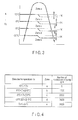
FIG. 3 is a view for showing a relationship between a temperature detected by a refrigerant temperature sensor in each of the embodiments and a plurality of zones set for the detected temperature; -
FIG. 4 is a view for showing conditions for setting the number of revolutions of a circulating pump in each of the embodiments; -
FIG. 5 is a view for showing a relationship between a temperature detected by a temperature sensor in each of the embodiments and a plurality of zones set for the detected temperature; -
FIG. 6 is a view for showing conditions for correcting the number of revolutions of the circulating pump in each of the embodiments; and -
FIG. 7 is a flowchart of a control in the second embodiment. - In general, according to one embodiment, a hot-water supply apparatus includes: a hot-water supply tank; a heat-pump type refrigeration cycle which comprises a compressor configured to compress and discharge refrigerant, and in which the compressor, a four-way valve, a water heat exchanger, an open/close valve, a pressure reducing unit and an outdoor heat exchanger are connected in this order; a bypass connected between the open/close valve and the pressure reducing unit and between the four-way valve and the water heat exchanger; a circulating pump configured to circulate water in the supply-water tank after making the water pass through the water heat exchanger; a refrigerant temperature sensor configured to detect a temperature of the refrigerant when the refrigerant flows between the water heat exchanger and the open/close valve; and a control section configured to perform a defrosting operation of defrosting the outdoor heat exchanger by activating a defrosting circuit in which the refrigerant discharged from the compressor flows through the four-way valve, the outdoor heat exchanger, the pressure reducing unit, the bypass and the four-way valve and returns to the compressor, and also configured to operate the circulating pump in a case where the temperature detected by the refrigerant temperature sensor lowers to be less than a set value during the defrosting operation.
- A hot-water supply apparatus according to a first embodiment will be explained.
- The hot-water supply apparatus, as shown in
FIG. 1 , comprises anoutdoor unit 10, a waterheat exchanging unit 20 and a hot-watersupply tank unit 30, which are connected to each other by pipes specific for those units. Also, acontrol section 50 is connected to theoutdoor unit 10, the waterheat exchanging unit 20 and the hot-watersupply tank unit 30. To thecontrol section 50, an operation anddisplay section 51 is connected. - The
outdoor unit 10 and the waterheat exchanging unit 20 are connected as described above to provide a heat-pump type refrigeration cycle. - A
compressor 11 is provided to discharge refrigerant after sucking therein and compressing the refrigerant. To a discharge portion of thecompressor 11, a four-way valve 12 and one end of awater heat exchanger 22 are connected by a pipe specific for them, with an open/close valve, e.g., a two-way valve 21, interposed between the four-way valve 12 and thewater heat exchanger 22. To the other end of thewater heat exchanger 22, one end of anoutdoor heat exchanger 14 is connected by a pipe specific for them, with a pulse motor valve (PMV) 23 and a pressure reducing unit, e.g., anelectrical expansion valve 13, interposed between thewater heat exchanger 22 and theoutdoor heat exchanger 14. The other end of theoutdoor heat exchanger 14 is connected to an intake port of thecompressor 11 by a pipe specific for them, with the four-way valve 12 interposed between theoutdoor heat exchanger 14 and thecompressor 11. - When a heat operation is performed, i.e., a heating circuit is activated, as indicated by arrows of solid lines, refrigerant (gas refrigerant) having a high temperature discharged from the
compressor 11 passes through the four-way valve 12 and the two-way valve 21 to flow into thewater heat exchanger 22. In thewater heat exchanger 22, the refrigerant is liquefied by heat exchange between the refrigerant and water. The liquefied refrigerant passes through thepulse motor valve 23 and the electrical expansion valve 13 (e.g., a pulse motor valve) to flow into theoutdoor heat exchanger 14. In theoutdoor heat exchanger 14, the refrigerant is gasified by absorbing heat from outside air in theoutdoor heat exchanger 14. After passing through the four-way valve 12, the gasified refrigerant is sucked in thecompressor 11. In such a manner, when the heating circuit is activated, water passing through thewater heat exchanger 22 is heated. - The two-
way valve 21 is an electromagnetic type of two-way valve which is opened by supplying power to the two-way valve 21, and closed by stopping supplying of the power thereto. To be more specific, the two-way valve 21 is opened when the above heating circuit is activated, and closed to stop flowing of the refrigerant into thewater heat exchanger 22 at a pipe for gas in the heat-pump type refrigeration cycle when a defrosting circuit is activated which will be described later. The degree of opening of thepulse motor valve 23 is continuously varied in accordance with the number of drive voltage pulses. Thepulse motor valve 23 is totally opened when the heating circuit is activated, and totally closed to stop flowing of the refrigerant into thewater heat exchanger 22 at a pipe for liquid in the heat-pump type of refrigeration circuit when the defrosting circuit is activated. - In the above heat-pump type refrigeration cycle, a
bypass 24 for the defrosting circuit, which includes acheck valve 24a, is provided to extend from a pipe for liquid between thepulse motor valve 23 and theelectrical expansion valve 13 to a pipe for gas between the four-way valve 12 and the two-way valve 21. - When the four-
way valve 12 is switched, the two-way valve 21 is closed, and thepulse motor valve 23 is totally closed, as indicated by arrows of broken lines, the refrigerant discharged from thecompressor 11 passes through the four-way valve 12 to directly flow into theoutdoor heat exchanger 14. After passing through theoutdoor heat exchanger 14, the refrigerant passes through theelectrical expansion valve 13, thebypass 24 and the four-way valve 12, and is then sucked in thecompressor 11. This is achieved when the defrosting circuit is activated. That is, when the defrosting circuit is activated, it causes frost formed on theoutdoor heat exchanger 14 to be removed by heat of the refrigerant having a high temperature supplied from thecompressor 11. - The hot-water
supply tank unit 30 comprises a hot-water supply tank 31. To lower part and upper part of the hot-water supply tank 31, anincurrent pipe 41 and anexcurrent pipe 42 are connected respectively. Theincurrent pipe 41 guides water of a water supply source to the lower part of the hot-water supply tank 31. Theexcurrent pipe 42 guides hot water in the upper part of the hot-water supply tank 31 to a load. - An
incurrent pipe 32 is provided to extend from the lower part of the hot-water supply tank 31 to one end of a water way of thewater heat exchanger 22. Also, anexcurrent pipe 33 is provided to extend from the other end of the water way of thewater heat exchanger 22 to the upper part of the hot-water supply tank 31. At theincurrent pipe 32, a circulatingpump 27 for water supply is provided. When the circulatingpump 27 is operated, it causes hot water in the hot-water supply tank 31 to pass through thewater heat exchanger 22, and to be circulated. - Furthermore, in the
outdoor unit 10, at a pipe for discharge, which extends between the discharge port of thecompressor 11 and the four-way valve 12, a refrigerant-temperature sensor 15 is provided to detect a temperature Td of the refrigerant discharged from thecompressor 11. At a pipe for intake, which extends between the four-way valve 12 and thecompressor 11, a refrigerant temperature sensor 16 is provided to detect a temperature Ts of the refrigerant sucked in thecompressor 11. In addition, an outside-air temperature sensor 17 is provided close to theoutdoor heat exchanger 14 to detect an outside air temperature To. At theoutdoor heat exchanger 14, a heat-exchange temperature sensor 18 is provided to detect a temperature T2 of theoutdoor heat exchanger 14. - In the water
heat exchanging unit 20, a heat-exchange sensor 25 is attached to thewater heat exchanger 22 to a temperature Tc of thewater heat exchanger 22. At a pipe for liquid which extends between thewater heat exchanger 22 and thepulse motor valve 23, arefrigerant temperature sensor 26 is provided to detect a temperature Tx of the refrigerant. At theincurrent pipe 32, awater temperature sensor 28 is provided to detect a temperature Twi of water which will flow into thewater heat exchanger 22. At theexcurrent pipe 33, awater temperature sensor 29 is provided to detect a temperature Two of water which has flowed out from thewater heat exchanger 22. - At the hot-water
supply tank unit 30, anelectric heater 34 for heating hot water is provided in the hot-water supply tank 31. Also, awater temperature sensor 35 configured to detect a temperature Tt of water in theelectric heater 34 is attached to lower part of the hot-water supply tank 31. - The
control section 50 comprises a microcomputer and a peripheral circuit thereof. To be more specific, thecontrol section 50 comprises a random-access memory (RAM) which is a volatile memory, as storage section, and also anelectrolytic capacitor 53 as a power supply for operating theRAM 52. - Furthermore, the
control section 50 comprises, as main means thereof, the following sections (1)-(7): - (1) a heating operation section configured to activate a heating circuit in which the refrigerant discharged from the
compressor 11 passes through the four-way valve 12, the two-way valve 21, thewater heat exchanger 22, thepulse motor valve 23, theelectrical expansion valve 13, theoutdoor heat exchanger 14 and the four-way valve 12 and returns to thecompressor 11, and also to operate the circulatingpump 27, in order to heat water in the hot-water supply tank 31; - (2) a defrosting operation section configured to activate a defrosting circuit in which the refrigerant discharged from the
compressor 11 passes through the four-way valve 12, theoutdoor heat exchanger 14, theelectrical expansion valve 13, thebypass 24 and the four-way valve 12 and returns to thecompressor 11, in order to remove frost formed on theoutdoor heat exchanger 14, the defrosting operation section being further configured to close thepulse motor valve 23 and the two-way valve 21 at the time of performing the above defrosting operation; - (3) a first control section configured to cause the heating operation of the heating operation section and the defrosting operation of the defrosting operation section to be selectively performed;
- (4) a second control section configured to operate the circulating
pump 27 if the temperature Tx detected by therefrigerant temperature sensor 26 lowers to be equal to or less than a set value during the defrosting operation; - (5) a third control section configured to control the number of revolutions of the circulating
pump 27 which is operated during the defrosting operation, in accordance with the temperature Tx detected by therefrigerant temperature sensor 26; - (6) a fourth control section configured to correct the number of revolutions of the circulating
pump 27 which is controlled by the third control section, in accordance with the temperature Twi detected by thewater temperature sensor 28; and - (7) a first control section configured to stop, if the temperature tx detected by the
refrigerant temperature sensor 26 lowers to be lower than a predetermined value lower than the above set value, the operation of thecompressor 11; once totally operate thepulse motor valve 23 and then totally close it (initializing operation); and thereafter restart the operation of thecompressor 11. - Next, the operation will be explained with reference to the flowchart of
FIG. 2 . - When a hot-water supply tap on a load side is opened, hot water in the upper part of the hot-
water supply tank 31 flows to the load through theexcurrent pipe 42. Thus, water is resupplied from the water supply source into the lower part of the hot-water supply tank 31 through theincurrent pipe 41. - The temperature Tt of water in the hot-
water supply tank 31 is detected by thewater sensor 35. When the temperature Tt detected by thewater sensor 35 becomes lower than a temperature set by the operation of the operation anddisplay section 51, thecompressor 11 is operated to provide the heating circuit, and the circulatingpump 27 is also operated. Due to the heating operation by the heating circuit and the circulatingpump 27, water in the hot-water supply tank 31 is heated. When this heating operation continues, and the temperature Tt detected by thewater sensor 35 rises to be higher than the set value, thecompressor 11 is stopped to deactivate the heating circuit, and the circulatingpump 27 is also stopped. - During the heating operation, in the case where the temperature of outside air is low, frost gradually forms on a surface of the
outdoor heat exchanger 14, which functions as an evaporator. In accordance with formation of the frost, the temperature Te of theoutdoor heat exchanger 14 lowers. - The temperature Te of the
outdoor heat exchanger 14 is detected by the heat-exchange temperature sensor 18. In the case where a defrosting condition is satisfied in which the temperature Te detected by the heat-exchange temperature sensor 18 lowers to be equal to or lower than a set value (e.g., 0°C), and this state continues for a predetermined time period (Yes in step 101), the defrosting circuit is activated, and the defrosting operation for theoutdoor heat exchanger 14 is started (step 102). - At the time of performing the defrosting operation, the circulating
pump 27 is stopped to also stop circulation of water to thewater heat exchanger 22, and the two-way valve 21 is closed to totally close thepulse motor valve 23. That is, thepulse motor valve 23 is totally closed in order to prevent the refrigerant whose temperature lowers due to the defrosting operation for theoutdoor heat exchanger 14 from flowing into thewater heat exchanger 22. Furthermore, in the defrosting circuit, since the refrigerant flows toward the four-way valve 12 through thebypass 24, if the two-way valve 21 is kept opened, there is a possibility that a negative pressure will be applied to thepulse motor valve 23 through thewater heat exchanger 22, and the refrigerant will leak from thepulse motor valve 23 due to the applied negative pressure. In order to prevent such a problem, the two-way valve 21 is closed. - However, there is a case where for example, dust is caught in the
pulse motor valve 23 or the number of drive voltage pulses applied in a control of the degree of the opening of thepulse motor valve 23 varies from a set number of pulses, as a result of which thepulse motor valve 23, which should be totally closed, is opened to permit the refrigerant to leak therefrom. In this case, there is a case where the leaking refrigerant will flow into thewater heat exchanger 22, and ice thewater heat exchanger 22. - In order to avoid such a problem, during the defrosting operation, the circulating
pump 27 is controlled based on the temperature Tx detected by therefrigerant temperature sensor 26 at the pipe for liquid between thepulse motor valve 23 and the water heat exchanger 22 (step 200). - In the above circulation-pump control, temperature zone conditions as shown in
FIG. 3 and number-of-revolutions conditions as shown inFIG. 4 are applied. To be more specific, as the temperature zone conditions, a relationship between the temperature Tx detected by therefrigerant temperature sensor 26 and a plurality of zones a, b, c, d and e set for the detected temperature Tx is established as shown inFIG. 3 , and as the number-of-revolutions conditions, the number of revolutions of the circulatingpump 27 is determined with respect to each of the above zones as shown inFIG. 4 . - Under the temperature zone conditions shown in
FIG. 3 , a temperature difference of 1K (hysteresis) is ensured between each of boundaries between the zones which are set with respect to the case where the detected temperature Tx rises and a respective one of boundaries between the zones which are set with respect to the case where the detected temperature Tx lowers, as shown inFIG. 3 . - For example, in the case where the detected temperature Tx rises, -25°C is determined as a boundary from the zone e to the zone d, -5°C is determined as a boundary from the zone d to the zone c, 0°C is determined as a boundary from the zone c to the zone b, and 10°C is determined as a boundary from the zone b to the zone a. In the case where the detected temperature Tx lowers, 9°C is determined as a boundary from the zone a to the zone b, -1°C is determined as a boundary from the zone b to the zone c, -6°C is set as a boundary from the zone c to the zone b, and -26°C is set as a boundary from the zone d to the zone e.
- If the detected temperature Tx falls within the zone a (Yes in step 201), it is determined that refrigerant does not leak from the
pulse motor valve 23, and the number of revolutions of the circulatingpump 27 is set to zero (step 202). - If the detected temperature Tx falls within the zone b lower than the zone a (Yes in step 203), it is determined that a small amount of refrigerant leaks from the
pulse motor valve 23, and the circulatingpump 27 is operated at 1300 rpm (step 204). This causes water in the hot-water supply tank 31 to flow into thewater heat exchanger 22, and restricts lowering of the temperature of thewater heat exchanger 22 due to leakage of the above small amount of refrigerant from thepulse motor valve 23. - If the detected temperature Tx falls within the zone c lower than the zone b (Yes in step 205), it is determined that the amount of refrigerant leaking from the
pulse motor valve 23 is larger than the above small amount of refrigerant, and the circulatingpump 27 is operated at 2600 rpm (step 206). In such a manner, when the number of revolutions of the circulatingpump 27 is increased, the amount of water flowing into thewater heat exchanger 22 is also increased to be larger than that in the case where the detected temperature Tx falls within the zone b. Thereby, even if the amount of refrigerant leaking from thepulse motor valve 23 is larger than the above small amount of refrigerant, lowering of the temperature of thewater heat exchanger 22 is restricted. - If the detected temperature Tx falls within the zone d lower than the zone c (Yes in step 207), it is determined that the amount of refrigerant leaking from the
pulse motor valve 23 is much larger than the above small amount of refrigerant, and the circulatingpump 27 is operated at 3420 rpm (step 208). In such a manner, when the number of revolutions is increased, the amount of water flowing into thewater heat exchanger 22 is also increased to be larger than that in the case where the detected temperature Tx falls within the zone c. Therefore, even if the amount of refrigerant leaking from thepulse motor valve 23 is much larger than the above small amount of refrigerant, lowering of the temperature of thewater heat exchanger 22 is restricted. - In such a manner, lowering of the temperature of the
water heat exchanger 22 can be restricted, and thus thewater heat exchanger 22 is prevented from being iced. As a result, water in the hot-water supply tank 31 can be reliably heated, and the reliability of the hot-water supply apparatus is improved. - If the detected temperature Tx falls within the zone e lower than the zone d (No in step 207), it is determined that a considerably large amount of refrigerant leaks from the
pulse motor valve 23, and the operation of thecompressor 11 is stopped. In this state, initialization processing is executed in which thepulse motor valve 23 is totally opened once, and then totally closed; and thereafter the operation of thecompressor 11 is restarted (step 209). - In the case where dust is caught in the
pulse motor valve 23 to cause refrigerant to leak from thepulse motor valve 23, the dust is swept away from thepulse motor valve 23 when thepulse motor valve 23 is totally opened by the above initialization processing. As a result, thepulse motor valve 23 is reliably totally opened to prevent leakage of the refrigerant. - Also, in the case where the number of drive voltage pulses applied to the
pulse motor valve 23 varies from a set number of pulses to cause refrigerant to leak from thepulse motor valve 23, thepulse motor valve 23 is totally opened once and then totally closed by the initialization processing, as a result of which the number of drive voltage pulses applied to thepulse motor valve 23 coincides with the set number of pulses. Thereby, thepulse motor valve 23 is reliably totally closed, thus preventing leakage of the refrigerant. - Since the refrigerant is prevented from leaking from the
pulse motor valve 23, thewater heat exchanger 22 is also prevented from being iced. In addition, water in the hot-water supply tank 31 can be reliably heated. - On the other hand, in the operation of the circulating
pump 27 and the control of the number of revolutions thereof, the temperature Twi of water which will flow from the hot-water supply tank 31 into thewater heat exchanger 22 is detected by thewater temperature sensor 28. Based on the temperature Twi detected by thewater temperature sensor 28, a control value for the number of revolutions by the circulating-pump control instep 200 is corrected. - In this correction, temperature zone conditions as shown in
FIG. 6 and number-of-revolutions conditions as shown inFIG. 7 are applied. To be more specific, as the temperature zone conditions, a relationship between the temperature Twi detected by thewater temperature sensor 28 and a plurality of zones A and B set for the detected temperature Twi is established as shown inFIG. 6 , and as the number-of-revolutions conditions, a correction value of the number of revolutions is determined with respect to each of the zones as shown inFIG. 7 . - Under the temperature zone conditions as shown in
FIG. 6 , a temperature difference of 1K (hysteresis) is ensured between each of boundaries between the zones which are set with respect to the case where the detected temperature Twi rises and a respective one of boundaries between the zones which are set with respect to the case where the detected temperature Twi lowers, as shown inFIG. 6 . - For example, in the case where the detected temperature Twi rises, 5°C is determined as a boundary from an unavailable zone to the zone A, and 10°C is determined as a boundary from the zone A to the zone B. In the case where the detected temperature Twi lowers, 9°C is determined as a boundary from the zone B to the zone A, and 5°C is determined as a boundary from the zone A to the unavailable zone.
- More specifically, if the detected temperature Twi falls within the zone A lower than 10°C (Yes in step 201), a correction value for the number of revolutions is one times the control value for the number of revolutions, i.e., it is equal to the control value, and is not corrected. If the detected temperature Twi exceeds 10°C to fall within the zone B (No in step 201), the correction value for the number of revolutions is 0.6 times the control value therefore. In this case, for example, if the control value is 1300 rpm, the actual number of revolutions of the circulating
pump 27 is set to 780 rpm which is 0.6 times the control value. If the control value is 2600 rpm, the actual number of revolutions of the circulatingpump 27 is set to 1560 rpm which is 0.6 times the control value. If the control value is 3420 rpm, the actual number of revolutions of the circulatingpump 27 is set to 2052 rpm which is 0.6 times the control value. - In the case where the detected temperature Twi is higher than 10°C, it is determined that even if the amount of water to flow into the
water heat exchanger 22 is decreased, lowering of the temperature of thewater heat exchanger 22 can be restricted. Based on this determination, the number of revolutions of the circulatingpump 27 is corrected to be decreased. This correction enables the power required to operate the circulatingpump 27 to be reduced as much as possible, thus achieving energy saving. - If the defrosting operation for the
outdoor heat exchanger 14 advances, and the temperature Te detected by the heat-exchange temperature sensor 18 exceeds the set value, e.g., 8°C (Yes in step 212), the defrosting circuit is deactivated to end the defrosting operation (step 103). As a result, the heating operation is restarted as appropriate in accordance with the temperature Tt detected by thewater sensor 35. - A second embodiment will be explained.
- In addition to the sections (1)-(7) provided with respect to the first embodiment, the
control section 50 further comprises the following sections (8)-(11): - (8) a sixth section configured to make a check to determine whether the
refrigerant temperature sensor 26 has abnormality or not based on the temperature detected by therefrigerant temperature sensor 26, while operating the circulatingpump 27 at a predetermined number of revolutions, e.g., 342 rpm, with thepulse motor valve 23 opened at an predetermined degree of opening, e.g., a degree of opening corresponding to 100 pulses, at at least an initial stage of shifting from the heating operation to the defrosting operation; - (9) a seventh control section configured to cause the defrosting operation to continue, and also an
RAM 52 to hold a check completion flag on to indicate that the check is completed, when the sixth control section determines that therefrigerant temperature sensor 26 does not have abnormality; and stop all operations including the defrosting operation (stop due to abnormality) when the sixth control section determines that therefrigerant temperature sensor 26 has abnormality; - (10) an eighth control section configured to make, when during the heating operation, the check completion flag of the
RAM 52 is held on to indicate that the above check is completed, a simply check to determine whether therefrigerant temperature sensor 26 has abnormality or not based on a variation of the temperature Tx detected by therefrigerant temperature sensor 26; and - (11) a ninth control section configured to hold the check completion flag of the
RAM 52 on when the eighth control section determines that therefrigerant temperature sensor 26 does not have abnormality; and clear the check completion flag held on in theRAM 52 when the eighth control sections determines that therefrigerant temperature sensor 26 has abnormality. - The
RAM 52 in thecontrol section 50 functions as a storage section configured to hold the check completion flag on to indicate that the check on whether the sensor has abnormality or not is completed. Furthermore, theRAM 52 can hold the contents of stored information for approximately 12 hours due to charge remaining in theelectrolytic capacitor 53 even if supply of power is stopped by turning off a power supply switch or a commercial alternating-current power supply is instantly interrupted. - The other structural features of the second embodiment are the same as those of the first embodiment, and their explanations will thus be omitted.
- With respect to the operation, as shown in the flowchart of
FIG. 7 , astep 300 is added as a sensor-abnormality checking control between thestep 102 in which the defrosting operation is started and thestep 200 in which the circulating-pump control is performed. In thestep 300, a check is made to determine whether therefrigerant temperature sensor 26 has abnormality or not. - To be more specific, during the heating operation, if the temperature Te of the
outdoor heat exchanger 14 which is detected by the heat-exchange temperature sensor 18 lowers to be lower than a set value (e.g., 0°C), and this state continues for the predetermined time period; that is, the defrosting condition is satisfied (Yes in step 101), the defrosting circuit is activated to start the defrosting operation on the outdoor heat exchanger 14 (step 102). When the defrosting operation starts, the above sensor-abnormality checking control is performed to determine whether therefrigerant temperature sensor 26 has abnormality or not (step 300). - In the sensor-abnormality checking control, first, it is monitored whether the check completion flag of the
RAM 52 is on or not (step 301). If it takes long time until the heating operation is started just after the power supply switch is turned on or just after the commercial AC power supply is recovered from instant interruption thereof, the charge remaining in theelectrolytic capacitor 53 is lost, and the information in theRAM 52 is erased. In this case, the check completion flag of theRAM 52 is off. - If the check completion flag of the
RAM 52 is off (No in step 301), it is determined that it indicates an initial stage of shifting from the heating operation to the defrosting operation, thepulse motor valve 23 is opened to a predetermined degree of opening, e.g., a degree of opening corresponding to 100 pulses (step 302), the circulatingpump 27 is started, and the number of revolutions thereof is set to a predetermined number of revolutions, e.g., 3420 rpm (step 303). - The degree of opening corresponding to 100 pulses is a degree of opening at which the
pulse motor valve 23 is opened to permit a small amount of low-temperature refrigerant flowing from theoutdoor heat exchanger 14 to pass through thepulse motor valve 23, by applying 100 drive voltage pulses to thepulse motor valve 23. At this time, in order to restrict lowering of the temperature of thewater heat exchanger 22 due to the low-temperature refrigerant flowing into thewater heat exchanger 22, the circulatingpump 27 is started and operated at 3420 rpm. Thereby, water in the hot-water supply tank 31 passes through thewater heat exchanger 22 and circulates. - When the
pulse motor valve 23 is opened in accordance with application of 100 drive voltage pulses in the above manner, it is determined whether the temperature Tx detected by therefrigerant temperature sensor 26 lowers to be lower than, e.g., -5°C which is a set value for checking abnormality (step 304). In the case where the detected temperature Tx lowers to be lower than -5°C (Yes in step 304), it is determined that therefrigerant temperature sensor 26 is normal, and also determined that the check on therefrigerant temperature sensor 26 is completed. As a result, the check completion flag of theRAM 52 is made on (step 306). - Even in the case where the detected temperature Tx does not lower to be lower than -5°C (No in step 304), if it is lower than the temperature Txo detected by the
refrigerant temperature sensor 26 before the above defrosting operation, and the difference between the detected temperatures Tx and Txo exceeds 25K (Yes in step 305), it is determined that therefrigerant temperature sensor 26 is normal, and also determined that the check on therefrigerant temperature sensor 26 is completed. As a result, the check completion flag of theRAM 52 is made on (step 306). - When the check completion flag is made on, the circulating-pump control accompanying the defrosting operation is performed (step 200). The circulating-pump control is the same as that of the first embodiment, and its explanation will thus be omitted.
- When the defrosting operation for the
outdoor heat exchanger 14 advances, and the temperature Te detected by the heat-exchange temperature sensor 18 exceeds the set value, e.g., 8°C, the defrosting circuit is deactivated to end the defrosting operation (step 103). As a result, the heating operation is restarted as appropriate in accordance with the temperature Tt detected by thewater sensor 35. - After the restart of the heating operation, when the defrosting condition is satisfied (Yes in step 101), a second defrosting operation is started (step 102). At this time, since the check completion flag of the
RAM 52 is on (Yes in step 301), the circulating-pump control is performed (step 200) without performing the check from thestep 302. - On the other hand, at the time of performing the first defrosting operation, if the detected temperature Tx does not lower less than -5°C (No in step 304) or the difference between the detected temperature Tx and the temperature Tx0 detected by the
refrigerant temperature sensor 26 before the first defrosting operation does not exceed -25K (Yes in step 305), and then if three minutes elapse from the time the first defrosting operation starts (Yes in step 307), it is determined that therefrigerant temperature sensor 26 is abnormal. Based on this determination, thecompressor 11 is stopped, all operations including the first defrosting operation are stopped (due to abnormality), and this stop is indicated by the operation and display section 51 (step 308). For example, therefrigerant temperature sensor 26 can have the following abnormalities: the detection function of therefrigerant temperature sensor 26 itself fails; therefrigerant temperature sensor 26 is detached from the pipe due to vibration or the like; and a signal line for transmitting a detection signal from therefrigerant temperature sensor 26 is cut. - A user who uses the hot-water supply apparatus knows from the display of the operation and
display section 51 why all the operations are stopped, and can thus ask a maker or a distributor for the hot-water supply apparatus to, e.g., inspect or repair the hot-water supply apparatus in order to maintain it. Until this maintenance is performed, all the operations are kept stopped. - Therefore, the defrosting operation is not performed, with abnormality occurring in the
refrigerant temperature sensor 26. Thus, thewater heat exchanger 22 can be reliably prevented from being iced. Accordingly, water in the hot-water supply tank 31 can be heated reliably. - It should be noted that there is a case where the first defrosting operation for the
outdoor heat exchanger 14 advances in a state in which the detected temperature Tx does not lower less than -5°C (No in step 304) or the difference between the detected temperature Tx and the temperature Tx0 detected by therefrigerant temperature sensor 26 before the first defrosting operation does not exceed -25K (Yes in step 305), and three minutes do not elapse from the time the first defrosting operation is started (No in step 307); and as a result the temperature Te detected by the heat-exchange temperature sensor 18 exceeds the set value, e.g., 8°C (Yes in step 309). In this case, it is determined that the check on therefrigerant temperature sensor 26 is not completed, and the check completion flag of theRAM 52 is kept off (step 310). Then, the defrosting circuit is deactivated to end the defrosting operation (step 103). As a result, the heating operation is restarted as appropriate in accordance with the temperature Tt detected by thewater sensor 35. - In the case where the defrosting operation is restarted after the restart of the heating operation; i.e., the second defrosting operation is started, the check completion flag of the
RAM 52 is kept off (No in step 301). Thus, the check from thestep 302 is repeated. - Also, it should be noted that the check completion flag of the
RAM 52 is kept on for approximately 12 hours due to the charge remaining in theelectrolytic capacitor 53, even if the power supply switch is turned off or the commercial AC power supply is instantly interrupted. Thus, after the heating operation is started (thecompressor 11 is operated) upon turning on of the power supply switch or recovery of the commercial AC power supply from instant interruption, if the check completion flag of theRAM 52 is kept on, the check is not made even if the defrosting operation is started. Thus, there is a possibility that unexpected abnormality of therefrigerant temperature sensor 26 will be overlooked. - In view of the above, in the checking control of checking whether the sensor has abnormality or not, at the time of performing the heating operation (Yes in step 311), in the case where the check completion flag of the
RAM 52 is kept on to indicate that the check is completed (Yes in step 312), the simply check on therefrigerant temperature sensor 26 is made. - To be more specific, where Txa is a temperature detected by the
refrigerant temperature sensor 26 just after the heating operation is started (just after thecompressor 11 is operated) (the detected temperature being the temperature of refrigerant flowing from thewater heat exchanger 22 toward the pulse motor valve 23) and Txb is a temperature detected by therefrigerant temperature sensor 26 during the heating operation (the detected temperature being also the temperature of the refrigerant flowing from thewater heat exchanger 22 toward the pulse motor valve 23), the difference between the above detected temperatures (Txb - Txa) exceeds 3K (Yes in step 313), it is determined that therefrigerant temperature sensor 26 properly detects the temperature of the refrigerant, i.e., it does not have abnormality, and thus the check completion flag of theRAM 52 is kept on (step 314). - However, in the case where the difference between the above detected temperatures (Txb - Txa) does not exceed 3K (Yes in step 313), and a predetermined time period, e.g., 5 minutes, elapses from the time when the heating operation is started (Yes in step 315), it is determined that the
refrigerant temperature sensor 26 has abnormality due to which it cannot properly detect the temperature of the refrigerant, and the check completion flag of theRAM 52 which is on is cleared (step 316). That is, the check completion flag of theRAM 52 is made off. - When the check completion flag is made off to shift the operation from the heating operation to the defrosting operation, the check from the
step 302 is made, and it is checked whether therefrigerant temperature sensor 26 has abnormality or not. - Therefore, even if unexpected abnormality occurs in the
refrigerant temperature sensor 26 during the heating operation, it is not overlooked, i.e., it is reliably detected. Thus, the circulating-pump control is improved as a control for preventing icing of thewater heat exchanger 22. - With respect to each of the first and second embodiments, in the circulating-pump control, the number of revolutions of the circulating
pump 27 can be varied in three stages: 1300 rpm; 2600 rpm; and 3420 rpm. However, the value to which the number of revolutions can be varied is not limited to the above values, and the number of stages in which it can be varied is not limited to three. They may be determined as appropriate in accordance with the capacity of the circulatingpump 27, the diameter of each of theincurrent pipe 32 and theexcurrent pipe 33, or the capacity of thewater heat exchanger 22. - While certain embodiments have been described, these embodiments have been presented by way of example only, and are not intended to limit the scope of the inventions. Indeed, the novel embodiments described herein may be embodied in a variety of other forms; furthermore, various omissions, substitutions and changes in the form of the embodiments described herein may be made without departing from the spirit of the inventions. The accompanying claims and their equivalents are intended to cover such forms or modifications as would fall within the scope and spirit of the inventions.
Claims (15)
- A hot-water supply apparatus characterized by comprising:a hot-water supply tank (31);a heat-pump type refrigeration cycle which comprises a compressor (11) configured to compress and discharge refrigerant, and in which the compressor (11), a four-way valve (12), a water heat exchanger (22), an open/close valve (23), a pressure reducing unit (13) and an outdoor heat exchanger (14) are connected in this order;a bypass (24) connected between the open/close valve (23) and the pressure reducing unit (13) and between the four-way valve (12) and the water heat exchanger (22);a circulating pump (27) configured to circulate water in the supply-water tank (31) after making the water pass through the water heat exchanger (22);a refrigerant temperature sensor (26) configured to detect a temperature of the refrigerant when the refrigerant flows between the water heat exchanger (22) and the open/close valve (23); anda control section (50) configured to perform a defrosting operation of defrosting the outdoor heat exchanger (14) by activating a defrosting circuit in which the refrigerant discharged from the compressor (11) flows through the four-way valve (12), the outdoor heat exchanger (14), the pressure reducing unit (13), the bypass (24) and the four-way valve (12) and returns to the compressor (11), and also configured to operate the circulating pump (27) in a case where the temperature detected by the refrigerant temperature sensor (26) lowers to be less than a set value during the defrosting operation.
- The apparatus of claim 1, characterized in that the control section (50) performs a heating operation of heating the water in the hot-water supply tank (31) by activating a heating circuit in which the refrigerant discharged from the compressor (11) passes through the four-way valve (12), the water heat exchanger (22), the open/close valve (23), the pressure reducing unit (13), the outdoor heat exchanger (14) and the four-way valve (12) and returns to the compressor, and also by operating the circulating pump (27).
- The apparatus of claim 1, characterized in that the bypass (24) includes a check valve (24a).
- The apparatus of claim 1, characterized in that the control section (50) closes the open/close valve (23) at time of performing the defrosting operation.
- The apparatus of claim 1, characterized in that the heat-pump type refrigeration cycle includes an open/close valve (21) between the four-way valve (12) and the water heat exchanger (22).
- The apparatus of claim 1, characterized in that the control section (50) closes the open/close valve (23) and the close/open valve (21) at time of performing the defrosting operation.
- The apparatus of claim 5, characterized in that the open/close valve (21) is a two-way valve, and the open/close valve (23) is a pulse motor valve which is continuously variable in degree of opening.
- The apparatus of claim 1, characterized in that the control section (50) controls a number of revolutions of the circulating pump (27) in accordance with the temperature detected by the refrigerant temperature sensor (26) when the circulating pump (27) is operated at time of performing the defrosting operation.
- The apparatus of claim 1, which further comprises a water temperature sensor configured to detect a temperature of the water before the water flows into the water heat exchanger (22), and characterized in that the control section (50) controls a number of revolutions of the circulating pump (27) in accordance with the temperature detected by the refrigerant temperature sensor (26) when the circulating pump (27) is operated at time of performing the defrosting operation, and also corrects the controlled number of revolutions in accordance with the temperature detected by the water temperature sensor (25).
- The apparatus of claim 1, characterized in that the open/close valve (23) is a pulse motor valve which is continuously variable in degree of opening.
- The apparatus of claim 10, characterized in that at time of performing the defrosting operation, if the temperature detected by the refrigerant temperature sensor (26) lowers to be less than a predetermined value lower than the set value, the control section (50) stops an operation of the compressor (11) and totally closes the pulse motor valve (23) after totally opening the pulse motor valve (23); and therafter, restarts the operation of the compressor (11).
- The apparatus of claim 10, characterized in that at at least an initial stage of shifting from the heating operation to the defrosting operation, while operating the circulating pump (27) at a predetermined number of revolutions, with the pulse motor valve (23) opened at a predetermined degree of opening, the control section (50) makes a check on the refrigerant temperature sensor (26) based on the temperature detected by the refrigerant temperature sensor (26) to determine whether the refrigerant temperature sensor (26) has abnormality or not; and if determining that the refrigerant temperature sensor (26) does not have abnormality, the control section (50) causes the defrosting operation to continue, and holds in a storage section (52), information indicating that the check is completed, and if determining that the refrigerant temperature sensor (26) has abnormality, the control section (50) stops all operations including the defrosting operation.
- The apparatus of claim 12, characterized in that at time of performing the heating operation, if the information held in the storage section (52) indicates that the check is completed, the control section (50) makes a simple check on the refrigerant temperature sensor (26) based on the temperature detected by the refrigerant temperature sensor (26) to determine whether the refrigerant temperature sensor (26) has abnormality or not; and if determining that the refrigerant temperature sensor (26) does not have abnormality, the control section (50) maintains the information in the storage section (52), and if determining that the refrigerant temperature sensor (26) has abnormality, the control section (52) clears the information in the storage section (52).
- A control method of a hot-water supply apparatus which comprises:a hot-water supply tank (31);a heat-pump type refrigeration cycle which comprises a compressor (11) configured to compress and discharge refrigerant, and in which the compressor (11), a four-way valve (12), a water heat exchanger (22), an open/close valve (23), a pressure reducing unit (13) and an outdoor heat exchanger (14) are connected in this order;a bypass (24) connected between the open/close valve (23) and the pressure reducing unit (13) and between the four-way valve (12) and the water heat exchanger (22);a circulating pump (27) configured to circulate water in the supply-water tank (31) after making the water pass through the water heat exchanger (22); anda refrigerant temperature sensor (26) configured to detect a temperature of the refrigerant when the refrigerant flows between the water heat exchanger (22) and the open/close valve (23),
the control method characterized by comprising:defrosting the outdoor heat exchanger (14) by activating a defrosting circuit in which the refrigerant discharged from the compressor (11) flows through the four-way valve (12), the outdoor heat exchanger (14), the pressure reducing unit (13), the bypass (24) and the four-way valve (12) and returns to the compressor (11); andoperating the circulating pump (27) if at time of defrosting the outdoor heat exchanger (14), the temperature detected by the refrigerant temperature sensor (26) lowers to be less than a set value. - The method of claim 14, characterized by further comprising heating the hot-water supply tank (31) by activating a heating circuit in which the refrigerant discharged from the compressor (11) passes through the four-way valve (12), the water heat exchanger (22), the open/close valve (23), the pressure reducing unit (13), the outdoor heat exchanger (14) and the four-way valve (12) and returns to the compressor, and also by operating the circulating pump (27).
Applications Claiming Priority (1)
| Application Number | Priority Date | Filing Date | Title |
|---|---|---|---|
| JP2012237624A JP5978099B2 (en) | 2012-10-29 | 2012-10-29 | Water heater |
Publications (3)
| Publication Number | Publication Date |
|---|---|
| EP2725305A2 true EP2725305A2 (en) | 2014-04-30 |
| EP2725305A3 EP2725305A3 (en) | 2018-03-21 |
| EP2725305B1 EP2725305B1 (en) | 2019-12-11 |
Family
ID=49447986
Family Applications (1)
| Application Number | Title | Priority Date | Filing Date |
|---|---|---|---|
| EP13189357.0A Active EP2725305B1 (en) | 2012-10-29 | 2013-10-18 | Hot-water supply apparatus and control method of the same |
Country Status (3)
| Country | Link |
|---|---|
| EP (1) | EP2725305B1 (en) |
| JP (1) | JP5978099B2 (en) |
| ES (1) | ES2769407T3 (en) |
Cited By (4)
| Publication number | Priority date | Publication date | Assignee | Title |
|---|---|---|---|---|
| CN106471319A (en) * | 2014-06-24 | 2017-03-01 | 洋马株式会社 | Heat-pump-type chiller |
| CN108895662A (en) * | 2018-06-12 | 2018-11-27 | 合肥美的暖通设备有限公司 | Hot water machine and its control method, control device, readable storage medium storing program for executing |
| EP3370012A4 (en) * | 2015-10-30 | 2019-07-10 | GD Midea Heating & Ventilating Equipment Co., Ltd. | METHOD AND SYSTEM FOR ANTIFREEZE CONTROL FOR FOUR-WAY VALVE FAILURE OF WATER HEAT PUMP HEAT PUMP |
| CN114857635A (en) * | 2022-06-11 | 2022-08-05 | 广东中科威蒂能源科技有限公司 | Central heating plate replaceable metering equipment |
Families Citing this family (9)
| Publication number | Priority date | Publication date | Assignee | Title |
|---|---|---|---|---|
| JP6372307B2 (en) * | 2014-10-27 | 2018-08-15 | ダイキン工業株式会社 | Heat pump equipment |
| JP6346122B2 (en) * | 2015-04-23 | 2018-06-20 | 株式会社コロナ | Hot water heating system |
| JP6535562B2 (en) * | 2015-09-25 | 2019-06-26 | 東芝キヤリア株式会社 | Heat pump apparatus and heat pump system |
| JP7231817B2 (en) * | 2018-10-26 | 2023-03-02 | ダイキン工業株式会社 | hot water system |
| KR102915885B1 (en) | 2020-02-06 | 2026-01-21 | 엘지전자 주식회사 | Air conditioning apparatus |
| CN111765506B (en) * | 2020-07-14 | 2022-07-08 | 戢森 | Intelligent pipe network control method and system |
| CN114963528B (en) * | 2021-06-29 | 2023-08-18 | 青岛海尔新能源电器有限公司 | Refrigerant detection method, device, equipment and storage medium |
| BE1030824B1 (en) * | 2022-08-30 | 2024-03-26 | Koutermolen nv | THERMAL AND POWER MODULE FOR A LOGISTICS BUILDING |
| DE102024207575A1 (en) * | 2024-08-08 | 2026-02-12 | Glen Dimplex Deutschland Gmbh | Refrigerant system and methods for operating a refrigerant system |
Citations (1)
| Publication number | Priority date | Publication date | Assignee | Title |
|---|---|---|---|---|
| JP2003222391A (en) | 2002-01-29 | 2003-08-08 | Daikin Ind Ltd | Heat pump water heater |
Family Cites Families (6)
| Publication number | Priority date | Publication date | Assignee | Title |
|---|---|---|---|---|
| JP2005331183A (en) * | 2004-05-20 | 2005-12-02 | Hoshizaki Electric Co Ltd | Freezer |
| JP4738293B2 (en) * | 2006-09-13 | 2011-08-03 | 三菱電機株式会社 | Heat pump device and heat pump water heater |
| JP5095295B2 (en) * | 2007-08-03 | 2012-12-12 | 東芝キヤリア株式会社 | Water heater |
| JP5113447B2 (en) * | 2007-08-09 | 2013-01-09 | 東芝キヤリア株式会社 | Control method for heat pump water heater |
| US9709308B2 (en) * | 2010-01-26 | 2017-07-18 | Mitsubishi Electric Corporation | Heat pump device and refrigerant bypass method |
| KR101155497B1 (en) * | 2010-04-23 | 2012-06-15 | 엘지전자 주식회사 | Heat pump type speed heating apparatus |
-
2012
- 2012-10-29 JP JP2012237624A patent/JP5978099B2/en not_active Expired - Fee Related
-
2013
- 2013-10-18 EP EP13189357.0A patent/EP2725305B1/en active Active
- 2013-10-18 ES ES13189357T patent/ES2769407T3/en active Active
Patent Citations (1)
| Publication number | Priority date | Publication date | Assignee | Title |
|---|---|---|---|---|
| JP2003222391A (en) | 2002-01-29 | 2003-08-08 | Daikin Ind Ltd | Heat pump water heater |
Cited By (7)
| Publication number | Priority date | Publication date | Assignee | Title |
|---|---|---|---|---|
| CN106471319A (en) * | 2014-06-24 | 2017-03-01 | 洋马株式会社 | Heat-pump-type chiller |
| EP3163218A4 (en) * | 2014-06-24 | 2017-06-28 | Yanmar Co., Ltd. | Heat pump type chiller |
| CN106471319B (en) * | 2014-06-24 | 2019-04-23 | 洋马株式会社 | Heat Pump Cooling Unit |
| EP3370012A4 (en) * | 2015-10-30 | 2019-07-10 | GD Midea Heating & Ventilating Equipment Co., Ltd. | METHOD AND SYSTEM FOR ANTIFREEZE CONTROL FOR FOUR-WAY VALVE FAILURE OF WATER HEAT PUMP HEAT PUMP |
| US10557645B2 (en) | 2015-10-30 | 2020-02-11 | Gd Midea Heating & Ventilating Equipment Co., Ltd. | Method and system for preventing freezing when four-way valve in heat pump water heater is failed, and heat pump water heater |
| CN108895662A (en) * | 2018-06-12 | 2018-11-27 | 合肥美的暖通设备有限公司 | Hot water machine and its control method, control device, readable storage medium storing program for executing |
| CN114857635A (en) * | 2022-06-11 | 2022-08-05 | 广东中科威蒂能源科技有限公司 | Central heating plate replaceable metering equipment |
Also Published As
| Publication number | Publication date |
|---|---|
| JP2014088965A (en) | 2014-05-15 |
| ES2769407T3 (en) | 2020-06-25 |
| EP2725305A3 (en) | 2018-03-21 |
| JP5978099B2 (en) | 2016-08-24 |
| EP2725305B1 (en) | 2019-12-11 |
Similar Documents
| Publication | Publication Date | Title |
|---|---|---|
| EP2725305B1 (en) | Hot-water supply apparatus and control method of the same | |
| CN204285689U (en) | Hot and cold water air conditioning system | |
| JP6190388B2 (en) | Heat pump hot water heater | |
| JP5977885B2 (en) | Water heater | |
| EP3073211B9 (en) | Refrigeration cycle equipment | |
| WO2010109689A1 (en) | Heat pump type hot water supply device | |
| EP2589901B1 (en) | Refrigeration cycle apparatus and hot water generator | |
| JP2013119954A (en) | Heat pump hot water heater | |
| JP5185091B2 (en) | Heat pump hot water supply system | |
| JP2019143876A (en) | Air conditioning system | |
| JP2019143877A (en) | Air conditioning system | |
| JP6428373B2 (en) | Heat pump type hot water heater | |
| JP2012032091A (en) | Heat pump cycle system | |
| JP2011252621A (en) | Heat pump type hot water supplying/air conditioning apparatus | |
| JP2015224803A (en) | Heat pump hot water supply device | |
| JP6394329B2 (en) | Heat pump type hot water heater | |
| JP2015152174A (en) | hot water system | |
| JP5515568B2 (en) | Heat pump cycle equipment | |
| EP3026364B1 (en) | Heat pump type heating and hot water supply apparatus | |
| JP2011257098A (en) | Heat pump cycle device | |
| EP4417898B1 (en) | Heat medium circulation system | |
| JP5516332B2 (en) | Heat pump type hot water heater | |
| JP2018136098A (en) | Heat pump type water heater | |
| JP5287821B2 (en) | Air conditioner | |
| JP2017215088A (en) | Heat pump type water heater |
Legal Events
| Date | Code | Title | Description |
|---|---|---|---|
| PUAI | Public reference made under article 153(3) epc to a published international application that has entered the european phase |
Free format text: ORIGINAL CODE: 0009012 |
|
| 17P | Request for examination filed |
Effective date: 20131018 |
|
| AK | Designated contracting states |
Kind code of ref document: A2 Designated state(s): AL AT BE BG CH CY CZ DE DK EE ES FI FR GB GR HR HU IE IS IT LI LT LU LV MC MK MT NL NO PL PT RO RS SE SI SK SM TR |
|
| AX | Request for extension of the european patent |
Extension state: BA ME |
|
| PUAL | Search report despatched |
Free format text: ORIGINAL CODE: 0009013 |
|
| AK | Designated contracting states |
Kind code of ref document: A3 Designated state(s): AL AT BE BG CH CY CZ DE DK EE ES FI FR GB GR HR HU IE IS IT LI LT LU LV MC MK MT NL NO PL PT RO RS SE SI SK SM TR |
|
| AX | Request for extension of the european patent |
Extension state: BA ME |
|
| RIC1 | Information provided on ipc code assigned before grant |
Ipc: F24D 19/10 20060101AFI20180210BHEP Ipc: F25B 47/02 20060101ALI20180210BHEP Ipc: F24D 19/00 20060101ALI20180210BHEP |
|
| STAA | Information on the status of an ep patent application or granted ep patent |
Free format text: STATUS: REQUEST FOR EXAMINATION WAS MADE |
|
| 17P | Request for examination filed |
Effective date: 20180921 |
|
| RBV | Designated contracting states (corrected) |
Designated state(s): AL AT BE BG CH CY CZ DE DK EE ES FI FR GB GR HR HU IE IS IT LI LT LU LV MC MK MT NL NO PL PT RO RS SE SI SK SM TR |
|
| GRAP | Despatch of communication of intention to grant a patent |
Free format text: ORIGINAL CODE: EPIDOSNIGR1 |
|
| STAA | Information on the status of an ep patent application or granted ep patent |
Free format text: STATUS: GRANT OF PATENT IS INTENDED |
|
| INTG | Intention to grant announced |
Effective date: 20190508 |
|
| GRAJ | Information related to disapproval of communication of intention to grant by the applicant or resumption of examination proceedings by the epo deleted |
Free format text: ORIGINAL CODE: EPIDOSDIGR1 |
|
| STAA | Information on the status of an ep patent application or granted ep patent |
Free format text: STATUS: REQUEST FOR EXAMINATION WAS MADE |
|
| GRAR | Information related to intention to grant a patent recorded |
Free format text: ORIGINAL CODE: EPIDOSNIGR71 |
|
| GRAS | Grant fee paid |
Free format text: ORIGINAL CODE: EPIDOSNIGR3 |
|
| STAA | Information on the status of an ep patent application or granted ep patent |
Free format text: STATUS: GRANT OF PATENT IS INTENDED |
|
| INTC | Intention to grant announced (deleted) | ||
| INTG | Intention to grant announced |
Effective date: 20190913 |
|
| GRAA | (expected) grant |
Free format text: ORIGINAL CODE: 0009210 |
|
| STAA | Information on the status of an ep patent application or granted ep patent |
Free format text: STATUS: THE PATENT HAS BEEN GRANTED |
|
| AK | Designated contracting states |
Kind code of ref document: B1 Designated state(s): AL AT BE BG CH CY CZ DE DK EE ES FI FR GB GR HR HU IE IS IT LI LT LU LV MC MK MT NL NO PL PT RO RS SE SI SK SM TR |
|
| REG | Reference to a national code |
Ref country code: GB Ref legal event code: FG4D |
|
| REG | Reference to a national code |
Ref country code: CH Ref legal event code: EP |
|
| REG | Reference to a national code |
Ref country code: AT Ref legal event code: REF Ref document number: 1212572 Country of ref document: AT Kind code of ref document: T Effective date: 20191215 |
|
| REG | Reference to a national code |
Ref country code: DE Ref legal event code: R096 Ref document number: 602013063833 Country of ref document: DE |
|
| REG | Reference to a national code |
Ref country code: IE Ref legal event code: FG4D |
|
| REG | Reference to a national code |
Ref country code: NL Ref legal event code: MP Effective date: 20191211 |
|
| REG | Reference to a national code |
Ref country code: LT Ref legal event code: MG4D |
|
| PG25 | Lapsed in a contracting state [announced via postgrant information from national office to epo] |
Ref country code: LV Free format text: LAPSE BECAUSE OF FAILURE TO SUBMIT A TRANSLATION OF THE DESCRIPTION OR TO PAY THE FEE WITHIN THE PRESCRIBED TIME-LIMIT Effective date: 20191211 Ref country code: SE Free format text: LAPSE BECAUSE OF FAILURE TO SUBMIT A TRANSLATION OF THE DESCRIPTION OR TO PAY THE FEE WITHIN THE PRESCRIBED TIME-LIMIT Effective date: 20191211 Ref country code: LT Free format text: LAPSE BECAUSE OF FAILURE TO SUBMIT A TRANSLATION OF THE DESCRIPTION OR TO PAY THE FEE WITHIN THE PRESCRIBED TIME-LIMIT Effective date: 20191211 Ref country code: BG Free format text: LAPSE BECAUSE OF FAILURE TO SUBMIT A TRANSLATION OF THE DESCRIPTION OR TO PAY THE FEE WITHIN THE PRESCRIBED TIME-LIMIT Effective date: 20200311 Ref country code: FI Free format text: LAPSE BECAUSE OF FAILURE TO SUBMIT A TRANSLATION OF THE DESCRIPTION OR TO PAY THE FEE WITHIN THE PRESCRIBED TIME-LIMIT Effective date: 20191211 Ref country code: GR Free format text: LAPSE BECAUSE OF FAILURE TO SUBMIT A TRANSLATION OF THE DESCRIPTION OR TO PAY THE FEE WITHIN THE PRESCRIBED TIME-LIMIT Effective date: 20200312 Ref country code: NO Free format text: LAPSE BECAUSE OF FAILURE TO SUBMIT A TRANSLATION OF THE DESCRIPTION OR TO PAY THE FEE WITHIN THE PRESCRIBED TIME-LIMIT Effective date: 20200311 |
|
| PG25 | Lapsed in a contracting state [announced via postgrant information from national office to epo] |
Ref country code: HR Free format text: LAPSE BECAUSE OF FAILURE TO SUBMIT A TRANSLATION OF THE DESCRIPTION OR TO PAY THE FEE WITHIN THE PRESCRIBED TIME-LIMIT Effective date: 20191211 Ref country code: RS Free format text: LAPSE BECAUSE OF FAILURE TO SUBMIT A TRANSLATION OF THE DESCRIPTION OR TO PAY THE FEE WITHIN THE PRESCRIBED TIME-LIMIT Effective date: 20191211 |
|
| REG | Reference to a national code |
Ref country code: ES Ref legal event code: FG2A Ref document number: 2769407 Country of ref document: ES Kind code of ref document: T3 Effective date: 20200625 |
|
| PG25 | Lapsed in a contracting state [announced via postgrant information from national office to epo] |
Ref country code: AL Free format text: LAPSE BECAUSE OF FAILURE TO SUBMIT A TRANSLATION OF THE DESCRIPTION OR TO PAY THE FEE WITHIN THE PRESCRIBED TIME-LIMIT Effective date: 20191211 |
|
| PG25 | Lapsed in a contracting state [announced via postgrant information from national office to epo] |
Ref country code: CZ Free format text: LAPSE BECAUSE OF FAILURE TO SUBMIT A TRANSLATION OF THE DESCRIPTION OR TO PAY THE FEE WITHIN THE PRESCRIBED TIME-LIMIT Effective date: 20191211 Ref country code: RO Free format text: LAPSE BECAUSE OF FAILURE TO SUBMIT A TRANSLATION OF THE DESCRIPTION OR TO PAY THE FEE WITHIN THE PRESCRIBED TIME-LIMIT Effective date: 20191211 Ref country code: NL Free format text: LAPSE BECAUSE OF FAILURE TO SUBMIT A TRANSLATION OF THE DESCRIPTION OR TO PAY THE FEE WITHIN THE PRESCRIBED TIME-LIMIT Effective date: 20191211 Ref country code: PT Free format text: LAPSE BECAUSE OF FAILURE TO SUBMIT A TRANSLATION OF THE DESCRIPTION OR TO PAY THE FEE WITHIN THE PRESCRIBED TIME-LIMIT Effective date: 20200506 Ref country code: EE Free format text: LAPSE BECAUSE OF FAILURE TO SUBMIT A TRANSLATION OF THE DESCRIPTION OR TO PAY THE FEE WITHIN THE PRESCRIBED TIME-LIMIT Effective date: 20191211 |
|
| PG25 | Lapsed in a contracting state [announced via postgrant information from national office to epo] |
Ref country code: IS Free format text: LAPSE BECAUSE OF FAILURE TO SUBMIT A TRANSLATION OF THE DESCRIPTION OR TO PAY THE FEE WITHIN THE PRESCRIBED TIME-LIMIT Effective date: 20200411 Ref country code: SK Free format text: LAPSE BECAUSE OF FAILURE TO SUBMIT A TRANSLATION OF THE DESCRIPTION OR TO PAY THE FEE WITHIN THE PRESCRIBED TIME-LIMIT Effective date: 20191211 Ref country code: SM Free format text: LAPSE BECAUSE OF FAILURE TO SUBMIT A TRANSLATION OF THE DESCRIPTION OR TO PAY THE FEE WITHIN THE PRESCRIBED TIME-LIMIT Effective date: 20191211 |
|
| REG | Reference to a national code |
Ref country code: DE Ref legal event code: R097 Ref document number: 602013063833 Country of ref document: DE |
|
| REG | Reference to a national code |
Ref country code: AT Ref legal event code: MK05 Ref document number: 1212572 Country of ref document: AT Kind code of ref document: T Effective date: 20191211 |
|
| PLBE | No opposition filed within time limit |
Free format text: ORIGINAL CODE: 0009261 |
|
| STAA | Information on the status of an ep patent application or granted ep patent |
Free format text: STATUS: NO OPPOSITION FILED WITHIN TIME LIMIT |
|
| PG25 | Lapsed in a contracting state [announced via postgrant information from national office to epo] |
Ref country code: DK Free format text: LAPSE BECAUSE OF FAILURE TO SUBMIT A TRANSLATION OF THE DESCRIPTION OR TO PAY THE FEE WITHIN THE PRESCRIBED TIME-LIMIT Effective date: 20191211 |
|
| 26N | No opposition filed |
Effective date: 20200914 |
|
| PG25 | Lapsed in a contracting state [announced via postgrant information from national office to epo] |
Ref country code: AT Free format text: LAPSE BECAUSE OF FAILURE TO SUBMIT A TRANSLATION OF THE DESCRIPTION OR TO PAY THE FEE WITHIN THE PRESCRIBED TIME-LIMIT Effective date: 20191211 Ref country code: SI Free format text: LAPSE BECAUSE OF FAILURE TO SUBMIT A TRANSLATION OF THE DESCRIPTION OR TO PAY THE FEE WITHIN THE PRESCRIBED TIME-LIMIT Effective date: 20191211 Ref country code: PL Free format text: LAPSE BECAUSE OF FAILURE TO SUBMIT A TRANSLATION OF THE DESCRIPTION OR TO PAY THE FEE WITHIN THE PRESCRIBED TIME-LIMIT Effective date: 20191211 |
|
| PG25 | Lapsed in a contracting state [announced via postgrant information from national office to epo] |
Ref country code: IT Free format text: LAPSE BECAUSE OF FAILURE TO SUBMIT A TRANSLATION OF THE DESCRIPTION OR TO PAY THE FEE WITHIN THE PRESCRIBED TIME-LIMIT Effective date: 20191211 |
|
| REG | Reference to a national code |
Ref country code: DE Ref legal event code: R119 Ref document number: 602013063833 Country of ref document: DE |
|
| REG | Reference to a national code |
Ref country code: CH Ref legal event code: PL |
|
| GBPC | Gb: european patent ceased through non-payment of renewal fee |
Effective date: 20201018 |
|
| PG25 | Lapsed in a contracting state [announced via postgrant information from national office to epo] |
Ref country code: MC Free format text: LAPSE BECAUSE OF FAILURE TO SUBMIT A TRANSLATION OF THE DESCRIPTION OR TO PAY THE FEE WITHIN THE PRESCRIBED TIME-LIMIT Effective date: 20191211 Ref country code: LU Free format text: LAPSE BECAUSE OF NON-PAYMENT OF DUE FEES Effective date: 20201018 |
|
| REG | Reference to a national code |
Ref country code: BE Ref legal event code: MM Effective date: 20201031 |
|
| PG25 | Lapsed in a contracting state [announced via postgrant information from national office to epo] |
Ref country code: DE Free format text: LAPSE BECAUSE OF NON-PAYMENT OF DUE FEES Effective date: 20210501 |
|
| PG25 | Lapsed in a contracting state [announced via postgrant information from national office to epo] |
Ref country code: CH Free format text: LAPSE BECAUSE OF NON-PAYMENT OF DUE FEES Effective date: 20201031 Ref country code: BE Free format text: LAPSE BECAUSE OF NON-PAYMENT OF DUE FEES Effective date: 20201031 Ref country code: GB Free format text: LAPSE BECAUSE OF NON-PAYMENT OF DUE FEES Effective date: 20201018 Ref country code: LI Free format text: LAPSE BECAUSE OF NON-PAYMENT OF DUE FEES Effective date: 20201031 |
|
| PG25 | Lapsed in a contracting state [announced via postgrant information from national office to epo] |
Ref country code: IE Free format text: LAPSE BECAUSE OF NON-PAYMENT OF DUE FEES Effective date: 20201018 |
|
| PG25 | Lapsed in a contracting state [announced via postgrant information from national office to epo] |
Ref country code: MT Free format text: LAPSE BECAUSE OF FAILURE TO SUBMIT A TRANSLATION OF THE DESCRIPTION OR TO PAY THE FEE WITHIN THE PRESCRIBED TIME-LIMIT Effective date: 20191211 Ref country code: CY Free format text: LAPSE BECAUSE OF FAILURE TO SUBMIT A TRANSLATION OF THE DESCRIPTION OR TO PAY THE FEE WITHIN THE PRESCRIBED TIME-LIMIT Effective date: 20191211 |
|
| PG25 | Lapsed in a contracting state [announced via postgrant information from national office to epo] |
Ref country code: MK Free format text: LAPSE BECAUSE OF FAILURE TO SUBMIT A TRANSLATION OF THE DESCRIPTION OR TO PAY THE FEE WITHIN THE PRESCRIBED TIME-LIMIT Effective date: 20191211 |
|
| PGFP | Annual fee paid to national office [announced via postgrant information from national office to epo] |
Ref country code: FR Payment date: 20240905 Year of fee payment: 12 |
|
| PGFP | Annual fee paid to national office [announced via postgrant information from national office to epo] |
Ref country code: TR Payment date: 20240924 Year of fee payment: 12 |
|
| PGFP | Annual fee paid to national office [announced via postgrant information from national office to epo] |
Ref country code: ES Payment date: 20241107 Year of fee payment: 12 |