EP2724572B1 - Systeme und verfahren zur steuerung der uplink-signalübertragungsleistung einer kommunikationsvorrichtung - Google Patents
Systeme und verfahren zur steuerung der uplink-signalübertragungsleistung einer kommunikationsvorrichtung Download PDFInfo
- Publication number
- EP2724572B1 EP2724572B1 EP12740688.2A EP12740688A EP2724572B1 EP 2724572 B1 EP2724572 B1 EP 2724572B1 EP 12740688 A EP12740688 A EP 12740688A EP 2724572 B1 EP2724572 B1 EP 2724572B1
- Authority
- EP
- European Patent Office
- Prior art keywords
- rbs
- communication device
- power
- transmit
- reference signal
- Prior art date
- Legal status (The legal status is an assumption and is not a legal conclusion. Google has not performed a legal analysis and makes no representation as to the accuracy of the status listed.)
- Active
Links
- 238000004891 communication Methods 0.000 title claims description 94
- 238000000034 method Methods 0.000 title claims description 32
- 230000005540 biological transmission Effects 0.000 claims description 60
- 230000004044 response Effects 0.000 claims description 39
- 201000001718 Roberts syndrome Diseases 0.000 claims 69
- 208000012474 Roberts-SC phocomelia syndrome Diseases 0.000 claims 69
- 238000005001 rutherford backscattering spectroscopy Methods 0.000 claims 3
- 238000013459 approach Methods 0.000 description 8
- 238000005259 measurement Methods 0.000 description 8
- 238000012545 processing Methods 0.000 description 8
- 230000008569 process Effects 0.000 description 7
- 230000011664 signaling Effects 0.000 description 7
- 230000008901 benefit Effects 0.000 description 6
- 230000000670 limiting effect Effects 0.000 description 4
- 230000001413 cellular effect Effects 0.000 description 3
- 230000003247 decreasing effect Effects 0.000 description 3
- 238000010586 diagram Methods 0.000 description 3
- 238000013507 mapping Methods 0.000 description 3
- 230000008859 change Effects 0.000 description 2
- 238000004590 computer program Methods 0.000 description 2
- 238000012937 correction Methods 0.000 description 2
- 230000007774 longterm Effects 0.000 description 2
- 229920006344 thermoplastic copolyester Polymers 0.000 description 2
- 101000741965 Homo sapiens Inactive tyrosine-protein kinase PRAG1 Proteins 0.000 description 1
- 102100038659 Inactive tyrosine-protein kinase PRAG1 Human genes 0.000 description 1
- 101100070120 Xenopus laevis has-rs gene Proteins 0.000 description 1
- 238000003491 array Methods 0.000 description 1
- 238000013500 data storage Methods 0.000 description 1
- 230000001419 dependent effect Effects 0.000 description 1
- 230000001627 detrimental effect Effects 0.000 description 1
- 230000000694 effects Effects 0.000 description 1
- 238000005562 fading Methods 0.000 description 1
- 239000000835 fiber Substances 0.000 description 1
- 238000001914 filtration Methods 0.000 description 1
- 230000006870 function Effects 0.000 description 1
- 230000003993 interaction Effects 0.000 description 1
- 230000002452 interceptive effect Effects 0.000 description 1
- 239000000203 mixture Substances 0.000 description 1
- 230000003287 optical effect Effects 0.000 description 1
- 238000011002 quantification Methods 0.000 description 1
- 230000002829 reductive effect Effects 0.000 description 1
- 238000013468 resource allocation Methods 0.000 description 1
- 238000000926 separation method Methods 0.000 description 1
- 230000003068 static effect Effects 0.000 description 1
Images


Classifications
-
- H—ELECTRICITY
- H04—ELECTRIC COMMUNICATION TECHNIQUE
- H04W—WIRELESS COMMUNICATION NETWORKS
- H04W52/00—Power management, e.g. TPC [Transmission Power Control], power saving or power classes
- H04W52/04—TPC
- H04W52/06—TPC algorithms
- H04W52/10—Open loop power control
-
- H—ELECTRICITY
- H04—ELECTRIC COMMUNICATION TECHNIQUE
- H04W—WIRELESS COMMUNICATION NETWORKS
- H04W52/00—Power management, e.g. TPC [Transmission Power Control], power saving or power classes
- H04W52/04—TPC
- H04W52/18—TPC being performed according to specific parameters
- H04W52/24—TPC being performed according to specific parameters using SIR [Signal to Interference Ratio] or other wireless path parameters
- H04W52/243—TPC being performed according to specific parameters using SIR [Signal to Interference Ratio] or other wireless path parameters taking into account interferences
- H04W52/244—Interferences in heterogeneous networks, e.g. among macro and femto or pico cells or other sector / system interference [OSI]
-
- H—ELECTRICITY
- H04—ELECTRIC COMMUNICATION TECHNIQUE
- H04W—WIRELESS COMMUNICATION NETWORKS
- H04W52/00—Power management, e.g. TPC [Transmission Power Control], power saving or power classes
- H04W52/04—TPC
- H04W52/06—TPC algorithms
- H04W52/08—Closed loop power control
-
- H—ELECTRICITY
- H04—ELECTRIC COMMUNICATION TECHNIQUE
- H04W—WIRELESS COMMUNICATION NETWORKS
- H04W52/00—Power management, e.g. TPC [Transmission Power Control], power saving or power classes
- H04W52/04—TPC
- H04W52/06—TPC algorithms
- H04W52/14—Separate analysis of uplink or downlink
- H04W52/146—Uplink power control
-
- Y—GENERAL TAGGING OF NEW TECHNOLOGICAL DEVELOPMENTS; GENERAL TAGGING OF CROSS-SECTIONAL TECHNOLOGIES SPANNING OVER SEVERAL SECTIONS OF THE IPC; TECHNICAL SUBJECTS COVERED BY FORMER USPC CROSS-REFERENCE ART COLLECTIONS [XRACs] AND DIGESTS
- Y02—TECHNOLOGIES OR APPLICATIONS FOR MITIGATION OR ADAPTATION AGAINST CLIMATE CHANGE
- Y02D—CLIMATE CHANGE MITIGATION TECHNOLOGIES IN INFORMATION AND COMMUNICATION TECHNOLOGIES [ICT], I.E. INFORMATION AND COMMUNICATION TECHNOLOGIES AIMING AT THE REDUCTION OF THEIR OWN ENERGY USE
- Y02D30/00—Reducing energy consumption in communication networks
- Y02D30/70—Reducing energy consumption in communication networks in wireless communication networks
Definitions
- the present disclosure relates to radio communication and in particular touplink power control in radio communication.
- a user equipment such as, for example, a mobile telephone or other communication device, communicates with radio base stations (RBSs) (a.k.a., "nodes")of a Radio Access Network (RAN).
- RBSs radio base stations
- nodes a Radio Access Network
- Different UEs transmit signals with different transmission powers depending on several factors, such as: distances between the different UEs and the RBS, the number of UEs currently transmitting signals to or receiving signals from the RBS, or the geographical conditions between the different UEs and the RBS.
- the different transmission powers of the UEs cause several problems or issues which need to be considered.
- One issue is that the higher the power, the higher is the drain on the battery of the UEs.
- a further issue, which is much more complicated, is interference As a UE transmits with relatively high transmission power, the more interference the UE causes other UEs in its vicinity and also to neighbouring RBSs.
- Control of the transmission power of the UE or mobile station has been introduced.
- Control of mobile radio station transmission power (sometimes referred to as uplink power control) is thus a common feature in cellular systems.
- Some objectives of uplink power control include: (a) attaining a sufficient received power and signal quality on the used uplink radio channel at the serving RBS, (b) limiting the received power (interference) at non-serving RBSs, (c) limiting the received power (interference) on other channels at the serving RBS, and (d) reducing the output power level to limit power consumption and save battery life in the mobile station.
- Power control schemes can further be divided in to the categories 'closed-loop' and 'open-loop' depending on what type of measurement input is used. Closed-loop schemes make use of measurements on the same link direction that the power control applies to, i.e., on the uplink for uplink closed loop power control. Open-loop schemes make use of measurements on the opposite link direction, i.e., on the downlink for uplink open-loop power control. Closed-loop schemes are topically more accurate than open-loop schemes, but also require more control signalling overhead.
- a mixture of RBSs having differently sized and overlapping coverage areas are deployed.
- low power RBSs e.g., a pico RBS, a femto RBS, etc.
- a high power RBS e.g., a macro RBS or "macro cell"
- FIG. 1 one macro RBS 100 is shown having a coverage area or cell 101. Within the cell 101, three different low power RBSs 110, 120 and 130 are deployed.
- an RBS may be an evolved Node-B ("eNodeB” or “eNB”) or it may be a base station without eNB capabilities, such as a "remote radio unit” (RRU).
- eNodeB evolved Node-B
- RRU remote radio unit
- an RBS is often referred to as being of a certain type, e.g., "macro" or "pico". These types are only examples of such RBSs and should not be interpreted as an absolute quantification of the role of the RBS but rather as a convenient way to illustrate the roles of different RBSs relative to each other. Thus, a description about macro and picos could, for example, just as well be applicable to an interaction between micro RBSs and femto RBSs.
- Other non-limiting examples of low power RBSs include home base stations and relays. A large difference in output power (e.g. 46 dBm in macro cells and 30 dBm or less in pico cells) results in different interference situations as compared to networks where all base stations have the same output power.
- Deploying low power nodes within a macro coverage area improves system capacity by cell splitting gains and also provides users with a wide area experience of very high speed data access throughout the network. Heterogeneous deployments also cover traffic hotspots well Hotspots are small geographical areas with high user densities served by, e.g., pico cells, and they represent an alternative deployment to denser macro networks.
- a basic way to operate a heterogeneous network is to apply frequency separation between the different layers, i.e., the different macro and Pico nodesoperate on different non-overlapping carrier frequencies, and thereby avoid any interference between the layers.
- cell splitting gains are achieved when all resources can simultaneously he used by the under-laid cells.
- a drawback of operating layers on different carrier frequencies is that it may lead to resource-utilization inefficiency. For example, if there is low activity in the pico nodes, it could be more efficient to use all carrier frequencies in the macro cell and then basically switch off the pico nodes. Nevertheless, the split of carrier frequencies across layers is typically done in a static manner.
- Another way to operate a heterogeneous network is to share radio resources on the same carrier frequencies by coordinating transmissions across macro cells and under laid cells.
- inter-cell interference coordination In inter-cell interference coordination (ICIC), certain radio resources are allocated for the macro cells during some time period, and the remaining resources can be accessed by the under-laid cells without interference from the macro cell.
- this resource split can change over time to accommodate different traffic demands.
- this way of sharing radio resources across layers can be made more or less dynamic defending on the implementation of the interface between the nodes
- an X2 interface is specified that allows exchange of different types of information between nodes.
- a node can inform other nudes that it will reduce its transmit power on certain resources.
- Time synchronization between nodes is required to ensure that ICIC across layers will work efficiently in heterogeneous networks. This is important for time domain-based ICIC schemes where resources are shared in time on the same carrier.
- LTE uses Orthogonal Frequency-Division Multiplexing,OFDM, in the downlink and Discrete Fourier Transform, DFT,-spread OFDM in the uplink.
- OFDM Orthogonal Frequency-Division Multiplexing
- DFT Discrete Fourier Transform
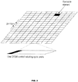
- the basic LTE physical communication resources can thus be seen as a time-frequency grid, as illustrated in the example in FIG. 2 , where each resource element corresponds to one subcarrier during one OFDM symbol interval (on a particular antenna port).
- LTE downlink transmissions are organized into radio frames of 10 ms, each radio frame including ten equally-sized subframes of 1 ms as illustrated in FIG. 3 , A subframe is divided into two slots, each of 0.5 ms time duration.
- the resource allocation in LTE is described in terms of resource blocks, where a resource block corresponds to one slot in the time domain and 12 contiguous 15 kHz subcarriers in the frequency domain. Two consecutive resource blocks (in time) represent a resource block pair and correspond to the time interval upon which transmission scheduling operates
- Transmissions in LTE are dynamically scheduled in each subframe, where the RBS transmits downlink assignments/uplink transmission grants to certain UEs via a physical downlink control channel, PDCCH.
- the PDCCH signals are transmitted in the first OFDM symbol(s) in each subframe and span (more or less) the whole system bandwidth.
- a UE that has decoded a downlink assignment earned by a PDCCH knows which resource elements in the subframe that contain data aimed for the UE.
- the UE upon receiving an uplink transmission grant, the UE knows which time/frequency resources it should transmit upon In LTE downlink, data is carried by the physical downlink shared channel, PDSCH, and in the uplink, the corresponding data channel is referred to as the physical uplink shared channel, PUSCH.
- Demodulation of transmitted data requires estimation of the radio channel which is done by using transmitted reference symbols, RSs, i.e. symbols already known by the receiver.
- RSs transmitted reference symbols
- CRSs cell-specific reference symbols
- LTE also supports UE-specific RS aimed only for assisting channel estimation for demodulation purposes.
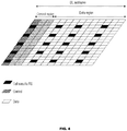
- FIG. 4 illustrates a mapping of physical control/data channels and signals onto resource elements within a downlink subframe.
- the PDCCHs occupy the first out of three possible OFDM symbols, so in this particular case the mapping of data could start at the second OFDM symbol.
- the CRS is common to all UEs in the cell, the transmission of CRS cannot be easily adapted to suit the needs of a particular UE. This is in contrast to UE-specific RS where each UE has RS of its own placed in the data region of FIG. 4 as part of the PDSCH.
- the length of the control region which can vary on subframe basis, is convoyed in the Physical Control Format indicator Channel, PCFICH.
- the PCFICH is transmitted within the control region at locations known by UEs. After a UE decodes the PCFICH, it knows the size of the control region and in which OFDM symbol die data transmission starts.
- This channel carries ACK/NACK responses to a UE to inform if the uplink data transmission in a previous subframe was successfully decoded by the base station or not
- a UE Before a UE can communicate with an LTE network it first has to find and acquire synchronization to an RBS within the network, i.e., performing cell search. Then it has to receive and decode system information needed to communicate with and operate properly within the RBS, and finally access the RBS by a random-access procedure.
- a UE In order to support mobility, a UE needs to continuously search for, synchronize to, and estimate the reception quality of both its serving RBS and neighbour RBSs. The reception quality of the neighbour RBSs, in relation to the reception quality of the serving RBS, is then evaluated in order to conclude if a handover (for UEs in connected mode) or cell re-selection (for UEs in idle mode) should be carried out.
- the handover decision is taken by the network based on measurement reports provided by the UEs. Examples of such reports are reference signal received power (RSRP) and reference signal received quality (RSRQ).
- RSRP reference signal received power
- RSRQ reference signal received quality
- the UE can for example be connected to the RBS with the strongest received power, the RBS with the best path gain, or something between the two.
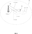
- the output power of a pico RBS 510 is in the order of 30 dBm or less, while a macro RBS 500 can have an output power of 46 dBm. Consequently, even in the proximity of the pico RBS 510, the downlink signal strength from the macro RBS 500 can be larger than that of the pico RBS 510. From a downlink perspective, it is often better to select an RBS based on downlink received power, whereas from an uplink perspective, it would be better to select an RBS based on the path loss.
- a UE it might be better, from a system perspective, for a UE to connect to the pico RBS 510 even if the macro downlink is much stronger than the pico downlink.
- ICIC across layers would be needed when UEs operate within the region of the UL border 511 and the DL border 512. This area is also referred to as the link imbalance zone
- Some form of interference coordination across the cell layers is especially important for the downlink control signalling. If this interference situation is not handled appropriately, a UE in the region between the DL and UL borders in FIG. 5 and connected to the pico RBS 510 cannot receive the downlink control signalling from the pico RBS 510.
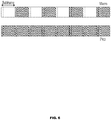
- FIG. 6 One approach for providing ICIC across layers is illustrated in FIG. 6 , where an interfering macro RBS (downlink interference towards a pico RBS) avoids scheduling unicast traffic in certain subframes implying that neither PDCCHs nor PDSCH occur in those subframes. In such way, it is possible to create low interference subframes, which can be used to protect pico users operating in the link imbalance zone, a pico user being a UE connected to the pico RBS.
- the macro RBS indicates via a backhaul interface X2 to the pico RBS which subframes it will avoid scheduling UEs within.
- the picocan then take this information into account when scheduling UEs operating within the link imbalance zone; such that these UEs are scheduled in subframes aligned with the low interference subframes at the macro layer, i.e. in interference protected subframes.
- pico cell UEs operating within the DL border can be scheduled in all subframes, i.e. in both protected and non-protected subframes.
- data transmission in different layers could also be separated in the frequency domain by ensuring that scheduling decisions in the two cell layers are non-overlapping in the frequency domain, e.g., by exchanging coordination messages between the different RBSs For control signalling, this is difficult according to the LTE specifications where control signalling spans the full bandwidth, and hence, a time-domain approach may be referable.
- RBSs e.g., transmission/reception points
- signals transmitted from or received at a point are associated with a cell-id that is different from the cell-id employed for other nearby points.
- each point transmits its own unique Signals for broadcast (e.g., Physical Broadcast Channel PBCH) and synchronisation channels (e.g., Primary Synchronisation Signal, PSS, and Secondary Synchronisation Signal SSS).
- PBCH Physical Broadcast Channel
- synchronisation channels e.g., Primary Synchronisation Signal, PSS, and Secondary Synchronisation Signal SSS.
- a point corresponds to a set of antennas covering essentially the same geographical area in a similar manner.
- a point might correspond to one of the sectors at a site, but it may also correspond to a site having one or more antennas all intending to cover a similar geographical area.
- different points represent different sites.
- Antennas correspond to different points when they are sufficiently geographically separated and/or having antenna diagrams pointing in sufficiently different directions.
- CoMP techniques introduce dependencies in the scheduling or transmission/reception among different points, in contrast to conventional cellular systems where a point from a scheduling point of view is operated more or less independently from the other points.
- FIG. 1 This typical strategy of one cell-id per point is depicted in FIG. 1 for a heterogeneous deployment where a number of low power (pico) RBSs are placed within the coverage area of a higher power macro RBS Similar principles also apply to classical macro-cellular deployments where all points have similar output power and perhaps placed in a more regular fashion than what may be the case for a heterogeneous deployment.
- macro RBS 100 is illustrated having a coverage area 101.
- the coverage area 101 has cell-id 1.
- three different low power RBSs 110, 120 and 130 are deployed Each low power RBS has a coverage area 111, 121 and 131 respectively.
- the three different coverage areas have their own specific cell-id, i.e. pico cell 111 has cell-id 2.
- pico cell 121 has cell-id 3 and pico cell 131 has cell-id 4.
- An alternative to the typical deployment strategy is to instead let all the UEs within the geographical area outlined by the coverage of the high power macro point be served with signals associated with the same cell-id. In other words, from a UE perspective, the received signals appear to be coming from a single cell. Looking at FIG. 1 , all cells 101, 111, 121 and 131 have the same cell-id, e.g. cell-id 1. Only one macro RBS 100 is shown, and other macro points would use different cell-ids (corresponding to different cells) unless they are co-located at the same site (corresponding to other sectors of the macro site).
- the same cell-id may be shared across the co-located macro-points and those pico points that correspond to the union of the coverage areas of the macro points Synchronisation, Broadcast Channel, BCH, and control channels are all transmitted from the high power point while data can be transmitted to a UE also from low power points by using shared data transmissions PDSCH relying on UE specific RS.
- Such an approach has benefits for those UEs capable oF PDSCH based on UE-specific RS, while UEs only supporting CRS for PDSCH (which is likely to at least include all LTE Release 8/9 UEs for frequency Division Duplex, FDD) must settle with the transmission from the high power point and thus will not benefit in the downlink from the deployment of extra low power points.
- the single cell-id approach is geared towards situations in which there is fast backhaul communication between the points associated to the same cell.
- An example case might be an RBS serving one or more sectors on a macro level as well as having fast fibre connections to remote radio units (RRUs) playing the role of the other points sharing the same cell-id.
- RRUs remote radio units
- Those RRUs could represent low power points with one or more antennas each.
- Another example is when all the points have a similar power class with no single point having more significance in than the others.
- the RBS handles the signals from all RRUs in a similar manner
- a shared cell approach also allows decoupling of the downlink with the uplink so that for example, path loss based reception point selection can be performed in uplink while not creating a severe interference problem for the downlink, where the UE may be served by a transmission point different from the point used in the uplink reception. Topically, this means that the UE's uplink transmissions are received by a pico point, while the UE receives downlink transmissions from the macro point
- uplink power control is performed by estimating a path loss (PL) term and combining it with various UE-specific and cell-specific power offset terms.
- the serving cell chosen as the reference serving cell and used for determining referenceSignalPower and higher layer filtered RSRP is configured by the higher layer parameter pathlossReferenceLinking .
- a problem with uplink power control is that decoupling the downlink operations from the uplink operations does not apply to the UE's open loop part of the output power setting because the UE regulates its transmit power based on the CRS's and a reference power level transmitted by the RBS.
- the open loop part of the power control may completely determine the output power, e.g., when the UE is only using open-loop power control.
- the RSRP measurement that determines transmit power will not take the pico RBSs into account, which means that the UE will transmit with a power level that causes the received power in the pico RBS to be far above what is determined by the UE-specific and/or cell-specific power offset P0.
- the network may then employ closed loop power control to steer the UE's output power to a value that it sees fit. This can be done by sending transmit power commands, TPCs, in uplink grants to the UE.
- the TPC is a two-bit instruction and can be either an absolute setting or an accumulative value. The accumulative value, which would be required to control the power over a large dynamic range, takes one of the four values [-1, 0, 1, 2] dB.
- the UE power control will be detrimental towards achieving area splitting gains. Because the macro RBS has a much higher output power than pico RBSs, UEs that could be served by a pico RBS in the uplink will too often regulate their transmit power towards the macro RBS even though the macro RBS has a much lower path gain that the pico RBS. This power output will likely create excessive interference within the cell and thereby degrade the possibility of multi-user access (e.g., SDMA) within the cell. Also, the UE power consumption will be unnecessarily high if a too high output power is used.
- multi-user access e.g., SDMA
- US2011/039569 discloses a wireless communication device and method wherein the device determines pathloss between the wireless communication device and the neighboring non-serving cell in response to an order from a serving cell, determines a maximum acceptable transmit power of the wireless communication device based on the pathloss, and limits a transmit power of the wireless communication device, based on a maximum acceptable transmit power, while the wireless communication device is connected to the serving cell.
- a base station system configured to, among other things, (a) detect whether a particular UE is not using an appropriate amount of power to transmit uplink data (e.g., the base station system may be configured to determine whether the US transmit power is too high) and (b) in response, transmit a message to the UE instructing the UE to detect a power control RS (PCRS) that is intended only for the particular UE.
- PCRS power control RS
- the PCRS is transmitted such that the power (actual or nominal) of the PCRS as received by the UE is higher than the power of the previous CRS detected by the UE, thereby leading the UE to calculate a lower PL value, which can lead to the UE lowering its output power.
- a method for controlling dynamically the power at which a communication device transmits an uplink signal includes: transmitting data to the communication device from a first radio base station (RBS) (e.g., a macro RBS such, for example, as a macro eNB); determining, at a second RBS, based on the power of a first uplink signal received at a second RBS (e.g., a pico RBS such, for example, as a pico eNB)and transmitted by the communication device, whether the transmission power of the communication device should be adjusted (e.g., decreased or increased); and in response to a determination that the transmission power of the communication device should be adjusted, selecting, at the first RBS, a reference power based on the power of the first uplink signal, transmitting from the first RBS to the communication device a message containing the selected reference power value, and transmitting from the first RBS and/or the second RBS, a communication device specific reference signal.
- RBS radio base station
- a second RBS e.
- the communication device is configured such that the communication device receives the reference signal(s), determines a measure of uplink transmission power level based on the received reference signal(s), and transmits a second uplink signal at the determined power level.
- the step of determining whether the transmission power of the communication device should be adjusted may comprise determining the power of the first uplink signal and determining whether the determined power of the first uplink signal exceeds a threshold. In other embodiments it may comprise determining the power of the first uplink signal and determining whether the determined power of the first uplink signal is lower than a threshold
- the first RBS in response to a determination that the transmission power of the communication device should be adjusted, is used to transmit the communication device specific reference signal.
- the second RBS is used to transmit the communication device specific reference signal.
- the communication device specific reference signal is transmitted by both the first RBS and the second RBS in response to a determination that the transmission power of the communication device should be adjusted.
- the communication device is configured such that the communication device combines the reference signal transmitted from the first RBS with the reference signal transmitted by the second RBS and uses the combined reference signals to determine the measure of uplink transmission power level
- a controller of the second RBS transmits a message to a controller of the first RBS in response to the determination that the transmission power of the communication device should be adjusted, and the second RBS is used to transmit the reference signal after the message is transmitted to the first RBS.
- the first RBS in response to receiving the message transmitted from the second RBS, is used to transmit to the communication device reference signal information (RSI), wherein the RSI indicates the resources that the second RBS will use to transmit the reference signal.
- RSI communication device reference signal information
- the controller of the first RBS transmits the RSI to the controller of the second RBS in response to receiving the message transmitted from the second RBS, and the second RBS is used to transmit the reference signal using the resources identified by the RSI in direct response to the controller of the second RBS receiving the RSI from the controller of the first RBS.
- the communication device specific reference signal may be a reference signal for use by a second communication device, such as a demodulation reference signal that the second communication device uses to demodulate a signal.
- a base station system for controlling dynamically the power at which a communication device transmits an uplink signal.
- the base station system comprises one or more radio base stations, RBSs, the one or more RBSs comprising a first RBS and a second RBS, and the one or more RBSs collectively comprising electronic circuitry.
- the electronic circuitry is configured to: detect, at the second RBS, a first uplink signal transmitted by the communication device; determine, at the second RBS, the power of the detected signal; use, at the second RBS, the determined power of the detected signal to determine whether the communication device should transmit a second uplink signal at a power different than the power at which the communication device transmitted the first uplink signal; and in response to determining that the communication device should transmit the second uplink signal at a different power: use, at the first RBS, the determined power of the detected signal to select a reference power; transmit, from the first RBS and/or the second RBS, to the communication device, reference signal information (RSI) identifying transmission resources and the selected reference power value, and transmit, from the first RBS and/or the second RBS, a communication device specific reference signal using the identified transmission resources.
- RSI reference signal information
- FIG. 7 illustrates an example base station system 700 in which the disclosed methods may be implemented.
- base station system 700 may be configured to (a) detect whether a UE is not using an appropriate amount of power to transmit uplink data (e.g., detect whether a UE is using too much power to transmit the uplink data) and (b) in response, transmit a power control RS (PCRS) (e.g., a UE specific PCRS) and instruct the UE to detect the power of the transmitted PCRS and use the detected power in setting its own transmit power, by.
- PCRS power control RS
- base station system 700 can dynamically cause a UE to transmit using less (or more) power by, for example, transmitting a UE specific PCRS with relatively high (or low) actual power(or reported power) than a previously transmitted RS (such as a CRS), which may or may not have been specific to the UE, or transmitting the UE specific PCRS from an RBS closer to (or farther from) the UE than the RBS that transmitted the previous RS. thereby causing the UE to calculate a lower PL (or higher PL), which can cause the UE to lower (or raise) its transmit power.
- This proposed solution is extremely flexible. It enables system 700 to change the basis of the uplink power control on a subframe time scale, or even within a subframe from one resource block to another. Another advantage is that the embodiments decouple uplink power control from the downlinkCRSs and provides a dynamic and extremely flexible way for the network to control how the UEs' open loop power control should function, something that may be of importance in future alternative deployments. Additionally, it enables the possibility to adapt power control to dynamics in traffic conditions seen by a scheduler.
- the PCRSs typically need not be sent as often as the current CRSs which are sent every subframe
- the PCRS may also be re-used time-frequency wise within the cell if they are orthogonal in the spatial domain They can even be sent on the same resources from different nodes from one subframe to the next, enabling a very fast way of controlling the uplink transmissions.
- proper area splitting gains for the uplink are enabled by controlling the transmit power of a UE towards the node that has the lowest path loss, minimizing interference both to the own cell and others Yet another advantage is the conservation of UE battery life.
- the innovation further provides the option for the network to control the trade-off between periodicity and density of power control measurements versus increased control channel overhead.
- exemplary base station system 700 includes a macro RBSs 100 (e.g., a macro eNB) and a number of pico RBSs 110, 120, and 130.
- base station system 700 may include any number of macro and/or pico RBSs.
- a controller may be associated with (e.g., connected to or part of) each RBS. More specifically, as shown, controller 102 is associated with RBS 100, controller 112 is associated with RBS 110, controller 122 is associated with RBS 120, and controller 132 is associated with RBS 130.
- RBSs 100, 110, 120 and 130 may all be associated with the same controller
- the term RBS is used broadly.
- an RBS may be an eNodeB. an RRU, or any type of transmission point (e.g., an antenna).
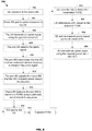
- FIG. 8 is a flow chart illustrating a process 800, according to some embodiments, for controlling dynamically the power at which a communication device (e.g., a UE, such as UE 715) transmits an uplink signal.
- a communication device e.g., a UE, such as UE 715
- Process 800 may begin in step 802, where UE 715 connects to macro RBS 100.
- UE 715 may: find and acquire synchronization to RBS 100, receive and decode system information needed to communicate with RBS 100, and access RBS 100 by a random-access procedure.
- RBS 100 may grant uplink resources to UE 715, thereby allowing UE 715 to transmit uplink data in an uplink signal.
- UE 715 transmits the uplink signal using the granted resource(s).
- the power at which UE 715 transmits the uplink signal may have been determined based on a CRS that was transmitted by macro RBS 100, as described in the background section.
- a pico RBS detects the uplink signal, determines the power of the uplink signal and compares the power of the received uplink signal against a power threshold.
- RBS 110 based on the comparison determines that UE 715 is transmitting using an undesired amount of power (e.g., too much pawer). For example, in step 801, RBS 110 may determine that the power of the received uplink signal exceeds the threshold.
- RBS 110 in response to determining that UE 715 used an undesired amount of power to transmit the uplink signal and that the transmission power of UE 715 should be adjusted, signals RBS 100 that UE 715's transmit power should be adjusted.
- controller 112 may send to controller 102 a message containing information indicating that the transmission power of UE 715 should be decreased.
- step 814 in response to learning that the transmission power of UE 715 should be adjusted (e.g., in response to receiving the message), RBS 100 instructs RBS 110 to transmit a PCRS(e.g., a UE specific PCRS).
- a PCRS e.g., a UE specific PCRS
- controller 102 of RBS 100 may transmit to controller 112 of RBS 110 a message identifying the PCRS and the particular set of downlink resources (e.g., one or more resource elements) and instructing RBS 110 to transmit the identified PCRS using the identified downlink resources.
- a message containing reference signal information is transmitted to UE 715, by, for example, RBS 100 or RBS 110.
- the message may be a layer 3 message, such as a radio resource control (RRC) message.
- RRC radio resource control
- the RSI included in the message indicates the resources (e.g., resource elements) that will be used to transmit a PCRS (see step 816).
- the message may also contain reference power information identifying a reference power (e.g., information identifying the nominal power of the PCRS or the actual power at which the PCRS will be transmitted in step 816).
- RBS 110 transmits a PCRS using the downlink resources. For example, in cases where RBS 100 transmits to RBS 110 a message identifying a PCRS and downlink resources, RBS 110 may transmit the identified PCRS using the identified resources. As another example, instead of transmitting an RS identified by RBS 100, RBS 110 may transmit a demodulation RS (DMRS) as the PCRS.
- DMRS demodulation RS
- the DMRS may be used by UE 715 to determine a PL value and subsequently the output power, and may also be used by another UE being served by RBS 110 (e.g., UE 717). In such a case, the RSI provided to UE 715 identifies the resources used to transmit the DMRS so that UE 715 can detect the DMRS.
- RBS 100 does not perform step 814 and RBS 110 does not perform step 816, rather, RBS 100, in response to learning that the transmission power of UE 715 should be decreased, transmits the PCRS using a particular set of downlink resources.
- This alternative embodiment is represented by the dotted line connecting step 812 directly with step 815, thereby by passing step 814.
- RBS 100 performs step 814 and transmits the PCRS along with RBS 110 (as well as zero or more additional RBSs). For example, in this embodiment in step 814, RBS 100 instructs not only RBS 100 to transmit the PCRS using the particular resources, but may also instruct one or more other RBS (e.g., RBS 120 and 130) to also transmit the PCRS using the same resources. In this way. UE 715 can combine the transmitted RSs in determining a measure of uplink transmission power level.
- step 818 in response to receiving the message, UE 715 uses the RSI to detect the PCRS transmitted in step 816.
- UE 715 determines a PL based on the detected PCRS. For example, in step 820, UE 715 determines the power of the received PCRS and determines the PL by determining the difference between the identified reference power and the determined power of the received PCRS. In step 822, UE 715 may adjust its transmit power based on the determined PL. In step 824, UE 715 transmits uplink data using the new power level. The uplink data transmitted in step 824 may be the same uplink data transmitted in step 806.
- UE 715 may adjust its transmit power dynamically based on a PCRS specific to the UE. That is, for example, as soon as base station system 700 detects that a UE is transmitting with too much power, system 700 can react dynamically by immediately transmitting a UE specific reference signal and instructing the UE to detect the power of the signal and adjusts its transmit power based on the actual of reported power of the UE specific reference signal
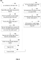
- FIG. 9 is a flow chart illustrating a process 900, according to other embodiments, for controlling dynamically the power at which UE 715 transmits an uplink signal.
- Process 900 like process 800 begins with steps 802-810, which are described above.
- step 902 in response to determining that UE 715 used an undesired amount of power to transmit its uplink data (e.g., the received power of an uplink signal transmitted from UE 715 exceeds a threshold), pico RBS 110 informs macro RBS of the UE's transmit power.
- macro RBS 100 selects an appropriate reference power value based on the UE's transmit power.
- RBS 100 may select a relatively low or high reference power.
- macro RBS 100 transmits to UE 715 a message containing the selected reference power value (the message may also contain RSI that indicates resources that will be used to transmit a PCRS specific to UE 715).
- macro RBS 100 transmits a PCRS, which may be a PCRS specifically for only UE 715.
- the power at which macro RBS transmits the PCRS may or may not be equal to the selected reference power.
- macro RBS 100 may transmit the PCRS using the same power level it used to transmit the immediately previous RS (e.g., CRS) that USE 715 used to set its uplink transmit power.
- the selected reference power value will be lower than the actual transmits power of the PCRS so that UE 715 will calculate a lower PL value, and hence, reduce its output power.
- UE 715 detects the PCRS transmitted in step 908. After step 910, process 900 continues with steps 820-824. which are described above.
- FIG. 10 illustrates a block diagram of a controller (e.g., controlled 102 or 112), according to some embodiments.
- the controller 102, 112 may include: a data processing system 1002, which may include one or more data processing devices each having one or more microprocessors and/or one or more circuits, such as an application specific integrated circuit (ASIC), Field-programmable gate arrays (FPGAs), etc; a network interface 1005 for receiving message from other controllers or network devices and transmitting messages to other controller or network devices; an interface 1004 for receiving data from and transmitting data to RBS 110; a data storage system 1006, which may include one or more computer-readable mediums, such as non-volatile storage devices and/or volatile storage devices (e.g., random access memory (RAM)).
- ASIC application specific integrated circuit
- FPGAs Field-programmable gate arrays
- a computer program product includes: computer readable program code 1043, which implements a computer program, stored on a computer readable medium 1042, such as, but not limited, to magnetic media (e.g., a hard disk), optical media (e.g., a DVD), memory devices (e.g., random access memory), etc.
- computer readable program code 1043 is configured such that, when executed by data processing system 1002, code 1043 causes the processing system 1002 to perform steps described above (e.g., steps describe above with reference to the flow chart shown in FIG. 8 and/or the flow chart shown in FIG. 9 ).
- controller 102, 112 may be configured to perform steps described above without the need for code 1043
- data processing system 1002 may consist merely of specialized hardware, such as one or more application-specific integrated circuits (ASiCs).
- ASiCs application-specific integrated circuits
- the features of the present invention described above may be implemented in hardware and/or software.
- the functional components of controller 102, 112 described above may be implemented by data processing system 1002 executing computer instructions 1043, by data processing system 1002 operating independent of any computer instructions 1043, or by any suitable combination of hardware and/or software.
Landscapes
- Engineering & Computer Science (AREA)
- Computer Networks & Wireless Communication (AREA)
- Signal Processing (AREA)
- Mobile Radio Communication Systems (AREA)
Claims (15)
- Verfahren zum dynamischen Steuern der Leistung, mit der eine Kommunikationsvorrichtung (715) ein Uplinksignal überträgt, umfassend:Übertragen von Daten zur Kommunikationsvorrichtung von einer ersten Funkbasisstation, RBS (100); undBestimmen (810), an einer zweiten RBS (110, 120, 130), aufgrund der Leistung eines ersten Uplinksignals, das an der zweiten RBS empfangen und von der Kommunikationsvorrichtung übertragen wird, ob die Übertragungsleistung der Kommunikationsvorrichtung verändert werden soll; undin Reaktion auf eine Bestimmung, dass die Übertragungsleistung der Kommunikationsvorrichtung verändert werden soll, Auswählen (904), an der ersten RBS, einer Referenzleistung aufgrund der Leistung des ersten Uplinksignals, Übertragen (815, 906) einer Nachricht, welche Referenzsignalinformationen, die Übertragungsressourcen und den ausgewählten Referenzleistungswert identifizieren, umfasst, von der ersten RBS zu der Kommunikationsvorrichtung, und Übertragen (816, 908) eines kommunikationsvorrichtungsspezifischen Referenzsignals von der ersten RBS und/oder der zweiten RBS, wobei die Kommunikationsvorrichtung so konfiguriert ist, dass die Kommunikationsvorrichtung das Referenzsignal oder Referenzsignale empfängt, ein Maß des Uplink-Übertragungsleistungspegels aufgrund des empfangenen Referenzsignals oder der Referenzsignale bestimmt, und ein zweites Uplinksignal mit dem bestimmten Leistungspegel überträgt.
- Verfahren nach Anspruch 1, wobei die erste RBS (100) in Reaktion auf eine Bestimmung, dass die Übertragungsleistung der Kommunikationsvorrichtung (715) verändert werden soll, verwendet wird, um das kommunikationsvorrichtungsspezifische Referenzsignal zu übertragen, oder die zweite RBS (110, 120, 130) verwendet wird, um das kommunikationsvorrichtungsspezifische Referenzsignal zu übertragen.
- Verfahren nach Anspruch 2, wobei die zweite RBS (110, 120, 130) verwendet wird, um das kommunikationsvorrichtungsspezifische Referenzsignal zu übertragen, und wobei eine Steuerung der zweiten RBS in Reaktion auf die Bestimmung, dass die Übertragungsleistung der Kommunikationsvorrichtung (715) verändert werden soll, eine Nachricht zu einer Steuerung der ersten RBS (100) überträgt (812) und die zweite RBS verwendet wird, um das Referenzsignal zu übertragen, nachdem die Nachricht zur ersten RBS übertragen wurde.
- Verfahren nach Anspruch 3, wobei die erste RBS (100) in Reaktion auf ein Empfangen der von der zweiten RBS (110, 120, 130) übertragenen Nachricht verwendet wird, um Referenzsignalinformationen, RSI, zu der Kommunikationsvorrichtung (715) zu übertragen (815), wobei die RSI die Ressourcen anzeigen, die die zweite RBS verwenden wird, um das Referenzsignal zu übertragen, und wobei
die Steuerung der ersten RBS (100) in Reaktion auf ein Empfangen der von der zweiten RBS (110, 120, 130) übertragenen Nachricht die RSI zur Steuerung der zweiten RBS überträgt (814), und
die zweite RBS verwendet wird, um das Referenzsignal unter Verwendung der durch die RSI identifizierten Ressourcen in direkter Reaktion darauf, dass die Steuerung der zweiten RBS die RSI von der Steuerung der ersten RBS empfängt, zu übertragen (816). - Verfahren nach Anspruch 3 oder Anspruch 4, wobei das kommunikationsvorrichtungsspezifische Referenzsignal ein Referenzsignal zur Verwendung durch eine zweite Kommunikationsvorrichtung (717) ist.
- Verfahren nach Anspruch 1, wobei das kommunikationsvorrichtungsspezifische Referenzsignal sowohl von der ersten RBS (100) als auch der zweiten RBS (110, 120, 130) in Reaktion auf eine Bestimmung, dass die Übertragungsleistung der Kommunikationsvorrichtung verändert werden soll, übertragen wird (816, 908), und wobei die Kommunikationsvorrichtung (715) so konfiguriert ist, dass die Kommunikationsvorrichtung das von der ersten RBS übertragene Referenzsignal mit dem von der zweiten RBS übertragenen Referenzsignal kombiniert und die kombinierten Referenzsignale verwendet, um das Maß des Uplink-Übertragungsleistungspegels zu bestimmen.
- Verfahren nach einem der Ansprüche 1 - 6, wobei die erste RBS (100) eine Makro-RBS ist und die zweite RBS (110, 120, 130) keine Makro-RBS ist, und
der Schritt des Bestimmens (810), ob die Übertragungsleistung der Kommunikationsvorrichtung (715) verändert werden soll, umfasst: Bestimmen der Leistung des ersten Uplinksignals und Bestimmen, ob die bestimmte Leistung des ersten Uplinksignals einen Schwellenwert übersteigt. - Verfahren nach Anspruch 1, wobei das Verfahren ferner umfasst:Erfassen (808) eines von der Kommunikationsvorrichtung übertragenen ersten Uplinksignals an der zweiten RBS (110, 120, 130);Bestimmen der Leistung des erfassten Signals an der zweiten RBS, wobei der Schritt des Bestimmens, ob die Übertragungsleistung der Kommunikationsvorrichtung verändert werden soll, ein Verwenden der bestimmten Leistung des erfassten Signals umfasst, um zu bestimmen (810), ob die Kommunikationsvorrichtung ein zweites Uplinksignal mit einer Leistung, die sich von der Leistung, mit der die Kommunikationsvorrichtung das erste Uplinksignal übertragen hat, unterscheidet, übertragen soll; undin Reaktion auf ein Bestimmen, dass die Kommunikationsvorrichtung das zweite Uplinksignal mit einer anderen Leistung übertragen soll:- Übertragen (815, 906) von Referenzsignalinformationen, RSI, die Übertragungsressourcen identifizieren, von der zweiten RBS und/oder der ersten RBS (100) zur Kommunikationsvorrichtung, wobei das kommunikationsvorrichtungsspezifisches Referenzsignal unter Verwendung der identifizierten Übertragungsressourcen übertragen wird (816, 908).
- Verfahren nach Anspruch 8, ferner umfassend:Übertragen (906) des kommunikationsvorrichtungsspezifischen Referenzsignals unter Verwendung der identifizierten Übertragungsressourcen in Reaktion auf die Bestimmung, dass die Kommunikationsvorrichtung das zweite Uplinksignal mit einer anderen Leistung übertragen soll, von der ersten RBS (100), undÜbertragen (815) des kommunikationsvorrichtungsspezifischen Referenzsignals unter Verwendung der identifizierten Übertragungsressourcen in Reaktion darauf, dass eine von der ersten RBS und der zweiten RBS bestimmt, dass die Kommunikationsvorrichtung (715) das zweite Uplinksignal mit einer anderen Leistung übertragen soll, von der zweiten RBS (110, 120, 130).
- Verfahren nach Anspruch 8, ferner umfassend:Verwenden der bestimmten Leistung des erfassten ersten Uplinksignals, um an der zweiten RBS (110, 120, 130) zu bestimmen (810), ob die Kommunikationsvorrichtung das zweite Uplinksignal mit einer anderen Leistung übertragen soll, undÜbertragen (812, 902) einer Nachricht an eine Steuerung der ersten RBS (100) in Reaktion auf ein Bestimmen (810), dass die Kommunikationsvorrichtung (715) das zweite Uplinksignal mit einer anderen Leistung übertragen soll.
- Verfahren nach Anspruch 10, ferner umfassend:Übertragen von Referenzsignalinformationen von der ersten RBS (100) zu der Kommunikationsvorrichtung (715) in Reaktion auf ein Empfangen der von der Steuerung der zweiten RBS (110, 120, 130) übertragenen Nachricht, wobei die RSI Übertragungsressourcen identifizieren.
- Basisstationsystem zum dynamischen Steuern der Leistung, mit der eine Kommunikationsvorrichtung (715) ein Uplinksignal überträgt, wobei das Basisstationsystem umfasst:eine oder mehrere Funkbasisstation(en), RBSs, (100, 110, 120, 130), wobei die eine RBS oder die mehreren RBSs eine erste RBS (100) und eine zweite RBS (110, 120, 130) umfasst bzw. umfassen, und die eine RBS oder die mehreren RBSs zusammen eine elektronische Schaltung umfasst bzw. umfassen, die konfiguriert ist, um:wobei die elektronische Schaltung ferner konfiguriert ist, um:ein erstes Uplinksignal, das von der Kommunikationsvorrichtung übertragen wird, an der zweiten RBS zu erfassen (808);die Leistung des erfassten Signals an der zweiten RBS zu bestimmen; unddie bestimmte Leistung des erfassten Signals an der zweiten RBS zu verwenden, um zu bestimmen (810), ob die Kommunikationsvorrichtung ein zweites Uplinksignal mit einer Leistung, die sich von der Leistung, mit der die Kommunikationsvorrichtung das erste Uplinksignal übertragen hat, unterscheidet, übertragen soll,in Reaktion auf ein Bestimmen, dass die Kommunikationsvorrichtung das zweite Uplinksignal mit einer anderen Leistung übertragen soll:- die bestimmte Leistung des erfassten Signals an der ersten RBS zu verwenden, um eine Referenzleistung auszuwählen;- Referenzsignalinformationen, RSI, die die Übertragungsressourcen und den ausgewählten Referenzleistungswert identifizieren, von der ersten RBS und/oder der zweiten RBS zur Kommunikationsvorrichtung zu übertragen (815, 906), und- ein kommunikationsvorrichtungsspezifisches Referenzsignal oder Signale unter Verwendung der identifizierten Übertragungsressourcen von der ersten RBS und/oder der zweiten RBS zu übertragen (816, 908).
- Basisstationsystem nach Anspruch 12, wobei:die erste RBS (100) konfiguriert ist, um das kommunikationsvorrichtungsspezifische Referenzsignal unter Verwendung der identifizierten Übertragungsressourcen in Reaktion auf die Bestimmung des Basisstationsystems, dass die Kommunikationsvorrichtung das zweite Uplinksignal mit einer anderen Leistung übertragen soll, zu übertragen, und die zweite RBS (110, 120, 130) ebenfalls konfiguriert ist, um das kommunikationsvorrichtungsspezifische Referenzsignal unter Verwendung der identifizierten Übertragungsressourcen in Reaktion auf die Bestimmung des Basisstationsystems, dass die Kommunikationsvorrichtung das zweite Uplinksignal mit einer anderen Leistung übertragen soll, zu übertragen.
- Basisstationsystem nach Anspruch 12, wobei eine Steuerung der zweiten RBS (110, 120, 130) konfiguriert ist, um:- die bestimmte Leistung des erfassten ersten Uplinksignals zu verwenden, um zu bestimmen (810), ob die Kommunikationsvorrichtung (715) das zweite Uplinksignal mit einer anderen Leistung übertragen soll, und- eine Nachricht an eine Steuerung der ersten RBS (100) in Reaktion auf ein Bestimmen, dass die Kommunikationsvorrichtung das zweite Uplinksignal mit einer anderen Leistung übertragen soll, zu übertragen;und wobei:- die Steuerung der ersten RBS konfiguriert ist, um die erste RBS zu verwenden, um Referenzsignalinformationen in Reaktion auf ein Empfangen der von der Steuerung der zweiten RBS übertragenen Nachricht zu der Kommunikationsvorrichtung zu übertragen, und- die RSI Übertragungsressourcen identifizieren;und wobei- die Steuerung der ersten RBS konfiguriert ist, um die RSI in Reaktion auf ein Empfangen der von der Steuerung der zweiten RBS empfangenen Nachricht an die zweite RBS zu übertragen; und- die zweite RBS konfiguriert ist, um die RSI unter Verwendung der identifizierten Übertragungsressourcen in Reaktion auf ein Empfangen der von der Steuerung der ersten RBS übertragenen RSI zu übertragen.
- Basisstationsystem nach einem der Ansprüche 12 - 14, wobei die erste RBS (100) eine Hochleistungs-Basisstation und die zweite RBS (110, 120, 130) eine Niedrigleistungs-Basisstation ist.
Applications Claiming Priority (3)
| Application Number | Priority Date | Filing Date | Title |
|---|---|---|---|
| US201161499542P | 2011-06-21 | 2011-06-21 | |
| US13/528,080 US9072055B2 (en) | 2011-06-21 | 2012-06-20 | Systems and methods for controlling the power at which a communication device transmits an uplink signal |
| PCT/IB2012/053154 WO2012176154A1 (en) | 2011-06-21 | 2012-06-21 | Systems and methods for controlling the power at which a communication device transmits an uplink signal |
Publications (2)
| Publication Number | Publication Date |
|---|---|
| EP2724572A1 EP2724572A1 (de) | 2014-04-30 |
| EP2724572B1 true EP2724572B1 (de) | 2017-06-14 |
Family
ID=47362343
Family Applications (1)
| Application Number | Title | Priority Date | Filing Date |
|---|---|---|---|
| EP12740688.2A Active EP2724572B1 (de) | 2011-06-21 | 2012-06-21 | Systeme und verfahren zur steuerung der uplink-signalübertragungsleistung einer kommunikationsvorrichtung |
Country Status (4)
| Country | Link |
|---|---|
| US (1) | US9072055B2 (de) |
| EP (1) | EP2724572B1 (de) |
| IN (1) | IN2014DN00287A (de) |
| WO (1) | WO2012176154A1 (de) |
Families Citing this family (35)
| Publication number | Priority date | Publication date | Assignee | Title |
|---|---|---|---|---|
| US8600393B2 (en) * | 2010-10-04 | 2013-12-03 | Samsung Electronics Co. Ltd. | Methods and apparatus for enabling interference coordination in heterogeneous networks |
| CN102917436B (zh) * | 2011-08-02 | 2017-03-15 | 上海贝尔股份有限公司 | 在共小区标识的异构网络中进行上行功率控制的方法 |
| WO2013025144A1 (en) | 2011-08-15 | 2013-02-21 | Telefonaktiebolaget Lm Ericsson (Publ) | A method and an apparatus in a user equipment for controlling transmission power of the user equipment |
| US9319990B2 (en) | 2011-10-03 | 2016-04-19 | Qualcomm Incorporated | Method and apparatus for uplink transmission power control and timing in coordinated multipoint transmission schemes |
| JP5959830B2 (ja) * | 2011-11-10 | 2016-08-02 | 株式会社Nttドコモ | 無線通信システム、無線基地局装置、ユーザ端末及び無線通信方法 |
| WO2013119167A1 (en) | 2012-02-08 | 2013-08-15 | Telefonaktiebolaget L M Ericsson (Publ) | Closed loop power control commands for srs |
| EP2813113B1 (de) | 2012-02-08 | 2018-08-29 | Telefonaktiebolaget LM Ericsson (publ) | Verfahren und vorrichtung zur uplink-leistungssteuerung in einem drahtlosen kommunikationsnetz |
| US9681397B2 (en) * | 2012-03-27 | 2017-06-13 | Qualcomm Incorporated | Format dependent power control for coordinated multipoint transmission |
| US9553680B1 (en) | 2012-04-02 | 2017-01-24 | Sprint Communications Company L.P. | Uplink interference mitigation |
| US10039116B1 (en) | 2012-04-02 | 2018-07-31 | Sprint Communications Company L.P. | Long term evolution scheduler to mitigate interference |
| EP2883395B1 (de) * | 2012-08-08 | 2017-09-27 | Nokia Technologies Oy | Verwaltung eines comp-netzwerkmesssatzes |
| EP2915381A4 (de) * | 2012-11-02 | 2016-06-01 | Intel Corp | Handhabung von signalqualitätsmessungen in einem drahtlosen kommunikationsnetz |
| CN104105180B (zh) * | 2013-04-03 | 2019-10-01 | 南京中兴软件有限责任公司 | 对干扰协同管理的方法、系统、低功率基站及rnc |
| EP2983438B1 (de) * | 2013-04-03 | 2018-10-24 | Huawei Technologies Co., Ltd. | Datenübertragungsverfahren, kommunikationsvorrichtung und kommunikationssystem |
| CN104105187A (zh) * | 2013-04-03 | 2014-10-15 | 上海贝尔股份有限公司 | 多链路连接的上行传输功率控制方法与装置 |
| US20140313953A1 (en) * | 2013-04-19 | 2014-10-23 | Qualcomm Incorporated | Adjusting measurement reports to reduce power consumption |
| WO2014194516A1 (zh) * | 2013-06-07 | 2014-12-11 | 华为技术有限公司 | 多射频拉远单元rru共小区的信号传输方法及装置 |
| WO2014198067A1 (zh) * | 2013-06-14 | 2014-12-18 | 华为技术有限公司 | 一种下行功率分配参数的通知方法及装置 |
| WO2015018033A1 (en) * | 2013-08-08 | 2015-02-12 | Mediatek Inc. | Uplink power control in adaptive tdd systems |
| CN105325034B (zh) * | 2013-10-17 | 2019-05-10 | 富士通株式会社 | 切换方法、基站和通信系统 |
| US9319988B1 (en) * | 2014-04-11 | 2016-04-19 | Sprint Spectrum L.P. | Method and system for determining initial transmission power |
| GB2525659B (en) * | 2014-05-01 | 2020-11-25 | Vodafone Ip Licensing Ltd | Arrangement for choosing transceiver nodes in a mobile telecommunications network |
| WO2015197102A1 (en) * | 2014-06-23 | 2015-12-30 | Telecom Italia S.P.A. | Fronthaul load dynamic reduction in centralized radio access networks |
| CN107231680B (zh) * | 2016-03-23 | 2021-04-30 | 中兴通讯股份有限公司 | 一种开环功率控制的方法和装置 |
| KR101993896B1 (ko) * | 2016-06-09 | 2019-06-27 | 엘지전자 주식회사 | 무선 통신 시스템에서 위상 잡음 보상 참조 신호를 송수신하기 위한 방법 및 이를 위한 장치 |
| KR102380756B1 (ko) * | 2016-08-05 | 2022-03-31 | 삼성전자 주식회사 | 무선 통신 시스템에서 위상 보상 기준 신호를 송수신하는 방법 및 장치 |
| KR102354792B1 (ko) * | 2016-12-20 | 2022-01-21 | 샤프 가부시키가이샤 | 단말 장치, 기지국 장치 및 통신 방법 |
| CN108632005B (zh) * | 2017-03-24 | 2023-12-15 | 华为技术有限公司 | 一种参考信号传输方法、装置及系统 |
| CN108989010B (zh) * | 2017-06-16 | 2019-10-22 | 华为技术有限公司 | 参考信号的传输方法和传输装置 |
| CN109391975B (zh) * | 2017-08-11 | 2022-05-17 | 中兴通讯股份有限公司 | 一种发射功率配置、随机接入功率控制方法、装置和设备 |
| WO2019029165A1 (zh) * | 2017-08-11 | 2019-02-14 | 中兴通讯股份有限公司 | 一种发射功率配置、随机接入功率控制方法、装置和设备 |
| JP6901002B2 (ja) * | 2017-09-21 | 2021-07-14 | 日本電気株式会社 | 通信制御方法、通信制御装置および通信制御プログラム |
| WO2019140665A1 (zh) | 2018-01-19 | 2019-07-25 | Oppo广东移动通信有限公司 | 功率控制的方法、终端设备和网络设备 |
| EP4070586A4 (de) * | 2020-04-10 | 2022-12-14 | ZTE Corporation | Verfahren und systeme zum verfolgen von referenzsignalpfadverlusten bei uplink-übertragungen |
| US11122525B1 (en) * | 2020-06-24 | 2021-09-14 | Charter Communications Operating, Llc | Wireless channel access and power adjust access requests |
Family Cites Families (4)
| Publication number | Priority date | Publication date | Assignee | Title |
|---|---|---|---|---|
| US7986959B2 (en) * | 2007-02-14 | 2011-07-26 | Qualcomm Incorporated | Preamble based uplink power control for LTE |
| US8938247B2 (en) * | 2009-04-23 | 2015-01-20 | Qualcomm Incorporated | Sounding reference signal for coordinated multi-point operation |
| US8600424B2 (en) * | 2009-06-19 | 2013-12-03 | Qualcomm Incorporated | Method and apparatus for managing downlink transmission power in a heterogeneous network |
| US8422956B2 (en) | 2009-08-17 | 2013-04-16 | Motorola Mobility Llc | Mitigation of uplink interference from wireless communication device connected to micro cell |
-
2012
- 2012-06-20 US US13/528,080 patent/US9072055B2/en active Active
- 2012-06-21 EP EP12740688.2A patent/EP2724572B1/de active Active
- 2012-06-21 WO PCT/IB2012/053154 patent/WO2012176154A1/en active Application Filing
- 2012-06-21 IN IN287DEN2014 patent/IN2014DN00287A/en unknown
Non-Patent Citations (1)
| Title |
|---|
| None * |
Also Published As
| Publication number | Publication date |
|---|---|
| IN2014DN00287A (de) | 2015-06-05 |
| US20120329503A1 (en) | 2012-12-27 |
| EP2724572A1 (de) | 2014-04-30 |
| WO2012176154A1 (en) | 2012-12-27 |
| US9072055B2 (en) | 2015-06-30 |
Similar Documents
| Publication | Publication Date | Title |
|---|---|---|
| EP2724572B1 (de) | Systeme und verfahren zur steuerung der uplink-signalübertragungsleistung einer kommunikationsvorrichtung | |
| EP2742747B1 (de) | Leistungssteuerung mit geschlossenem regelkreis in einem heterogenen netzwerk durch auswahl aus sets an kumulativen leistungsschrittwerten | |
| EP2724574B1 (de) | Benutzergerät und verfahren zur sendeleistungsregelung von uplink-übertragungen | |
| US9462557B2 (en) | Method and an apparatus in a user equipment for controlling transmission power of the user equipment | |
| US10136400B2 (en) | Apparatus and method for controlling transmission power in wireless communication system | |
| RU2699557C2 (ru) | Улучшения потоков управления для нелицензированного спектра lte | |
| EP2673910B1 (de) | Verteilung von zellengemeinen downlink-signalen bei einem hierarchischen heterogenen zelleneinsatz | |
| US8824383B2 (en) | Downlink scheduling in heterogeneous networks | |
| US20140126530A1 (en) | Wireless device, a network node and methods therein | |
| EP2810497B1 (de) | Leistungssteuerungsverwaltung in einer uplink-koordinierten mehrpunktübertragung | |
| KR20170141697A (ko) | 저 레이턴시 업링크 전력 제어 | |
| US11032779B2 (en) | Use of cell specific reference signals for NR open loop uplink power control |
Legal Events
| Date | Code | Title | Description |
|---|---|---|---|
| PUAI | Public reference made under article 153(3) epc to a published international application that has entered the european phase |
Free format text: ORIGINAL CODE: 0009012 |
|
| 17P | Request for examination filed |
Effective date: 20140110 |
|
| AK | Designated contracting states |
Kind code of ref document: A1 Designated state(s): AL AT BE BG CH CY CZ DE DK EE ES FI FR GB GR HR HU IE IS IT LI LT LU LV MC MK MT NL NO PL PT RO RS SE SI SK SM TR |
|
| DAX | Request for extension of the european patent (deleted) | ||
| GRAP | Despatch of communication of intention to grant a patent |
Free format text: ORIGINAL CODE: EPIDOSNIGR1 |
|
| STAA | Information on the status of an ep patent application or granted ep patent |
Free format text: STATUS: GRANT OF PATENT IS INTENDED |
|
| INTG | Intention to grant announced |
Effective date: 20170324 |
|
| GRAS | Grant fee paid |
Free format text: ORIGINAL CODE: EPIDOSNIGR3 |
|
| GRAA | (expected) grant |
Free format text: ORIGINAL CODE: 0009210 |
|
| STAA | Information on the status of an ep patent application or granted ep patent |
Free format text: STATUS: THE PATENT HAS BEEN GRANTED |
|
| AK | Designated contracting states |
Kind code of ref document: B1 Designated state(s): AL AT BE BG CH CY CZ DE DK EE ES FI FR GB GR HR HU IE IS IT LI LT LU LV MC MK MT NL NO PL PT RO RS SE SI SK SM TR |
|
| REG | Reference to a national code |
Ref country code: GB Ref legal event code: FG4D |
|
| REG | Reference to a national code |
Ref country code: CH Ref legal event code: EP Ref country code: AT Ref legal event code: REF Ref document number: 902027 Country of ref document: AT Kind code of ref document: T Effective date: 20170615 |
|
| REG | Reference to a national code |
Ref country code: IE Ref legal event code: FG4D |
|
| REG | Reference to a national code |
Ref country code: DE Ref legal event code: R096 Ref document number: 602012033423 Country of ref document: DE |
|
| REG | Reference to a national code |
Ref country code: NL Ref legal event code: FP |
|
| REG | Reference to a national code |
Ref country code: LT Ref legal event code: MG4D |
|
| PG25 | Lapsed in a contracting state [announced via postgrant information from national office to epo] |
Ref country code: LT Free format text: LAPSE BECAUSE OF FAILURE TO SUBMIT A TRANSLATION OF THE DESCRIPTION OR TO PAY THE FEE WITHIN THE PRESCRIBED TIME-LIMIT Effective date: 20170614 Ref country code: NO Free format text: LAPSE BECAUSE OF FAILURE TO SUBMIT A TRANSLATION OF THE DESCRIPTION OR TO PAY THE FEE WITHIN THE PRESCRIBED TIME-LIMIT Effective date: 20170914 Ref country code: FI Free format text: LAPSE BECAUSE OF FAILURE TO SUBMIT A TRANSLATION OF THE DESCRIPTION OR TO PAY THE FEE WITHIN THE PRESCRIBED TIME-LIMIT Effective date: 20170614 Ref country code: GR Free format text: LAPSE BECAUSE OF FAILURE TO SUBMIT A TRANSLATION OF THE DESCRIPTION OR TO PAY THE FEE WITHIN THE PRESCRIBED TIME-LIMIT Effective date: 20170915 Ref country code: HR Free format text: LAPSE BECAUSE OF FAILURE TO SUBMIT A TRANSLATION OF THE DESCRIPTION OR TO PAY THE FEE WITHIN THE PRESCRIBED TIME-LIMIT Effective date: 20170614 |
|
| REG | Reference to a national code |
Ref country code: AT Ref legal event code: MK05 Ref document number: 902027 Country of ref document: AT Kind code of ref document: T Effective date: 20170614 |
|
| PG25 | Lapsed in a contracting state [announced via postgrant information from national office to epo] |
Ref country code: LV Free format text: LAPSE BECAUSE OF FAILURE TO SUBMIT A TRANSLATION OF THE DESCRIPTION OR TO PAY THE FEE WITHIN THE PRESCRIBED TIME-LIMIT Effective date: 20170614 Ref country code: RS Free format text: LAPSE BECAUSE OF FAILURE TO SUBMIT A TRANSLATION OF THE DESCRIPTION OR TO PAY THE FEE WITHIN THE PRESCRIBED TIME-LIMIT Effective date: 20170614 Ref country code: BG Free format text: LAPSE BECAUSE OF FAILURE TO SUBMIT A TRANSLATION OF THE DESCRIPTION OR TO PAY THE FEE WITHIN THE PRESCRIBED TIME-LIMIT Effective date: 20170914 Ref country code: SE Free format text: LAPSE BECAUSE OF FAILURE TO SUBMIT A TRANSLATION OF THE DESCRIPTION OR TO PAY THE FEE WITHIN THE PRESCRIBED TIME-LIMIT Effective date: 20170614 |
|
| PG25 | Lapsed in a contracting state [announced via postgrant information from national office to epo] |
Ref country code: EE Free format text: LAPSE BECAUSE OF FAILURE TO SUBMIT A TRANSLATION OF THE DESCRIPTION OR TO PAY THE FEE WITHIN THE PRESCRIBED TIME-LIMIT Effective date: 20170614 Ref country code: CZ Free format text: LAPSE BECAUSE OF FAILURE TO SUBMIT A TRANSLATION OF THE DESCRIPTION OR TO PAY THE FEE WITHIN THE PRESCRIBED TIME-LIMIT Effective date: 20170614 Ref country code: SK Free format text: LAPSE BECAUSE OF FAILURE TO SUBMIT A TRANSLATION OF THE DESCRIPTION OR TO PAY THE FEE WITHIN THE PRESCRIBED TIME-LIMIT Effective date: 20170614 Ref country code: RO Free format text: LAPSE BECAUSE OF FAILURE TO SUBMIT A TRANSLATION OF THE DESCRIPTION OR TO PAY THE FEE WITHIN THE PRESCRIBED TIME-LIMIT Effective date: 20170614 Ref country code: AT Free format text: LAPSE BECAUSE OF FAILURE TO SUBMIT A TRANSLATION OF THE DESCRIPTION OR TO PAY THE FEE WITHIN THE PRESCRIBED TIME-LIMIT Effective date: 20170614 |
|
| REG | Reference to a national code |
Ref country code: CH Ref legal event code: PL |
|
| PG25 | Lapsed in a contracting state [announced via postgrant information from national office to epo] |
Ref country code: SM Free format text: LAPSE BECAUSE OF FAILURE TO SUBMIT A TRANSLATION OF THE DESCRIPTION OR TO PAY THE FEE WITHIN THE PRESCRIBED TIME-LIMIT Effective date: 20170614 Ref country code: IS Free format text: LAPSE BECAUSE OF FAILURE TO SUBMIT A TRANSLATION OF THE DESCRIPTION OR TO PAY THE FEE WITHIN THE PRESCRIBED TIME-LIMIT Effective date: 20171014 Ref country code: PL Free format text: LAPSE BECAUSE OF FAILURE TO SUBMIT A TRANSLATION OF THE DESCRIPTION OR TO PAY THE FEE WITHIN THE PRESCRIBED TIME-LIMIT Effective date: 20170614 Ref country code: IT Free format text: LAPSE BECAUSE OF FAILURE TO SUBMIT A TRANSLATION OF THE DESCRIPTION OR TO PAY THE FEE WITHIN THE PRESCRIBED TIME-LIMIT Effective date: 20170614 Ref country code: ES Free format text: LAPSE BECAUSE OF FAILURE TO SUBMIT A TRANSLATION OF THE DESCRIPTION OR TO PAY THE FEE WITHIN THE PRESCRIBED TIME-LIMIT Effective date: 20170614 |
|
| REG | Reference to a national code |
Ref country code: DE Ref legal event code: R097 Ref document number: 602012033423 Country of ref document: DE |
|
| REG | Reference to a national code |
Ref country code: IE Ref legal event code: MM4A |
|
| PG25 | Lapsed in a contracting state [announced via postgrant information from national office to epo] |
Ref country code: MC Free format text: LAPSE BECAUSE OF FAILURE TO SUBMIT A TRANSLATION OF THE DESCRIPTION OR TO PAY THE FEE WITHIN THE PRESCRIBED TIME-LIMIT Effective date: 20170614 |
|
| PLBE | No opposition filed within time limit |
Free format text: ORIGINAL CODE: 0009261 |
|
| STAA | Information on the status of an ep patent application or granted ep patent |
Free format text: STATUS: NO OPPOSITION FILED WITHIN TIME LIMIT |
|
| PG25 | Lapsed in a contracting state [announced via postgrant information from national office to epo] |
Ref country code: DK Free format text: LAPSE BECAUSE OF FAILURE TO SUBMIT A TRANSLATION OF THE DESCRIPTION OR TO PAY THE FEE WITHIN THE PRESCRIBED TIME-LIMIT Effective date: 20170614 Ref country code: LI Free format text: LAPSE BECAUSE OF NON-PAYMENT OF DUE FEES Effective date: 20170630 Ref country code: CH Free format text: LAPSE BECAUSE OF NON-PAYMENT OF DUE FEES Effective date: 20170630 Ref country code: LU Free format text: LAPSE BECAUSE OF NON-PAYMENT OF DUE FEES Effective date: 20170621 Ref country code: IE Free format text: LAPSE BECAUSE OF NON-PAYMENT OF DUE FEES Effective date: 20170621 |
|
| REG | Reference to a national code |
Ref country code: FR Ref legal event code: ST Effective date: 20180409 |
|
| 26N | No opposition filed |
Effective date: 20180315 |
|
| REG | Reference to a national code |
Ref country code: BE Ref legal event code: MM Effective date: 20170630 |
|
| PG25 | Lapsed in a contracting state [announced via postgrant information from national office to epo] |
Ref country code: FR Free format text: LAPSE BECAUSE OF NON-PAYMENT OF DUE FEES Effective date: 20170816 Ref country code: SI Free format text: LAPSE BECAUSE OF FAILURE TO SUBMIT A TRANSLATION OF THE DESCRIPTION OR TO PAY THE FEE WITHIN THE PRESCRIBED TIME-LIMIT Effective date: 20170614 Ref country code: BE Free format text: LAPSE BECAUSE OF NON-PAYMENT OF DUE FEES Effective date: 20170630 |
|
| PG25 | Lapsed in a contracting state [announced via postgrant information from national office to epo] |
Ref country code: MT Free format text: LAPSE BECAUSE OF NON-PAYMENT OF DUE FEES Effective date: 20170621 |
|
| PG25 | Lapsed in a contracting state [announced via postgrant information from national office to epo] |
Ref country code: HU Free format text: LAPSE BECAUSE OF FAILURE TO SUBMIT A TRANSLATION OF THE DESCRIPTION OR TO PAY THE FEE WITHIN THE PRESCRIBED TIME-LIMIT; INVALID AB INITIO Effective date: 20120621 |
|
| PG25 | Lapsed in a contracting state [announced via postgrant information from national office to epo] |
Ref country code: CY Free format text: LAPSE BECAUSE OF NON-PAYMENT OF DUE FEES Effective date: 20170614 |
|
| PG25 | Lapsed in a contracting state [announced via postgrant information from national office to epo] |
Ref country code: MK Free format text: LAPSE BECAUSE OF FAILURE TO SUBMIT A TRANSLATION OF THE DESCRIPTION OR TO PAY THE FEE WITHIN THE PRESCRIBED TIME-LIMIT Effective date: 20170614 |
|
| PG25 | Lapsed in a contracting state [announced via postgrant information from national office to epo] |
Ref country code: TR Free format text: LAPSE BECAUSE OF FAILURE TO SUBMIT A TRANSLATION OF THE DESCRIPTION OR TO PAY THE FEE WITHIN THE PRESCRIBED TIME-LIMIT Effective date: 20170614 |
|
| PG25 | Lapsed in a contracting state [announced via postgrant information from national office to epo] |
Ref country code: PT Free format text: LAPSE BECAUSE OF FAILURE TO SUBMIT A TRANSLATION OF THE DESCRIPTION OR TO PAY THE FEE WITHIN THE PRESCRIBED TIME-LIMIT Effective date: 20170614 |
|
| PG25 | Lapsed in a contracting state [announced via postgrant information from national office to epo] |
Ref country code: AL Free format text: LAPSE BECAUSE OF FAILURE TO SUBMIT A TRANSLATION OF THE DESCRIPTION OR TO PAY THE FEE WITHIN THE PRESCRIBED TIME-LIMIT Effective date: 20170614 |
|
| PGFP | Annual fee paid to national office [announced via postgrant information from national office to epo] |
Ref country code: NL Payment date: 20220626 Year of fee payment: 11 Ref country code: GB Payment date: 20220628 Year of fee payment: 11 |
|
| PGFP | Annual fee paid to national office [announced via postgrant information from national office to epo] |
Ref country code: DE Payment date: 20230626 Year of fee payment: 12 |
|
| REG | Reference to a national code |
Ref country code: NL Ref legal event code: MM Effective date: 20230701 |
|
| GBPC | Gb: european patent ceased through non-payment of renewal fee |
Effective date: 20230621 |
|
| PG25 | Lapsed in a contracting state [announced via postgrant information from national office to epo] |
Ref country code: NL Free format text: LAPSE BECAUSE OF NON-PAYMENT OF DUE FEES Effective date: 20230701 |
|
| PG25 | Lapsed in a contracting state [announced via postgrant information from national office to epo] |
Ref country code: GB Free format text: LAPSE BECAUSE OF NON-PAYMENT OF DUE FEES Effective date: 20230621 |