EP2724122B1 - Optical sensor systems and methods - Google Patents
Optical sensor systems and methods Download PDFInfo
- Publication number
- EP2724122B1 EP2724122B1 EP12725979.4A EP12725979A EP2724122B1 EP 2724122 B1 EP2724122 B1 EP 2724122B1 EP 12725979 A EP12725979 A EP 12725979A EP 2724122 B1 EP2724122 B1 EP 2724122B1
- Authority
- EP
- European Patent Office
- Prior art keywords
- photonic crystal
- sensor
- crystal sensor
- reflection spectrum
- sensed parameter
- Prior art date
- Legal status (The legal status is an assumption and is not a legal conclusion. Google has not performed a legal analysis and makes no representation as to the accuracy of the status listed.)
- Active
Links
Images


Classifications
-
- G—PHYSICS
- G01—MEASURING; TESTING
- G01D—MEASURING NOT SPECIALLY ADAPTED FOR A SPECIFIC VARIABLE; ARRANGEMENTS FOR MEASURING TWO OR MORE VARIABLES NOT COVERED IN A SINGLE OTHER SUBCLASS; TARIFF METERING APPARATUS; MEASURING OR TESTING NOT OTHERWISE PROVIDED FOR
- G01D5/00—Mechanical means for transferring the output of a sensing member; Means for converting the output of a sensing member to another variable where the form or nature of the sensing member does not constrain the means for converting; Transducers not specially adapted for a specific variable
- G01D5/26—Mechanical means for transferring the output of a sensing member; Means for converting the output of a sensing member to another variable where the form or nature of the sensing member does not constrain the means for converting; Transducers not specially adapted for a specific variable characterised by optical transfer means, i.e. using infrared, visible, or ultraviolet light
- G01D5/268—Mechanical means for transferring the output of a sensing member; Means for converting the output of a sensing member to another variable where the form or nature of the sensing member does not constrain the means for converting; Transducers not specially adapted for a specific variable characterised by optical transfer means, i.e. using infrared, visible, or ultraviolet light using optical fibres
-
- G—PHYSICS
- G01—MEASURING; TESTING
- G01D—MEASURING NOT SPECIALLY ADAPTED FOR A SPECIFIC VARIABLE; ARRANGEMENTS FOR MEASURING TWO OR MORE VARIABLES NOT COVERED IN A SINGLE OTHER SUBCLASS; TARIFF METERING APPARATUS; MEASURING OR TESTING NOT OTHERWISE PROVIDED FOR
- G01D5/00—Mechanical means for transferring the output of a sensing member; Means for converting the output of a sensing member to another variable where the form or nature of the sensing member does not constrain the means for converting; Transducers not specially adapted for a specific variable
- G01D5/26—Mechanical means for transferring the output of a sensing member; Means for converting the output of a sensing member to another variable where the form or nature of the sensing member does not constrain the means for converting; Transducers not specially adapted for a specific variable characterised by optical transfer means, i.e. using infrared, visible, or ultraviolet light
- G01D5/32—Mechanical means for transferring the output of a sensing member; Means for converting the output of a sensing member to another variable where the form or nature of the sensing member does not constrain the means for converting; Transducers not specially adapted for a specific variable characterised by optical transfer means, i.e. using infrared, visible, or ultraviolet light with attenuation or whole or partial obturation of beams of light
- G01D5/34—Mechanical means for transferring the output of a sensing member; Means for converting the output of a sensing member to another variable where the form or nature of the sensing member does not constrain the means for converting; Transducers not specially adapted for a specific variable characterised by optical transfer means, i.e. using infrared, visible, or ultraviolet light with attenuation or whole or partial obturation of beams of light the beams of light being detected by photocells
- G01D5/353—Mechanical means for transferring the output of a sensing member; Means for converting the output of a sensing member to another variable where the form or nature of the sensing member does not constrain the means for converting; Transducers not specially adapted for a specific variable characterised by optical transfer means, i.e. using infrared, visible, or ultraviolet light with attenuation or whole or partial obturation of beams of light the beams of light being detected by photocells influencing the transmission properties of an optical fibre
- G01D5/35338—Mechanical means for transferring the output of a sensing member; Means for converting the output of a sensing member to another variable where the form or nature of the sensing member does not constrain the means for converting; Transducers not specially adapted for a specific variable characterised by optical transfer means, i.e. using infrared, visible, or ultraviolet light with attenuation or whole or partial obturation of beams of light the beams of light being detected by photocells influencing the transmission properties of an optical fibre using other arrangements than interferometer arrangements
- G01D5/35354—Sensor working in reflection
-
- G—PHYSICS
- G01—MEASURING; TESTING
- G01D—MEASURING NOT SPECIALLY ADAPTED FOR A SPECIFIC VARIABLE; ARRANGEMENTS FOR MEASURING TWO OR MORE VARIABLES NOT COVERED IN A SINGLE OTHER SUBCLASS; TARIFF METERING APPARATUS; MEASURING OR TESTING NOT OTHERWISE PROVIDED FOR
- G01D5/00—Mechanical means for transferring the output of a sensing member; Means for converting the output of a sensing member to another variable where the form or nature of the sensing member does not constrain the means for converting; Transducers not specially adapted for a specific variable
- G01D5/26—Mechanical means for transferring the output of a sensing member; Means for converting the output of a sensing member to another variable where the form or nature of the sensing member does not constrain the means for converting; Transducers not specially adapted for a specific variable characterised by optical transfer means, i.e. using infrared, visible, or ultraviolet light
- G01D5/32—Mechanical means for transferring the output of a sensing member; Means for converting the output of a sensing member to another variable where the form or nature of the sensing member does not constrain the means for converting; Transducers not specially adapted for a specific variable characterised by optical transfer means, i.e. using infrared, visible, or ultraviolet light with attenuation or whole or partial obturation of beams of light
- G01D5/34—Mechanical means for transferring the output of a sensing member; Means for converting the output of a sensing member to another variable where the form or nature of the sensing member does not constrain the means for converting; Transducers not specially adapted for a specific variable characterised by optical transfer means, i.e. using infrared, visible, or ultraviolet light with attenuation or whole or partial obturation of beams of light the beams of light being detected by photocells
- G01D5/353—Mechanical means for transferring the output of a sensing member; Means for converting the output of a sensing member to another variable where the form or nature of the sensing member does not constrain the means for converting; Transducers not specially adapted for a specific variable characterised by optical transfer means, i.e. using infrared, visible, or ultraviolet light with attenuation or whole or partial obturation of beams of light the beams of light being detected by photocells influencing the transmission properties of an optical fibre
- G01D5/35383—Mechanical means for transferring the output of a sensing member; Means for converting the output of a sensing member to another variable where the form or nature of the sensing member does not constrain the means for converting; Transducers not specially adapted for a specific variable characterised by optical transfer means, i.e. using infrared, visible, or ultraviolet light with attenuation or whole or partial obturation of beams of light the beams of light being detected by photocells influencing the transmission properties of an optical fibre using multiple sensor devices using multiplexing techniques
- G01D5/35387—Mechanical means for transferring the output of a sensing member; Means for converting the output of a sensing member to another variable where the form or nature of the sensing member does not constrain the means for converting; Transducers not specially adapted for a specific variable characterised by optical transfer means, i.e. using infrared, visible, or ultraviolet light with attenuation or whole or partial obturation of beams of light the beams of light being detected by photocells influencing the transmission properties of an optical fibre using multiple sensor devices using multiplexing techniques using wavelength division multiplexing
Definitions
- the present disclosure is generally related to optical sensors.
- aircraft fuel tank sensing systems may include multiple sensors inside a fuel tank. Each sensor may be connected to a control system via a wire. Further, each sensor may be associated with a tank penetration to route wires from the sensor to the control system.
- each wire may also be routed through other aircraft structures, such as bulkheads. Providing penetrations for the wiring (in the fuel tank and in the other aircraft structures) as well as routing the wiring can be challenging both during aircraft design and in manufacturing and maintenance of the aircraft. Additionally, the wiring and sensors themselves may add considerable cost and weight to the aircraft.
- EP 1 324 099 discloses a fiber coupling device comprising fixing parts, to which the respective ends of two optical fibers and are fixed, photonic crystal, disposed inside the light path of light that propagates across the abovementioned ends, and external force application means, which applies an external force to photonic crystal.
- external force application means which applies an external force to photonic crystal.
- Optical sensors may have certain advantages over electrical sensors. For example, optical sensors are generally not sensitive to electromagnetic interference. Also, optical sensors may be relatively small as compared to certain legacy sensors. Particular optical sensor assemblies and optical sensor systems disclosed herein may be relatively inexpensive and may provide highly accurate sensing. For example, an optical sensor system may use encapsulated multimode fiber arrays with fiber tip sensors to measure temperature, pressure, or other parameters simultaneously. Such a system may be simple in configuration, flexible, highly tolerant to light source fluctuations, and inexpensive. Additionally, the system can achieve high accuracy while operating in an adverse environment. For example, disclosed optical sensors may be used in aircraft engines and fuel tanks where conditions such as heat and safety concerns may lead to difficulties in applying electrical sensing systems. Additionally, the optical sensors may be considerably smaller than electrical sensors and may use less power. Further, since the optical sensors are not sensitive to electromagnetic interference, no metallic shielding is required and considerable cost and weight savings may be achieved.
- an optical sensor assembly includes a substrate, a first photonic crystal sensor coupled to the substrate, and a second photonic crystal sensor coupled to the substrate.
- the first photonic crystal sensor is configured to reflect a first portion of incident light corresponding to a first reflection spectrum.
- a first wavelength range of the first reflection spectrum changes in response to changes in a first sensed parameter.
- the second photonic crystal sensor is configured to reflect a second portion of the incident light corresponding to a second reflection spectrum.
- a second wavelength range of the second reflection spectrum changes in response to changes in a second sensed parameter which is different from the first sensed parameter.
- the first reflection spectrum and the second reflection spectrum may be different and parameter values of the first and second sensed parameters are determinable from the first and second reflected spectrums respectively.
- an optical sensor system in a particular embodiment, includes an optical fiber and an optical sensor assembly coupled to a tip of the optical fiber.
- the optical sensor assembly includes a first photonic crystal sensor configured to exhibit a first reflection spectrum that changes responsive to a first sensed parameter and a second photonic crystal sensor configured to exhibit a second reflection spectrum that changes responsive to a second sensed parameter.
- the first reflection spectrum and the second reflection spectrum may be different.
- a method in a particular embodiment, includes applying light to a first end of an optical fiber. Light reflected by a first photonic crystal sensor coupled to a second end of the optical fiber and a second photonic crystal sensor coupled to the second end of the optical fiber is detected. The first photonic crystal sensor exhibits a first reflection spectrum that changes responsive a first sensed parameter and the second photonic crystal sensor exhibits a second reflection spectrum that changes responsive a second sensed parameter which is different from the first sensed parameter. The method also includes determining a parameter value of the first sensed parameter and the second sensed parameter based on the first and second reflected spectrums of the detected light respectively.
- Certain sensing systems utilize multiple, independently-targeted, electrical or electromagnetic sensor packages.
- separate sensors may be used for sensing pressure, temperature, acceleration, and so forth.
- each sensor may be coupled by a wire to a control system and may communicate information about a sensed parameter to the control system using electrical signals. Routing the wiring from each sensor to the control system may require structural penetrations and tank penetrations which can be a considerable design challenge.
- each structural penetration and tank penetration may introduce safety considerations to be addressed.
- each structural penetration and tank penetration has an associated installation time and cost.
- shielding that was associated with metal skins and structures is no longer available. Thus, additional compilations and costs may arise due to designing and installing shielding and isolation systems to provide shielding for wiring and sensors.
- optical technologies and optical sensors may be used to avoid some of these concerns with electrical sensor systems.
- an optical photonic crystal sensor device may be significantly smaller and lighter than a corresponding electrical sensor.
- electromagnetic interference is not a concern for optical technologies; thus, shielding and isolation concerns may be significantly reduced.
- embodiments disclosed herein enable sensing from multiple optical sensors via a single optical fiber which reduces a number of structural penetrations and tank penetrations to install multiple sensor systems into a particular area.
- Using a single optical fiber rather than multiple optical fibers or multiple electrical connections may significantly reduce installation and repair costs as well as weight of a sensor system. Accordingly, cost, reliability, installation time, and other factors may be improved by using optical sensor systems, especially optical sensor systems that include multiple photonic crystal sensors attached to a single optical fiber.
- photonic crystals may be substantially chemically and electrically inert and durable.
- photonic crystal sensors may be able to operate reliably in harsh environments, such as high temperature environments, chemically aggressive environments, and high shock or acceleration or vibration environments.
- glass optical fibers and sensing nodes of the photonic crystals may operate in extreme temperatures upwards of 900 degrees Celsius.
- lower cost polymer materials may be used for the optical fibers which may reduce costs and be lighter weight.
- An optical photonic crystal sensor includes a material that is structured to respond to changes in its environment in a manner that modifies a refractive index of the material. This change in the refractive index may result in frequency shifts in the reflection spectrum of the optical photonic crystal sensor.
- the reflection spectrum of the optical photonic crystal sensor may be responsive to a parameter sensed within the environment. For example, depending on the configuration of the optical photonic crystal sensor, the refractive index of the optical photonic crystal sensor may shift in response to temperature changes, pressure changes, vibration, acceleration, magnetic forces, etc. Accordingly, by supplying light to an optical photonic crystal sensor and detecting a reflection spectrum from the optical photonic crystal sensor an indication of values of one or more sensed parameters in the environment of the optical photonic crystal sensor may be determined.
- FIG. 1 is a block diagram of a first particular embodiment of an optical sensor system 100.
- the optical sensor system 100 may include a substrate 102 coupled to an optical fiber 110.
- the substrate 102 may include a plurality of regions 104 and 105 corresponding to separate physical locations on the substrate 102.
- a first photonic crystal sensor 106 may be coupled to or located within a first region 104 of the substrate 102 and a second photonic crystal sensor 107 may be coupled to or located within a second region 105 of the substrate 102.
- the photonic crystal sensors 106-107 are formed as part of the substrate 102.
- the substrate 102 may be etched, ablated, or otherwise processed to form the first photonic crystal sensor 106, the second photonic crystal sensor 107, or both.
- the photonic crystal sensors 106-107 are formed separately from the substrate 102. and are subsequently mechanically affixed to the substrate 102 (e.g., using an adhesive or a manufacturing process).
- the first photonic crystal sensor 106 may be configured to reflect a first portion of incident light that corresponds to a first reflection spectrum of the first photonic crystal sensor 106.
- a wavelength range of the first reflection spectrum may change in response to changes in a first sensed parameter.
- the first photonic crystal sensor 106 may have a first structure that is formed of two or more materials, such as a first material that has a first refractive index and a second material that has a second refractive index.
- the refractive index (and the reflection spectrum) of the first photonic crystal sensor 106 may change.
- the first structure of the first photonic crystal sensor 106 may include holes or other "defects" (i.e., irregularities) within the first material that are filled with the second material.
- the first material may be a solid, glass or crystalline material and the second material may be a gas, a liquid or another solid (e.g., air, an ambient gas or another material). Since the two or more materials have different refractive indices, changes in the structure of the first material may cause changes in the relative refractive index of the two materials, resulting in an overall shift in the first reflection spectrum of the first photonic crystal sensor 106.
- the second photonic crystal sensor 107 may have a second structure that is formed of two or more materials.
- the two or more materials used for the second photonic crystal sensor 107 may be the same materials as used for the first photonic crystal sensor 106, or the second photonic crystal sensor 107 may include one or more materials that are different from materials of the first photonic crystal sensor 106.
- the second photonic crystal sensor 107 may be configured to reflect a second portion of incident light that corresponds to a second reflection spectrum. A wavelength range of the second reflection spectrum may change in response to a second sensed parameter (e.g., pressure, temperature, acceleration, vibration, magnetic force, etc.).
- the first reflection spectrum of the first photonic crystal sensor 106 may be different than the second reflection spectrum of the second photonic crystal sensor 107. That is, the first photonic crystal sensor 106 and the second photonic crystal sensor 107 may reflect different wavelengths of light.
- the first sensed parameter and the second sensed parameter are different parameters.
- the optical fiber 110 may be coupled to an interrogator system 120.
- the interrogator system 120 may include one or more light sources 122 and one or more detectors 124.
- the one or more light sources 122 may provide incident light 112 that may be applied to the first photonic crystal sensor 106 and to the second photonic crystal sensor 107 via the optical fiber 110.
- the incident light 112 may be applied to the first and second photonic crystal sensors 106-107 substantially simultaneously.
- the one or more light sources 122 may simultaneously emit light in a wavelength corresponding to the first reflection spectrum of the first photonic crystal sensor 106 and light in a wavelength corresponding to the second reflection spectrum of the second photonic crystal sensor 107.
- the one or more light sources 122 may include a broad spectrum light source.
- the one or more light sources 122 may include two or more separated relatively narrow spectrum light sources, such as laser light sources.
- the one or more light sources 122, the interrogator system 120, the optical fiber 110, or the substrate 102 may include a filter (not shown) that filters out portions of the spectrum of the incident light 112 that are not used or are not needed by the photonic crystal sensors 106, 107.
- the first photonic crystal sensor 106 may reflect first reflected light 114 responsive to the first sensed parameters. Since the reflection spectrum of the first photonic crystal sensor 106 changes in response to the first sensed parameter, the first reflected light 114 may have a wavelength that is indicative of a value of the first sensed parameter.
- the second photonic crystal sensor 107 may reflect second reflected light 115. The second reflected light 115 may have a second wavelength that is indicative of a value of the second sensed parameter.
- the one or more detectors 124 may detect the first reflected light 114 and the second reflected light 115.
- the one or more detectors 124 may be coupled to one or more processors 126.
- the one or more processors 126 may receive information indicative of the wavelength of the first reflected light 114, the second reflected light 115, or both, from the one or more detectors 124.
- the processor 126 may determine a parameter value of at least one of the first sensed parameter and the second sensed parameter.
- the sensed parameters may include temperature, pressure, acceleration, vibration, magnetic force, one or more other parameters, or a combination thereof.
- the optical sensor system 100 may include more than two photonic crystal sensors, and the photonic crystal sensors of the optical sensor system 100 may be configured to sense one or more sensed parameters.
- the first photonic crystal sensor 106 is responsive to the same sensed parameter as the second photonic crystal sensor 107.
- the first photonic crystal sensor 106 is responsive to a different sensed parameter than the second photonic crystal sensor 107.
- the optical fiber 110 may include a multimode optical fiber that is adapted to transmit multiple wavelengths of light including wavelengths of the incident light 112, the first reflected light 114, the second reflected light 115, other wavelengths, or a combination thereof.
- the first reflection spectrum of the first photonic crystal sensor 106 may change in response to the first sensed parameter and in response to the second sensed parameter.
- the first photonic crystal sensor 106 is a pressure sensor.
- the reflection spectrum of the pressure sensor may change as a result of changes in physical dimensions of the structure of the first photonic crystal sensor 106 caused by changes in pressure.
- the second photonic crystal sensor 107 may be a temperature sensor.
- the reflection spectrum of the temperature sensor may change as a result of changes in physical dimensions of the structure of the second photonic crystal sensor 107 caused by changes in temperature.
- a change in temperature of the first photonic crystal sensor 106 may also change the physical dimensions of the structure of the first photonic crystal sensor 106.
- the processor 126 may have access to calibration relationships that may be used by the processor 126 to determine a value of the first sensed parameter based on the first reflected light 114 from the first photonic crystal sensor 106, the second reflected light 115 from the second photonic crystal sensor 107, and the calibration relationship that relates changes in the first reflection spectrum to changes in the first sensed parameter and changes in the second sensed parameter. For example, by comparing information about changes in the first reflection spectrum and changes in the second reflection spectrum, the processor 126 may remove a contribution of the temperature change from a determined pressure value.
- the optical sensor system 100 may be disposed within a fuel tank of an aircraft.
- light reflected by the first photonic crystal sensor 106 and the second photonic crystal sensor 107 may be used to provide information that is indicative of quantity of fuel present in the fuel tank.
- an estimate of the quantity of fuel may be determined (e.g., based on the density of the fuel or based on a calibration relationship, such as a look-up table).
- a more accurate estimate may be determined by taking multiple pressure readings (potentially at different locations within the fuel tank), by sensing temperature of the fuel as well as pressure to more accurately estimate density of the fuel, or both.
- the optical sensor system 100 may be used to avoid some of the concerns related to use of electrical sensor systems in a fuel tank.
- the optical sensor system 100 may be significantly smaller and lighter than a corresponding electrical sensor system.
- a single optical fiber e.g., the optical fiber 110
- multiple photonic crystal sensors e.g., the first photonic crystal sensor 106 and the second photonic crystal sensor 107
- the interrogator system 120 a number of structural penetrations and tank penetrations that may be used to install optical sensor system 100 may be reduced.
- using the single optical fiber 110 may reduce installation and repair costs as well as weight of the optical sensor system 100 relative to an electrical sensor system.
- cost, reliability, installation time, and other factors may be improved by using the optical sensor system 100.
- the optical sensor system 100 may also be substantially immune from electromagnetic interference. Additionally, the optical sensor system 100 may operate reliably in harsh environments, such as high temperature environments, chemically aggressive environments, and high shock or acceleration or vibration environments.
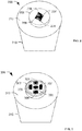
- FIG. 2 is a simplified perspective drawing of a first particular embodiment of an optical sensor assembly 200.
- the optical sensor assembly 200 includes an optical fiber 210 having a tip or end 212.
- a substrate 202 may be coupled to the end 212 of the optical fiber 210.
- the substrate 202 may include one or more photonic crystal sensors.
- the substrate 202 may divided into quadrants (or other spatial regions) with each quadrant associated with a separate optical photonic crystal sensor, such as a first photonic crystal sensor 206, a second photonic crystal sensor 207, a third photonic crystal sensor 208, and a fourth photonic crystal sensor 209.
- Each of the photonic crystal sensors 206-209 may be associated with a different reflection spectrum.
- the reflection spectrum of each of the photonic crystal sensors 206-209 may change responsive to one or more sensed parameters.
- the reflection spectra of the first photonic crystal sensor 206 and the second photonic crystal sensor 207 may each change responsive to the same sensed parameter, such as temperature.
- the reflection spectra of the third photonic crystal sensor 208 and the fourth photonic crystal sensor 209 may each change responsive to a second sensed parameter, such as pressure.
- Information descriptive of changes in the sensed parameters may be transmitted via the optical fiber 210 by way of the reflection spectra of the photonic crystal sensors 206-209.
- Information from the one of the photonic crystal sensors 206-209 may be differentiated from information from another of the photonic crystal sensors 206-209 based on the different wavelengths of the reflection spectra from the photonic crystal sensors 206-209.
- the optical sensor assembly 200 may include two or more photonic crystal sensors that together provide an indication one or more sensed parameters.
- FIG. 3 is a simplified perspective drawing of a second particular embodiment of an optical sensor assembly 300.
- the optical sensor assembly 300 includes an optical fiber 310 having a tip or end 312.
- a substrate 302 may be coupled to the end 312 of the optical fiber 310.
- Two or more photonic crystal sensors such as a first photonic crystal sensor 305, a second photonic crystal sensor 306, a third photonic crystal sensor 307, a fourth photonic crystal sensor 308, and a fifth photonic crystal sensor 309, may be coupled to the substrate 302.
- the optical sensor assembly 300 illustrates a different physical arrangement of the photonic crystal sensors 305-309 relative to the arrangement of the photonic crystal sensors 206-209 of the optical sensor assembly 200 of FIG. 2 .
- the arrangement of the photonic crystal sensors 305-309 enables the optical sensor assembly 300 to include more photonic crystal sensors than does the quadrant based arrangement of the optical sensor assembly 200 of FIG. 2 .
- an optical sensor assembly may include more than the five photonic crystal sensors 305-309 shown in FIG. 3 or fewer than five photonic crystal sensors.
- FIG. 4 is a simplified perspective drawing of a third particular embodiment of an optical sensor assembly 400.
- the optical sensor assembly 400 includes an optical fiber 410 having a tip or end 412.
- a substrate 402 may be coupled to the end 412 of the optical fiber 410.
- Two or more photonic crystal sensors such as a first photonic crystal sensor (e.g., reference photonic crystal sensor 405), a second photonic crystal sensor 406, a third photonic crystal sensor 407, a fourth photonic crystal sensor 408, and a fifth photonic crystal sensor 409, may be coupled to the substrate 402.
- the optical sensor assembly 400 illustrates a different physical arrangement of the photonic crystal sensors 405-409 relative to the arrangement of the photonic crystal sensors 206-209 of the optical sensor assembly 200 of FIG.
- the optical sensor assembly 400 includes a reference photonic crystal sensor 405 which may be at least partially isolated from an ambient environment of the optical sensor assembly 400.
- the reference photonic crystal sensor 405 may be encapsulated or covered (e.g., by a covering layer 404).
- the reference photonic crystal sensor 405 may act as a reference relative to one or more of the other photonic crystal sensors 406-409.
- the covering layer 404 may at least partially shield the reference photonic crystal sensor 405 from the ambient environment to enable differentiation of various sensed parameters.
- the reference photonic crystal sensor 405 may be subject to temperature in the ambient environment but may be at least partially shielded from pressure changes in the ambient environment.
- information from the reference photonic crystal sensor 405 may be used to isolate temperature and pressure affects sensed by one or more of the other photonic crystal sensors 406-409.
- the second photonic crystal sensor 406 may have a reflection spectrum that changes responsive to a first sensed parameter and is responsive to a second sensed parameter.
- the third photonic crystal sensor 407 may likewise have a reflection spectrum that changes responsive to the first sensed parameter and is responsive to the second sensed parameter.
- the referenced photonic crystal sensor 405 may have a reflection spectrum that changes responsive only to the second sensed parameter.
- the reference photonic crystal sensor 405 may be used to determine a parameter value of the first sensed parameter independently of the second sensed parameter, to determine a parameter value of the second sensed parameter independently of the first sensed parameter, or both, by isolating affects of one sensed parameter from affects from the other sensed parameter.
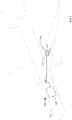
- FIG. 5 is a block diagram of a second particular embodiment of an optical sensor system 500.
- the optical sensor system 500 is disposed on a portion of an aircraft 502.
- the optical sensor system 500 may include an interrogator system 504 coupled to one or more optical fibers, such as an optical fiber 506.
- the optical fiber 506 may have a first end with a tip that is coupled to an optical sensor assembly 508.
- the optical sensor assembly 508 may disposed in a location from which sensing data is to be gathered, such as within a fuel tank 512 of the aircraft 502, within an engine of the aircraft 502, external to the aircraft 502, etc.
- the optical sensor assembly 508 may include a first photonic crystal sensor 510 and a second photonic crystal sensor 511.
- the first photonic crystal sensor 510 may be configured to exhibit a first reflection spectrum that changes responsive to a first sensed parameter.
- the second photonic crystal sensor 511 may be configured to exhibit a second reflection spectrum that changes responsive to a second sensed parameter.
- the first sensed parameter and the second sensed parameter are different.
- the first photonic crystal sensor 510 and the second photonic crystal sensor 511 may sense pressure within the aircraft fuel tank 512.
- the first photonic crystal sensor 510 may sense pressure and the second photonic crystal sensor 511 may sense temperature within the aircraft fuel tank 512.
- the reflection spectra of the first photonic crystal sensor 510 and the second photonic crystal sensor 511 may be different.
- the interrogator system 504 may identify and differentiate information from the photonic crystal sensors 510, 511 based on a wavelength of reflected light from the optical sensor assembly 508.
- the optical sensor system 500 may enable estimation of the quantity of fuel present in the fuel tank 512 based on light reflected to a light detector of the interrogator system 504.
- light associated with multiple sensors within the fuel tank 512 may be reduced as well as a number of penetrations required to enable sensors to provide sensing information to onboard systems may be reduced since multiple sensors may provide information via a single optical fiber 506.
- the optical sensor system 500 may be used to avoid some of the concerns with electrical sensor systems.
- the optical sensor system 500 may be significantly smaller and lighter than a corresponding electrical sensor system. Since a single optical fiber (e.g., the optical fiber 506) can be used to connect multiple photonic crystal sensors (e.g., the first photonic crystal sensor 510 and the second photonic crystal sensor 511) to the interrogator system 504, a number of structural penetrations and tank penetrations to install optical sensor system 500 may be reduced. Additionally, using the single optical fiber 506 may reduce installation and repair costs as well as weight of the optical sensor system 500 relative to an electrical sensor system. Thus, cost, reliability, installation time, and other factors may be improved by using the optical sensor system 500.
- the optical sensor system 500 may also be substantially immune from electromagnetic interference. Additionally, the optical sensor system 500 may operate reliably in harsh environments, such as high temperature environments, chemically aggressive environments, and high shock or acceleration or vibration environments.
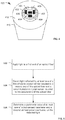
- FIG. 6 is flow chart of a particular embodiment of a method of determining a parameter value using an optical sensor system.
- the method may include, at 602, applying light to a first end of an optical fiber.
- one or more light sources of an interrogator system such the one or more light sources 122 of the interrogator system 120 of FIG. 1 , may apply light having one or more particular wavelengths to the optical fiber 110 as incident light 112.
- light may be detected, at 604.
- the detected light may be reflected by a first photonic crystal sensor coupled to a second end of the optical fiber, by a second photonic crystal sensor coupled to the second end of the optical fiber, or by both the first photonic crystal sensor and the second photonic crystal sensor.
- more than two photonic crystal sensors may be coupled to the second end of the optical fiber, such as the four photonic crystal sensors 206-209 of FIG. 2 , the five photonic crystal sensors 305-309 of FIG. 3 , or the four photonic crystal sensors 406-409 and the reference photonic crystal sensor 405 of FIG. 4 .
- the detected light may be reflected from more than two photonic crystal sensors.
- the first photonic crystal sensor may be configured to exhibit a first reflection spectrum that changes responsive to a first sensed parameter.
- the second photonic crystal sensor may be configured to exhibit a second reflection spectrum that changes responsive to a second sensed parameter.
- the first sensed parameter and the second sensed parameter are different.
- a wavelength of the first reflection spectrum and a wavelength of the second reflection spectrum may be different.
- the method may also include, at 606, determining a parameter value of at least one of the first sensed parameter and the second sensed parameter based on the detected light.
- the parameter value may be determined based on light reflected by the first photonic crystal sensor, based on light reflected by the second photonic crystal sensor, or based on both.
- the first photonic crystal sensor may exhibit a change responsive to the first sensed parameter and in responsive to the second sensed parameter.
- Light reflected by the second photonic crystal sensor may be used to determine a value of the first sensed parameter by providing information about an affect of the second sensed parameter on the first photonic crystal sensor.
- the system may include a third sensor.
- the third sensor may be another photonic crystal sensor, such as the reference photonic crystal system 405 of FIG. 4 , or may be another type of sensor (such as a non-optical sensor, e.g., an electrical sensor).
- the third sensor may provide information about the first sensed parameter, the second sensed parameter, or both.
- the parameter value may be determined based on information from the third sensor and based on light reflected by the first photonic crystal sensor.
- light reflected by the second photonic crystal sensor may be used in determining the parameter value.
- the first reflection spectrum of the first photonic crystal sensor does not change significantly responsive to changes in the second sensed parameter.
- the first photonic crystal sensor may be a reference sensor that is physically or mechanically isolated for affects of the second sensed parameter.
- the first reflection spectrum may be independent of the changes in the second sensed parameter.
- FIG. 7 is a block diagram of a general purpose computer system 700 operable to perform computer-implemented methods or to process computer-executable instructions to process data from one or more sensors, such as the photonic crystal sensors 106-107 of FIG. 1 , the photonic crystal sensors 206-209 of FIG. 2 , the photonic crystal sensors 305-309 of FIG. 3 , the photonic crystal sensors 406-409 of FIG. 4 , the reference sensor 405 of FIG. 4 , the photonic crystal sensors 510-511 of FIG. 5 , other sensors, or any combination thereof.
- the computer system 700 may be include or be included within the interrogator system 120 of FIG. 1 or the interrogator system 504 of FIG. 5 .
- a computing device 710 of the computing system 700 may include at least one processor 720.
- the processor 720 may be configured to execute instructions to implement a method of determining a parameter value using an optical sensor system, such as the method described with reference to FIG. 6 .
- the processor 720 may communicate with a system memory 730, one or more storage devices 740, and one or more input/output devices 770, via input/output interfaces 750.
- the system memory 730 may include volatile memory devices, such as random access memory (RAM) devices, and nonvolatile memory devices, such as read-only memory (ROM), programmable read-only memory, and flash memory.
- RAM random access memory
- ROM read-only memory
- flash memory nonvolatile memory devices
- the system memory 730 may include an operating system 732, which may include a basic input/output system (BIOS) for booting the computing device 710 as well as a full operating system to enable the computing device 710 to interact with users, other programs, and other devices.
- BIOS basic input/output system
- the system memory 730 may also include one or more application programs 734.
- the processor 720 also may communicate with one or more storage devices 740.
- the storage devices 740 may include nonvolatile storage devices, such as magnetic disks, optical disks, or flash memory devices. In an alternative embodiment, the storage devices 740 may be configured to store the operating system 732, the applications 734, the program data 736, or any combination thereof.
- the processor 720 may communicate with the one or more communication interfaces 760 to enable the computing device 710 to communicate with other computing systems 780.
- the storage devices 740 may store information that is used by the processor to determine a parameter value using an optical sensor system.
- the storage devices 740 may include a calibration relationship that relates changes in one or more reflection spectra to changes in sensed parameters.
- an optical sensor system 100, 500 including an optical fiber 110, 510, and an optical sensor assembly 200, 300, 400, 508 coupled to a tip of the optical fiber 110, 210, 310, 410, 506.
- the optical sensor assembly 200, 300, 400, 508 may include a first photonic crystal sensor 106 configured to exhibit a first reflection spectrum that changes responsive to a first sensed parameter, and a second photonic crystal sensor 107 configured to exhibit a second reflection spectrum that changes responsive to a second sensed parameter, wherein the first reflection spectrum and the second reflection spectrum are different.
- the optical fiber 110, 210, 310, 410, 506 is a multimode optical fiber.
- a light source may be coupled to the optical fiber, wherein the light source provides light to the optical sensor assembly 200, 300, 400, 508 via the optical fiber 10, 210, 310, 410, 506 and wherein at least a portion of the light provided by the light source 122 has a wavelength within at least one of the first reflection spectrum and the second reflection spectrum.
- a light detector 124 may be coupled to the optical fiber 110, 210, 310, 410, 506 and configured to detect light reflected by at least one of the first photonic crystal sensor 106 and the second photonic crystal sensor 107.
- a processor 126, 720 may be coupled to the light detector 124 and configured to determine a value of the first sensed parameter and a value of the second sensed parameter based on the light detected by the light detector 124.
- the first reflection spectrum of the first photonic crystal sensor 106 further changes in response to changes in the second sensed parameter
- the optical sensor system 100, 500 further comprises a processor 126, 720 to determine a value of the first sensed parameter based on light reflected by the first photonic crystal sensor 106, light reflected by the second photonic crystal sensor 107 and a calibration relationship that relates changes in the first reflection spectrum to changes in the first sensed parameter and changes in the second sensed parameter.
- the optical sensor assembly 200, 300, 400, 508 may be disposed within a fuel tank 512 of an aircraft and is configured to reflect light to a light detector 124 onboard the aircraft to estimate a quantity of fuel present in the fuel tank 512.
Landscapes
- Physics & Mathematics (AREA)
- General Physics & Mathematics (AREA)
- Measuring Fluid Pressure (AREA)
- Testing Or Calibration Of Command Recording Devices (AREA)
- Optical Transform (AREA)
- Photometry And Measurement Of Optical Pulse Characteristics (AREA)
- Radiation Pyrometers (AREA)
- Investigating Or Analysing Materials By Optical Means (AREA)
Applications Claiming Priority (2)
| Application Number | Priority Date | Filing Date | Title |
|---|---|---|---|
| US13/149,369 US20120325001A1 (en) | 2011-06-27 | 2011-06-27 | Optical sensor systems and methods |
| PCT/US2012/039218 WO2013002921A1 (en) | 2011-06-27 | 2012-05-23 | Optical sensor systems and methods |
Publications (2)
| Publication Number | Publication Date |
|---|---|
| EP2724122A1 EP2724122A1 (en) | 2014-04-30 |
| EP2724122B1 true EP2724122B1 (en) | 2019-04-17 |
Family
ID=46208830
Family Applications (1)
| Application Number | Title | Priority Date | Filing Date |
|---|---|---|---|
| EP12725979.4A Active EP2724122B1 (en) | 2011-06-27 | 2012-05-23 | Optical sensor systems and methods |
Country Status (6)
Families Citing this family (5)
| Publication number | Priority date | Publication date | Assignee | Title |
|---|---|---|---|---|
| CA2921227C (en) * | 2013-09-25 | 2017-05-09 | Institut National D'optique | All-optical system responsive to motion and optical module for use in the same |
| US9534969B1 (en) * | 2015-11-24 | 2017-01-03 | The Boeing Company | System and method for tactile sensing using thin film optical sensing networks |
| US11126065B2 (en) * | 2016-06-09 | 2021-09-21 | The Boeing Company | Photonic crystals logic devices |
| US10481041B2 (en) * | 2017-05-23 | 2019-11-19 | Fluke Corporation | Measuring optical array polarity, power, and loss using a position sensing detector and photodetector-equipped optical testing device |
| CN112949340A (zh) * | 2021-03-31 | 2021-06-11 | 上汽通用五菱汽车股份有限公司 | 一种基于光电传感器的自动扫码方法及系统 |
Citations (1)
| Publication number | Priority date | Publication date | Assignee | Title |
|---|---|---|---|---|
| WO2012024043A1 (en) * | 2010-08-18 | 2012-02-23 | The Boeing Company | Magnetically actuated photonic crystal sensor |
Family Cites Families (18)
| Publication number | Priority date | Publication date | Assignee | Title |
|---|---|---|---|---|
| US4243298A (en) * | 1978-10-06 | 1981-01-06 | International Telephone And Telegraph Corporation | High-strength optical preforms and fibers with thin, high-compression outer layers |
| JP3519333B2 (ja) * | 2000-02-10 | 2004-04-12 | エヌ・ティ・ティ・アドバンステクノロジ株式会社 | 光ファイバセンサ |
| JP2002098916A (ja) * | 2000-09-26 | 2002-04-05 | Hamamatsu Photonics Kk | 光学装置 |
| JP4619507B2 (ja) * | 2000-09-26 | 2011-01-26 | 浜松ホトニクス株式会社 | 光ファイバ結合装置、波長可変器、圧力センサ、加速度センサ及び光学装置 |
| JP4511857B2 (ja) * | 2004-03-24 | 2010-07-28 | 国立大学法人京都大学 | フォトニック結晶を応用したセンサおよび検出対象物質の検出方法 |
| US7781724B2 (en) * | 2004-07-16 | 2010-08-24 | Luna Innovations Incorporated | Fiber optic position and shape sensing device and method relating thereto |
| US7787110B2 (en) * | 2004-10-16 | 2010-08-31 | Aprilis, Inc. | Diffractive imaging system and method for the reading and analysis of skin topology |
| US7613367B2 (en) * | 2005-03-02 | 2009-11-03 | Ramot At Tel-Aviv University Ltd. | Optical sensor and modulator |
| US7289690B2 (en) * | 2005-04-15 | 2007-10-30 | Hewlett-Packard Development Company, L.P. | Photonic crystal device for fluid sensing |
| US9671301B2 (en) * | 2006-09-29 | 2017-06-06 | Wake Forest University Health Sciences | Small-scale pressure sensors |
| EP2434319B1 (en) * | 2007-01-09 | 2013-12-18 | The Board of Trustees of The Leland Stanford Junior University | Method of fabricating an optical structure on an optical fiber |
| WO2008123927A1 (en) * | 2007-04-05 | 2008-10-16 | The Board Of Trustees Of The University Of Illinois | Biosensors with porous dielectric surface for fluorescence enhancement and methods of manufacture |
| CN100588914C (zh) * | 2007-10-18 | 2010-02-10 | 西北工业大学 | 一种基于包层导光的光子晶体光纤传感装置 |
| US8282882B2 (en) * | 2010-08-23 | 2012-10-09 | Swapnajit Chakravarty | Photonic crystal slot waveguide miniature on-chip absorption spectrometer |
| US9482927B2 (en) * | 2009-10-26 | 2016-11-01 | The Boeing Company | Optical sensor interrogation system |
| US8208767B2 (en) * | 2009-11-10 | 2012-06-26 | Baker Hughes Incorporated | Sensor array configuration for extending useful sensing length of a swept-wavelength interferometry based system |
| CA3090851C (en) * | 2010-03-15 | 2023-03-07 | The Board Of Trustees Of The Leland Stanford Junior University | Optical-fiber-compatible acoustic sensor |
| TWM391136U (en) * | 2010-06-02 | 2010-10-21 | Pixart Imaging Inc | Sensor and its image sensing system |
-
2011
- 2011-06-27 US US13/149,369 patent/US20120325001A1/en not_active Abandoned
-
2012
- 2012-05-23 JP JP2014518566A patent/JP6026526B2/ja active Active
- 2012-05-23 WO PCT/US2012/039218 patent/WO2013002921A1/en unknown
- 2012-05-23 CN CN201280030514.0A patent/CN103635781B/zh active Active
- 2012-05-23 RU RU2014100990A patent/RU2618478C2/ru active
- 2012-05-23 EP EP12725979.4A patent/EP2724122B1/en active Active
Patent Citations (1)
| Publication number | Priority date | Publication date | Assignee | Title |
|---|---|---|---|---|
| WO2012024043A1 (en) * | 2010-08-18 | 2012-02-23 | The Boeing Company | Magnetically actuated photonic crystal sensor |
Also Published As
| Publication number | Publication date |
|---|---|
| US20120325001A1 (en) | 2012-12-27 |
| CN103635781B (zh) | 2016-06-01 |
| RU2014100990A (ru) | 2015-08-10 |
| CN103635781A (zh) | 2014-03-12 |
| JP2014521066A (ja) | 2014-08-25 |
| WO2013002921A1 (en) | 2013-01-03 |
| JP6026526B2 (ja) | 2016-11-16 |
| EP2724122A1 (en) | 2014-04-30 |
| RU2618478C2 (ru) | 2017-05-03 |
Similar Documents
| Publication | Publication Date | Title |
|---|---|---|
| EP2724122B1 (en) | Optical sensor systems and methods | |
| CN105865578B (zh) | 具有光子膜的多功能纤维光学燃油传感器系统 | |
| EP3161439B1 (en) | Optical fibre sensor system for detecting temperature changes in an aircraft | |
| JP5965744B2 (ja) | 光ファイバセンサのための方法およびシステム | |
| CA2903083C (en) | Proximity sensor | |
| JP6762466B2 (ja) | 圧力センサおよび1つ以上の圧力センサを備えたセンサシステム | |
| EP2029991B1 (en) | Multi-core optical fiber pressure sensor | |
| CN101886937A (zh) | 光纤布拉格光栅传感系统 | |
| NO343963B1 (no) | Optisk fiber i borehull i undergrunnen og optisk interrogator for undersøkelser med tidsproporsjonal amplitudemodulasjon og frekvensområde reflektometri | |
| CN110892148B (zh) | 从监测和控制风力涡轮机中选择的至少一者的组件及方法 | |
| US9952081B2 (en) | System and method for measuring liquid levels having a fiber with a strain layer around a Bragg grating | |
| EP2604991B1 (en) | Liquid detector and liquid identifying system | |
| EP3961163B1 (en) | Fluid quantity sensor system | |
| Nosseir et al. | Composite structures with embedded fiber optic sensors: A smart propellant tank for future spacecraft applications | |
| KR101474068B1 (ko) | 광섬유 브래그 격자를 이용한 원전 환경 모니터링 시스템 | |
| EP3967996B1 (en) | Fiber optic load sensors and systems therefor | |
| US9512715B2 (en) | Systems and methods for pressure and temperature measurement | |
| KR20170075920A (ko) | Fbg센서를 이용한 측정방법 | |
| JP6406750B2 (ja) | 光ファイバ式計測方法及び光ファイバ式計測装置 | |
| EP3120125B1 (en) | Optical fibre pressure sensor comprising in-core cavity and grating | |
| KR101185508B1 (ko) | 광섬유 센서의 온도 보상 방법 | |
| Umarov et al. | Application of fiber optic sensors in aircraft fuel management system | |
| KR101148863B1 (ko) | 광섬유 가속도 센서의 온도 보상 방법 및 광섬유 가속도 센서 | |
| KR20230120604A (ko) | 광학 파브리-페로 기반 액체 레벨 센서 | |
| Labianca | Experimental analysis on UAV systems monitoring through optical fiber based sensors |
Legal Events
| Date | Code | Title | Description |
|---|---|---|---|
| PUAI | Public reference made under article 153(3) epc to a published international application that has entered the european phase |
Free format text: ORIGINAL CODE: 0009012 |
|
| 17P | Request for examination filed |
Effective date: 20131206 |
|
| AK | Designated contracting states |
Kind code of ref document: A1 Designated state(s): AL AT BE BG CH CY CZ DE DK EE ES FI FR GB GR HR HU IE IS IT LI LT LU LV MC MK MT NL NO PL PT RO RS SE SI SK SM TR |
|
| DAX | Request for extension of the european patent (deleted) | ||
| STAA | Information on the status of an ep patent application or granted ep patent |
Free format text: STATUS: EXAMINATION IS IN PROGRESS |
|
| 17Q | First examination report despatched |
Effective date: 20171123 |
|
| GRAP | Despatch of communication of intention to grant a patent |
Free format text: ORIGINAL CODE: EPIDOSNIGR1 |
|
| STAA | Information on the status of an ep patent application or granted ep patent |
Free format text: STATUS: GRANT OF PATENT IS INTENDED |
|
| INTG | Intention to grant announced |
Effective date: 20181109 |
|
| GRAS | Grant fee paid |
Free format text: ORIGINAL CODE: EPIDOSNIGR3 |
|
| GRAA | (expected) grant |
Free format text: ORIGINAL CODE: 0009210 |
|
| STAA | Information on the status of an ep patent application or granted ep patent |
Free format text: STATUS: THE PATENT HAS BEEN GRANTED |
|
| AK | Designated contracting states |
Kind code of ref document: B1 Designated state(s): AL AT BE BG CH CY CZ DE DK EE ES FI FR GB GR HR HU IE IS IT LI LT LU LV MC MK MT NL NO PL PT RO RS SE SI SK SM TR |
|
| REG | Reference to a national code |
Ref country code: GB Ref legal event code: FG4D |
|
| REG | Reference to a national code |
Ref country code: CH Ref legal event code: EP |
|
| REG | Reference to a national code |
Ref country code: DE Ref legal event code: R096 Ref document number: 602012059071 Country of ref document: DE |
|
| REG | Reference to a national code |
Ref country code: AT Ref legal event code: REF Ref document number: 1122051 Country of ref document: AT Kind code of ref document: T Effective date: 20190515 Ref country code: IE Ref legal event code: FG4D |
|
| REG | Reference to a national code |
Ref country code: NL Ref legal event code: MP Effective date: 20190417 |
|
| REG | Reference to a national code |
Ref country code: LT Ref legal event code: MG4D |
|
| PG25 | Lapsed in a contracting state [announced via postgrant information from national office to epo] |
Ref country code: NL Free format text: LAPSE BECAUSE OF FAILURE TO SUBMIT A TRANSLATION OF THE DESCRIPTION OR TO PAY THE FEE WITHIN THE PRESCRIBED TIME-LIMIT Effective date: 20190417 |
|
| PG25 | Lapsed in a contracting state [announced via postgrant information from national office to epo] |
Ref country code: FI Free format text: LAPSE BECAUSE OF FAILURE TO SUBMIT A TRANSLATION OF THE DESCRIPTION OR TO PAY THE FEE WITHIN THE PRESCRIBED TIME-LIMIT Effective date: 20190417 Ref country code: LT Free format text: LAPSE BECAUSE OF FAILURE TO SUBMIT A TRANSLATION OF THE DESCRIPTION OR TO PAY THE FEE WITHIN THE PRESCRIBED TIME-LIMIT Effective date: 20190417 Ref country code: NO Free format text: LAPSE BECAUSE OF FAILURE TO SUBMIT A TRANSLATION OF THE DESCRIPTION OR TO PAY THE FEE WITHIN THE PRESCRIBED TIME-LIMIT Effective date: 20190717 Ref country code: HR Free format text: LAPSE BECAUSE OF FAILURE TO SUBMIT A TRANSLATION OF THE DESCRIPTION OR TO PAY THE FEE WITHIN THE PRESCRIBED TIME-LIMIT Effective date: 20190417 Ref country code: SE Free format text: LAPSE BECAUSE OF FAILURE TO SUBMIT A TRANSLATION OF THE DESCRIPTION OR TO PAY THE FEE WITHIN THE PRESCRIBED TIME-LIMIT Effective date: 20190417 Ref country code: PT Free format text: LAPSE BECAUSE OF FAILURE TO SUBMIT A TRANSLATION OF THE DESCRIPTION OR TO PAY THE FEE WITHIN THE PRESCRIBED TIME-LIMIT Effective date: 20190817 Ref country code: AL Free format text: LAPSE BECAUSE OF FAILURE TO SUBMIT A TRANSLATION OF THE DESCRIPTION OR TO PAY THE FEE WITHIN THE PRESCRIBED TIME-LIMIT Effective date: 20190417 Ref country code: ES Free format text: LAPSE BECAUSE OF FAILURE TO SUBMIT A TRANSLATION OF THE DESCRIPTION OR TO PAY THE FEE WITHIN THE PRESCRIBED TIME-LIMIT Effective date: 20190417 |
|
| PG25 | Lapsed in a contracting state [announced via postgrant information from national office to epo] |
Ref country code: LV Free format text: LAPSE BECAUSE OF FAILURE TO SUBMIT A TRANSLATION OF THE DESCRIPTION OR TO PAY THE FEE WITHIN THE PRESCRIBED TIME-LIMIT Effective date: 20190417 Ref country code: BG Free format text: LAPSE BECAUSE OF FAILURE TO SUBMIT A TRANSLATION OF THE DESCRIPTION OR TO PAY THE FEE WITHIN THE PRESCRIBED TIME-LIMIT Effective date: 20190717 Ref country code: RS Free format text: LAPSE BECAUSE OF FAILURE TO SUBMIT A TRANSLATION OF THE DESCRIPTION OR TO PAY THE FEE WITHIN THE PRESCRIBED TIME-LIMIT Effective date: 20190417 Ref country code: PL Free format text: LAPSE BECAUSE OF FAILURE TO SUBMIT A TRANSLATION OF THE DESCRIPTION OR TO PAY THE FEE WITHIN THE PRESCRIBED TIME-LIMIT Effective date: 20190417 Ref country code: GR Free format text: LAPSE BECAUSE OF FAILURE TO SUBMIT A TRANSLATION OF THE DESCRIPTION OR TO PAY THE FEE WITHIN THE PRESCRIBED TIME-LIMIT Effective date: 20190718 |
|
| REG | Reference to a national code |
Ref country code: AT Ref legal event code: MK05 Ref document number: 1122051 Country of ref document: AT Kind code of ref document: T Effective date: 20190417 |
|
| REG | Reference to a national code |
Ref country code: CH Ref legal event code: PL |
|
| PG25 | Lapsed in a contracting state [announced via postgrant information from national office to epo] |
Ref country code: IS Free format text: LAPSE BECAUSE OF FAILURE TO SUBMIT A TRANSLATION OF THE DESCRIPTION OR TO PAY THE FEE WITHIN THE PRESCRIBED TIME-LIMIT Effective date: 20190817 |
|
| REG | Reference to a national code |
Ref country code: DE Ref legal event code: R097 Ref document number: 602012059071 Country of ref document: DE |
|
| PG25 | Lapsed in a contracting state [announced via postgrant information from national office to epo] |
Ref country code: CZ Free format text: LAPSE BECAUSE OF FAILURE TO SUBMIT A TRANSLATION OF THE DESCRIPTION OR TO PAY THE FEE WITHIN THE PRESCRIBED TIME-LIMIT Effective date: 20190417 Ref country code: MC Free format text: LAPSE BECAUSE OF FAILURE TO SUBMIT A TRANSLATION OF THE DESCRIPTION OR TO PAY THE FEE WITHIN THE PRESCRIBED TIME-LIMIT Effective date: 20190417 Ref country code: SK Free format text: LAPSE BECAUSE OF FAILURE TO SUBMIT A TRANSLATION OF THE DESCRIPTION OR TO PAY THE FEE WITHIN THE PRESCRIBED TIME-LIMIT Effective date: 20190417 Ref country code: AT Free format text: LAPSE BECAUSE OF FAILURE TO SUBMIT A TRANSLATION OF THE DESCRIPTION OR TO PAY THE FEE WITHIN THE PRESCRIBED TIME-LIMIT Effective date: 20190417 Ref country code: DK Free format text: LAPSE BECAUSE OF FAILURE TO SUBMIT A TRANSLATION OF THE DESCRIPTION OR TO PAY THE FEE WITHIN THE PRESCRIBED TIME-LIMIT Effective date: 20190417 Ref country code: LI Free format text: LAPSE BECAUSE OF NON-PAYMENT OF DUE FEES Effective date: 20190531 Ref country code: EE Free format text: LAPSE BECAUSE OF FAILURE TO SUBMIT A TRANSLATION OF THE DESCRIPTION OR TO PAY THE FEE WITHIN THE PRESCRIBED TIME-LIMIT Effective date: 20190417 Ref country code: CH Free format text: LAPSE BECAUSE OF NON-PAYMENT OF DUE FEES Effective date: 20190531 Ref country code: RO Free format text: LAPSE BECAUSE OF FAILURE TO SUBMIT A TRANSLATION OF THE DESCRIPTION OR TO PAY THE FEE WITHIN THE PRESCRIBED TIME-LIMIT Effective date: 20190417 |
|
| REG | Reference to a national code |
Ref country code: BE Ref legal event code: MM Effective date: 20190531 |
|
| PLBE | No opposition filed within time limit |
Free format text: ORIGINAL CODE: 0009261 |
|
| STAA | Information on the status of an ep patent application or granted ep patent |
Free format text: STATUS: NO OPPOSITION FILED WITHIN TIME LIMIT |
|
| PG25 | Lapsed in a contracting state [announced via postgrant information from national office to epo] |
Ref country code: IT Free format text: LAPSE BECAUSE OF FAILURE TO SUBMIT A TRANSLATION OF THE DESCRIPTION OR TO PAY THE FEE WITHIN THE PRESCRIBED TIME-LIMIT Effective date: 20190417 Ref country code: SM Free format text: LAPSE BECAUSE OF FAILURE TO SUBMIT A TRANSLATION OF THE DESCRIPTION OR TO PAY THE FEE WITHIN THE PRESCRIBED TIME-LIMIT Effective date: 20190417 Ref country code: LU Free format text: LAPSE BECAUSE OF NON-PAYMENT OF DUE FEES Effective date: 20190523 |
|
| 26N | No opposition filed |
Effective date: 20200120 |
|
| PG25 | Lapsed in a contracting state [announced via postgrant information from national office to epo] |
Ref country code: TR Free format text: LAPSE BECAUSE OF FAILURE TO SUBMIT A TRANSLATION OF THE DESCRIPTION OR TO PAY THE FEE WITHIN THE PRESCRIBED TIME-LIMIT Effective date: 20190417 |
|
| PG25 | Lapsed in a contracting state [announced via postgrant information from national office to epo] |
Ref country code: IE Free format text: LAPSE BECAUSE OF NON-PAYMENT OF DUE FEES Effective date: 20190523 |
|
| PG25 | Lapsed in a contracting state [announced via postgrant information from national office to epo] |
Ref country code: BE Free format text: LAPSE BECAUSE OF NON-PAYMENT OF DUE FEES Effective date: 20190531 Ref country code: SI Free format text: LAPSE BECAUSE OF FAILURE TO SUBMIT A TRANSLATION OF THE DESCRIPTION OR TO PAY THE FEE WITHIN THE PRESCRIBED TIME-LIMIT Effective date: 20190417 |
|
| PG25 | Lapsed in a contracting state [announced via postgrant information from national office to epo] |
Ref country code: CY Free format text: LAPSE BECAUSE OF FAILURE TO SUBMIT A TRANSLATION OF THE DESCRIPTION OR TO PAY THE FEE WITHIN THE PRESCRIBED TIME-LIMIT Effective date: 20190417 |
|
| PG25 | Lapsed in a contracting state [announced via postgrant information from national office to epo] |
Ref country code: HU Free format text: LAPSE BECAUSE OF FAILURE TO SUBMIT A TRANSLATION OF THE DESCRIPTION OR TO PAY THE FEE WITHIN THE PRESCRIBED TIME-LIMIT; INVALID AB INITIO Effective date: 20120523 Ref country code: MT Free format text: LAPSE BECAUSE OF FAILURE TO SUBMIT A TRANSLATION OF THE DESCRIPTION OR TO PAY THE FEE WITHIN THE PRESCRIBED TIME-LIMIT Effective date: 20190417 |
|
| PG25 | Lapsed in a contracting state [announced via postgrant information from national office to epo] |
Ref country code: MK Free format text: LAPSE BECAUSE OF FAILURE TO SUBMIT A TRANSLATION OF THE DESCRIPTION OR TO PAY THE FEE WITHIN THE PRESCRIBED TIME-LIMIT Effective date: 20190417 |
|
| P01 | Opt-out of the competence of the unified patent court (upc) registered |
Effective date: 20230516 |
|
| PGFP | Annual fee paid to national office [announced via postgrant information from national office to epo] |
Ref country code: DE Payment date: 20250529 Year of fee payment: 14 |
|
| PGFP | Annual fee paid to national office [announced via postgrant information from national office to epo] |
Ref country code: GB Payment date: 20250527 Year of fee payment: 14 |
|
| PGFP | Annual fee paid to national office [announced via postgrant information from national office to epo] |
Ref country code: FR Payment date: 20250526 Year of fee payment: 14 |