EP2724041B1 - Torque transmission device - Google Patents
Torque transmission device Download PDFInfo
- Publication number
- EP2724041B1 EP2724041B1 EP12734784.7A EP12734784A EP2724041B1 EP 2724041 B1 EP2724041 B1 EP 2724041B1 EP 12734784 A EP12734784 A EP 12734784A EP 2724041 B1 EP2724041 B1 EP 2724041B1
- Authority
- EP
- European Patent Office
- Prior art keywords
- assembly
- clutch
- leaf spring
- ring
- connection
- Prior art date
- Legal status (The legal status is an assumption and is not a legal conclusion. Google has not performed a legal analysis and makes no representation as to the accuracy of the status listed.)
- Not-in-force
Links
Images


Classifications
-
- F—MECHANICAL ENGINEERING; LIGHTING; HEATING; WEAPONS; BLASTING
- F16—ENGINEERING ELEMENTS AND UNITS; GENERAL MEASURES FOR PRODUCING AND MAINTAINING EFFECTIVE FUNCTIONING OF MACHINES OR INSTALLATIONS; THERMAL INSULATION IN GENERAL
- F16D—COUPLINGS FOR TRANSMITTING ROTATION; CLUTCHES; BRAKES
- F16D1/00—Couplings for rigidly connecting two coaxial shafts or other movable machine elements
- F16D1/10—Quick-acting couplings in which the parts are connected by simply bringing them together axially
- F16D1/101—Quick-acting couplings in which the parts are connected by simply bringing them together axially without axial retaining means rotating with the coupling
-
- F—MECHANICAL ENGINEERING; LIGHTING; HEATING; WEAPONS; BLASTING
- F16—ENGINEERING ELEMENTS AND UNITS; GENERAL MEASURES FOR PRODUCING AND MAINTAINING EFFECTIVE FUNCTIONING OF MACHINES OR INSTALLATIONS; THERMAL INSULATION IN GENERAL
- F16D—COUPLINGS FOR TRANSMITTING ROTATION; CLUTCHES; BRAKES
- F16D13/00—Friction clutches
- F16D13/22—Friction clutches with axially-movable clutching members
- F16D13/38—Friction clutches with axially-movable clutching members with flat clutching surfaces, e.g. discs
-
- F—MECHANICAL ENGINEERING; LIGHTING; HEATING; WEAPONS; BLASTING
- F16—ENGINEERING ELEMENTS AND UNITS; GENERAL MEASURES FOR PRODUCING AND MAINTAINING EFFECTIVE FUNCTIONING OF MACHINES OR INSTALLATIONS; THERMAL INSULATION IN GENERAL
- F16D—COUPLINGS FOR TRANSMITTING ROTATION; CLUTCHES; BRAKES
- F16D13/00—Friction clutches
- F16D13/58—Details
-
- F—MECHANICAL ENGINEERING; LIGHTING; HEATING; WEAPONS; BLASTING
- F16—ENGINEERING ELEMENTS AND UNITS; GENERAL MEASURES FOR PRODUCING AND MAINTAINING EFFECTIVE FUNCTIONING OF MACHINES OR INSTALLATIONS; THERMAL INSULATION IN GENERAL
- F16D—COUPLINGS FOR TRANSMITTING ROTATION; CLUTCHES; BRAKES
- F16D21/00—Systems comprising a plurality of actuated clutches
- F16D21/02—Systems comprising a plurality of actuated clutches for interconnecting three or more shafts or other transmission members in different ways
- F16D21/06—Systems comprising a plurality of actuated clutches for interconnecting three or more shafts or other transmission members in different ways at least two driving shafts or two driven shafts being concentric
-
- F—MECHANICAL ENGINEERING; LIGHTING; HEATING; WEAPONS; BLASTING
- F16—ENGINEERING ELEMENTS AND UNITS; GENERAL MEASURES FOR PRODUCING AND MAINTAINING EFFECTIVE FUNCTIONING OF MACHINES OR INSTALLATIONS; THERMAL INSULATION IN GENERAL
- F16D—COUPLINGS FOR TRANSMITTING ROTATION; CLUTCHES; BRAKES
- F16D3/00—Yielding couplings, i.e. with means permitting movement between the connected parts during the drive
- F16D3/50—Yielding couplings, i.e. with means permitting movement between the connected parts during the drive with the coupling parts connected by one or more intermediate members
- F16D3/76—Yielding couplings, i.e. with means permitting movement between the connected parts during the drive with the coupling parts connected by one or more intermediate members shaped as an elastic ring centered on the axis, surrounding a portion of one coupling part and surrounded by a sleeve of the other coupling part
- F16D3/77—Yielding couplings, i.e. with means permitting movement between the connected parts during the drive with the coupling parts connected by one or more intermediate members shaped as an elastic ring centered on the axis, surrounding a portion of one coupling part and surrounded by a sleeve of the other coupling part the ring being metallic
-
- F—MECHANICAL ENGINEERING; LIGHTING; HEATING; WEAPONS; BLASTING
- F16—ENGINEERING ELEMENTS AND UNITS; GENERAL MEASURES FOR PRODUCING AND MAINTAINING EFFECTIVE FUNCTIONING OF MACHINES OR INSTALLATIONS; THERMAL INSULATION IN GENERAL
- F16F—SPRINGS; SHOCK-ABSORBERS; MEANS FOR DAMPING VIBRATION
- F16F15/00—Suppression of vibrations in systems; Means or arrangements for avoiding or reducing out-of-balance forces, e.g. due to motion
- F16F15/10—Suppression of vibrations in rotating systems by making use of members moving with the system
- F16F15/12—Suppression of vibrations in rotating systems by making use of members moving with the system using elastic members or friction-damping members, e.g. between a rotating shaft and a gyratory mass mounted thereon
- F16F15/131—Suppression of vibrations in rotating systems by making use of members moving with the system using elastic members or friction-damping members, e.g. between a rotating shaft and a gyratory mass mounted thereon the rotating system comprising two or more gyratory masses
- F16F15/13121—Suppression of vibrations in rotating systems by making use of members moving with the system using elastic members or friction-damping members, e.g. between a rotating shaft and a gyratory mass mounted thereon the rotating system comprising two or more gyratory masses characterised by clutch arrangements, e.g. for activation; integrated with clutch members, e.g. pressure member
-
- F—MECHANICAL ENGINEERING; LIGHTING; HEATING; WEAPONS; BLASTING
- F16—ENGINEERING ELEMENTS AND UNITS; GENERAL MEASURES FOR PRODUCING AND MAINTAINING EFFECTIVE FUNCTIONING OF MACHINES OR INSTALLATIONS; THERMAL INSULATION IN GENERAL
- F16D—COUPLINGS FOR TRANSMITTING ROTATION; CLUTCHES; BRAKES
- F16D1/00—Couplings for rigidly connecting two coaxial shafts or other movable machine elements
- F16D1/10—Quick-acting couplings in which the parts are connected by simply bringing them together axially
- F16D2001/103—Quick-acting couplings in which the parts are connected by simply bringing them together axially the torque is transmitted via splined connections
-
- F—MECHANICAL ENGINEERING; LIGHTING; HEATING; WEAPONS; BLASTING
- F16—ENGINEERING ELEMENTS AND UNITS; GENERAL MEASURES FOR PRODUCING AND MAINTAINING EFFECTIVE FUNCTIONING OF MACHINES OR INSTALLATIONS; THERMAL INSULATION IN GENERAL
- F16D—COUPLINGS FOR TRANSMITTING ROTATION; CLUTCHES; BRAKES
- F16D13/00—Friction clutches
- F16D13/58—Details
- F16D13/70—Pressure members, e.g. pressure plates, for clutch-plates or lamellae; Guiding arrangements for pressure members
- F16D2013/703—Pressure members, e.g. pressure plates, for clutch-plates or lamellae; Guiding arrangements for pressure members the pressure plate on the flywheel side is combined with a damper
-
- F—MECHANICAL ENGINEERING; LIGHTING; HEATING; WEAPONS; BLASTING
- F16—ENGINEERING ELEMENTS AND UNITS; GENERAL MEASURES FOR PRODUCING AND MAINTAINING EFFECTIVE FUNCTIONING OF MACHINES OR INSTALLATIONS; THERMAL INSULATION IN GENERAL
- F16D—COUPLINGS FOR TRANSMITTING ROTATION; CLUTCHES; BRAKES
- F16D2300/00—Special features for couplings or clutches
- F16D2300/12—Mounting or assembling
-
- F—MECHANICAL ENGINEERING; LIGHTING; HEATING; WEAPONS; BLASTING
- F16—ENGINEERING ELEMENTS AND UNITS; GENERAL MEASURES FOR PRODUCING AND MAINTAINING EFFECTIVE FUNCTIONING OF MACHINES OR INSTALLATIONS; THERMAL INSULATION IN GENERAL
- F16D—COUPLINGS FOR TRANSMITTING ROTATION; CLUTCHES; BRAKES
- F16D2300/00—Special features for couplings or clutches
- F16D2300/26—Cover or bell housings; Details or arrangements thereof
Definitions
- the invention relates to a torque transmission device with a plug connection between a first assembly and a second assembly, or between a torsional vibration damper and a coupling, wherein on one of the two components a toothing is formed and with a sprocket.
- torque transmission devices are provided in clutch units, such as a dry clutch, a wet clutch or a torque converter, and torsional vibration dampers or between these elements for the rotational connection of a first assembly with a second assembly of the clutch assembly or torsional vibration damper.
- Generic plug-in connections are used in clutch units, for example, when an assembly, for example, a connected to the crankshaft of an internal combustion engine dual-mass flywheel and another assembly, such as a dual clutch to connect to each other.
- an assembly for example, a connected to the crankshaft of an internal combustion engine dual-mass flywheel and another assembly, such as a dual clutch to connect to each other.
- the two modules are rotatably connected via the connector and connected to compensate for any existing axial offsets with slight play together.
- the connector is formed as a spline, wherein a flange portion of the dual mass flywheel has an axially molded neck on which an input-side part of the connector forming sprocket is materially received in the form of a weld.
- the approach must be formed on the flange and this and the ring gear machined.
- the connector is formed as a spline, wherein on an output side of the output flange of the dual mass flywheel, a toothing is formed, in which a ring gear engages, which is formed in a neck region of the clutch cover of the engine-side single clutch of the dual clutch assembly.
- the object of the invention is therefore to improve a torque transmission device with a connector of the type mentioned in such a way that the axial space requirement of the connection between ZMS and dual clutch is reduced.
- the object is achieved by a torque transmission device with a connector with the features of claim 1.
- the axial compensation is thus realized, for example, between a DMF and a double clutch by an axially movable spring-mounted sprocket.
- the invention thus makes it possible here to better exploit the space in the region of the junction between ZMS and double clutch by an axially movable element (ie the ring gear) is mounted coupling side between driving ring and driving ring, which in the axial direction soft and in the circumferential direction is stiff, so that the torque can be transmitted and yet all tolerances between ZMS and dual clutch can be compensated.
- a leaf spring connection is provided as an axially movable and resilient connection between the ring gear and the corresponding other of the assemblies, so that the torque is transmitted from the first assembly via the leaf spring connection to the second assembly.
- the leaf spring connection may comprise at least one leaf spring or a leaf spring packet, but preferably a plurality of leaf springs or leaf spring packets arranged distributed along the circumference of the toothed ring.
- FIG. 1 shows the component 1 of a clutch unit with two modules, which are interconnected by means of a plug connection.
- the component 1 in this case represents a housing part of a arranged on the transmission, forming an assembly double clutch and carries a part of the connector.
- the other part of the connector is arranged on the other, recorded on the crankshaft of an internal combustion engine assembly, such as a dual mass flywheel.
- an internal combustion engine assembly such as a dual mass flywheel.
- the component 1 is prepared for caulking with a gear-side part of the plug-forming compound ring gear and has folded in the axial direction, distributed over the circumference of teeth 2 or tabs, applied to the sprocket and form-fitting by caulking the teeth 2 on the component 1 is attached.
- FIG. 2 shows the sprocket 3 in raw form with the preferably rolled tooth profile 4, which is formed in the embodiment shown as external teeth 5.
- the stamped sheet metal blank 6 has inwardly directed tabs 7, which are folded over axially, so that the ring gear 3 is formed in cross-section L-shaped, in which the tooth profile of the first leg 8 and the folded tabs 7 form the second leg 9 ,
- FIGS. 3 and 4 show a sectional partial view of a portion of the connector 10 with the component 1 and the ring gear 3 in the finished state.
- the ring gear 3 with the axially aligned first leg with the external teeth 5 and from the related on the sprocket 3 axially folded and radially along the radial flange portion 11 of the component 1 arranged second leg 9 caulked by means of the teeth 2.
- the inner circumference of the ring gear 3 is placed flush with respect to the inner circumference of the component 1.
- FIG. 3A shows a plan view of the assembly thus formed.
- FIG. 4A is a detail view too FIG. 3A shown.
- FIGS. 5 and 6 show an alternative embodiment of the connector 10 of FIGS. 1 to 4 in the form of the connector 10a in partial section and a detailed representation.
- the component 1a can be produced in a simple manner without teeth on the inner circumference, for example, from sheet metal.
- the axially folded teeth 2 of FIG. 1 has the component 1a circumferentially distributed openings 12 which are aligned with openings 13 of the ring gear 3a and through which the ring gear 3a is riveted to the component 1a.
- the sprockets 3, 3a of FIGS. 1 to 6 have a Einfädelphase 14 for forming the connector 10, 10a.
- FIG. 5A shows a plan view of the assembly thus formed.
- FIG. 6A is a detail view to the FIG. 5A displayed.
- FIG. 7 is another non-inventive embodiment of the ring gear with a further embodiment of the connection between sprocket and component of the clutch assembly, such as driving ring, clutch cover or the like shown.
- the sprocket here again comprises axially extending first leg with the toothing and radially extending second leg as connecting portions with the component, wherein the radially extending second leg and the component are arranged directly adjacent to each other.
- the radially oriented second leg are not designed as radially aligned unilaterally open tabs, but as aligned in the circumferential direction (closed) slots or windows through which the teeth 2 of the component 1 reach through and then caulked or folded.
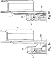
- FIG. 8 is a part of the clutch cover or driving ring 1 of an embodiment of the invention shown, for example, can form a clutch cover of a motor-side single clutch of a double clutch.
- This drive ring (as an example of a "second assembly") is connected via a driver ring 4 with a secondary flange to a DMF (as an example of a "first component") via the one formed in this secondary flange of the ZMS gear - connected for torque transmission of a drive on a gearbox.
- a plurality of circumferentially distributed leaf springs 100 are arranged, wherein a first end of the leaf springs 100 via a first riveting 101 with the driver ring 4 and a (in FIG. 8 not shown in detail) second end of the leaf springs 100 are connected via a second riveting 102 with the driving ring 1.
- the transmission of the torque coming from the drive thus takes place via the secondary flange of the DMF on the driver ring 4 and the driver ring 4 on the leaf springs 100 and of the leaf springs 100 on the driver ring 1. Due to the leaf springs used is the space in the region of the junction between ZMS and double clutch better utilized, since the drive ring is axially movable coupling side attached to the drive ring.
- the leaf springs 100 allow in the axial direction of the clutch considered a soft design and in the circumferential direction a rigid design, so that the torque can be transmitted through the leaf springs and yet the tolerances between ZMS and dual clutch can be compensated.
- the tooth length of the Mit supportivekranzes is so compared to the FIGS. 1 to 7 Removable directly riveted drive ring significantly shortened.
- a collar 4A can be removed at the end of the toothing of the driving ring 4.
- This collar 4A serves as a stop for the ZMS-side toothing in the secondary flange of the ZMS (the present FIG. 8 is not removable). It also serves as a stop for the driving ring on the driving ring.
- FIGS. 9A can be removed, the drive ring according to the axial mobility of the leaf springs 100 maximum in the direction of drive (in Figure 9A "far left”).
- the case achievable maximum distance is in Figure 9A recognizable as a distance between the collar 4A of the driver ring 4 and the motor-side contact surface of the driver ring.
- the Mitauerkranz like FIG. 9B removable "far right” are located. Then all tolerances at the corresponding lower limit and ZMS and double clutch would be pushed together the next. In this position, then the leaf spring is biased the farthest. Between these two positions 9A and 9B, all intermediate positions are conceivable.
- FIGS. 8 and FIGS. 9A and 9B show examples of individual leaf springs. However, this is only to be understood, so that from the teaching of the present invention, individual leaf springs, and leaf spring assemblies, as well as a plurality along the circumference (evenly) distributed leaf springs / leaf spring assemblies are included.
- the type of connection between the leaf springs / leaf spring assemblies and the respective components via riveted joints are alternatively executable differently, for example via screw.
- a maximum distance between the driver ring 4 and the driver ring 1 is further than the theoretical maximum distance between ZMS and double clutch is set, so that in this case a bias in the circumferential direction of the spline due to the axial displacement occurring during assembly and thereby conditional twisting of the driving ring can be adjusted.
- B is the toothing length of the drive ring over the execution of Fig. 1 to 7 significantly shortened.
- a collar At the end of the toothing is a collar. This serves as a stop for the ZMS-side toothing in the flange.
- the connection between the driving ring and driving ring is realized by an axially movable, resilient element, here represented for example by leaf springs which are stiff in the circumferential direction to transmit the torque.
- the drive ring can be leftmost ( Fig. 9A ). This would mean that all tolerances would be at the upper limit and thus ZMS and dual clutch would be furthest apart.
- the drive ring can be located on the far right ( Fig. 9B ). Then all tolerances at the lower limit and ZMS and Doppelkupplung would be pushed together the next. The leaf springs would be the most preloaded. All stepless positions in between are conceivable.
Description
Die Erfindung betrifft eine Drehmomentübertragungsvorrichtung mit einer Steckverbindung zwischen einer ersten Baugruppe und einer zweiten Baugruppe, bzw. zwischen einem Drehschwingungsdämpfer und einer Kupplung, wobei an einer der beiden Baugruppen eine Verzahnung ausgebildet ist und mit einem Zahnkranz. Bevorzugt sind solche Drehmomentübertragungseinrichtungen in Kupplungsaggregaten, wie einer Trockenkupplung, einer Nasskupplung oder einem Drehmomentwandler, und Drehschwingungsdämpfern oder zwischen diesen Elementen zur drehschlüssigen Verbindung einer ersten Baugruppe mit einer zweiten Baugruppe des Kupplungsaggregats bzw. Drehschwingungsdämpfers vorgesehen.The invention relates to a torque transmission device with a plug connection between a first assembly and a second assembly, or between a torsional vibration damper and a coupling, wherein on one of the two components a toothing is formed and with a sprocket. Preferably, such torque transmission devices are provided in clutch units, such as a dry clutch, a wet clutch or a torque converter, and torsional vibration dampers or between these elements for the rotational connection of a first assembly with a second assembly of the clutch assembly or torsional vibration damper.
Gattungsbildende Steckverbindungen werden in Kupplungsaggregaten beispielsweise dann eingesetzt, wenn eine Baugruppe, beispielsweise ein an der Kurbelwelle einer Brennkraftmaschine angebundenes Zweimassenschwungrad und eine andere Baugruppe, beispielsweise eine Doppelkupplung, miteinander zu verbinden sind. Bei der Endmontage von Brennkraftmaschine und Getriebe werden dann die beiden Baugruppen über die Steckverbindung drehfest und zum Ausgleich gegebenenfalls vorhandener Achsversätzen mit geringfügigem Spiel miteinander verbunden.Generic plug-in connections are used in clutch units, for example, when an assembly, for example, a connected to the crankshaft of an internal combustion engine dual-mass flywheel and another assembly, such as a dual clutch to connect to each other. In the final assembly of the internal combustion engine and gearbox then the two modules are rotatably connected via the connector and connected to compensate for any existing axial offsets with slight play together.
Aus der
Aus der
Ein axialer Ausgleich innerhalb eines Antriebstranges eines Fahrzeuges zwischen Antriebsaggregat und Getriebe und hier gerade zwischen Drehschwingungsdämpfer (z.B. Zweimassenschwungrad=ZMS) und Kupplungsaggregat findet üblicherweise an der vorstehend beschriebenen Steckverzahnung statt. So findet beispielsweise auch der Axialausgleich zwischen ZMS und Doppelkupplung üblicherweise über die doppelkupplungsseitige Mitnehmerkranzverzahnung, in welche die Verzahnung des ZMS-Flansches eingreift, statt. Bei der Montage von Motor und Getriebe muss dabei sichergestellt werden, dass die Verzahnungen von ZMS und Doppelkupplung ineinander greifen. Dazu muss die doppelkupplungsseitige Verzahnung am Mitnehmerkranz entsprechend lang ausgeführt sein, damit die Überdeckung beider Teile unter jeder Toleranzlage gewährleistet ist. Dabei ist eine notwendige Länge der Überdeckung auch deshalb so hoch, damit alle Toleranzen von ZMS und Doppelkupplung, aber auch von Motor, Getriebe und Kupplungsglocke an dieser Stelle ausgeglichen werden müssen.An axial compensation within a drive train of a vehicle between drive assembly and transmission and here just between torsional vibration damper (for example, dual mass flywheel = DMF) and clutch unit usually takes place on the above-described spline. Thus, for example, the axial compensation between ZMS and dual clutch usually via the double clutch side Mitnehmerkranzverzahnung, in which engages the toothing of the ZMS flange instead. When installing the engine and gearbox, it must be ensured that the gear teeth of the DMF and the double clutch mesh with each other. For this purpose, the double-clutch side toothing on the carrier ring must be designed to be correspondingly long, so that the overlap of both parts is guaranteed under any tolerance. In this case, a necessary length of the overlap is also so high, so that all tolerances of ZMS and dual clutch, but also of the engine, transmission and clutch bell must be compensated at this point.
Aus der
Aufgabe der Erfindung ist es daher eine Drehmomentübertragungsvorrichtung mit einer Steckverbindung der Eingangs genannten Art derart zu verbessern, dass der axiale Bauraumbedarf der Verbindung zwischen ZMS und Doppelkupplung reduziert wird.The object of the invention is therefore to improve a torque transmission device with a connector of the type mentioned in such a way that the axial space requirement of the connection between ZMS and dual clutch is reduced.
Die Aufgabe wird erfindungsgemäß gelöst durch eine Drehmomentübertragungsvorrichtung mit einer Steckverbindung mit den Merkmalen des Anspruchs 1. Der Axialausgleich wird also z.B. zwischen einem ZMS und einer Doppelkupplung durch einen axial bewegbar federnd angebundenen Zahnkranz realisiert. Die Erfindung ermöglicht es also hier den Bauraum im Bereich der Verbindungsstelle zwischen ZMS und Doppelkupplung besser auszunutzen, indem ein axial bewegliches Element (d.h. der Zahnkranz) kupplungsseitig zwischen Mitnehmerring und Mitnehmerkranz angebracht wird, welches in axialer Richtung weich und in Umfangsrichtung steif ausgeführt ist, damit das Drehmoment übertragen werden kann und trotzdem alle Toleranzen zwischen ZMS und Doppelkupplung ausgeglichen werden können.The object is achieved by a torque transmission device with a connector with the features of
Gemäß der Erfindung ist als axial bewegbare und federnde Verbindung zwischen Zahnkranz und der entsprechend anderen der Baugruppen eine Blattfederverbindung vorgesehen, so dass das Drehmoment von der ersten Baugruppe über die Blattfederverbindung an die zweite Baugruppe übertragen wird. Die Blattfederverbindung kann zumindest eine Blattfeder bzw. ein Blattfederpaket, bevorzugt aber mehrere entlang des Umfangs des Zahnkranzes verteilt angeordnete Blattfedern bzw. Blattfederpakete umfassen.According to the invention, a leaf spring connection is provided as an axially movable and resilient connection between the ring gear and the corresponding other of the assemblies, so that the torque is transmitted from the first assembly via the leaf spring connection to the second assembly. The leaf spring connection may comprise at least one leaf spring or a leaf spring packet, but preferably a plurality of leaf springs or leaf spring packets arranged distributed along the circumference of the toothed ring.
Die Erfindung wird anhand der in den
Figur 1- ein Kupplungsdeckel bzw. Mitnehmerring einer Kupplung als eine Baugruppe einer Steckverbindung in Seitenansicht,
Figur 2- eine Rohform des Zahnkranzes in Draufsicht,
Figur 3- eine geschnittene Teilansicht des Bauteils nach
Figur 1 - Figur 3A
- eine Draufsicht auf die Baueinheit aus dem Bauteil nach
Fig. 1 und einem Zahnkranz, vorliegend verstemmt, Figur 4- eine Detaildarstellung der
Figur 3 Figur 4A- eine Detaildarstellung der
Figur 3A , Figur 5- eine geschnittene Teilansicht eines Bauteils nach
Fig. 1 mit einem mit diesem verbundenen (vorliegend: vernieteten) Zahnkranz, - Figur 5A
- eine Draufsicht auf eine Baueinheit aus dem Bauteil nach
Figur 1entsprechend Figur 5 , Figur 6- eine Detaildarstellung der
Figur 5 - Figur 6A
- eine Detaildarstellung der
Figur 5A , Figur 7- eine Draufsicht auf ein weiteres Ausführungsbeispiel der Baueinheit aus Bauteil des Kupplungsaggregats und Zahnkranz, mit modifiziertem Verbindungsbereich zwischen Bauteil und Zahnkranz,
- FIG. 1
- a clutch cover or driving ring of a coupling as an assembly of a connector in side view,
- FIG. 2
- a raw form of the ring gear in plan view,
- FIG. 3
- a sectional partial view of the component according to
FIG. 1 and a connected thereto (in the following: caulked) sprocket, - FIG. 3A
- a plan view of the assembly from the component to
Fig. 1 and a sprocket, in this case caulked, - FIG. 4
- a detailed view of the
FIG. 3 . - FIG. 4A
- a detailed view of the
FIG. 3A . - FIG. 5
- a sectional partial view of a component according to
Fig. 1 with a connected thereto (riveted in this case) sprocket, - FIG. 5A
- a plan view of a structural unit from the component to
FIG. 1 and a sprocket, riveted accordinglyFIG. 5 . - FIG. 6
- a detailed view of the
FIG. 5 and - FIG. 6A
- a detailed view of the
FIG. 5A . - FIG. 7
- a plan view of another embodiment of the assembly of component of the clutch assembly and ring gear, with modified connection area between the component and sprocket,
Die
In
Die
In
In
Zwischen Mitnehmerring 1 und Mitnehmerkranz 4 sind mehrere entlang des Umfangs verteilte Blattfedern 100 angeordnet, wobei ein erstes Ende der Blattfedern 100 über eine erste Vernietung 101 mit dem Mitnehmerkranz 4 und ein (in
Wie
Wie
In den
Gemäß dem Ausführungsbeispiel der
Es gibt zwei Extrempositionen in der sich der Mitnehmerkranz befinden kann. Zum einen kann der Mitnehmerkranz ganz links stehen (
- 11
- Bauteilcomponent
- 1a1a
- Bauteilcomponent
- 22
- Zahntooth
- 33
- Zahnkranzsprocket
- 3a3a
- Zahnkranzsprocket
- 44
- Zahnprofiltooth profile
- 55
- Außenverzahnungexternal teeth
- 66
- Rohteilblank
- 77
- Lascheflap
- 88th
- Schenkelleg
- 99
- Schenkelleg
- 1010
- Steckverbindungconnector
- 10a10a
- Steckverbindungconnector
- 1111
- Flanschabschnittflange
- 1212
- Öffnungopening
- 1313
- Öffnungopening
- 1414
- EinfädelphaseEinfädelphase
Claims (2)
- Torque transmission apparatus having a plug-in connection (10, 10a) between a first assembly and a second assembly, or between a torsional vibration damper and a clutch, and having a toothed rim, a toothing system being configured on one of the two assemblies, and the toothed rim (3, 3a) which engages into the toothing system being attached in a sprung and axially movable manner to the corresponding other one of the two assemblies, a leaf spring connection being provided as an axially movable and sprung connection between the toothed rim (3, 3a) and the corresponding other one of the assemblies, with the result that the torque is transmitted from the first assembly via the leaf spring connection to the second assembly, characterized in that the first assembly is a secondary-side flange of a dual-mass flywheel and the second assembly is a flanged sleeve (1), the toothed rim is configured as a driver rim (4), and the driver rim (4) is connected to the flanged sleeve (1) via leaf springs (100), with the result that the driver rim (4) is attached to the flanged sleeve (1) on the clutch side in an axially movable manner.
- Torque transmission apparatus (10) according to either of Claims 1 and 2, the leaf spring connection comprising at least one leaf spring or one leaf spring assembly, but preferably a plurality of leaf springs or leaf spring assemblies which are arranged distributed along the circumference of the toothed rim.
Applications Claiming Priority (2)
| Application Number | Priority Date | Filing Date | Title |
|---|---|---|---|
| DE102011105682 | 2011-06-22 | ||
| PCT/DE2012/000585 WO2012175065A1 (en) | 2011-06-22 | 2012-06-04 | Torque transmission device |
Publications (2)
| Publication Number | Publication Date |
|---|---|
| EP2724041A1 EP2724041A1 (en) | 2014-04-30 |
| EP2724041B1 true EP2724041B1 (en) | 2018-08-08 |
Family
ID=46507825
Family Applications (1)
| Application Number | Title | Priority Date | Filing Date |
|---|---|---|---|
| EP12734784.7A Not-in-force EP2724041B1 (en) | 2011-06-22 | 2012-06-04 | Torque transmission device |
Country Status (4)
| Country | Link |
|---|---|
| EP (1) | EP2724041B1 (en) |
| CN (1) | CN103547824A (en) |
| DE (1) | DE102012209344A1 (en) |
| WO (1) | WO2012175065A1 (en) |
Families Citing this family (4)
| Publication number | Priority date | Publication date | Assignee | Title |
|---|---|---|---|---|
| US9382968B2 (en) * | 2014-01-14 | 2016-07-05 | Electro-Motive Diesel, Inc. | Engine system having torsional coupling with thin web flywheel |
| US9291210B2 (en) * | 2014-08-11 | 2016-03-22 | GM Global Technology Operations LLC | Flywheel and dual clutch module assembly |
| DE102015203943A1 (en) * | 2015-03-05 | 2016-09-08 | Schaeffler Technologies AG & Co. KG | Tilger for reducing rotational nonuniformity |
| CN111609048B (en) * | 2020-06-02 | 2021-11-16 | 浙江华信汽车零部件有限公司 | Adjustable clutch cover assembly |
Citations (2)
| Publication number | Priority date | Publication date | Assignee | Title |
|---|---|---|---|---|
| EP1617096A2 (en) * | 2004-07-16 | 2006-01-18 | Zf Friedrichshafen Ag | Torque transmission assembly between units of a motor vehicle drive train |
| DE102006019977A1 (en) * | 2005-05-19 | 2006-11-23 | Luk Lamellen Und Kupplungsbau Beteiligungs Kg | Torque transmitting arrangement for drive train of vehicle, comprises adjusting device for central displacement |
Family Cites Families (8)
| Publication number | Priority date | Publication date | Assignee | Title |
|---|---|---|---|---|
| DE102005037514B4 (en) | 2004-09-03 | 2021-09-30 | Schaeffler Technologies AG & Co. KG | Torque transmission device |
| EP1850025B1 (en) * | 2004-09-03 | 2012-10-10 | Schaeffler Technologies AG & Co. KG | Torque transmission device |
| EP1731786A3 (en) * | 2005-06-09 | 2007-05-02 | LuK Lamellen und Kupplungsbau Beteiligungs KG | Clutch disc |
| DE102005045158A1 (en) * | 2005-09-21 | 2007-03-22 | Zf Friedrichshafen Ag | Dual clutch unit, comprises axial positioned support unit also assisting during assembly |
| DE102007004203A1 (en) * | 2007-01-27 | 2008-07-31 | Zf Friedrichshafen Ag | Drive system for a vehicle |
| DE102008027443A1 (en) | 2007-07-02 | 2009-01-08 | Luk Lamellen Und Kupplungsbau Beteiligungs Kg | A clutch unit |
| DE102008032273B4 (en) * | 2008-02-18 | 2021-12-23 | Borgwarner Inc. | Coupling device with a flex plate |
| EP2643609B1 (en) * | 2010-11-24 | 2015-01-14 | Schaeffler Technologies GmbH & Co. KG | Prestressing device of a shaft-hub connection |
-
2012
- 2012-06-04 WO PCT/DE2012/000585 patent/WO2012175065A1/en active Application Filing
- 2012-06-04 DE DE102012209344A patent/DE102012209344A1/en not_active Withdrawn
- 2012-06-04 CN CN201280024968.7A patent/CN103547824A/en active Pending
- 2012-06-04 EP EP12734784.7A patent/EP2724041B1/en not_active Not-in-force
Patent Citations (2)
| Publication number | Priority date | Publication date | Assignee | Title |
|---|---|---|---|---|
| EP1617096A2 (en) * | 2004-07-16 | 2006-01-18 | Zf Friedrichshafen Ag | Torque transmission assembly between units of a motor vehicle drive train |
| DE102006019977A1 (en) * | 2005-05-19 | 2006-11-23 | Luk Lamellen Und Kupplungsbau Beteiligungs Kg | Torque transmitting arrangement for drive train of vehicle, comprises adjusting device for central displacement |
Also Published As
| Publication number | Publication date |
|---|---|
| EP2724041A1 (en) | 2014-04-30 |
| CN103547824A (en) | 2014-01-29 |
| DE102012209344A1 (en) | 2012-12-27 |
| WO2012175065A1 (en) | 2012-12-27 |
Similar Documents
| Publication | Publication Date | Title |
|---|---|---|
| EP3093516B1 (en) | Bracing assembly for a drive train of a motor vehicle | |
| WO2007000151A2 (en) | Clutch unit | |
| WO2008046379A1 (en) | Clutch unit | |
| WO2007000131A2 (en) | Coupling system | |
| DE102011102117A1 (en) | Clamping device for a shaft-hub connection | |
| DE102012221653A1 (en) | Wet clutch for vehicle, has input plate carrier which is connected to drive and/or output plate carrier connected to transmission input shaft, and clutch cover and drive cup are removably connected in torque flow by standing under bias | |
| WO2021043364A1 (en) | Drive unit for a hybrid drive train | |
| EP2724041B1 (en) | Torque transmission device | |
| DE102021104113A1 (en) | Torque transmission device, in particular for a drive train of a motor vehicle | |
| DE102010022916A1 (en) | Torque transfer device | |
| DE102013215582A1 (en) | Torque transmission device and plug connection for this | |
| DE102005049433A1 (en) | Axial plug-in connection, has profile unit and counter profile unit profiled in such a manner that relative movement is provided by directly profiling profile unit and counter unit for raising torque during axially assembling | |
| DE102010050462A1 (en) | Connection assembly for use in clutch assembly for rotationally locked connection of two components, comprises component section, where gear ring is joined to component section | |
| DE102013206675A1 (en) | Powertrain construction kit for motor vehicles | |
| EP1979648A1 (en) | Torque transmitting device | |
| DE19810297A1 (en) | Automotive transmission linkage between torque converter | |
| DE102010032658A1 (en) | Torque transmission device i.e. clutch assembly, has clamping element carried by component and including even individual profiling, which intervenes in teeth profile of component, and support plate embracing component | |
| EP1657472B1 (en) | Axial plug-in connection | |
| DE102017114444A1 (en) | Tilgereinrichtung | |
| DE102010006472A1 (en) | Torque transmission device for use in vehicle drive train between crankshaft of internal combustion engine and drive input shaft of drive, has clutch assembly with friction clutch and serially arranged torsional vibration damper | |
| EP2516872B1 (en) | Device having a plug-in connection | |
| DE102015212896A1 (en) | Hub part for a spline | |
| WO2018177468A1 (en) | Shaft-hub connection comprising clamping element for splines and drive train | |
| DE102019130273A1 (en) | Torque transmission device | |
| DE102016207250A1 (en) | Torsion damper assembly and drivetrain |
Legal Events
| Date | Code | Title | Description |
|---|---|---|---|
| PUAI | Public reference made under article 153(3) epc to a published international application that has entered the european phase |
Free format text: ORIGINAL CODE: 0009012 |
|
| 17P | Request for examination filed |
Effective date: 20140122 |
|
| AK | Designated contracting states |
Kind code of ref document: A1 Designated state(s): AL AT BE BG CH CY CZ DE DK EE ES FI FR GB GR HR HU IE IS IT LI LT LU LV MC MK MT NL NO PL PT RO RS SE SI SK SM TR |
|
| DAX | Request for extension of the european patent (deleted) | ||
| RAP1 | Party data changed (applicant data changed or rights of an application transferred) |
Owner name: SCHAEFFLER TECHNOLOGIES AG & CO. KG |
|
| STAA | Information on the status of an ep patent application or granted ep patent |
Free format text: STATUS: EXAMINATION IS IN PROGRESS |
|
| 17Q | First examination report despatched |
Effective date: 20161123 |
|
| GRAP | Despatch of communication of intention to grant a patent |
Free format text: ORIGINAL CODE: EPIDOSNIGR1 |
|
| STAA | Information on the status of an ep patent application or granted ep patent |
Free format text: STATUS: GRANT OF PATENT IS INTENDED |
|
| INTG | Intention to grant announced |
Effective date: 20180117 |
|
| GRAS | Grant fee paid |
Free format text: ORIGINAL CODE: EPIDOSNIGR3 |
|
| GRAA | (expected) grant |
Free format text: ORIGINAL CODE: 0009210 |
|
| STAA | Information on the status of an ep patent application or granted ep patent |
Free format text: STATUS: THE PATENT HAS BEEN GRANTED |
|
| AK | Designated contracting states |
Kind code of ref document: B1 Designated state(s): AL AT BE BG CH CY CZ DE DK EE ES FI FR GB GR HR HU IE IS IT LI LT LU LV MC MK MT NL NO PL PT RO RS SE SI SK SM TR |
|
| REG | Reference to a national code |
Ref country code: GB Ref legal event code: FG4D Free format text: NOT ENGLISH |
|
| REG | Reference to a national code |
Ref country code: CH Ref legal event code: EP Ref country code: AT Ref legal event code: REF Ref document number: 1027360 Country of ref document: AT Kind code of ref document: T Effective date: 20180815 |
|
| REG | Reference to a national code |
Ref country code: IE Ref legal event code: FG4D Free format text: LANGUAGE OF EP DOCUMENT: GERMAN |
|
| REG | Reference to a national code |
Ref country code: DE Ref legal event code: R096 Ref document number: 502012013213 Country of ref document: DE |
|
| REG | Reference to a national code |
Ref country code: NL Ref legal event code: MP Effective date: 20180808 |
|
| REG | Reference to a national code |
Ref country code: LT Ref legal event code: MG4D |
|
| PG25 | Lapsed in a contracting state [announced via postgrant information from national office to epo] |
Ref country code: NO Free format text: LAPSE BECAUSE OF FAILURE TO SUBMIT A TRANSLATION OF THE DESCRIPTION OR TO PAY THE FEE WITHIN THE PRESCRIBED TIME-LIMIT Effective date: 20181108 Ref country code: SE Free format text: LAPSE BECAUSE OF FAILURE TO SUBMIT A TRANSLATION OF THE DESCRIPTION OR TO PAY THE FEE WITHIN THE PRESCRIBED TIME-LIMIT Effective date: 20180808 Ref country code: GR Free format text: LAPSE BECAUSE OF FAILURE TO SUBMIT A TRANSLATION OF THE DESCRIPTION OR TO PAY THE FEE WITHIN THE PRESCRIBED TIME-LIMIT Effective date: 20181109 Ref country code: FI Free format text: LAPSE BECAUSE OF FAILURE TO SUBMIT A TRANSLATION OF THE DESCRIPTION OR TO PAY THE FEE WITHIN THE PRESCRIBED TIME-LIMIT Effective date: 20180808 Ref country code: LT Free format text: LAPSE BECAUSE OF FAILURE TO SUBMIT A TRANSLATION OF THE DESCRIPTION OR TO PAY THE FEE WITHIN THE PRESCRIBED TIME-LIMIT Effective date: 20180808 Ref country code: RS Free format text: LAPSE BECAUSE OF FAILURE TO SUBMIT A TRANSLATION OF THE DESCRIPTION OR TO PAY THE FEE WITHIN THE PRESCRIBED TIME-LIMIT Effective date: 20180808 Ref country code: PL Free format text: LAPSE BECAUSE OF FAILURE TO SUBMIT A TRANSLATION OF THE DESCRIPTION OR TO PAY THE FEE WITHIN THE PRESCRIBED TIME-LIMIT Effective date: 20180808 Ref country code: IS Free format text: LAPSE BECAUSE OF FAILURE TO SUBMIT A TRANSLATION OF THE DESCRIPTION OR TO PAY THE FEE WITHIN THE PRESCRIBED TIME-LIMIT Effective date: 20181208 Ref country code: BG Free format text: LAPSE BECAUSE OF FAILURE TO SUBMIT A TRANSLATION OF THE DESCRIPTION OR TO PAY THE FEE WITHIN THE PRESCRIBED TIME-LIMIT Effective date: 20181108 Ref country code: NL Free format text: LAPSE BECAUSE OF FAILURE TO SUBMIT A TRANSLATION OF THE DESCRIPTION OR TO PAY THE FEE WITHIN THE PRESCRIBED TIME-LIMIT Effective date: 20180808 |
|
| PG25 | Lapsed in a contracting state [announced via postgrant information from national office to epo] |
Ref country code: AL Free format text: LAPSE BECAUSE OF FAILURE TO SUBMIT A TRANSLATION OF THE DESCRIPTION OR TO PAY THE FEE WITHIN THE PRESCRIBED TIME-LIMIT Effective date: 20180808 Ref country code: LV Free format text: LAPSE BECAUSE OF FAILURE TO SUBMIT A TRANSLATION OF THE DESCRIPTION OR TO PAY THE FEE WITHIN THE PRESCRIBED TIME-LIMIT Effective date: 20180808 Ref country code: HR Free format text: LAPSE BECAUSE OF FAILURE TO SUBMIT A TRANSLATION OF THE DESCRIPTION OR TO PAY THE FEE WITHIN THE PRESCRIBED TIME-LIMIT Effective date: 20180808 |
|
| PG25 | Lapsed in a contracting state [announced via postgrant information from national office to epo] |
Ref country code: EE Free format text: LAPSE BECAUSE OF FAILURE TO SUBMIT A TRANSLATION OF THE DESCRIPTION OR TO PAY THE FEE WITHIN THE PRESCRIBED TIME-LIMIT Effective date: 20180808 Ref country code: ES Free format text: LAPSE BECAUSE OF FAILURE TO SUBMIT A TRANSLATION OF THE DESCRIPTION OR TO PAY THE FEE WITHIN THE PRESCRIBED TIME-LIMIT Effective date: 20180808 Ref country code: CZ Free format text: LAPSE BECAUSE OF FAILURE TO SUBMIT A TRANSLATION OF THE DESCRIPTION OR TO PAY THE FEE WITHIN THE PRESCRIBED TIME-LIMIT Effective date: 20180808 Ref country code: IT Free format text: LAPSE BECAUSE OF FAILURE TO SUBMIT A TRANSLATION OF THE DESCRIPTION OR TO PAY THE FEE WITHIN THE PRESCRIBED TIME-LIMIT Effective date: 20180808 Ref country code: RO Free format text: LAPSE BECAUSE OF FAILURE TO SUBMIT A TRANSLATION OF THE DESCRIPTION OR TO PAY THE FEE WITHIN THE PRESCRIBED TIME-LIMIT Effective date: 20180808 |
|
| REG | Reference to a national code |
Ref country code: DE Ref legal event code: R097 Ref document number: 502012013213 Country of ref document: DE |
|
| PG25 | Lapsed in a contracting state [announced via postgrant information from national office to epo] |
Ref country code: SM Free format text: LAPSE BECAUSE OF FAILURE TO SUBMIT A TRANSLATION OF THE DESCRIPTION OR TO PAY THE FEE WITHIN THE PRESCRIBED TIME-LIMIT Effective date: 20180808 Ref country code: DK Free format text: LAPSE BECAUSE OF FAILURE TO SUBMIT A TRANSLATION OF THE DESCRIPTION OR TO PAY THE FEE WITHIN THE PRESCRIBED TIME-LIMIT Effective date: 20180808 Ref country code: SK Free format text: LAPSE BECAUSE OF FAILURE TO SUBMIT A TRANSLATION OF THE DESCRIPTION OR TO PAY THE FEE WITHIN THE PRESCRIBED TIME-LIMIT Effective date: 20180808 |
|
| PLBE | No opposition filed within time limit |
Free format text: ORIGINAL CODE: 0009261 |
|
| STAA | Information on the status of an ep patent application or granted ep patent |
Free format text: STATUS: NO OPPOSITION FILED WITHIN TIME LIMIT |
|
| 26N | No opposition filed |
Effective date: 20190509 |
|
| PG25 | Lapsed in a contracting state [announced via postgrant information from national office to epo] |
Ref country code: SI Free format text: LAPSE BECAUSE OF FAILURE TO SUBMIT A TRANSLATION OF THE DESCRIPTION OR TO PAY THE FEE WITHIN THE PRESCRIBED TIME-LIMIT Effective date: 20180808 |
|
| PG25 | Lapsed in a contracting state [announced via postgrant information from national office to epo] |
Ref country code: MC Free format text: LAPSE BECAUSE OF FAILURE TO SUBMIT A TRANSLATION OF THE DESCRIPTION OR TO PAY THE FEE WITHIN THE PRESCRIBED TIME-LIMIT Effective date: 20180808 |
|
| REG | Reference to a national code |
Ref country code: CH Ref legal event code: PL |
|
| GBPC | Gb: european patent ceased through non-payment of renewal fee |
Effective date: 20190604 |
|
| REG | Reference to a national code |
Ref country code: BE Ref legal event code: MM Effective date: 20190630 |
|
| PG25 | Lapsed in a contracting state [announced via postgrant information from national office to epo] |
Ref country code: TR Free format text: LAPSE BECAUSE OF FAILURE TO SUBMIT A TRANSLATION OF THE DESCRIPTION OR TO PAY THE FEE WITHIN THE PRESCRIBED TIME-LIMIT Effective date: 20180808 |
|
| PG25 | Lapsed in a contracting state [announced via postgrant information from national office to epo] |
Ref country code: IE Free format text: LAPSE BECAUSE OF NON-PAYMENT OF DUE FEES Effective date: 20190604 Ref country code: GB Free format text: LAPSE BECAUSE OF NON-PAYMENT OF DUE FEES Effective date: 20190604 |
|
| PG25 | Lapsed in a contracting state [announced via postgrant information from national office to epo] |
Ref country code: LI Free format text: LAPSE BECAUSE OF NON-PAYMENT OF DUE FEES Effective date: 20190630 Ref country code: BE Free format text: LAPSE BECAUSE OF NON-PAYMENT OF DUE FEES Effective date: 20190630 Ref country code: LU Free format text: LAPSE BECAUSE OF NON-PAYMENT OF DUE FEES Effective date: 20190604 Ref country code: CH Free format text: LAPSE BECAUSE OF NON-PAYMENT OF DUE FEES Effective date: 20190630 |
|
| PG25 | Lapsed in a contracting state [announced via postgrant information from national office to epo] |
Ref country code: PT Free format text: LAPSE BECAUSE OF FAILURE TO SUBMIT A TRANSLATION OF THE DESCRIPTION OR TO PAY THE FEE WITHIN THE PRESCRIBED TIME-LIMIT Effective date: 20181208 |
|
| REG | Reference to a national code |
Ref country code: AT Ref legal event code: MM01 Ref document number: 1027360 Country of ref document: AT Kind code of ref document: T Effective date: 20190604 |
|
| PG25 | Lapsed in a contracting state [announced via postgrant information from national office to epo] |
Ref country code: AT Free format text: LAPSE BECAUSE OF NON-PAYMENT OF DUE FEES Effective date: 20190604 |
|
| PG25 | Lapsed in a contracting state [announced via postgrant information from national office to epo] |
Ref country code: CY Free format text: LAPSE BECAUSE OF FAILURE TO SUBMIT A TRANSLATION OF THE DESCRIPTION OR TO PAY THE FEE WITHIN THE PRESCRIBED TIME-LIMIT Effective date: 20180808 |
|
| PG25 | Lapsed in a contracting state [announced via postgrant information from national office to epo] |
Ref country code: MT Free format text: LAPSE BECAUSE OF FAILURE TO SUBMIT A TRANSLATION OF THE DESCRIPTION OR TO PAY THE FEE WITHIN THE PRESCRIBED TIME-LIMIT Effective date: 20180808 Ref country code: HU Free format text: LAPSE BECAUSE OF FAILURE TO SUBMIT A TRANSLATION OF THE DESCRIPTION OR TO PAY THE FEE WITHIN THE PRESCRIBED TIME-LIMIT; INVALID AB INITIO Effective date: 20120604 |
|
| PGFP | Annual fee paid to national office [announced via postgrant information from national office to epo] |
Ref country code: FR Payment date: 20210622 Year of fee payment: 10 |
|
| PGFP | Annual fee paid to national office [announced via postgrant information from national office to epo] |
Ref country code: DE Payment date: 20210819 Year of fee payment: 10 |
|
| PG25 | Lapsed in a contracting state [announced via postgrant information from national office to epo] |
Ref country code: MK Free format text: LAPSE BECAUSE OF FAILURE TO SUBMIT A TRANSLATION OF THE DESCRIPTION OR TO PAY THE FEE WITHIN THE PRESCRIBED TIME-LIMIT Effective date: 20180808 |
|
| REG | Reference to a national code |
Ref country code: DE Ref legal event code: R119 Ref document number: 502012013213 Country of ref document: DE |
|
| PG25 | Lapsed in a contracting state [announced via postgrant information from national office to epo] |
Ref country code: FR Free format text: LAPSE BECAUSE OF NON-PAYMENT OF DUE FEES Effective date: 20220630 |
|
| PG25 | Lapsed in a contracting state [announced via postgrant information from national office to epo] |
Ref country code: DE Free format text: LAPSE BECAUSE OF NON-PAYMENT OF DUE FEES Effective date: 20230103 |
|
| P01 | Opt-out of the competence of the unified patent court (upc) registered |
Effective date: 20230522 |