EP2724036B1 - Bauteil zur aufnahme und/oder übertragung von mechanischen kräften und/oder momenten, ein verfahren zu dessen herstellung und dessen verwendung - Google Patents
Bauteil zur aufnahme und/oder übertragung von mechanischen kräften und/oder momenten, ein verfahren zu dessen herstellung und dessen verwendung Download PDFInfo
- Publication number
- EP2724036B1 EP2724036B1 EP12745411.4A EP12745411A EP2724036B1 EP 2724036 B1 EP2724036 B1 EP 2724036B1 EP 12745411 A EP12745411 A EP 12745411A EP 2724036 B1 EP2724036 B1 EP 2724036B1
- Authority
- EP
- European Patent Office
- Prior art keywords
- hollow
- component element
- profiled
- dimensionally stable
- component
- Prior art date
- Legal status (The legal status is an assumption and is not a legal conclusion. Google has not performed a legal analysis and makes no representation as to the accuracy of the status listed.)
- Active
Links
Images


Classifications
-
- F—MECHANICAL ENGINEERING; LIGHTING; HEATING; WEAPONS; BLASTING
- F16—ENGINEERING ELEMENTS AND UNITS; GENERAL MEASURES FOR PRODUCING AND MAINTAINING EFFECTIVE FUNCTIONING OF MACHINES OR INSTALLATIONS; THERMAL INSULATION IN GENERAL
- F16C—SHAFTS; FLEXIBLE SHAFTS; ELEMENTS OR CRANKSHAFT MECHANISMS; ROTARY BODIES OTHER THAN GEARING ELEMENTS; BEARINGS
- F16C7/00—Connecting-rods or like links pivoted at both ends; Construction of connecting-rod heads
- F16C7/02—Constructions of connecting-rods with constant length
- F16C7/026—Constructions of connecting-rods with constant length made of fibre reinforced resin
-
- F—MECHANICAL ENGINEERING; LIGHTING; HEATING; WEAPONS; BLASTING
- F16—ENGINEERING ELEMENTS AND UNITS; GENERAL MEASURES FOR PRODUCING AND MAINTAINING EFFECTIVE FUNCTIONING OF MACHINES OR INSTALLATIONS; THERMAL INSULATION IN GENERAL
- F16C—SHAFTS; FLEXIBLE SHAFTS; ELEMENTS OR CRANKSHAFT MECHANISMS; ROTARY BODIES OTHER THAN GEARING ELEMENTS; BEARINGS
- F16C3/00—Shafts; Axles; Cranks; Eccentrics
- F16C3/02—Shafts; Axles
- F16C3/026—Shafts made of fibre reinforced resin
-
- Y—GENERAL TAGGING OF NEW TECHNOLOGICAL DEVELOPMENTS; GENERAL TAGGING OF CROSS-SECTIONAL TECHNOLOGIES SPANNING OVER SEVERAL SECTIONS OF THE IPC; TECHNICAL SUBJECTS COVERED BY FORMER USPC CROSS-REFERENCE ART COLLECTIONS [XRACs] AND DIGESTS
- Y10—TECHNICAL SUBJECTS COVERED BY FORMER USPC
- Y10T—TECHNICAL SUBJECTS COVERED BY FORMER US CLASSIFICATION
- Y10T29/00—Metal working
- Y10T29/49—Method of mechanical manufacture
- Y10T29/49826—Assembling or joining
- Y10T29/49945—Assembling or joining by driven force fit
-
- Y—GENERAL TAGGING OF NEW TECHNOLOGICAL DEVELOPMENTS; GENERAL TAGGING OF CROSS-SECTIONAL TECHNOLOGIES SPANNING OVER SEVERAL SECTIONS OF THE IPC; TECHNICAL SUBJECTS COVERED BY FORMER USPC CROSS-REFERENCE ART COLLECTIONS [XRACs] AND DIGESTS
- Y10—TECHNICAL SUBJECTS COVERED BY FORMER USPC
- Y10T—TECHNICAL SUBJECTS COVERED BY FORMER US CLASSIFICATION
- Y10T74/00—Machine element or mechanism
- Y10T74/21—Elements
- Y10T74/2142—Pitmans and connecting rods
Definitions
- the present invention relates to a component for receiving and / or transmitting mechanical forces and / or moments, a method for its production and its use.
- Such components are well known. Only exemplary is the DE 10 2006 058 377 B4 referred to, which is directed to a rod for structural reinforcement of a fuselage structure of an aircraft, which is formed from two end-mounted, dimensionally stable component elements and a hollow-profiled component element made of fiber-reinforced plastic, which is bordered by the two dimensionally stable component elements.
- such components have all proved to be consistently disadvantageous, since their design is often complex, not sufficiently dimensionally stable and relatively high weight, at the same time can not absorb and transmit high forces and / or moments, with concomitant no satisfactory strength and Have stiffness values. In addition, their life is usually not very high and their production are very costly.
- the document DE 20 2005 010 293 V1 discloses a force introduction element on struts made of fiber composite material.
- the present invention is therefore based on the object to provide a component for receiving and / or transmission of mechanical forces and / or moments available, with which can be prevented the above disadvantages, which therefore structurally particularly simple, at the same time compact and dimensionally stable and very is light-weight construction, allows transmission of high forces and moments, concomitantly has a very high strength and rigidity, and has a long life and is extremely inexpensive to manufacture, and to provide a method for its production and use thereof.
- the component according to the invention for receiving and / or transmitting mechanical forces and / or moments comprising at least one dimensionally stable component element with at least one hollow profiled section and at least one hollow profiled component element made of fiber-reinforced plastic, which can be partially absorbed by the hollow profiled portion of the dimensionally stable component element and in The hollow profiled portion of the dimensionally stable component element via radially inwardly extending projections and / or radially outwardly extending recesses, recesses or openings is positively arranged, wherein the inner circumference of the hollow profiled portion of the dimensionally stable component element and the outer periphery of the hollow-profiled component element of fiber-reinforced plastic match each other or - as a result of never completely exclude tolerance deviations in the production - at least substantially coincide timmen, a particularly simple, also compact and dimensionally stable construction of the component of relatively low weight is achieved.
- the component according to the invention has a very high strength and rigidity. Due to the fact that the inner circumference of the hollow profiled section of the dimensionally stable component element and the outer circumference of the hollow profiled component element made of fiber-reinforced plastic coincide with each other or at least substantially coincide, a direction-oriented deformation of the fibers of the hollow profiled component element made of fiber-reinforced plastic is ensured.
- the molding or applying takes place without any wrinkling, since the inner circumference of the hollow profiled portion of the dimensionally stable component element and the outer circumference of the hollow profiled component element the same, at least substantially, ie largely or largely the same is.
- the fibers of the hollow-profiled component element made of fiber-reinforced plastic are thus not kinked, compressed, warped or otherwise subjected to constant loading.
- a positive connection between the at least one dimensionally stable component element and the at least one hollow-profiled component element made of fiber-reinforced plastic is obtained as a result of the construction of the component according to the invention.
- the production of the component according to the invention is extremely simple and less labor-intensive and is therefore extremely inexpensive.
- the projections, which extend radially inwardly, and / or the recesses, recesses or openings, which extend radially outwardly, advantageously arranged uniformly spaced from one another over the inner circumference of the hollow profiled portion of the dimensionally stable component element ,
- the radially inwardly extending elevations and / or the radially outwardly extending recesses, recesses or openings according to claim 3 are elongate, elongated, bead-like, finger-shaped, meandering, wedge-shaped, angled, circular, elliptical, elliptical, oval , triangular, quadrangular, square or rectangular, polygonal, trapezoidal, parallelogram or polygonal and / or formed as a combination thereof, whereby tensile, compressive and torsional forces absorb, initiate and transfer equally.
- the radially inwardly extending projections and / or radially outwardly extending recesses, recesses or openings are arranged axially and / or at an angle to the longitudinal axis of the dimensionally stable component element and the hollow-profiled component element. In this way, tensile, compressive and also torsional forces can be transmitted by the component according to the invention.
- the elevations and / or depressions, recesses or openings are preferably equipped with continuous transitions to / into the adjacent area (s).
- the bumps and / or depressions, recesses or breakthroughs are continuous, i. "soft” or "supple", in the / the adjacent or adjacent thereto area / e over or run out so far. Edged, angular or sharp transitions, which can quickly lead to damage of the fiber-reinforced plastic and thus to a failure of the entire component element, are avoided.
- the dimensionally stable component element at least partially, in particular in a region of the hollow-profiled section, and the hollow-profiled component element according to claim 8, an outer periphery of the same shape and dimension.
- the dimensionally stable component element and / or the hollow-profiled component element according to claim 9 formed lightweight construction and / or corrosion resistant / are.
- the dimensionally stable component element according to claim 10 made of metal, in particular steel, stainless steel, aluminum, titanium, an alloy thereof and / or plastic, in particular polyimide (PI), polyoxymethylene (POM) or polytetrafluoroethylene (PTFE), with or without Alumina, aluminum nitride, aramid, basalt, boron nitride, glass, graphite, carbon, nylon, polyethylene, polyester, silicon carbide, silicon nitride and / or ceramic fiber reinforcement, and / or a combination thereof ,
- PI polyimide
- POM polyoxymethylene
- PTFE polytetrafluoroethylene
- the dimensionally stable component element by milling, turning, grinding or the like surface treatment, casting or investment casting, pulling or deep drawing and / or, in particular subsequent, welding and / or a combination thereof can be produced.
- the invention provides that the dimensionally stable component element according to claim 12 as a connection or connecting element, fitting, flange, Einsteckkupplung for the connection of at least one hollow-profiled component element made of fiber-reinforced plastic, node element for a Truss or a truss structure or the like connecting body, in particular with a joint eye, condyle or the like force and / or Momentenein suddenlys- or -übertragungselement is formed.
- the hollow-profile fiber-reinforced plastic structural member of claim 13 is comprised of alumina, aluminum nitride, aramid, basalt, boron nitride, glass, graphite, carbon, nylon, polyethylene, polyester, silicon carbide, silicon nitride and / or ceramic fibers and / or a combination thereof reinforced and / or formed from fiber composite material.
- hollow-profiled fiber-reinforced plastic component element according to claim 14 by a prepreg process, wet impregnation process or Resin Transfer Molding (RTM) method and / or a combination thereof or the like process for the production of fiber composites can be produced.
- RTM Resin Transfer Molding
- the hollow-profiled component element made of fiber-reinforced plastic in cross-section is preferably round, elliptical, elliptical, oval, triangular, quadrangular, square or rectangular, polygonal, trapezoidal, parallelogram or polygonal and / or formed as a combination thereof.
- the dimensionally stable component element and / or the hollow-profiled component element of fiber-reinforced plastic in particular completely or partially, oblong, elongated, curved, meander-shaped, wavy, serpentine, angled, (semi-) circular, (semi-circular) elliptical, curved, curved and / or shaped as a combination thereof.
- the dimensionally stable component element and / or the hollow-profiled component element can extend over its entire length or over part of it substantially axially or axially parallel and / or in any other deviating manner as desired have other spatial forms.
- the invention provides that the dimensionally stable component element and / or the hollow-profiled component element made of fiber-reinforced plastic according to claim 17, in particular completely or partially, is arranged in at least one spatial plane / are.
- the dimensionally stable component element and / or the hollow-profiled component element can extend completely or partially in a single spatial plane or in a plurality, in particular in two or three, spatial planes.
- the method according to the invention for producing a component for receiving and / or transmitting mechanical forces and / or moments comprising at least one dimensionally stable component element with a hollow profiled section and at least one hollow profiled component element made of fiber-reinforced plastic, wherein the at least one hollow-profiled component element made of fiber-reinforced plastic partially pushed into one end in the hollow profiled portion of the dimensionally stable component element and is received by the hollow profiled portion of the dimensionally stable component element and then by an inserted into the hollow profiled component element made of fiber reinforced plastic inflatable element with its outer circumference form-fit to the inner periphery of the dimensionally stable component element in the region of hollow-shaped portion (on) is pressed by the inflatable element after introduction into the hollow profiled Baut
- the method according to the invention is extremely simple, less labor-intensive and, above all, cost-effective Handling overall proved to be particularly
- the hollow profiled component element is radially deformed before the partial insertion of the end in the hollow profiled portion of the dimensionally stable component element, such that the outer periphery of the hollow profiled component element is smaller than the inner circumference, in particular arranged on the inner circumference, itself radially inwardly extending elevations, the dimensionally stable component element in the region of the hollow-shaped portion is.
- the hollow-profiled component element according to claim 20 with its outer circumference form fit to the inner circumference and on the inner circumference, radially inwardly extending elevations and / or radially outwardly extending recesses, recesses or openings of the dimensionally stable component element in the area from the hollow-shaped portion (an-) pressed, wherein the inner circumference of the hollow-profiled portion of the dimensionally stable component element and the outer circumference of the hollow-profiled component element coincide with each other or at least substantially coincide.
- the hollow profiled component element is pressurized by the inflatable element until its complete curing.
- the hollow profiled component element according to claim 22 of the inflatable element is preferably at a pressure of about 2 to about 10 bar, in particular of about 4 to about 8 bar, preferably from about 6 bar, applied.
- the component according to the invention in a very advantageous manner in vehicles, especially in aircraft or aircraft of aerospace, preferably in aircraft and spacecraft, especially in watercraft, preferably in a submarine or hovercraft (hovercraft), or in particular Land vehicles, preferably in a passenger car, passenger car, such as a bus or minibus, truck or RV, use.
- vehicles especially in aircraft or aircraft of aerospace, preferably in aircraft and spacecraft, especially in watercraft, preferably in a submarine or hovercraft (hovercraft), or in particular Land vehicles, preferably in a passenger car, passenger car, such as a bus or minibus, truck or RV, use.
- the component according to the invention is particularly suitable for receiving and / or transmitting mechanical forces and / or moments and in particular struts transmitting mechanical and compressive forces and / or torsional forces and / or tubular or rod-shaped connecting elements and / or trusses or Truss structures and / or drive shafts, preferably with at least one or more terminally arranged connection elements, joint eyes, condyle or the like Krafteintechnischs- or - appreciatedtragungsettin, in vehicles, most preferably in aircraft and spacecraft as support or stabilization struts for structural reinforcement of a fuselage structure and in land vehicles as support or stabilizing struts for the structural reinforcement of a body structure.
- the component 10 according to the invention is in vehicles, in particular in aircraft or aeronautical aircraft, preferably in aircraft and spacecraft, in particular in watercraft, preferably in a submarine or hovercraft, or in particular in land vehicles, preferably in a passenger car, passenger car, such as a bus or minibus, truck or RV provided.
- the component 10 according to the invention is particularly suitable for receiving and / or transmitting mechanical forces and / or moments and in particular as mechanical tensile and compressive forces and / or torsional forces transmitted struts and / or tubular or rod-shaped connecting elements and / or trusses or truss structures and / or drive shafts, preferably with at least one or more terminally arranged connection elements, joint eyes, condyle or the like force introduction or transmission elements, in vehicles, most preferably in aircraft and spacecraft as support or stabilizing struts for structural reinforcement of a fuselage structure and in land vehicles as support - or stabilization struts for structural reinforcement of a body structure.
- An inventively designed component 10 comprises at least one dimensionally stable component element 12, 12 ', 12 ", 12"', 12 “” with at least one hollow profiled portion 14 and at least one hollow profiled component element 16 made of fiber-reinforced plastic (see. Figs. 7A to 8B ).
- the hollow-profiled component element 16 in each case has a hollow-cylindrical or approximately wood-cylindrical shape.
- At least two dimensionally stable component elements 12, 12 ', 12 ", 12"', 12 “” are provided, each with at least one hollow profiled portion 14 and a hollow-profiled component element 16 made of fiber-reinforced plastic.
- the hollow-profiled component element 16 is arranged between the two dimensionally stable component elements 12.
- the component 10 according to the invention is designed, for example, as a hybrid strut or as a hybrid framework (structure).
- the hollow-profiled component element 16 is partially receivable by the hollow-profiled section 14 of the dimensionally stable component element 12, 12 ', 12 ", 12"', 12 "".
- One end 18 of the dimensionally stable component element 12, 12 ', 12 “, 12"', 12 “” and one end 20 of the hollow profiled component element 12, which the end 18 of the dimensionally stable component element 12, 12 ', 12 ", 12"', 12 “” facing, are thereby inserted into each other on the longitudinal axis 22 and pushed into each other.
- the inner circumference 24 of the hollow profiled section 14 of the dimensionally stable component element 12, 12 ', 12 ", 12"', 12 “” or a part thereof and the outer periphery 26 of the hollow-profiled component element 16 come to mutual contact.
- the hollow-profiled component element 16 can be arranged in a form-fitting manner in the hollow-profiled section 14 of the dimensionally stable component element 12, 12 ', 12 ", 12"', 12 "".
- the inner circumference 24 of the hollow profiled portion 14 of the dimensionally stable component element 12, 12 ', 12 ", 12"', 12 “” and the outer circumference 26 of the hollow profiled component element 16 are identical to each other, at least substantially identical, i. correspond to each other in shape and dimensions.
- the dimensionally stable component element 12 is used as connection or connection element, Fitting, flange, plug-in coupling for the connection of at least one hollow-profiled component element 16 made of fiber-reinforced plastic or the like connecting body or the like force and / or Momentenein foundeds- or -übertragungselement provided and designed accordingly.
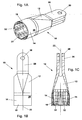
- the dimensionally stable component element 12 may, for example, fork-shaped at one, namely its other, end 28, which faces away from the end 18 of the dimensionally stable component element 12 and thus also the end 20 of the hollow-profiled component element 16 and with a Anschlußelence 30 in the form of be equipped, for example, a joint eye, condyle or the like.
- elevations 32 are provided in the hollow-profiled section 14 of the dimensionally stable component element 12.
- the elevations 32 extend at or over the inner circumference 24 radially inwards toward the longitudinal axis 22 of the dimensionally stable component element 12 and the hollow-profiled component element 16.
- a plurality of elevations 32 is provided.
- the elevations 32 are substantially elongated, elongated, bead-like, finger-shaped or wedge-shaped.
- the elevations 32 as in the embodiment of Fig. 1A to 1C represented, over the inner circumference 24 of the hollow profiled portion 14 of the dimensionally stable component member 12 to each other uniformly spaced.
- the surveys 32 continue to be provided with continuous transitions to the / the adjacent or adjacent thereto area / s. With others Words go the surveys 32 steadily, ie “soft” or “supple”, in the / adjacent or adjacent thereto area / e over or run to the extent. Edged, angular or sharp transitions, which can quickly lead to damage of the fiber-reinforced plastic and thus to a failure of the entire component element 12, are excluded.
- elevations 32 are provided by way of example.
- the elevations 32 are elongate and arranged at an angle ⁇ ⁇ to the longitudinal axis 22 of the dimensionally stable component element 12 and the hollow-profiled component element 16. Due to the arrangement of the elevations 32 at an angle ⁇ ⁇ tensile, compressive and torsional forces can be transmitted.
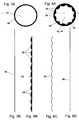
- FIGS. 3A and 3B and FIGS. 4A to 4D further illustrate the construction of the component 10 according to the invention.
- Figs. 3A to 4D For example, a cross section through the hollow profiled portion 14 of the dimensionally stable component element 12 and the hollow-profiled component element 16 comparable to the line IVA-IVA in the Fig. 2 underlie.
- the hollow profiled component element 16 is shown schematically in cross section.
- the resulting outer circumference 26 is in the Fig. 3B unwound and gives the length 34.
- the dimensionally stable component element 12 in the region of the hollow profiled portion 14 is shown schematically in cross section.
- On the inner circumference 24 of the section 14 a total of eleven elevations 32 are arranged evenly distributed.
- the resulting inner circumference 24 is in the Fig. 4B handled together with the elevations 32.
- the resulting inner circumference 24 is in the Fig. 4C unwound without the elevations 32 and results in longitudinal extension according to the Fig. 4D the length 36.
- the lengths 34 and 36 are the same, are in any case taking into account minor, but never excluded tolerance inaccuracies or tolerance deviations in the production essentially and thus approximately the same.
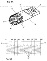
- Figs. 5A and 5B is a further embodiment of a component 10 according to the invention with a dimensionally stable component element 12 'shown.
- dimensionally stable component member 12 ' In the in the Figs. 5A and 5B shown embodiment of the dimensionally stable component member 12 'are raised portions 32' are provided, which extend radially inwardly, angled or meandering (not shown) and formed axially or parallel to the longitudinal axis 22 of the dimensionally stable component member 12 and the hollow-profiled component element 16 are arranged.
- the elevations 32 ' are twisted in opposite directions at an angle of 10 ° relative to the longitudinal axis 22, for example. Due to the angled formation of the elevations 32 'also tensile, compressive and torsional forces are transferable.
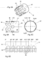
- FIGS. 6A to 6D is another embodiment of a component 10 according to the invention with a dimensionally stable component element 12 "proposed.
- recesses 38 recesses or openings can be equally a positive connection, as in the previously described embodiments of Fig. 1A to 1C and 5A, 5B on the basis of the elevations 32, 32 'realize, wherein the inner circumference 24 of the hollow profiled portion 14 of the dimensionally stable component member 12 "and the outer circumference 26 of the hollow-profiled component element 16 as it were consistent with each other or again at least substantially match.
- the recesses 38, recesses or openings extending radially outwards are likewise arranged uniformly spaced from one another via the inner circumference 24 of the hollow profiled section 14 of the dimensionally stable component element 12 " FIGS. 6A to 6D can be seen, the recesses 38, recesses or openings in this embodiment are circular. This also allows tensile, compressive and torsional forces to be transmitted.
- FIGS. 6A to 6D show further that two rows of recesses 38, recesses or openings are provided, which are additionally arranged offset on the inner circumference 24 to each other axially to the longitudinal axis 22 of the dimensionally stable component member 12 "and the hollow-profiled component element 16.
- FIGs. 7A and 7B is yet another embodiment of a component 10 according to the invention with a dimensionally stable component element 12 '' shown.
- Recesses 38 ' are elongate or in the form of an elongated hole and are arranged axially relative to the longitudinal axis 22 of the dimensionally stable component element 12'"and the hollow-profiled component element 16 , In this respect, tensile, compressive and torsional forces can equally be transmitted with this embodiment.
- a component 10 according to the invention with a dimensionally stable component element 12 "" in the form of a framework or a truss structure or for a truss or a framework structure are shown.
- a central node element 40, 40 ' is provided, from which in each case at least two, in this case a total of three, hollow-profiled component elements 16 are received and supported with their one end 20.
- the three hollow-profiled component elements 16 each extend approximately radially away from the associated node element 40, 40 'to the outside and open at the other end 42 in separate dimensionally stable component elements 12, 12', 12 ", 12"', 12 “” (not shown ).
- These component elements 12, 12 ', 12 ", 12"', 12 “” may be separate component elements 12, 12 ', 12 ", 12"', etc., or additional component elements 12 "", depending on the individual application purpose Node elements 40, 40 'act.
- the two embodiments of the component 10 after the Figs. 8A and 8B differ from each other only in the form of the node elements 40, 40 'of the component elements 12 "" to each other, in the shape of the cross section of the hollow-profiled component elements 16, which are once tubular and once square or octagonal configured, and in the angular arrangement of the component elements 12 ". to each other, ie with a regular division of 120 ° or with an irregular division of 100 °, 130 ° and 130 °.
- 1A to 8B presented embodiments, to design, for example, elongated, elongated, bead-like, finger-shaped, meandering, wedge-shaped, angled, circular, elliptical, elliptical, oval, triangular, quadrangular, square or rectangular, polygonal, trapezoidal, parallelogram or polygonal and / or form a combination thereof and / or axially and / or at an angle ⁇ ⁇ to the longitudinal axis 22 of the dimensionally stable component element 12, 12 ', 12 ", 12"', 12 “” and the hollow-profiled component element 16 to be arranged.
- the dimensionally stable component element 12, 12 ', 12 ", 12"', 12 “” and the hollow-profiled component element 16 expediently have an outer circumference 26 of the same shape and dimension. In any case, this applies at least partially to the dimensionally stable component element 12 for a region of its hollow profiled section 14.
- the dimensionally stable component element 12, 12 ', 12 ", 12"', 12 “” and / or the hollow-profiled component element 16 is / are lightweight construction and / or corrosion resistant.
- the dimensionally stable component element 12, 12 ', 12 ", 12"', 12 “” itself is formed of metal, in particular of steel, stainless steel, aluminum, titanium, an alloy thereof.
- the dimensionally stable component element 12 can alternatively or cumulatively be made of plastic, in particular polyimide (PI), polyoxymethylene (POM) or polytetrafluoroethylene (PTFE), without or with aluminum oxide, aluminum nitride, aramid, basalt, boron nitride, glass , Graphite, carbon, nylon, polyethylene, polyester, silicon carbide, silicon nitride and / or ceramic fiber reinforcement, and / or a combination thereof.
- PI polyimide
- POM polyoxymethylene
- PTFE polytetrafluoroethylene
- the dimensionally stable component element 12, 12 ', 12 ", 12"', 12 “” by milling, turning, grinding or the like surface treatment, casting or investment casting, drawing or deep drawing and / or, in particular subsequent, welding and / or a Combination produced.
- the hollow profiled component element 16 of fiber reinforced plastic itself is coated with aluminum oxide, aluminum nitride, aramid, basalt, boron nitride, glass, graphite, carbon, nylon, polyethylene, polyester, silicon carbide, silicon nitride and / or or ceramic fibers and / or a combination thereof.
- the hollow-profiled component element 16 may also be formed from fiber composite material.
- the hollow-profiled component element 16 of fiber-reinforced plastic can be produced by a prepreg process, wet impregnation process or resin transfer molding (RTM) process and / or a combination thereof or the like process for the production of fiber composite bodies.
- RTM resin transfer molding
- hollow-profiled component element 16 made of fiber-reinforced plastic in cross-section round, elliptical, elliptical, oval, triangular, square, square or rectangular, polygonal, trapezoidal, parallelogram or polygonal and / or formed as a combination thereof.
- the hollow-profiled component element 16 is partially pushed with the end 20 into the hollow-profiled section 14 of the dimensionally stable component element 12, 12 ', 12 ", 12"' at its end 18 and received by the hollow-profiled section 14 of the dimensionally stable component element 12.
- the hollow-profiled component element 16 Before the partial insertion or insertion with its end 20 into the hollow profiled section 14 of the dimensionally stable component element 12, 12 ', 12 ", 12", the hollow-profiled component element 16 is radially deformed. The hollow profiled component element 16 is still uncured at this time and so far flexible and deformable. During or through the radial deformation, the outer circumference 26 of the hollow-profiled component element 16 is / is temporarily smaller than the inner circumference 24, in particular as the elevations 32, 32 ', which are arranged on the inner circumference 24 and extend radially inwardly, of the dimensionally stable component element 12 in FIG Area of the hollow-shaped portion 14th
- the hollow-profiled component element 16 relaxes again slightly in the hollow-profiled section 14 of the dimensionally stable component element 12, 12 ', 12 ", 12"' and deforms back.
- the hollow-profiled component element 16 lies with its outer circumference 26 on the inner circumference 24 or on the projections 24, which are arranged on the inner circumference 24 and project radially inwardly toward the longitudinal axis 22, and / or recesses 38, 38 ', recesses or openings, extending radially outward from the longitudinal axis 22, the dimensionally stable component element 12, 12 ', 12 ", 12"' (light) to.
- an inflatable element (not shown), for example an inflatable tube, is introduced or introduced into the hollow-profiled component element 16.
- the inflatable element is inflated after its introduction into the hollow profiled component element 16.
- the hollow-profiled component element 16 of the inflatable element with its outer periphery 26 positively against the inner circumference 24 of the dimensionally stable component member 12, 12 ', 12 ", 12"' in the region of the hollow-shaped portion 14 (pressed) or pressed.
- the hollow-profiled component element 16 with its outer circumference 26 is positively connected to the inner circumference 24 and the elevations 32, 32 'and / or recesses 38, 38', recesses or openings of the dimensionally stable component element 12, on the inner circumference 24 in the region of the hollow portion 14 are arranged and extend radially inwards or outwards, (pressed).
- the inner circumference 24 of the hollow-profiled section 14 of the dimensionally stable component element 12, 12 ', 12 ", 12"' and the outer circumference 26 of the hollow-profiled component element 16 coincide with each other or at least substantially coincide.
- the molding or applying thus takes place without folding the hollow-profiled component element 16.
- the fibers of the hollow-profiled component element 16 are therefore not kinked, compressed, warped or otherwise subjected to constant loading.
- the hollow profiled component element 16 is pressurized by the inflatable element until it is fully cured.
- the hollow-profiled component element 16 of the inflatable element with a pressure of about 2 to about 10 bar, in particular from about 4 to about 8 bar, applied. Most preferably, a pressure of about 6 bar has been found in practice.
- the inflatable element After curing, the inflatable element is pulled out of the hollow profiled component elements 16 again and the component 10 is supplied to its processing or processing further provided.
- the invention is not limited to the illustrated embodiments of the component 10 according to the invention.
- a dimensionally stable component element in the form of a plug-in coupling (not shown) for the connection of two hollow-profiled component elements 16 made of fiber-reinforced plastic.
- the two hollow-profiled component elements 16 in turn are then each provided at their end facing away from the Einsteckkupplung with a dimensionally stable component member 12 which acts as a connection body with a connection element 30 in the form of a Gelenkauges, condyle or the like force and / or Momenteneintechnischs- or - appreciatedtragungsettis.
- the length of the component 10 according to the invention can be varied as desired.
- the component 10 or the dimensionally stable component element 12, 12 ', 12 “, 12"', 12 “” and / or the hollow-profiled component element 16 made of fiber-reinforced plastic , in particular wholly or partly, oblong, elongated, curved, meandering, undulating, serpentine, angled, (semi) circular, (semi) ellipsoidal, curved, curved and / or shaped as a combination thereof.
- component 10 or dimensionally stable component element 12, 12 ', 12 “, 12"', 12 “” and / or hollow-profiled component element 16 is arbitrary and individually adaptable to the respective use and function as well as the spatial specifications. Consequently, the component 10 or the dimensionally stable component element 12, 12 ', 12 ", 12", 12 "” and / or the hollow-profiled component element 16 can essentially axially over the entire length thereof or over a part thereof or axis-parallel extend and / or in any other, deviating manner have any other spatial forms.
- the component 10 or the dimensionally stable component element 12, 12 ', 12 ", 12"', 12 “” and / or the hollow-profiled component element 16 can / can be arranged in a single spatial plane or in several, in particular two or more three, spatial levels extend, either completely or partially.
- connection or connection element fitting, flange, plug-in coupling for the connection of at least one hollow-profiled component element 16 made of fiber-reinforced plastic, node element 40, 40 'for a framework or a framework structure or the same connection body, in particular with a joint eye, condyle or the like force introduction or -übertragungselement form.
- the radially inwardly extending elevations 32, 32 'and / or the radially outwardly extending recesses 38, 38', recesses or openings may be arbitrarily shaped, in particular, for example, elongated, elongated, bead-like, finger-shaped, meandering, wedge-shaped, angled, circular, elliptical, elliptical, oval, triangular, quadrangular, square or rectangular, polygonal, trapezoidal, parallelogram or polygonal, and / or formed as a combination thereof.
Landscapes
- Engineering & Computer Science (AREA)
- General Engineering & Computer Science (AREA)
- Mechanical Engineering (AREA)
- Ocean & Marine Engineering (AREA)
- Moulding By Coating Moulds (AREA)
- Prostheses (AREA)
- Pharmaceuticals Containing Other Organic And Inorganic Compounds (AREA)
Applications Claiming Priority (3)
| Application Number | Priority Date | Filing Date | Title |
|---|---|---|---|
| DE102011110288 | 2011-06-22 | ||
| DE102011053480A DE102011053480A1 (de) | 2011-06-22 | 2011-09-09 | Bauteil zur Aufnahme und/oder Übertragung von mechanischen Kräften und/oder Momenten, ein Verfahren zu dessen Herstellung und dessen Verwendung |
| PCT/EP2012/061715 WO2012175500A1 (de) | 2011-06-22 | 2012-06-19 | Bauteil zur aufnahme und/oder übertragung von mechanischen kräften und/oder momenten, ein verfahren zu dessen herstellung und dessen verwendung |
Publications (2)
| Publication Number | Publication Date |
|---|---|
| EP2724036A1 EP2724036A1 (de) | 2014-04-30 |
| EP2724036B1 true EP2724036B1 (de) | 2016-08-10 |
Family
ID=47321139
Family Applications (1)
| Application Number | Title | Priority Date | Filing Date |
|---|---|---|---|
| EP12745411.4A Active EP2724036B1 (de) | 2011-06-22 | 2012-06-19 | Bauteil zur aufnahme und/oder übertragung von mechanischen kräften und/oder momenten, ein verfahren zu dessen herstellung und dessen verwendung |
Country Status (12)
| Country | Link |
|---|---|
| US (2) | US9874240B2 (pl) |
| EP (1) | EP2724036B1 (pl) |
| BR (1) | BR112013033138B1 (pl) |
| CA (1) | CA2839996C (pl) |
| DE (1) | DE102011053480A1 (pl) |
| ES (1) | ES2598832T3 (pl) |
| HU (1) | HUE029436T2 (pl) |
| IL (1) | IL230015A (pl) |
| PL (1) | PL2724036T3 (pl) |
| PT (1) | PT2724036T (pl) |
| RU (1) | RU2596382C2 (pl) |
| WO (1) | WO2012175500A1 (pl) |
Families Citing this family (11)
| Publication number | Priority date | Publication date | Assignee | Title |
|---|---|---|---|---|
| DE102014104638A1 (de) * | 2014-04-02 | 2015-10-08 | Dr. Ing. H.C. F. Porsche Aktiengesellschaft | Verfahren zum Verbinden von Hohlprofilen |
| DE102014217372A1 (de) * | 2014-09-01 | 2016-03-03 | Bayerische Motoren Werke Aktiengesellschaft | Verfahren zum Herstellen eines lokal verstärkten Profilbauteils |
| BE1022119B1 (fr) | 2014-09-09 | 2016-02-17 | Bd Invent S.A. | Arbre de transmission et son procede de fabrication |
| DE102014222385A1 (de) | 2014-11-03 | 2016-05-04 | Bayerische Motoren Werke Aktiengesellschaft | Krafteinleitungsbauteil sowie Verfahren zur Herstellung von Composite- Rohrverbindungen mit einem Krafteinleitungsbauteil |
| US20170082137A1 (en) * | 2015-09-22 | 2017-03-23 | Rohr, Inc. | Driveshaft for a rotary system |
| US10344794B2 (en) * | 2016-11-18 | 2019-07-09 | Dana Automotive Systems Group, Llc | Open composite shaft |
| DE102017106878B4 (de) | 2017-03-30 | 2024-05-29 | Dr. Ing. H.C. F. Porsche Aktiengesellschaft | Anbindungsstruktur zur Anbindung eines faserverstärkten Kunststoffbauteils an ein Anbindungsbauteil und Anordnung eines faserverstärkten Kunststoffbauteils an mindestens einem Anbindungsbauteil |
| DE102018208282A1 (de) * | 2018-05-25 | 2019-11-28 | Zf Friedrichshafen Ag | Fahrwerklenker für ein Kraftfahrzeug |
| JP7148333B2 (ja) * | 2018-09-07 | 2022-10-05 | ナブテスコ株式会社 | 繊維含有複合材の接合 |
| US12253107B2 (en) * | 2019-01-15 | 2025-03-18 | Hamilton Sundstrand Corporation | Drive shafts with enhanced bending flexibility |
| CN114658747A (zh) * | 2021-04-29 | 2022-06-24 | 长城汽车股份有限公司 | 一种车用传动轴、制作方法及汽车 |
Citations (1)
| Publication number | Priority date | Publication date | Assignee | Title |
|---|---|---|---|---|
| DE202005010293U1 (de) * | 2005-06-30 | 2005-09-08 | Funck, Ralph, Dr. | Krafteinleitung für Faserverbundstreben in Flugzeugen |
Family Cites Families (9)
| Publication number | Priority date | Publication date | Assignee | Title |
|---|---|---|---|---|
| AT383319B (de) * | 1982-09-07 | 1987-06-25 | Fischer Gmbh | Rohrfoermiger hohlkoerper aus faserverstaerktem kunststoff, insbesondere strukturbauteil fuer ein fahrzeug, zur uebertragung von druck-,zug-,biege- und torsionskraeften |
| US5217555A (en) * | 1991-12-09 | 1993-06-08 | Lockheed Corporation | Process for making hollow tubular structural members with integral end attachment fittings |
| US5624519A (en) * | 1992-05-29 | 1997-04-29 | Trek Bicycle, Corp. | Method making a composite bicycle frame using composite lugs |
| RU2135880C1 (ru) * | 1996-11-14 | 1999-08-27 | Закрытое акционерное общество "ХОРСМАШ" | Устройство для соединения пластмассовых труб |
| FR2769866B1 (fr) | 1997-10-20 | 2000-01-14 | Sarma | Procede de moulage, moule de fabrication d'une piece globalement cylindrique a profil creux en matiere composite et piece obtenue grace a ce procede |
| DE102006056440A1 (de) * | 2006-11-28 | 2008-06-05 | Eads Deutschland Gmbh | Crash-Energieabsorber-Element, Anbindungselement mit einem solchen Crash-Engergieabsorber-Element, sowie Luftfahrzeug |
| US8414724B2 (en) * | 2006-12-02 | 2013-04-09 | The Boeing Company | Composite tube having cobonded end fittings and method of making same |
| DE102006058377B4 (de) | 2006-12-08 | 2010-09-16 | Airbus Deutschland Gmbh | Stange zur strukturellen Verstärkung einer Rumpfstruktur eines Flugzeugs |
| US8904904B2 (en) * | 2011-11-03 | 2014-12-09 | The Boeing Company | Tubular composite strut having internal stiffening |
-
2011
- 2011-09-09 DE DE102011053480A patent/DE102011053480A1/de not_active Withdrawn
-
2012
- 2012-06-19 ES ES12745411.4T patent/ES2598832T3/es active Active
- 2012-06-19 RU RU2013156860/11A patent/RU2596382C2/ru active
- 2012-06-19 US US14/127,615 patent/US9874240B2/en active Active
- 2012-06-19 EP EP12745411.4A patent/EP2724036B1/de active Active
- 2012-06-19 PL PL12745411T patent/PL2724036T3/pl unknown
- 2012-06-19 CA CA2839996A patent/CA2839996C/en active Active
- 2012-06-19 WO PCT/EP2012/061715 patent/WO2012175500A1/de not_active Ceased
- 2012-06-19 BR BR112013033138-0A patent/BR112013033138B1/pt active IP Right Grant
- 2012-06-19 HU HUE12745411A patent/HUE029436T2/hu unknown
- 2012-06-19 PT PT127454114T patent/PT2724036T/pt unknown
-
2013
- 2013-12-18 IL IL230015A patent/IL230015A/en active IP Right Grant
-
2018
- 2018-01-22 US US15/876,854 patent/US10247227B2/en active Active
Patent Citations (1)
| Publication number | Priority date | Publication date | Assignee | Title |
|---|---|---|---|---|
| DE202005010293U1 (de) * | 2005-06-30 | 2005-09-08 | Funck, Ralph, Dr. | Krafteinleitung für Faserverbundstreben in Flugzeugen |
Also Published As
| Publication number | Publication date |
|---|---|
| RU2013156860A (ru) | 2015-07-27 |
| DE102011053480A1 (de) | 2012-12-27 |
| PL2724036T3 (pl) | 2017-02-28 |
| BR112013033138B1 (pt) | 2021-04-20 |
| RU2596382C2 (ru) | 2016-09-10 |
| US10247227B2 (en) | 2019-04-02 |
| CA2839996A1 (en) | 2012-12-27 |
| IL230015A (en) | 2017-03-30 |
| PT2724036T (pt) | 2016-11-14 |
| US20140137700A1 (en) | 2014-05-22 |
| US20180142727A1 (en) | 2018-05-24 |
| EP2724036A1 (de) | 2014-04-30 |
| US9874240B2 (en) | 2018-01-23 |
| WO2012175500A1 (de) | 2012-12-27 |
| ES2598832T3 (es) | 2017-01-30 |
| CA2839996C (en) | 2017-06-06 |
| HUE029436T2 (hu) | 2017-02-28 |
| BR112013033138A2 (pt) | 2017-01-24 |
Similar Documents
| Publication | Publication Date | Title |
|---|---|---|
| EP2724036B1 (de) | Bauteil zur aufnahme und/oder übertragung von mechanischen kräften und/oder momenten, ein verfahren zu dessen herstellung und dessen verwendung | |
| EP3615357B1 (de) | Achsstrebe | |
| EP2419325B1 (de) | Spant und verfahren zur herstellung eines solchen spants | |
| DE102008032834B4 (de) | Omega-Stringer zum Versteifen eines flächigen Bauteils und Verfahren zum Herstellen eines Faserverbundbauteils für Schalensegmente | |
| DE102013007284A1 (de) | Verbindungsstrebe und Verfahren zur Herstellung derselben | |
| DE3228110C2 (de) | Torsionswelle | |
| DE102017130884B4 (de) | Luftfahrzeug und Verfahren zum Herstellen eines Luftfahrzeugs | |
| DE3113791A1 (de) | "rohrfoermiger hohlkoerper, verfahren zu seiner herstellung sowie vorrichtung zur durchfuehrung des verfahrens" | |
| EP3953602A1 (de) | Biegefederelement aus einem faserkunststoffverbundmaterial | |
| EP2999616B1 (de) | Achsträger eines fahrzeugs | |
| DE102013108065A1 (de) | Elastomerlager | |
| WO2019224018A1 (de) | Verfahren zum herstellen einer klebeverbindung sowie eine achstrebe für ein fahrzeug | |
| DE102013002365B3 (de) | Faserverstärkte Versteifungsstrebe, Herstellverfahren und Kraftfahrzeugkarosserie | |
| DE102013222016A1 (de) | Verfahren zum Herstellen eines verstärkten Faserverbundbauteils in Schalenbauweise | |
| EP4055297A1 (de) | Biegefederelement aus einem faserkunststoffverbundmaterial | |
| EP3557117B1 (de) | Druckbehälter sowie verfahren zur anbindung eines druckbehälters in eine karosseriestruktur | |
| WO2013107651A1 (de) | Knickstrebe für ein fahrwerk | |
| EP3237241B1 (de) | Verbund aus einem achslenker und einem achsrohr sowie verfahren zur herstellung eines an einem achsrohr festgelegten achslenkers. | |
| EP2700554A1 (de) | Vorrichtung zur freitragenden Befestigung eines Fahrgastsitzes und Verfahren zur Herstellung einer solchen Vorrichtung sowie Wagenkasten | |
| DE102014007750B4 (de) | Aufprallträger für ein Kraftfahrzeug | |
| WO2018146218A1 (de) | Verbindungselement zur anbindung eines bauteils an eine faserverbundstruktur | |
| DE102015112173B4 (de) | Verfahren zur Herstellung eines Anschlussteils für ein rohrförmiges Bauteil aus faserverstärktem Kunststoff | |
| DE102016206296B4 (de) | Verbindungssystem, Verbindungsanordnung und Verfahren | |
| DE102013215933A1 (de) | Strukturbauteil eines Fahrzeugs | |
| DE202013105458U1 (de) | Aushärtewerkzeug und Komponenten davon zum Aushärten von Prepreg Formen für Rotorblätter für Windkraftanlagen im Autoklaven |
Legal Events
| Date | Code | Title | Description |
|---|---|---|---|
| PUAI | Public reference made under article 153(3) epc to a published international application that has entered the european phase |
Free format text: ORIGINAL CODE: 0009012 |
|
| 17P | Request for examination filed |
Effective date: 20140114 |
|
| AK | Designated contracting states |
Kind code of ref document: A1 Designated state(s): AL AT BE BG CH CY CZ DE DK EE ES FI FR GB GR HR HU IE IS IT LI LT LU LV MC MK MT NL NO PL PT RO RS SE SI SK SM TR |
|
| DAX | Request for extension of the european patent (deleted) | ||
| 17Q | First examination report despatched |
Effective date: 20150427 |
|
| GRAP | Despatch of communication of intention to grant a patent |
Free format text: ORIGINAL CODE: EPIDOSNIGR1 |
|
| INTG | Intention to grant announced |
Effective date: 20160301 |
|
| GRAP | Despatch of communication of intention to grant a patent |
Free format text: ORIGINAL CODE: EPIDOSNIGR1 |
|
| GRAS | Grant fee paid |
Free format text: ORIGINAL CODE: EPIDOSNIGR3 |
|
| INTG | Intention to grant announced |
Effective date: 20160524 |
|
| GRAA | (expected) grant |
Free format text: ORIGINAL CODE: 0009210 |
|
| AK | Designated contracting states |
Kind code of ref document: B1 Designated state(s): AL AT BE BG CH CY CZ DE DK EE ES FI FR GB GR HR HU IE IS IT LI LT LU LV MC MK MT NL NO PL PT RO RS SE SI SK SM TR |
|
| REG | Reference to a national code |
Ref country code: GB Ref legal event code: FG4D Free format text: NOT ENGLISH |
|
| REG | Reference to a national code |
Ref country code: CH Ref legal event code: EP Ref country code: AT Ref legal event code: REF Ref document number: 819339 Country of ref document: AT Kind code of ref document: T Effective date: 20160815 |
|
| REG | Reference to a national code |
Ref country code: IE Ref legal event code: FG4D Free format text: LANGUAGE OF EP DOCUMENT: GERMAN |
|
| REG | Reference to a national code |
Ref country code: DE Ref legal event code: R096 Ref document number: 502012007919 Country of ref document: DE |
|
| REG | Reference to a national code |
Ref country code: CH Ref legal event code: NV Representative=s name: WAGNER + HELBIG PATENTANWAELTE CONSEILS EN PRO, CH |
|
| REG | Reference to a national code |
Ref country code: RO Ref legal event code: EPE |
|
| REG | Reference to a national code |
Ref country code: NL Ref legal event code: FP |
|
| REG | Reference to a national code |
Ref country code: SE Ref legal event code: TRGR |
|
| REG | Reference to a national code |
Ref country code: PT Ref legal event code: SC4A Ref document number: 2724036 Country of ref document: PT Date of ref document: 20161114 Kind code of ref document: T Free format text: AVAILABILITY OF NATIONAL TRANSLATION Effective date: 20161108 |
|
| REG | Reference to a national code |
Ref country code: LT Ref legal event code: MG4D |
|
| REG | Reference to a national code |
Ref country code: ES Ref legal event code: FG2A Ref document number: 2598832 Country of ref document: ES Kind code of ref document: T3 Effective date: 20170130 |
|
| PG25 | Lapsed in a contracting state [announced via postgrant information from national office to epo] |
Ref country code: IS Free format text: LAPSE BECAUSE OF FAILURE TO SUBMIT A TRANSLATION OF THE DESCRIPTION OR TO PAY THE FEE WITHIN THE PRESCRIBED TIME-LIMIT Effective date: 20161210 Ref country code: HR Free format text: LAPSE BECAUSE OF FAILURE TO SUBMIT A TRANSLATION OF THE DESCRIPTION OR TO PAY THE FEE WITHIN THE PRESCRIBED TIME-LIMIT Effective date: 20160810 Ref country code: NO Free format text: LAPSE BECAUSE OF FAILURE TO SUBMIT A TRANSLATION OF THE DESCRIPTION OR TO PAY THE FEE WITHIN THE PRESCRIBED TIME-LIMIT Effective date: 20161110 Ref country code: RS Free format text: LAPSE BECAUSE OF FAILURE TO SUBMIT A TRANSLATION OF THE DESCRIPTION OR TO PAY THE FEE WITHIN THE PRESCRIBED TIME-LIMIT Effective date: 20160810 Ref country code: FI Free format text: LAPSE BECAUSE OF FAILURE TO SUBMIT A TRANSLATION OF THE DESCRIPTION OR TO PAY THE FEE WITHIN THE PRESCRIBED TIME-LIMIT Effective date: 20160810 Ref country code: LT Free format text: LAPSE BECAUSE OF FAILURE TO SUBMIT A TRANSLATION OF THE DESCRIPTION OR TO PAY THE FEE WITHIN THE PRESCRIBED TIME-LIMIT Effective date: 20160810 |
|
| PG25 | Lapsed in a contracting state [announced via postgrant information from national office to epo] |
Ref country code: LV Free format text: LAPSE BECAUSE OF FAILURE TO SUBMIT A TRANSLATION OF THE DESCRIPTION OR TO PAY THE FEE WITHIN THE PRESCRIBED TIME-LIMIT Effective date: 20160810 Ref country code: GR Free format text: LAPSE BECAUSE OF FAILURE TO SUBMIT A TRANSLATION OF THE DESCRIPTION OR TO PAY THE FEE WITHIN THE PRESCRIBED TIME-LIMIT Effective date: 20161111 |
|
| REG | Reference to a national code |
Ref country code: HU Ref legal event code: AG4A Ref document number: E029436 Country of ref document: HU |
|
| REG | Reference to a national code |
Ref country code: SK Ref legal event code: T3 Ref document number: E 22522 Country of ref document: SK |
|
| PG25 | Lapsed in a contracting state [announced via postgrant information from national office to epo] |
Ref country code: EE Free format text: LAPSE BECAUSE OF FAILURE TO SUBMIT A TRANSLATION OF THE DESCRIPTION OR TO PAY THE FEE WITHIN THE PRESCRIBED TIME-LIMIT Effective date: 20160810 |
|
| REG | Reference to a national code |
Ref country code: DE Ref legal event code: R097 Ref document number: 502012007919 Country of ref document: DE |
|
| PG25 | Lapsed in a contracting state [announced via postgrant information from national office to epo] |
Ref country code: DK Free format text: LAPSE BECAUSE OF FAILURE TO SUBMIT A TRANSLATION OF THE DESCRIPTION OR TO PAY THE FEE WITHIN THE PRESCRIBED TIME-LIMIT Effective date: 20160810 Ref country code: SM Free format text: LAPSE BECAUSE OF FAILURE TO SUBMIT A TRANSLATION OF THE DESCRIPTION OR TO PAY THE FEE WITHIN THE PRESCRIBED TIME-LIMIT Effective date: 20160810 Ref country code: BG Free format text: LAPSE BECAUSE OF FAILURE TO SUBMIT A TRANSLATION OF THE DESCRIPTION OR TO PAY THE FEE WITHIN THE PRESCRIBED TIME-LIMIT Effective date: 20161110 |
|
| PLBE | No opposition filed within time limit |
Free format text: ORIGINAL CODE: 0009261 |
|
| STAA | Information on the status of an ep patent application or granted ep patent |
Free format text: STATUS: NO OPPOSITION FILED WITHIN TIME LIMIT |
|
| REG | Reference to a national code |
Ref country code: FR Ref legal event code: PLFP Year of fee payment: 6 |
|
| 26N | No opposition filed |
Effective date: 20170511 |
|
| PG25 | Lapsed in a contracting state [announced via postgrant information from national office to epo] |
Ref country code: SI Free format text: LAPSE BECAUSE OF FAILURE TO SUBMIT A TRANSLATION OF THE DESCRIPTION OR TO PAY THE FEE WITHIN THE PRESCRIBED TIME-LIMIT Effective date: 20160810 |
|
| PG25 | Lapsed in a contracting state [announced via postgrant information from national office to epo] |
Ref country code: MC Free format text: LAPSE BECAUSE OF FAILURE TO SUBMIT A TRANSLATION OF THE DESCRIPTION OR TO PAY THE FEE WITHIN THE PRESCRIBED TIME-LIMIT Effective date: 20160810 |
|
| REG | Reference to a national code |
Ref country code: IE Ref legal event code: MM4A |
|
| PG25 | Lapsed in a contracting state [announced via postgrant information from national office to epo] |
Ref country code: IE Free format text: LAPSE BECAUSE OF NON-PAYMENT OF DUE FEES Effective date: 20170619 Ref country code: LU Free format text: LAPSE BECAUSE OF NON-PAYMENT OF DUE FEES Effective date: 20170619 |
|
| REG | Reference to a national code |
Ref country code: BE Ref legal event code: MM Effective date: 20170630 |
|
| REG | Reference to a national code |
Ref country code: FR Ref legal event code: PLFP Year of fee payment: 7 |
|
| PG25 | Lapsed in a contracting state [announced via postgrant information from national office to epo] |
Ref country code: BE Free format text: LAPSE BECAUSE OF NON-PAYMENT OF DUE FEES Effective date: 20170630 |
|
| PG25 | Lapsed in a contracting state [announced via postgrant information from national office to epo] |
Ref country code: MT Free format text: LAPSE BECAUSE OF FAILURE TO SUBMIT A TRANSLATION OF THE DESCRIPTION OR TO PAY THE FEE WITHIN THE PRESCRIBED TIME-LIMIT Effective date: 20160810 |
|
| PG25 | Lapsed in a contracting state [announced via postgrant information from national office to epo] |
Ref country code: AL Free format text: LAPSE BECAUSE OF FAILURE TO SUBMIT A TRANSLATION OF THE DESCRIPTION OR TO PAY THE FEE WITHIN THE PRESCRIBED TIME-LIMIT Effective date: 20160810 |
|
| PG25 | Lapsed in a contracting state [announced via postgrant information from national office to epo] |
Ref country code: CY Free format text: LAPSE BECAUSE OF NON-PAYMENT OF DUE FEES Effective date: 20160810 |
|
| PG25 | Lapsed in a contracting state [announced via postgrant information from national office to epo] |
Ref country code: MK Free format text: LAPSE BECAUSE OF FAILURE TO SUBMIT A TRANSLATION OF THE DESCRIPTION OR TO PAY THE FEE WITHIN THE PRESCRIBED TIME-LIMIT Effective date: 20160810 |
|
| P01 | Opt-out of the competence of the unified patent court (upc) registered |
Effective date: 20230528 |
|
| PGFP | Annual fee paid to national office [announced via postgrant information from national office to epo] |
Ref country code: RO Payment date: 20230608 Year of fee payment: 12 Ref country code: PT Payment date: 20230609 Year of fee payment: 12 |
|
| PGFP | Annual fee paid to national office [announced via postgrant information from national office to epo] |
Ref country code: SK Payment date: 20230613 Year of fee payment: 12 Ref country code: PL Payment date: 20230612 Year of fee payment: 12 Ref country code: HU Payment date: 20230622 Year of fee payment: 12 |
|
| PGFP | Annual fee paid to national office [announced via postgrant information from national office to epo] |
Ref country code: GB Payment date: 20240620 Year of fee payment: 13 |
|
| PGFP | Annual fee paid to national office [announced via postgrant information from national office to epo] |
Ref country code: DE Payment date: 20240619 Year of fee payment: 13 |
|
| PGFP | Annual fee paid to national office [announced via postgrant information from national office to epo] |
Ref country code: CZ Payment date: 20240611 Year of fee payment: 13 Ref country code: AT Payment date: 20240620 Year of fee payment: 13 |
|
| PGFP | Annual fee paid to national office [announced via postgrant information from national office to epo] |
Ref country code: FR Payment date: 20240628 Year of fee payment: 13 |
|
| PGFP | Annual fee paid to national office [announced via postgrant information from national office to epo] |
Ref country code: TR Payment date: 20240610 Year of fee payment: 13 Ref country code: SE Payment date: 20240619 Year of fee payment: 13 |
|
| PGFP | Annual fee paid to national office [announced via postgrant information from national office to epo] |
Ref country code: IT Payment date: 20240625 Year of fee payment: 13 |
|
| PGFP | Annual fee paid to national office [announced via postgrant information from national office to epo] |
Ref country code: ES Payment date: 20240731 Year of fee payment: 13 Ref country code: CH Payment date: 20240701 Year of fee payment: 13 |
|
| PG25 | Lapsed in a contracting state [announced via postgrant information from national office to epo] |
Ref country code: PT Free format text: LAPSE BECAUSE OF NON-PAYMENT OF DUE FEES Effective date: 20241219 |
|
| PG25 | Lapsed in a contracting state [announced via postgrant information from national office to epo] |
Ref country code: RO Free format text: LAPSE BECAUSE OF NON-PAYMENT OF DUE FEES Effective date: 20240619 |
|
| REG | Reference to a national code |
Ref country code: SK Ref legal event code: MM4A Ref document number: E 22522 Country of ref document: SK Effective date: 20240619 |
|
| PG25 | Lapsed in a contracting state [announced via postgrant information from national office to epo] |
Ref country code: RO Free format text: LAPSE BECAUSE OF NON-PAYMENT OF DUE FEES Effective date: 20240619 Ref country code: PT Free format text: LAPSE BECAUSE OF NON-PAYMENT OF DUE FEES Effective date: 20241219 |
|
| PG25 | Lapsed in a contracting state [announced via postgrant information from national office to epo] |
Ref country code: HU Free format text: LAPSE BECAUSE OF NON-PAYMENT OF DUE FEES Effective date: 20240620 |
|
| PG25 | Lapsed in a contracting state [announced via postgrant information from national office to epo] |
Ref country code: SK Free format text: LAPSE BECAUSE OF NON-PAYMENT OF DUE FEES Effective date: 20240619 |
|
| PG25 | Lapsed in a contracting state [announced via postgrant information from national office to epo] |
Ref country code: PL Free format text: LAPSE BECAUSE OF NON-PAYMENT OF DUE FEES Effective date: 20240619 |
|
| PGFP | Annual fee paid to national office [announced via postgrant information from national office to epo] |
Ref country code: NL Payment date: 20251128 Year of fee payment: 14 |