EP2724036B1 - Component for absorbing and/or transmitting mechanical forces and/or moments, method for producing same and use thereof - Google Patents
Component for absorbing and/or transmitting mechanical forces and/or moments, method for producing same and use thereof Download PDFInfo
- Publication number
- EP2724036B1 EP2724036B1 EP12745411.4A EP12745411A EP2724036B1 EP 2724036 B1 EP2724036 B1 EP 2724036B1 EP 12745411 A EP12745411 A EP 12745411A EP 2724036 B1 EP2724036 B1 EP 2724036B1
- Authority
- EP
- European Patent Office
- Prior art keywords
- hollow
- component element
- profiled
- dimensionally stable
- component
- Prior art date
- Legal status (The legal status is an assumption and is not a legal conclusion. Google has not performed a legal analysis and makes no representation as to the accuracy of the status listed.)
- Active
Links
- 238000004519 manufacturing process Methods 0.000 title claims description 15
- 229920002430 Fibre-reinforced plastic Polymers 0.000 claims description 41
- 239000011151 fibre-reinforced plastic Substances 0.000 claims description 41
- 238000000034 method Methods 0.000 claims description 22
- -1 polytetrafluorethylene Polymers 0.000 claims description 17
- 239000000835 fiber Substances 0.000 claims description 15
- OKTJSMMVPCPJKN-UHFFFAOYSA-N Carbon Chemical compound [C] OKTJSMMVPCPJKN-UHFFFAOYSA-N 0.000 claims description 12
- 230000002787 reinforcement Effects 0.000 claims description 10
- 230000005540 biological transmission Effects 0.000 claims description 9
- 239000002131 composite material Substances 0.000 claims description 7
- 229910052582 BN Inorganic materials 0.000 claims description 6
- PZNSFCLAULLKQX-UHFFFAOYSA-N Boron nitride Chemical compound N#B PZNSFCLAULLKQX-UHFFFAOYSA-N 0.000 claims description 6
- 239000004677 Nylon Substances 0.000 claims description 6
- 239000004698 Polyethylene Substances 0.000 claims description 6
- 239000004642 Polyimide Substances 0.000 claims description 6
- 229910052581 Si3N4 Inorganic materials 0.000 claims description 6
- 239000004760 aramid Substances 0.000 claims description 6
- 229920003235 aromatic polyamide Polymers 0.000 claims description 6
- 229910052799 carbon Inorganic materials 0.000 claims description 6
- 239000000919 ceramic Substances 0.000 claims description 6
- PMHQVHHXPFUNSP-UHFFFAOYSA-M copper(1+);methylsulfanylmethane;bromide Chemical compound Br[Cu].CSC PMHQVHHXPFUNSP-UHFFFAOYSA-M 0.000 claims description 6
- 238000011161 development Methods 0.000 claims description 6
- 239000011521 glass Substances 0.000 claims description 6
- 229910002804 graphite Inorganic materials 0.000 claims description 6
- 239000010439 graphite Substances 0.000 claims description 6
- 229920001778 nylon Polymers 0.000 claims description 6
- 229920000728 polyester Polymers 0.000 claims description 6
- 229920000573 polyethylene Polymers 0.000 claims description 6
- 229920001721 polyimide Polymers 0.000 claims description 6
- 229920006324 polyoxymethylene Polymers 0.000 claims description 6
- 229920001343 polytetrafluoroethylene Polymers 0.000 claims description 6
- HBMJWWWQQXIZIP-UHFFFAOYSA-N silicon carbide Chemical compound [Si+]#[C-] HBMJWWWQQXIZIP-UHFFFAOYSA-N 0.000 claims description 6
- 229910010271 silicon carbide Inorganic materials 0.000 claims description 6
- HQVNEWCFYHHQES-UHFFFAOYSA-N silicon nitride Chemical compound N12[Si]34N5[Si]62N3[Si]51N64 HQVNEWCFYHHQES-UHFFFAOYSA-N 0.000 claims description 6
- 230000007704 transition Effects 0.000 claims description 5
- 238000010521 absorption reaction Methods 0.000 claims description 4
- 238000005266 casting Methods 0.000 claims description 4
- 230000008878 coupling Effects 0.000 claims description 4
- 238000010168 coupling process Methods 0.000 claims description 4
- 238000005859 coupling reaction Methods 0.000 claims description 4
- 238000000227 grinding Methods 0.000 claims description 4
- 229910052751 metal Inorganic materials 0.000 claims description 4
- 239000002184 metal Substances 0.000 claims description 4
- 238000003801 milling Methods 0.000 claims description 4
- TWNQGVIAIRXVLR-UHFFFAOYSA-N oxo(oxoalumanyloxy)alumane Chemical compound O=[Al]O[Al]=O TWNQGVIAIRXVLR-UHFFFAOYSA-N 0.000 claims description 4
- 230000000087 stabilizing effect Effects 0.000 claims description 4
- 238000004381 surface treatment Methods 0.000 claims description 4
- 238000007514 turning Methods 0.000 claims description 4
- 229910000831 Steel Inorganic materials 0.000 claims description 3
- RTAQQCXQSZGOHL-UHFFFAOYSA-N Titanium Chemical compound [Ti] RTAQQCXQSZGOHL-UHFFFAOYSA-N 0.000 claims description 3
- 239000000956 alloy Substances 0.000 claims description 3
- 229910045601 alloy Inorganic materials 0.000 claims description 3
- 229910052782 aluminium Inorganic materials 0.000 claims description 3
- XAGFODPZIPBFFR-UHFFFAOYSA-N aluminium Chemical compound [Al] XAGFODPZIPBFFR-UHFFFAOYSA-N 0.000 claims description 3
- 230000007797 corrosion Effects 0.000 claims description 3
- 238000005260 corrosion Methods 0.000 claims description 3
- 238000005470 impregnation Methods 0.000 claims description 3
- 229920003023 plastic Polymers 0.000 claims description 3
- 239000004033 plastic Substances 0.000 claims description 3
- 239000010935 stainless steel Substances 0.000 claims description 3
- 229910001220 stainless steel Inorganic materials 0.000 claims description 3
- 239000010959 steel Substances 0.000 claims description 3
- 229910052719 titanium Inorganic materials 0.000 claims description 3
- 239000010936 titanium Substances 0.000 claims description 3
- 238000003466 welding Methods 0.000 claims description 3
- 241000309551 Arthraxon hispidus Species 0.000 claims 2
- 230000006698 induction Effects 0.000 claims 1
- 238000003825 pressing Methods 0.000 claims 1
- 238000009745 resin transfer moulding Methods 0.000 claims 1
- 238000010276 construction Methods 0.000 description 7
- 238000013461 design Methods 0.000 description 5
- 238000003780 insertion Methods 0.000 description 5
- 230000037431 insertion Effects 0.000 description 5
- 229930040373 Paraformaldehyde Natural products 0.000 description 4
- 239000004810 polytetrafluoroethylene Substances 0.000 description 4
- 238000000465 moulding Methods 0.000 description 3
- WYTGDNHDOZPMIW-RCBQFDQVSA-N alstonine Natural products C1=CC2=C3C=CC=CC3=NC2=C2N1C[C@H]1[C@H](C)OC=C(C(=O)OC)[C@H]1C2 WYTGDNHDOZPMIW-RCBQFDQVSA-N 0.000 description 2
- PNEYBMLMFCGWSK-UHFFFAOYSA-N aluminium oxide Inorganic materials [O-2].[O-2].[O-2].[Al+3].[Al+3] PNEYBMLMFCGWSK-UHFFFAOYSA-N 0.000 description 2
- 230000001186 cumulative effect Effects 0.000 description 2
- 230000000694 effects Effects 0.000 description 2
- 238000005495 investment casting Methods 0.000 description 2
- 238000012545 processing Methods 0.000 description 2
- 239000011347 resin Substances 0.000 description 2
- 229920005989 resin Polymers 0.000 description 2
- 230000006641 stabilisation Effects 0.000 description 2
- 238000011105 stabilization Methods 0.000 description 2
- 238000001721 transfer moulding Methods 0.000 description 2
- 230000015572 biosynthetic process Effects 0.000 description 1
- 230000001788 irregular Effects 0.000 description 1
- 238000003754 machining Methods 0.000 description 1
- 229920000642 polymer Polymers 0.000 description 1
- 230000002028 premature Effects 0.000 description 1
- 238000012549 training Methods 0.000 description 1
- 238000012546 transfer Methods 0.000 description 1
Images


Classifications
-
- F—MECHANICAL ENGINEERING; LIGHTING; HEATING; WEAPONS; BLASTING
- F16—ENGINEERING ELEMENTS AND UNITS; GENERAL MEASURES FOR PRODUCING AND MAINTAINING EFFECTIVE FUNCTIONING OF MACHINES OR INSTALLATIONS; THERMAL INSULATION IN GENERAL
- F16C—SHAFTS; FLEXIBLE SHAFTS; ELEMENTS OR CRANKSHAFT MECHANISMS; ROTARY BODIES OTHER THAN GEARING ELEMENTS; BEARINGS
- F16C7/00—Connecting-rods or like links pivoted at both ends; Construction of connecting-rod heads
- F16C7/02—Constructions of connecting-rods with constant length
- F16C7/026—Constructions of connecting-rods with constant length made of fibre reinforced resin
-
- F—MECHANICAL ENGINEERING; LIGHTING; HEATING; WEAPONS; BLASTING
- F16—ENGINEERING ELEMENTS AND UNITS; GENERAL MEASURES FOR PRODUCING AND MAINTAINING EFFECTIVE FUNCTIONING OF MACHINES OR INSTALLATIONS; THERMAL INSULATION IN GENERAL
- F16C—SHAFTS; FLEXIBLE SHAFTS; ELEMENTS OR CRANKSHAFT MECHANISMS; ROTARY BODIES OTHER THAN GEARING ELEMENTS; BEARINGS
- F16C3/00—Shafts; Axles; Cranks; Eccentrics
- F16C3/02—Shafts; Axles
- F16C3/026—Shafts made of fibre reinforced resin
-
- Y—GENERAL TAGGING OF NEW TECHNOLOGICAL DEVELOPMENTS; GENERAL TAGGING OF CROSS-SECTIONAL TECHNOLOGIES SPANNING OVER SEVERAL SECTIONS OF THE IPC; TECHNICAL SUBJECTS COVERED BY FORMER USPC CROSS-REFERENCE ART COLLECTIONS [XRACs] AND DIGESTS
- Y10—TECHNICAL SUBJECTS COVERED BY FORMER USPC
- Y10T—TECHNICAL SUBJECTS COVERED BY FORMER US CLASSIFICATION
- Y10T29/00—Metal working
- Y10T29/49—Method of mechanical manufacture
- Y10T29/49826—Assembling or joining
- Y10T29/49945—Assembling or joining by driven force fit
-
- Y—GENERAL TAGGING OF NEW TECHNOLOGICAL DEVELOPMENTS; GENERAL TAGGING OF CROSS-SECTIONAL TECHNOLOGIES SPANNING OVER SEVERAL SECTIONS OF THE IPC; TECHNICAL SUBJECTS COVERED BY FORMER USPC CROSS-REFERENCE ART COLLECTIONS [XRACs] AND DIGESTS
- Y10—TECHNICAL SUBJECTS COVERED BY FORMER USPC
- Y10T—TECHNICAL SUBJECTS COVERED BY FORMER US CLASSIFICATION
- Y10T74/00—Machine element or mechanism
- Y10T74/21—Elements
- Y10T74/2142—Pitmans and connecting rods
Definitions
- the present invention relates to a component for receiving and / or transmitting mechanical forces and / or moments, a method for its production and its use.
- Such components are well known. Only exemplary is the DE 10 2006 058 377 B4 referred to, which is directed to a rod for structural reinforcement of a fuselage structure of an aircraft, which is formed from two end-mounted, dimensionally stable component elements and a hollow-profiled component element made of fiber-reinforced plastic, which is bordered by the two dimensionally stable component elements.
- such components have all proved to be consistently disadvantageous, since their design is often complex, not sufficiently dimensionally stable and relatively high weight, at the same time can not absorb and transmit high forces and / or moments, with concomitant no satisfactory strength and Have stiffness values. In addition, their life is usually not very high and their production are very costly.
- the document DE 20 2005 010 293 V1 discloses a force introduction element on struts made of fiber composite material.
- the present invention is therefore based on the object to provide a component for receiving and / or transmission of mechanical forces and / or moments available, with which can be prevented the above disadvantages, which therefore structurally particularly simple, at the same time compact and dimensionally stable and very is light-weight construction, allows transmission of high forces and moments, concomitantly has a very high strength and rigidity, and has a long life and is extremely inexpensive to manufacture, and to provide a method for its production and use thereof.
- the component according to the invention for receiving and / or transmitting mechanical forces and / or moments comprising at least one dimensionally stable component element with at least one hollow profiled section and at least one hollow profiled component element made of fiber-reinforced plastic, which can be partially absorbed by the hollow profiled portion of the dimensionally stable component element and in The hollow profiled portion of the dimensionally stable component element via radially inwardly extending projections and / or radially outwardly extending recesses, recesses or openings is positively arranged, wherein the inner circumference of the hollow profiled portion of the dimensionally stable component element and the outer periphery of the hollow-profiled component element of fiber-reinforced plastic match each other or - as a result of never completely exclude tolerance deviations in the production - at least substantially coincide timmen, a particularly simple, also compact and dimensionally stable construction of the component of relatively low weight is achieved.
- the component according to the invention has a very high strength and rigidity. Due to the fact that the inner circumference of the hollow profiled section of the dimensionally stable component element and the outer circumference of the hollow profiled component element made of fiber-reinforced plastic coincide with each other or at least substantially coincide, a direction-oriented deformation of the fibers of the hollow profiled component element made of fiber-reinforced plastic is ensured.
- the molding or applying takes place without any wrinkling, since the inner circumference of the hollow profiled portion of the dimensionally stable component element and the outer circumference of the hollow profiled component element the same, at least substantially, ie largely or largely the same is.
- the fibers of the hollow-profiled component element made of fiber-reinforced plastic are thus not kinked, compressed, warped or otherwise subjected to constant loading.
- a positive connection between the at least one dimensionally stable component element and the at least one hollow-profiled component element made of fiber-reinforced plastic is obtained as a result of the construction of the component according to the invention.
- the production of the component according to the invention is extremely simple and less labor-intensive and is therefore extremely inexpensive.
- the projections, which extend radially inwardly, and / or the recesses, recesses or openings, which extend radially outwardly, advantageously arranged uniformly spaced from one another over the inner circumference of the hollow profiled portion of the dimensionally stable component element ,
- the radially inwardly extending elevations and / or the radially outwardly extending recesses, recesses or openings according to claim 3 are elongate, elongated, bead-like, finger-shaped, meandering, wedge-shaped, angled, circular, elliptical, elliptical, oval , triangular, quadrangular, square or rectangular, polygonal, trapezoidal, parallelogram or polygonal and / or formed as a combination thereof, whereby tensile, compressive and torsional forces absorb, initiate and transfer equally.
- the radially inwardly extending projections and / or radially outwardly extending recesses, recesses or openings are arranged axially and / or at an angle to the longitudinal axis of the dimensionally stable component element and the hollow-profiled component element. In this way, tensile, compressive and also torsional forces can be transmitted by the component according to the invention.
- the elevations and / or depressions, recesses or openings are preferably equipped with continuous transitions to / into the adjacent area (s).
- the bumps and / or depressions, recesses or breakthroughs are continuous, i. "soft” or "supple", in the / the adjacent or adjacent thereto area / e over or run out so far. Edged, angular or sharp transitions, which can quickly lead to damage of the fiber-reinforced plastic and thus to a failure of the entire component element, are avoided.
- the dimensionally stable component element at least partially, in particular in a region of the hollow-profiled section, and the hollow-profiled component element according to claim 8, an outer periphery of the same shape and dimension.
- the dimensionally stable component element and / or the hollow-profiled component element according to claim 9 formed lightweight construction and / or corrosion resistant / are.
- the dimensionally stable component element according to claim 10 made of metal, in particular steel, stainless steel, aluminum, titanium, an alloy thereof and / or plastic, in particular polyimide (PI), polyoxymethylene (POM) or polytetrafluoroethylene (PTFE), with or without Alumina, aluminum nitride, aramid, basalt, boron nitride, glass, graphite, carbon, nylon, polyethylene, polyester, silicon carbide, silicon nitride and / or ceramic fiber reinforcement, and / or a combination thereof ,
- PI polyimide
- POM polyoxymethylene
- PTFE polytetrafluoroethylene
- the dimensionally stable component element by milling, turning, grinding or the like surface treatment, casting or investment casting, pulling or deep drawing and / or, in particular subsequent, welding and / or a combination thereof can be produced.
- the invention provides that the dimensionally stable component element according to claim 12 as a connection or connecting element, fitting, flange, Einsteckkupplung for the connection of at least one hollow-profiled component element made of fiber-reinforced plastic, node element for a Truss or a truss structure or the like connecting body, in particular with a joint eye, condyle or the like force and / or Momentenein suddenlys- or -übertragungselement is formed.
- the hollow-profile fiber-reinforced plastic structural member of claim 13 is comprised of alumina, aluminum nitride, aramid, basalt, boron nitride, glass, graphite, carbon, nylon, polyethylene, polyester, silicon carbide, silicon nitride and / or ceramic fibers and / or a combination thereof reinforced and / or formed from fiber composite material.
- hollow-profiled fiber-reinforced plastic component element according to claim 14 by a prepreg process, wet impregnation process or Resin Transfer Molding (RTM) method and / or a combination thereof or the like process for the production of fiber composites can be produced.
- RTM Resin Transfer Molding
- the hollow-profiled component element made of fiber-reinforced plastic in cross-section is preferably round, elliptical, elliptical, oval, triangular, quadrangular, square or rectangular, polygonal, trapezoidal, parallelogram or polygonal and / or formed as a combination thereof.
- the dimensionally stable component element and / or the hollow-profiled component element of fiber-reinforced plastic in particular completely or partially, oblong, elongated, curved, meander-shaped, wavy, serpentine, angled, (semi-) circular, (semi-circular) elliptical, curved, curved and / or shaped as a combination thereof.
- the dimensionally stable component element and / or the hollow-profiled component element can extend over its entire length or over part of it substantially axially or axially parallel and / or in any other deviating manner as desired have other spatial forms.
- the invention provides that the dimensionally stable component element and / or the hollow-profiled component element made of fiber-reinforced plastic according to claim 17, in particular completely or partially, is arranged in at least one spatial plane / are.
- the dimensionally stable component element and / or the hollow-profiled component element can extend completely or partially in a single spatial plane or in a plurality, in particular in two or three, spatial planes.
- the method according to the invention for producing a component for receiving and / or transmitting mechanical forces and / or moments comprising at least one dimensionally stable component element with a hollow profiled section and at least one hollow profiled component element made of fiber-reinforced plastic, wherein the at least one hollow-profiled component element made of fiber-reinforced plastic partially pushed into one end in the hollow profiled portion of the dimensionally stable component element and is received by the hollow profiled portion of the dimensionally stable component element and then by an inserted into the hollow profiled component element made of fiber reinforced plastic inflatable element with its outer circumference form-fit to the inner periphery of the dimensionally stable component element in the region of hollow-shaped portion (on) is pressed by the inflatable element after introduction into the hollow profiled Baut
- the method according to the invention is extremely simple, less labor-intensive and, above all, cost-effective Handling overall proved to be particularly
- the hollow profiled component element is radially deformed before the partial insertion of the end in the hollow profiled portion of the dimensionally stable component element, such that the outer periphery of the hollow profiled component element is smaller than the inner circumference, in particular arranged on the inner circumference, itself radially inwardly extending elevations, the dimensionally stable component element in the region of the hollow-shaped portion is.
- the hollow-profiled component element according to claim 20 with its outer circumference form fit to the inner circumference and on the inner circumference, radially inwardly extending elevations and / or radially outwardly extending recesses, recesses or openings of the dimensionally stable component element in the area from the hollow-shaped portion (an-) pressed, wherein the inner circumference of the hollow-profiled portion of the dimensionally stable component element and the outer circumference of the hollow-profiled component element coincide with each other or at least substantially coincide.
- the hollow profiled component element is pressurized by the inflatable element until its complete curing.
- the hollow profiled component element according to claim 22 of the inflatable element is preferably at a pressure of about 2 to about 10 bar, in particular of about 4 to about 8 bar, preferably from about 6 bar, applied.
- the component according to the invention in a very advantageous manner in vehicles, especially in aircraft or aircraft of aerospace, preferably in aircraft and spacecraft, especially in watercraft, preferably in a submarine or hovercraft (hovercraft), or in particular Land vehicles, preferably in a passenger car, passenger car, such as a bus or minibus, truck or RV, use.
- vehicles especially in aircraft or aircraft of aerospace, preferably in aircraft and spacecraft, especially in watercraft, preferably in a submarine or hovercraft (hovercraft), or in particular Land vehicles, preferably in a passenger car, passenger car, such as a bus or minibus, truck or RV, use.
- the component according to the invention is particularly suitable for receiving and / or transmitting mechanical forces and / or moments and in particular struts transmitting mechanical and compressive forces and / or torsional forces and / or tubular or rod-shaped connecting elements and / or trusses or Truss structures and / or drive shafts, preferably with at least one or more terminally arranged connection elements, joint eyes, condyle or the like Krafteintechnischs- or - appreciatedtragungsettin, in vehicles, most preferably in aircraft and spacecraft as support or stabilization struts for structural reinforcement of a fuselage structure and in land vehicles as support or stabilizing struts for the structural reinforcement of a body structure.
- the component 10 according to the invention is in vehicles, in particular in aircraft or aeronautical aircraft, preferably in aircraft and spacecraft, in particular in watercraft, preferably in a submarine or hovercraft, or in particular in land vehicles, preferably in a passenger car, passenger car, such as a bus or minibus, truck or RV provided.
- the component 10 according to the invention is particularly suitable for receiving and / or transmitting mechanical forces and / or moments and in particular as mechanical tensile and compressive forces and / or torsional forces transmitted struts and / or tubular or rod-shaped connecting elements and / or trusses or truss structures and / or drive shafts, preferably with at least one or more terminally arranged connection elements, joint eyes, condyle or the like force introduction or transmission elements, in vehicles, most preferably in aircraft and spacecraft as support or stabilizing struts for structural reinforcement of a fuselage structure and in land vehicles as support - or stabilization struts for structural reinforcement of a body structure.
- An inventively designed component 10 comprises at least one dimensionally stable component element 12, 12 ', 12 ", 12"', 12 “” with at least one hollow profiled portion 14 and at least one hollow profiled component element 16 made of fiber-reinforced plastic (see. Figs. 7A to 8B ).
- the hollow-profiled component element 16 in each case has a hollow-cylindrical or approximately wood-cylindrical shape.
- At least two dimensionally stable component elements 12, 12 ', 12 ", 12"', 12 “” are provided, each with at least one hollow profiled portion 14 and a hollow-profiled component element 16 made of fiber-reinforced plastic.
- the hollow-profiled component element 16 is arranged between the two dimensionally stable component elements 12.
- the component 10 according to the invention is designed, for example, as a hybrid strut or as a hybrid framework (structure).
- the hollow-profiled component element 16 is partially receivable by the hollow-profiled section 14 of the dimensionally stable component element 12, 12 ', 12 ", 12"', 12 "".
- One end 18 of the dimensionally stable component element 12, 12 ', 12 “, 12"', 12 “” and one end 20 of the hollow profiled component element 12, which the end 18 of the dimensionally stable component element 12, 12 ', 12 ", 12"', 12 “” facing, are thereby inserted into each other on the longitudinal axis 22 and pushed into each other.
- the inner circumference 24 of the hollow profiled section 14 of the dimensionally stable component element 12, 12 ', 12 ", 12"', 12 “” or a part thereof and the outer periphery 26 of the hollow-profiled component element 16 come to mutual contact.
- the hollow-profiled component element 16 can be arranged in a form-fitting manner in the hollow-profiled section 14 of the dimensionally stable component element 12, 12 ', 12 ", 12"', 12 "".
- the inner circumference 24 of the hollow profiled portion 14 of the dimensionally stable component element 12, 12 ', 12 ", 12"', 12 “” and the outer circumference 26 of the hollow profiled component element 16 are identical to each other, at least substantially identical, i. correspond to each other in shape and dimensions.
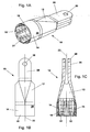
- the dimensionally stable component element 12 is used as connection or connection element, Fitting, flange, plug-in coupling for the connection of at least one hollow-profiled component element 16 made of fiber-reinforced plastic or the like connecting body or the like force and / or Momentenein foundeds- or -übertragungselement provided and designed accordingly.
- the dimensionally stable component element 12 may, for example, fork-shaped at one, namely its other, end 28, which faces away from the end 18 of the dimensionally stable component element 12 and thus also the end 20 of the hollow-profiled component element 16 and with a Anschlußelence 30 in the form of be equipped, for example, a joint eye, condyle or the like.
- elevations 32 are provided in the hollow-profiled section 14 of the dimensionally stable component element 12.
- the elevations 32 extend at or over the inner circumference 24 radially inwards toward the longitudinal axis 22 of the dimensionally stable component element 12 and the hollow-profiled component element 16.
- a plurality of elevations 32 is provided.
- the elevations 32 are substantially elongated, elongated, bead-like, finger-shaped or wedge-shaped.
- the elevations 32 as in the embodiment of Fig. 1A to 1C represented, over the inner circumference 24 of the hollow profiled portion 14 of the dimensionally stable component member 12 to each other uniformly spaced.
- the surveys 32 continue to be provided with continuous transitions to the / the adjacent or adjacent thereto area / s. With others Words go the surveys 32 steadily, ie “soft” or “supple”, in the / adjacent or adjacent thereto area / e over or run to the extent. Edged, angular or sharp transitions, which can quickly lead to damage of the fiber-reinforced plastic and thus to a failure of the entire component element 12, are excluded.
- elevations 32 are provided by way of example.
- the elevations 32 are elongate and arranged at an angle ⁇ ⁇ to the longitudinal axis 22 of the dimensionally stable component element 12 and the hollow-profiled component element 16. Due to the arrangement of the elevations 32 at an angle ⁇ ⁇ tensile, compressive and torsional forces can be transmitted.
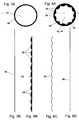
- FIGS. 3A and 3B and FIGS. 4A to 4D further illustrate the construction of the component 10 according to the invention.
- Figs. 3A to 4D For example, a cross section through the hollow profiled portion 14 of the dimensionally stable component element 12 and the hollow-profiled component element 16 comparable to the line IVA-IVA in the Fig. 2 underlie.
- the hollow profiled component element 16 is shown schematically in cross section.
- the resulting outer circumference 26 is in the Fig. 3B unwound and gives the length 34.
- the dimensionally stable component element 12 in the region of the hollow profiled portion 14 is shown schematically in cross section.
- On the inner circumference 24 of the section 14 a total of eleven elevations 32 are arranged evenly distributed.
- the resulting inner circumference 24 is in the Fig. 4B handled together with the elevations 32.
- the resulting inner circumference 24 is in the Fig. 4C unwound without the elevations 32 and results in longitudinal extension according to the Fig. 4D the length 36.
- the lengths 34 and 36 are the same, are in any case taking into account minor, but never excluded tolerance inaccuracies or tolerance deviations in the production essentially and thus approximately the same.
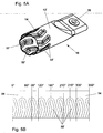
- Figs. 5A and 5B is a further embodiment of a component 10 according to the invention with a dimensionally stable component element 12 'shown.
- dimensionally stable component member 12 ' In the in the Figs. 5A and 5B shown embodiment of the dimensionally stable component member 12 'are raised portions 32' are provided, which extend radially inwardly, angled or meandering (not shown) and formed axially or parallel to the longitudinal axis 22 of the dimensionally stable component member 12 and the hollow-profiled component element 16 are arranged.
- the elevations 32 ' are twisted in opposite directions at an angle of 10 ° relative to the longitudinal axis 22, for example. Due to the angled formation of the elevations 32 'also tensile, compressive and torsional forces are transferable.
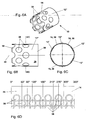
- FIGS. 6A to 6D is another embodiment of a component 10 according to the invention with a dimensionally stable component element 12 "proposed.
- recesses 38 recesses or openings can be equally a positive connection, as in the previously described embodiments of Fig. 1A to 1C and 5A, 5B on the basis of the elevations 32, 32 'realize, wherein the inner circumference 24 of the hollow profiled portion 14 of the dimensionally stable component member 12 "and the outer circumference 26 of the hollow-profiled component element 16 as it were consistent with each other or again at least substantially match.
- the recesses 38, recesses or openings extending radially outwards are likewise arranged uniformly spaced from one another via the inner circumference 24 of the hollow profiled section 14 of the dimensionally stable component element 12 " FIGS. 6A to 6D can be seen, the recesses 38, recesses or openings in this embodiment are circular. This also allows tensile, compressive and torsional forces to be transmitted.
- FIGS. 6A to 6D show further that two rows of recesses 38, recesses or openings are provided, which are additionally arranged offset on the inner circumference 24 to each other axially to the longitudinal axis 22 of the dimensionally stable component member 12 "and the hollow-profiled component element 16.
- FIGs. 7A and 7B is yet another embodiment of a component 10 according to the invention with a dimensionally stable component element 12 '' shown.
- Recesses 38 ' are elongate or in the form of an elongated hole and are arranged axially relative to the longitudinal axis 22 of the dimensionally stable component element 12'"and the hollow-profiled component element 16 , In this respect, tensile, compressive and torsional forces can equally be transmitted with this embodiment.
- a component 10 according to the invention with a dimensionally stable component element 12 "" in the form of a framework or a truss structure or for a truss or a framework structure are shown.
- a central node element 40, 40 ' is provided, from which in each case at least two, in this case a total of three, hollow-profiled component elements 16 are received and supported with their one end 20.
- the three hollow-profiled component elements 16 each extend approximately radially away from the associated node element 40, 40 'to the outside and open at the other end 42 in separate dimensionally stable component elements 12, 12', 12 ", 12"', 12 “” (not shown ).
- These component elements 12, 12 ', 12 ", 12"', 12 “” may be separate component elements 12, 12 ', 12 ", 12"', etc., or additional component elements 12 "", depending on the individual application purpose Node elements 40, 40 'act.
- the two embodiments of the component 10 after the Figs. 8A and 8B differ from each other only in the form of the node elements 40, 40 'of the component elements 12 "" to each other, in the shape of the cross section of the hollow-profiled component elements 16, which are once tubular and once square or octagonal configured, and in the angular arrangement of the component elements 12 ". to each other, ie with a regular division of 120 ° or with an irregular division of 100 °, 130 ° and 130 °.
- 1A to 8B presented embodiments, to design, for example, elongated, elongated, bead-like, finger-shaped, meandering, wedge-shaped, angled, circular, elliptical, elliptical, oval, triangular, quadrangular, square or rectangular, polygonal, trapezoidal, parallelogram or polygonal and / or form a combination thereof and / or axially and / or at an angle ⁇ ⁇ to the longitudinal axis 22 of the dimensionally stable component element 12, 12 ', 12 ", 12"', 12 “” and the hollow-profiled component element 16 to be arranged.
- the dimensionally stable component element 12, 12 ', 12 ", 12"', 12 “” and the hollow-profiled component element 16 expediently have an outer circumference 26 of the same shape and dimension. In any case, this applies at least partially to the dimensionally stable component element 12 for a region of its hollow profiled section 14.
- the dimensionally stable component element 12, 12 ', 12 ", 12"', 12 “” and / or the hollow-profiled component element 16 is / are lightweight construction and / or corrosion resistant.
- the dimensionally stable component element 12, 12 ', 12 ", 12"', 12 “” itself is formed of metal, in particular of steel, stainless steel, aluminum, titanium, an alloy thereof.
- the dimensionally stable component element 12 can alternatively or cumulatively be made of plastic, in particular polyimide (PI), polyoxymethylene (POM) or polytetrafluoroethylene (PTFE), without or with aluminum oxide, aluminum nitride, aramid, basalt, boron nitride, glass , Graphite, carbon, nylon, polyethylene, polyester, silicon carbide, silicon nitride and / or ceramic fiber reinforcement, and / or a combination thereof.
- PI polyimide
- POM polyoxymethylene
- PTFE polytetrafluoroethylene
- the dimensionally stable component element 12, 12 ', 12 ", 12"', 12 “” by milling, turning, grinding or the like surface treatment, casting or investment casting, drawing or deep drawing and / or, in particular subsequent, welding and / or a Combination produced.
- the hollow profiled component element 16 of fiber reinforced plastic itself is coated with aluminum oxide, aluminum nitride, aramid, basalt, boron nitride, glass, graphite, carbon, nylon, polyethylene, polyester, silicon carbide, silicon nitride and / or or ceramic fibers and / or a combination thereof.
- the hollow-profiled component element 16 may also be formed from fiber composite material.
- the hollow-profiled component element 16 of fiber-reinforced plastic can be produced by a prepreg process, wet impregnation process or resin transfer molding (RTM) process and / or a combination thereof or the like process for the production of fiber composite bodies.
- RTM resin transfer molding
- hollow-profiled component element 16 made of fiber-reinforced plastic in cross-section round, elliptical, elliptical, oval, triangular, square, square or rectangular, polygonal, trapezoidal, parallelogram or polygonal and / or formed as a combination thereof.
- the hollow-profiled component element 16 is partially pushed with the end 20 into the hollow-profiled section 14 of the dimensionally stable component element 12, 12 ', 12 ", 12"' at its end 18 and received by the hollow-profiled section 14 of the dimensionally stable component element 12.
- the hollow-profiled component element 16 Before the partial insertion or insertion with its end 20 into the hollow profiled section 14 of the dimensionally stable component element 12, 12 ', 12 ", 12", the hollow-profiled component element 16 is radially deformed. The hollow profiled component element 16 is still uncured at this time and so far flexible and deformable. During or through the radial deformation, the outer circumference 26 of the hollow-profiled component element 16 is / is temporarily smaller than the inner circumference 24, in particular as the elevations 32, 32 ', which are arranged on the inner circumference 24 and extend radially inwardly, of the dimensionally stable component element 12 in FIG Area of the hollow-shaped portion 14th
- the hollow-profiled component element 16 relaxes again slightly in the hollow-profiled section 14 of the dimensionally stable component element 12, 12 ', 12 ", 12"' and deforms back.
- the hollow-profiled component element 16 lies with its outer circumference 26 on the inner circumference 24 or on the projections 24, which are arranged on the inner circumference 24 and project radially inwardly toward the longitudinal axis 22, and / or recesses 38, 38 ', recesses or openings, extending radially outward from the longitudinal axis 22, the dimensionally stable component element 12, 12 ', 12 ", 12"' (light) to.
- an inflatable element (not shown), for example an inflatable tube, is introduced or introduced into the hollow-profiled component element 16.
- the inflatable element is inflated after its introduction into the hollow profiled component element 16.
- the hollow-profiled component element 16 of the inflatable element with its outer periphery 26 positively against the inner circumference 24 of the dimensionally stable component member 12, 12 ', 12 ", 12"' in the region of the hollow-shaped portion 14 (pressed) or pressed.
- the hollow-profiled component element 16 with its outer circumference 26 is positively connected to the inner circumference 24 and the elevations 32, 32 'and / or recesses 38, 38', recesses or openings of the dimensionally stable component element 12, on the inner circumference 24 in the region of the hollow portion 14 are arranged and extend radially inwards or outwards, (pressed).
- the inner circumference 24 of the hollow-profiled section 14 of the dimensionally stable component element 12, 12 ', 12 ", 12"' and the outer circumference 26 of the hollow-profiled component element 16 coincide with each other or at least substantially coincide.
- the molding or applying thus takes place without folding the hollow-profiled component element 16.
- the fibers of the hollow-profiled component element 16 are therefore not kinked, compressed, warped or otherwise subjected to constant loading.
- the hollow profiled component element 16 is pressurized by the inflatable element until it is fully cured.
- the hollow-profiled component element 16 of the inflatable element with a pressure of about 2 to about 10 bar, in particular from about 4 to about 8 bar, applied. Most preferably, a pressure of about 6 bar has been found in practice.
- the inflatable element After curing, the inflatable element is pulled out of the hollow profiled component elements 16 again and the component 10 is supplied to its processing or processing further provided.
- the invention is not limited to the illustrated embodiments of the component 10 according to the invention.
- a dimensionally stable component element in the form of a plug-in coupling (not shown) for the connection of two hollow-profiled component elements 16 made of fiber-reinforced plastic.
- the two hollow-profiled component elements 16 in turn are then each provided at their end facing away from the Einsteckkupplung with a dimensionally stable component member 12 which acts as a connection body with a connection element 30 in the form of a Gelenkauges, condyle or the like force and / or Momenteneintechnischs- or - appreciatedtragungsettis.
- the length of the component 10 according to the invention can be varied as desired.
- the component 10 or the dimensionally stable component element 12, 12 ', 12 “, 12"', 12 “” and / or the hollow-profiled component element 16 made of fiber-reinforced plastic , in particular wholly or partly, oblong, elongated, curved, meandering, undulating, serpentine, angled, (semi) circular, (semi) ellipsoidal, curved, curved and / or shaped as a combination thereof.
- component 10 or dimensionally stable component element 12, 12 ', 12 “, 12"', 12 “” and / or hollow-profiled component element 16 is arbitrary and individually adaptable to the respective use and function as well as the spatial specifications. Consequently, the component 10 or the dimensionally stable component element 12, 12 ', 12 ", 12", 12 "” and / or the hollow-profiled component element 16 can essentially axially over the entire length thereof or over a part thereof or axis-parallel extend and / or in any other, deviating manner have any other spatial forms.
- the component 10 or the dimensionally stable component element 12, 12 ', 12 ", 12"', 12 “” and / or the hollow-profiled component element 16 can / can be arranged in a single spatial plane or in several, in particular two or more three, spatial levels extend, either completely or partially.
- connection or connection element fitting, flange, plug-in coupling for the connection of at least one hollow-profiled component element 16 made of fiber-reinforced plastic, node element 40, 40 'for a framework or a framework structure or the same connection body, in particular with a joint eye, condyle or the like force introduction or -übertragungselement form.
- the radially inwardly extending elevations 32, 32 'and / or the radially outwardly extending recesses 38, 38', recesses or openings may be arbitrarily shaped, in particular, for example, elongated, elongated, bead-like, finger-shaped, meandering, wedge-shaped, angled, circular, elliptical, elliptical, oval, triangular, quadrangular, square or rectangular, polygonal, trapezoidal, parallelogram or polygonal, and / or formed as a combination thereof.
Landscapes
- Engineering & Computer Science (AREA)
- General Engineering & Computer Science (AREA)
- Mechanical Engineering (AREA)
- Ocean & Marine Engineering (AREA)
- Moulding By Coating Moulds (AREA)
- Prostheses (AREA)
- Pharmaceuticals Containing Other Organic And Inorganic Compounds (AREA)
Description
Die vorliegende Erfindung betrifft ein Bauteil zur Aufnahme und/oder Übertragung von mechanischen Kräften und/oder Momenten, ein Verfahren zu dessen Herstellung und dessen Verwendung.The present invention relates to a component for receiving and / or transmitting mechanical forces and / or moments, a method for its production and its use.
Derartige Bauteile sind allgemein bekannt. Nur beispielhaft ist die
Das Dokument
Der vorliegenden Erfindung liegt daher die Aufgabe zugrunde, ein Bauteil zur Aufnahme und/oder Übertragung von mechanischen Kräften und/oder Momenten zur Verfügung zu stellen, mit welchem sich die obigen Nachteile verhindern lassen, welches mithin konstruktiv besonders einfach, zugleich kompakt und formstabil sowie sehr leichtbauend ist, eine Übertragung hoher Kräfte und Momente ermöglicht, damit einhergehend eine ausgesprochen hohe Festigkeit und Steifigkeit aufweist, sowie eine hohe Lebensdauer besitzt und in der Herstellung ausgesprochen kostengünstig ist, und ein Verfahren zu dessen Herstellung sowie eine Verwendung dessen bereitzustellen.The present invention is therefore based on the object to provide a component for receiving and / or transmission of mechanical forces and / or moments available, with which can be prevented the above disadvantages, which therefore structurally particularly simple, at the same time compact and dimensionally stable and very is light-weight construction, allows transmission of high forces and moments, concomitantly has a very high strength and rigidity, and has a long life and is extremely inexpensive to manufacture, and to provide a method for its production and use thereof.
Diese Aufgabe wird auf überraschend einfache Weise durch die Merkmale des Anspruchs 1 gelöst.This object is achieved in a surprisingly simple manner by the features of claim 1.
Durch die Ausgestaltung des erfindungsgemäßen Bauteiles zur Aufnahme und/oder Übertragung von mechanischen Kräften und/oder Momenten umfassend wenigstens ein formstabiles Bauteilelement mit zumindest einem hohlprofilierten Abschnitt und mindestens ein hohlprofiliertes Bauteilelement aus faserverstärktem Kunststoff, das teilweise von dem hohlprofilierten Abschnitt des formstabilen Bauteilelementes aufnehmbar und in dem hohlprofilierten Abschnitt des formstabilen Bauteilelementes über sich radial nach innen erstreckende Erhebungen und/oder sich radial nach außen erstreckende Vertiefungen, Ausnehmungen oder Durchbrüche formschlüssig anordnenbar ist, wobei der Innenumfang des hohlprofilierten Abschnittes des formstabilen Bauteilelementes und der Außenumfang des hohlprofilierten Bauteilelementes aus faserverstärktem Kunststoff miteinander übereinstimmen oder - infolge von niemals ganz auszuschließenden Toleranzabweichungen bei der Fertigung - zumindest im Wesentlichen übereinstimmen, wird eine besonders einfache, zudem kompakte und formstabile Bauweise des Bauteiles von verhältnismäßig geringem Gewicht erreicht. Darüber hinaus ist eine äußerst zuverlässige Kraft- und/oder Momentenaufnahme bzw. -einleitung und/oder -übertragung ermöglicht. Zugleich weist das erfindungsgemäße Bauteil eine ausgesprochen hohe Festigkeit und Steifigkeit auf. Dadurch, dass der Innenumfang des hohlprofilierten Abschnittes des formstabilen Bauteilelementes und der Außenumfang des hohlprofilierten Bauteilelementes aus faserverstärktem Kunststoff miteinander übereinstimmen oder zumindest im Wesentlichen übereinstimmen, ist eine richtungsorientierte Umformung der Fasern des hohlprofilierten Bauteilelementes aus faserverstärktem Kunststoff sichergestellt. Das Anformen bzw. Anlegen erfolgt ohne jegliche Faltenbildung, da der Innenumfang des hohlprofilierten Abschnittes des formstabilen Bauteilelementes und der Außenumfang des hohlprofilierten Bauteilelementes gleich, jedenfalls im Wesentlichen, d.h. weitgehend bzw. weitestgehend, gleich ist. Die Fasern des hohlprofilierten Bauteilelementes aus faserverstärktem Kunststoff werden somit nicht geknickt, gestaucht, verzogen oder in sonstiger Weise einer ständigen Beaufschlagung unterworfen. Gleichzeitig wird ein Formschluss zwischen dem wenigstens einen formstabilen Bauteilelement und dem mindestens einen hohlprofilierten Bauteilelement aus faserverstärktem Kunststoff infolge der Bauweise des erfindungsgemäßen Bauteiles erhalten. Nicht zuletzt hieraus resultiert eine weitaus erhöhte Lebensdauer des erfindungsgemäßen Bauteiles, da von vornherein jegliche häufig bei Reibschluss auftretende, schädliche Kerbwirkung, sonstige Fehlerquellen in der Struktur und damit einhergehende kritische Schwachstellen, die zu einem frühzeitigen Versagen des Bauteiles insgesamt führen können, einfach und zuverlässig ausgeschlossen sind. Schließlich gestaltet sich die Herstellung des erfindungsgemäßen Bauteiles extrem einfach und wenig arbeitsintensiv und ist somit ausgesprochen kostengünstig.Due to the configuration of the component according to the invention for receiving and / or transmitting mechanical forces and / or moments comprising at least one dimensionally stable component element with at least one hollow profiled section and at least one hollow profiled component element made of fiber-reinforced plastic, which can be partially absorbed by the hollow profiled portion of the dimensionally stable component element and in The hollow profiled portion of the dimensionally stable component element via radially inwardly extending projections and / or radially outwardly extending recesses, recesses or openings is positively arranged, wherein the inner circumference of the hollow profiled portion of the dimensionally stable component element and the outer periphery of the hollow-profiled component element of fiber-reinforced plastic match each other or - as a result of never completely exclude tolerance deviations in the production - at least substantially coincide timmen, a particularly simple, also compact and dimensionally stable construction of the component of relatively low weight is achieved. In addition, a highly reliable force and / or torque absorption and / or transmission is possible. At the same time, the component according to the invention has a very high strength and rigidity. Due to the fact that the inner circumference of the hollow profiled section of the dimensionally stable component element and the outer circumference of the hollow profiled component element made of fiber-reinforced plastic coincide with each other or at least substantially coincide, a direction-oriented deformation of the fibers of the hollow profiled component element made of fiber-reinforced plastic is ensured. The molding or applying takes place without any wrinkling, since the inner circumference of the hollow profiled portion of the dimensionally stable component element and the outer circumference of the hollow profiled component element the same, at least substantially, ie largely or largely the same is. The fibers of the hollow-profiled component element made of fiber-reinforced plastic are thus not kinked, compressed, warped or otherwise subjected to constant loading. At the same time a positive connection between the at least one dimensionally stable component element and the at least one hollow-profiled component element made of fiber-reinforced plastic is obtained as a result of the construction of the component according to the invention. Not least from this results in a much longer life of the component according to the invention, since from the outset any frequently occurring in frictional, harmful notch effect, other sources of error in the structure and associated critical vulnerabilities that can lead to premature failure of the component as a whole, excluded easily and reliably are. Finally, the production of the component according to the invention is extremely simple and less labor-intensive and is therefore extremely inexpensive.
Vorteilhafte konstruktive Einzelheiten des erfindungsgemäßen Bauteiles sind in den Ansprüchen 2 bis 16 beschrieben.Advantageous structural details of the component according to the invention are described in claims 2 to 16.
Entsprechend den Merkmalen nach Anspruch 2 sind die Erhebungen, die sich radial nach innen erstrecken, und/oder die Vertiefungen, Ausnehmungen oder Durchbrüche, die sich radial nach außen erstrecken, in vorteilhafter Weise über den Innenumfang des hohlprofilierten Abschnittes des formstabilen Bauteilelementes zueinander gleichmäßig beabstandet angeordnet.According to the features of claim 2, the projections, which extend radially inwardly, and / or the recesses, recesses or openings, which extend radially outwardly, advantageously arranged uniformly spaced from one another over the inner circumference of the hollow profiled portion of the dimensionally stable component element ,
In ganz bevorzugter Weise sind die sich radial nach innen erstreckenden Erhebungen und/oder die sich radial nach außen erstreckenden Vertiefungen, Ausnehmungen oder Durchbrüche nach Anspruch 3 länglich, langgestreckt, wulstartig, fingerförmig, mäanderförmig, keilförmig, abgewinkelt, kreisförmig, ellipsenförmig, elliptisch, oval, dreieckig, viereckig, quadratisch oder rechteckig, vieleckig, trapezförmig, parallelogrammförmig oder polygonförmig und/oder als Kombination daraus ausgebildet, wodurch sich Zug-, Druck- und Torsionskräfte gleichermaßen aufnehmen, einleiten und übertragen lassen.Quite preferably, the radially inwardly extending elevations and / or the radially outwardly extending recesses, recesses or openings according to claim 3 are elongate, elongated, bead-like, finger-shaped, meandering, wedge-shaped, angled, circular, elliptical, elliptical, oval , triangular, quadrangular, square or rectangular, polygonal, trapezoidal, parallelogram or polygonal and / or formed as a combination thereof, whereby tensile, compressive and torsional forces absorb, initiate and transfer equally.
Erfindungsgemäß ist nach Anspruch 4 vorgesehen, dass die sich radial nach innen erstreckenden Erhebungen und/oder die sich radial nach außen erstreckenden Vertiefungen, Ausnehmungen oder Durchbrüche axial und/oder in einem Winkel zu der Längs achse des formstabilen Bauteilelementes und des hohlprofilierten Bauteilelementes angeordnet sind. Auf diese Weise können von dem erfindungsgemäßen Bauteil Zug-, Druck- und auch Torsionskräfte übertragen werden.According to the invention is provided according to claim 4, that the radially inwardly extending projections and / or radially outwardly extending recesses, recesses or openings are arranged axially and / or at an angle to the longitudinal axis of the dimensionally stable component element and the hollow-profiled component element. In this way, tensile, compressive and also torsional forces can be transmitted by the component according to the invention.
In kumulativer oder alternativer Ausgestaltung können die sich radial nach innen erstreckenden Erhebungen und/oder die sich radial nach außen erstreckenden Vertiefungen, Ausnehmungen oder Durchbrüche nach Anspruch 5 über den Innenumfang des hohlprofilierten Abschnittes des formstabilen Bauteilelementes zueinander axial zur Längsachse des formstabilen Bauteilelementes und des hohlprofilierten Bauteilelementes versetzt angeordnet sein.In cumulative or alternative embodiment, the radially inwardly extending elevations and / or the radially outwardly extending depressions, recesses or openings according to claim 5 on the inner circumference of the hollow profiled portion of the dimensionally stable component member to each other axially to the longitudinal axis of the dimensionally stable component element and the hollow profiled component element be arranged offset.
Eine weitere konstruktive Ausgestaltung für die sich radial nach innen erstreckenden Erhebungen und/oder die sich radial nach außen erstreckenden Vertiefungen, Ausnehmungen oder Durchbrüche ist in Anspruch 6 vorgeschlagen. Demnach sind die Erhebungen und/oder die Vertiefungen, Ausnehmungen oder Durchbrüche bevorzugt mit stetigen Übergängen zu dem/den/in den/die angrenzenden bzw. dazu benachbarten Bereich/en ausgestattet. Mit anderen Worten gehen die Erhebungen und/oder Vertiefungen, Ausnehmungen oder Durchbrüche stetig, d.h. "sanft" bzw. "geschmeidig", in den/die angrenzenden bzw. dazu benachbarten Bereich/e über bzw. laufen insoweit aus. Kantige, eckige oder scharfe Übergänge, welche schnell zu einer Beschädigung des faserverstärkten Kunststoffes und damit zu einem Versagen des gesamten Bauteilelementes führen können, sind vermieden.A further structural embodiment for the radially inwardly extending elevations and / or the radially outwardly extending recesses, recesses or openings is proposed in claim 6. Accordingly, the elevations and / or depressions, recesses or openings are preferably equipped with continuous transitions to / into the adjacent area (s). In other words, the bumps and / or depressions, recesses or breakthroughs are continuous, i. "soft" or "supple", in the / the adjacent or adjacent thereto area / e over or run out so far. Edged, angular or sharp transitions, which can quickly lead to damage of the fiber-reinforced plastic and thus to a failure of the entire component element, are avoided.
Von ganz besonders großer Bedeutung sind die konstruktiven Maßnahmen des Anspruchs 7, wonach der Innenumfang des hohlprofilierten Abschnittes des formstabilen Bauteilelementes und der Außenumfang des hohlprofilierten Bauteilelementes bei einer Abwicklung eines jeden Querschnittes durch den hohlprofilierten Abschnitt des formstabilen Bauteilelementes und das hohlprofilierte Bauteilelement senkrecht zu deren Längsachse eine gleiche oder im Wesentlichen gleiche Länge aufweisen.Of particular importance are the structural measures of claim 7, according to which the inner circumference of the hollow profiled portion of the dimensionally stable component element and the outer periphery of the hollow-profiled component element in a Settlement of each cross section through the hollow profiled portion of the dimensionally stable component element and the hollow-profiled component element perpendicular to the longitudinal axis have an equal or substantially equal length.
Bevorzugt weisen das formstabile Bauteilelement wenigstens teilweise, insbesondere in einem Bereich von dessen hohlprofilierten Abschnitt, und das hohlprofilierte Bauteilelement nach Anspruch 8 einen Außenumfang von gleicher Form und Abmessung auf.Preferably, the dimensionally stable component element at least partially, in particular in a region of the hollow-profiled section, and the hollow-profiled component element according to claim 8, an outer periphery of the same shape and dimension.
Darüber hinaus liegt es im Rahmen der Erfindung, dass das formstabile Bauteilelement und/oder das hohlprofilierte Bauteilelement entsprechend Anspruch 9 leichtbauend ausgebildet und/oder korrosionsbeständig ist/sind.Moreover, it is within the scope of the invention that the dimensionally stable component element and / or the hollow-profiled component element according to claim 9 formed lightweight construction and / or corrosion resistant / are.
Zweckmäßigerweise ist das formstabile Bauteilelement nach Anspruch 10 aus Metall, insbesondere aus Stahl, Edelstahl, Aluminium, Titan, einer Legierung daraus und/oder aus Kunststoff, insbesondere aus Polyimid (PI), Polyoximethylen (POM) oder Polytetrafluorethylen (PTFE), ohne oder mit Aluminiumoxid-, Aluminiumnitrid-, Aramid-, Basalt-, Bornitrid-, Glas-, Graphit-, Kohlenstoff-, Nylon-, Polyethylen-, Polyester-, Siliciumcarbid-, Siliciumnitrid- und/oder Keramikfaserverstärkung, und/oder einer Kombination daraus gebildet.Conveniently, the dimensionally stable component element according to claim 10 made of metal, in particular steel, stainless steel, aluminum, titanium, an alloy thereof and / or plastic, in particular polyimide (PI), polyoxymethylene (POM) or polytetrafluoroethylene (PTFE), with or without Alumina, aluminum nitride, aramid, basalt, boron nitride, glass, graphite, carbon, nylon, polyethylene, polyester, silicon carbide, silicon nitride and / or ceramic fiber reinforcement, and / or a combination thereof ,
Entsprechend den konstruktiven Maßnahmen des Anspruchs 11 kann das formstabile Bauteilelement durch Fräsen, Drehen, Schleifen oder dergleichen Flächenbearbeitung, Gießen oder Feingießen, Ziehen oder Tiefziehen und/oder, insbesondere anschließendes, Verschweißen und/oder einer Kombination daraus herstellbar sein.According to the structural measures of claim 11, the dimensionally stable component element by milling, turning, grinding or the like surface treatment, casting or investment casting, pulling or deep drawing and / or, in particular subsequent, welding and / or a combination thereof can be produced.
Darüber hinaus ist erfindungsgemäß vorgesehen, dass das formstabile Bauteilelement nach Anspruch 12 als Anschluss- oder Verbindungselement, Fitting, Flansch, Einsteckkupplung für die Verbindung von mindestens einem hohlprofilierten Bauteilelement aus faserverstärktem Kunststoff, Knotenelement für ein Fachwerk oder eine Fachwerkstruktur oder dergleichen Anbindungskörper, insbesondere mit einem Gelenkauge, Gelenkkopf oder dergleichen Kraft- und/oder Momenteneinleitungs- bzw. -übertragungselement, ausgebildet ist.In addition, the invention provides that the dimensionally stable component element according to
Vorzugsweise ist das hohlprofilierte Bauteilelement aus faserverstärktem Kunststoff nach Anspruch 13 mit Aluminiumoxid-, Aluminiumnitrid-, Aramid-, Basalt-, Bornitrid-, Glas-, Graphit-, Kohlenstoff-, Nylon-, Polyethylen-, Polyester-, Siliciumcarbid-, Siliciumnitrid- und/oder Keramikfasern und/oder einer Kombination daraus verstärkt und/oder aus Faserverbundwerkstoff gebildet.Preferably, the hollow-profile fiber-reinforced plastic structural member of claim 13 is comprised of alumina, aluminum nitride, aramid, basalt, boron nitride, glass, graphite, carbon, nylon, polyethylene, polyester, silicon carbide, silicon nitride and / or ceramic fibers and / or a combination thereof reinforced and / or formed from fiber composite material.
Weiter liegt es im Rahmen der Erfindung, dass das hohlprofilierte Bauteilelement aus faserverstärktem Kunststoff nach Anspruch 14 durch ein Prepreg-Verfahren, Nassimprägnierungsverfahren oder Resin Transfer Molding (RTM)-Verfahren und/oder einer Kombination daraus oder dergleichen Verfahren zur Fertigung von Faserverbundkörpern herstellbar ist.It is also within the scope of the invention that the hollow-profiled fiber-reinforced plastic component element according to
Nach Anspruch 15 ist das hohlprofilierte Bauteilelement aus faserverstärktem Kunststoff im Querschnitt bevorzugt rund, ellipsenförmig, elliptisch, oval, dreieckig, viereckig, quadratisch oder rechteckig, vieleckig, trapezförmig, parallelogrammförmig oder polygonförmig und/oder als Kombination daraus ausgebildet.According to claim 15, the hollow-profiled component element made of fiber-reinforced plastic in cross-section is preferably round, elliptical, elliptical, oval, triangular, quadrangular, square or rectangular, polygonal, trapezoidal, parallelogram or polygonal and / or formed as a combination thereof.
In vorteilhafter Weise ist/sind das formstabile Bauteilelement und/oder das hohlprofilierte Bauteilelement aus faserverstärktem Kunststoff nach Anspruch 16, insbesondere vollständig oder teilweise, länglich, langgestreckt, geschwungen, mäanderförmig, wellenförmig, schlangenförmig, abgewinkelt, (halb-)kreisförmig, (halb-)ellipsenförmig, gebogen, gekrümmt und/oder als Kombination daraus geformt. Demgemäß kann/können sich das formstabile Bauteilelement und/oder das hohlprofilierte Bauteilelement über dessen/deren vollständige Länge oder über einen Teil davon im Wesentlichen axial oder achsparallel erstrecken und/oder in sonstiger, davon abweichender Weise beliebig andere räumliche Formen aufweisen.Advantageously, the dimensionally stable component element and / or the hollow-profiled component element of fiber-reinforced plastic according to
Schließlich ist erfindungsgemäß vorgesehen, dass das formstabile Bauteilelement und/oder das hohlprofilierte Bauteilelement aus faserverstärktem Kunststoff entsprechend Anspruch 17, insbesondere vollständig oder teilweise, in wenigstens einer räumlichen Ebene angeordnet ist/sind. Mit anderen Worten kann/können sich das formstabile Bauteilelement und/oder das hohlprofilierte Bauteilelement vollständig oder teilweise in einer einzigen räumlichen Ebene oder in mehreren, insbesondere in zwei oder drei, räumlichen Ebenen erstrecken.Finally, the invention provides that the dimensionally stable component element and / or the hollow-profiled component element made of fiber-reinforced plastic according to claim 17, in particular completely or partially, is arranged in at least one spatial plane / are. In other words, the dimensionally stable component element and / or the hollow-profiled component element can extend completely or partially in a single spatial plane or in a plurality, in particular in two or three, spatial planes.
Diese Aufgabe wird weiterhin in verfahrenstechnischer Hinsicht auf überraschend einfache Weise durch die Merkmale des Anspruchs 18 gelöst.This object is further achieved in procedural terms in a surprisingly simple manner by the features of
Durch die Ausgestaltung des erfindungsgemäßen Verfahrens zur Herstellung eines Bauteiles zur Aufnahme und/oder Übertragung von mechanischen Kräften und/oder Momenten umfassend wenigstens ein formstabiles Bauteilelement mit einem hohlprofilierten Abschnitt und mindestens ein hohlprofiliertes Bauteilelement aus faserverstärktem Kunststoff, wobei das mindestens eine hohlprofilierte Bauteilelement aus faserverstärktem Kunststoff mit einem Ende teilweise in den hohlprofilierten Abschnitt des formstabilen Bauteilelementes hineingeschoben und von dem hohlprofilierten Abschnitt des formstabilen Bauteilelementes aufgenommen wird und anschließend von einem in das hohlprofilierte Bauteilelement aus faserverstärktem Kunststoff eingebrachten aufblasbaren Element mit seinem Außenumfang formschlüssig an den Innenumfang des formstabilen Bauteilelementes im Bereich von dessen hohlförmigen Abschnitt (an-)gedrückt wird, indem das aufblasbare Element nach Einbringen in das hohlprofilierte Bauteilelement aus faserverstärktem Kunststoff aufgeblasen wird, hat sich in der Praxis neben den bereits im Zusammenhang mit dem Bauteil nach der Erfindung beschrieben Vorteilen, welche das erfindungsgemäße Verfahren allesamt gleichermaßen aufweist und weiterbildet, die extrem einfache, wenig arbeitsintensive und vor allem kostengünstige Handhabung insgesamt als besonders vorteilhaft erwiesen. Dies wiegt um so bedeutsamer, als das erfindungsgemäße Bauteil als ein Massenprodukt anzusehen ist, das in vielseitigster, zugleich auch unterschiedlichster Anwendung zum Einsatz gebracht werden kann.Due to the configuration of the method according to the invention for producing a component for receiving and / or transmitting mechanical forces and / or moments comprising at least one dimensionally stable component element with a hollow profiled section and at least one hollow profiled component element made of fiber-reinforced plastic, wherein the at least one hollow-profiled component element made of fiber-reinforced plastic partially pushed into one end in the hollow profiled portion of the dimensionally stable component element and is received by the hollow profiled portion of the dimensionally stable component element and then by an inserted into the hollow profiled component element made of fiber reinforced plastic inflatable element with its outer circumference form-fit to the inner periphery of the dimensionally stable component element in the region of hollow-shaped portion (on) is pressed by the inflatable element after introduction into the hollow profiled Baut In addition to the advantages already described in connection with the component according to the invention, which has the same effect on the method according to the invention, the method according to the invention is extremely simple, less labor-intensive and, above all, cost-effective Handling overall proved to be particularly advantageous. This weighs all the more significant, as the component of the invention is to be regarded as a mass product, which can be used in the most versatile, at the same time also the most diverse application.
Weitere vorteilhafte Einzelheiten der erfindungsgemäßen Verfahren sind in den Ansprüchen 19 bis 22 beschrieben.Further advantageous details of the method according to the invention are described in claims 19 to 22.
So ist nach Anspruch 19 erfindungsgemäß vorgesehen, dass das hohlprofilierte Bauteilelement vor dem teilweisen Hineinschieben von dessen Ende in den hohlprofilierten Abschnitt des formstabilen Bauteilelementes radial verformt wird, derart, dass der Außenumfang des hohlprofilierten Bauteilelementes kleiner als der Innenumfang, insbesondere an dem Innenumfang angeordnete, sich radial nach innen erstreckende Erhebungen, des formstabilen Bauteilelementes im Bereich von dessen hohlförmigen Abschnitt ist.Thus, according to the invention provided according to claim 19, that the hollow profiled component element is radially deformed before the partial insertion of the end in the hollow profiled portion of the dimensionally stable component element, such that the outer periphery of the hollow profiled component element is smaller than the inner circumference, in particular arranged on the inner circumference, itself radially inwardly extending elevations, the dimensionally stable component element in the region of the hollow-shaped portion is.
In weitergehender Ausgestaltung des erfindungsgemäßen Verfahrens wird das hohlprofilierte Bauteilelement nach Anspruch 20 mit seinem Außenumfang formschlüssig an den Innenumfang und an dem Innenumfang angeordnete, sich radial nach innen erstreckende Erhebungen und/oder sich radial nach außen erstreckende Vertiefungen, Ausnehmungen oder Durchbrüche des formstabilen Bauteilelementes im Bereich von dessen hohlförmigen Abschnitt (an-)gedrückt, wobei der Innenumfang des hohlprofilierten Abschnittes des formstabilen Bauteilelementes und der Außenumfang des hohlprofilierten Bauteilelementes miteinander übereinstimmen oder zumindest im Wesentlichen übereinstimmen.In a further embodiment of the method according to the invention, the hollow-profiled component element according to
Entsprechend den Maßnahmen des Anspruchs 21 wird das hohlprofilierte Bauteilelement von dem aufblasbaren Element bis zu dessen vollständigen Aushärten mit Druck beaufschlagt.According to the measures of claim 21, the hollow profiled component element is pressurized by the inflatable element until its complete curing.
In diesem Zusammenhang wird das hohlprofilierte Bauteilelement nach Anspruch 22 von dem aufblasbaren Element vorzugsweise mit einem Druck von etwa 2 bis etwa 10 bar, insbesondere von etwa 4 bis etwa 8 bar, vorzugsweise von etwa 6 bar, beaufschlagt.In this context, the hollow profiled component element according to
Diese Aufgabe wird schließlich noch in verwendungsmäßiger Hinsicht durch die Merkmale der Ansprüche 23 und 24 gelöst.This object is finally achieved in terms of use by the features of
Nach Anspruch 23 findet das erfindungsgemäße Bauteil in ganz vorteilhafter Weise in Fahrzeugen, insbesondere in Luftfahrzeugen oder Fluggeräten der Luft- und Raumfahrt, vorzugsweise in Flugzeugen und Raumflugkörpern, insbesondere in Wasserfahrzeugen, vorzugsweise in einem U-Boot oder Luftkissenfahrzeug (Hovercraft), oder insbesondere in Landfahrzeugen, vorzugsweise in einem Personenkraftwagen, Personenbeförderungswagen, wie ein Bus oder Kleinbus, Lastkraftwagen oder Wohnmobil, Verwendung.According to claim 23, the component according to the invention in a very advantageous manner in vehicles, especially in aircraft or aircraft of aerospace, preferably in aircraft and spacecraft, especially in watercraft, preferably in a submarine or hovercraft (hovercraft), or in particular Land vehicles, preferably in a passenger car, passenger car, such as a bus or minibus, truck or RV, use.
Ganz besonders eignet sich das erfindungsgemäße Bauteil nach Anspruch 24 zur Aufnahme und/oder Übertragung von mechanischen Kräften und/oder Momenten und insbesondere als mechanische Zug- und Druckkräfte und/oder Torsionskräfte übertragenden Streben und/oder rohr- oder stabförmige Verbindungselemente und/oder Fachwerke oder Fachwerkstrukturen und/oder Antriebswellen, vorzugsweise mit wenigstens einem oder mehreren endseitig angeordneten Anschlusselementen, Gelenkaugen, Gelenkkopf oder dergleichen Krafteinleitungs- bzw. -übertragungselementen, in Fahrzeugen, ganz bevorzugt in Flugzeugen und Raumflugkörpern als Stütz- oder Stabilisierungsstreben zur strukturellen Verstärkung einer Rumpfstruktur und in Landfahrzeugen als Stütz- oder Stabilisierungsstreben zur strukturellen Verstärkung einer Karosseriestruktur.The component according to the invention is particularly suitable for receiving and / or transmitting mechanical forces and / or moments and in particular struts transmitting mechanical and compressive forces and / or torsional forces and / or tubular or rod-shaped connecting elements and / or trusses or Truss structures and / or drive shafts, preferably with at least one or more terminally arranged connection elements, joint eyes, condyle or the like Krafteinleitungs- or -übertragungselementen, in vehicles, most preferably in aircraft and spacecraft as support or stabilization struts for structural reinforcement of a fuselage structure and in land vehicles as support or stabilizing struts for the structural reinforcement of a body structure.
Weitere Vorteile und Einzelheiten der Erfindung ergeben sich aus der nachfolgenden Beschreibung bevorzugter Ausführungsformen der Erfindung sowie anhand der Zeichnungen. Hierbei zeigen:
- Fig. 1A
- eine schematische perspektivische Ansicht einer Ausführungsform eines erfindungsgemäß ausgebildeten Bauteiles mit einem formstabilen Bauteilelement mit einem hohlprofilierten Abschnitt,
- Fig. 1B und 1C
- eine Seitenansicht und eine horizontale Längsschnittansicht durch die Ausführungsform des erfindungsgemäß ausgebildeten formstabilen Bauteilelementes nach der
Fig. 1A , - Fig. 2
- eine schematische Darstellung einer abgewickelten, aufgeschnittenen Fläche von dem Innenumfang eines formstabilen Bauteilelementes im Bereich des hohlprofilierten Abschnittes des formstabilen Bauteilelementes,
- Fig. 3A und 3B
- eine schematische Querschnittsansicht durch das hohlprofilierte Bauteilelement aus faserverstärktem Kunststoff und Abwicklung von dessen Außenumfang,
- Fig. 4A bis 4D
- eine schematische Querschnittsansicht durch den hohlprofilierten Abschnitt des formstabilen Bauteilelementes längs der Linie IVA-IVA in der
Fig. 2 und Abwicklung von dessen Innenumfang, mit und ohne formstabilen Bauteilelement sowie schematisch längserstreckt, - Fig. 5A
- eine schematische perspektivische Ansicht einer weiteren Ausführungsform eines erfindungsgemäß ausgebildeten Bauteiles mit einem formstabilen Bauteilelement mit einem hohlprofilierten Abschnitt entsprechend der
Fig. 1A , - Fig. 5B
- eine schematische Abwicklung des Innenumfanges des hohlprofilierten Abschnittes des formstabilen Bauteilelementes nach der
Fig. 5A im Bereich des hohlprofilierten Abschnittes, - Fig. 6A bis 6C
- eine schematische perspektivische Ansicht, eine Seitenansicht und eine Querschnittsansicht durch eine andere Ausführungsform eines erfindungsgemäß ausgebildeten Bauteiles mit einem formstabilen Bauteilelement mit einem hohlprofilierten Abschnitt entsprechend der
Fig. 1A längs der Linie VIC-VIC in derFig. 6B , - Fig. 6D
- eine schematische Abwicklung des Innenumfanges des hohlprofilierten Abschnittes des formstabilen Bauteilelementes nach den
Fig. 6A bis 6C im Bereich des hohlprofilierten Abschnittes, - Fig. 7A und 7B
- eine schematische perspektivische Ansicht und eine Seitenansicht einer noch anderen Ausführungsform eines erfindungsgemäß ausgebildeten Bauteiles mit einem formstabilen Bauteilelement mit einem hohlprofilierten Abschnitt entsprechend der
Fig. 1A , - Fig. 7C
- eine schematische Abwicklung des Innenumfanges des hohlprofilierten Abschnittes des formstabilen Bauteilelementes nach den
Fig. 7A und 7B im Bereich des hohlprofilierten Abschnittes, und - Fig. 8A und 8B
- schematische perspektivische Ansichten von zwei anderen Ausführungsformen eines erfindungsgemäß ausgebildeten Bauteiles mit einem formstabilen Bauteilelement als Anschluss- oder Verbindungselement in Form eines Fachwerks oder einer Fachwerkstruktur.
- Fig. 1A
- a schematic perspective view of an embodiment of an inventive design component with a dimensionally stable component element with a hollow profiled section,
- Figs. 1B and 1C
- a side view and a horizontal longitudinal sectional view through the embodiment of the invention formed dimensionally stable component element according to the
Fig. 1A . - Fig. 2
- a schematic representation of a developed, cut-open surface of the inner circumference of a dimensionally stable component element in the region of the hollow profiled portion of the dimensionally stable component element,
- FIGS. 3A and 3B
- a schematic cross-sectional view through the hollow-profiled component element made of fiber-reinforced plastic and settlement of the outer circumference,
- Figs. 4A to 4D
- a schematic cross-sectional view through the hollow profiled portion of the dimensionally stable component element along the line IVA-IVA in the
Fig. 2 and development of its inner circumference, with and without dimensionally stable component element as well as schematically elongated, - Fig. 5A
- a schematic perspective view of another embodiment of an inventive component with a dimensionally stable component element with a hollow profiled section according to the
Fig. 1A . - Fig. 5B
- a schematic development of the inner circumference of the hollow profiled portion of the dimensionally stable component element according to the
Fig. 5A in the area of the hollow profiled section, - FIGS. 6A to 6C
- a schematic perspective view, a side view and a cross-sectional view through another embodiment of an inventive trained components with a dimensionally stable component element with a hollow profiled section according to the
Fig. 1A along the line VIC-VIC in theFig. 6B . - Fig. 6D
- a schematic development of the inner circumference of the hollow profiled portion of the dimensionally stable component element according to the
FIGS. 6A to 6C in the area of the hollow profiled section, - Figs. 7A and 7B
- a schematic perspective view and a side view of yet another embodiment of an inventive design component with a dimensionally stable component element with a hollow profiled section according to the
Fig. 1A . - Fig. 7C
- a schematic development of the inner circumference of the hollow profiled portion of the dimensionally stable component element according to the
Figs. 7A and 7B in the area of the hollow profiled section, and - Figs. 8A and 8B
- schematic perspective views of two other embodiments of an inventively designed component with a dimensionally stable component element as a connection or connecting element in the form of a truss or a truss structure.
Bei der nachfolgenden Beschreibung von verschiedenen Ausführungsformen des erfindungsgemäßen Bauteiles 10 zur Aufnahme und/oder Übertragung von mechanischen Kräften und/oder Momenten sind einander entsprechende, gleiche Bauteile jeweils mit identischen Bezugsziffern versehen.In the following description of various embodiments of the
Das Bauteil 10 nach der Erfindung ist in Fahrzeugen, insbesondere in Luftfahrzeugen oder Fluggeräten der Luft- und Raumfahrt, vorzugsweise in Flugzeugen und Raumflugkörpern, insbesondere in Wasserfahrzeugen, vorzugsweise in einem U-Boot oder Luftkissenfahrzeug (Hovercraft), oder insbesondere in Landfahrzeugen, vorzugsweise in einem Personenkraftwagen, Personenbeförderungswagen, wie ein Bus oder Kleinbus, Lastkraftwagen oder Wohnmobil, vorgesehen.The
Das erfindungsgemäße Bauteil 10 eignet sich ganz besonders zur Aufnahme und/oder Übertragung von mechanischen Kräften und/ oder Momenten und insbesondere als mechanische Zug- und Druckkräfte und/oder Torsionskräfte übertragenden Streben und/oder rohr- oder stabförmige Verbindungselemente und/oder Fachwerken oder Fachwerkstrukturen und/oder Antriebswellen, vorzugsweise mit wenigstens einem oder mehreren endseitig angeordneten Anschlusselementen, Gelenkaugen, Gelenkkopf oder dergleichen Krafteinleitungs- bzw. -übertragungselementen, in Fahrzeugen, ganz bevorzugt in Flugzeugen und Raumflugkörpern als Stütz- oder Stabilisierungsstreben zur strukturellen Verstärkung einer Rumpfstruktur und in Landfahrzeugen als Stütz- oder Stabilisierungsstreben zur strukturellen Verstärkung einer Karosseriestruktur.The
Ein erfindungsgemäß ausgebildetes Bauteil 10 umfasst wenigstens ein formstabiles Bauteilelement 12, 12', 12", 12"', 12"" mit zumindest einem hohlprofilierten Abschnitt 14 und mindestens ein hohlprofiliertes Bauteilelement 16 aus faserverstärktem Kunststoff (vgl.
Bei den Ausführungsformen des erfindungsgemäßen Bauteiles 10 nach den
Da die wenigstens zwei formstabilen Bauteilelemente 12, 12', 12", 12"', 12"" genau baugleich sind, ist jedoch in der gesamten Beschreibung von verschiedenen Ausführungsformen des erfindungsgemäßen Bauteiles 10 der Einfachheit halber jeweils ein einziges formstabiles Bauteilelement 12, 12', 12", 12"', 12"" mit dem hohlprofilierten Abschnitt 14 und das hohlprofilierte Bauteilelement 16 erläutert, ohne hierauf den Schutzumfang zu beschränken.Since the at least two dimensionally
Das hohlprofilierte Bauteilelement 16 ist teilweise von dem hohlprofilierten Abschnitt 14 des formstabilen Bauteilelementes 12, 12', 12", 12"', 12"" aufnehmbar. Ein Ende 18 des formstabilen Bauteilelementes 12, 12', 12", 12"', 12"" und ein Ende 20 des hohlprofilierten Bauteilelementes 12, welches dem Ende 18 des formstabilen Bauteilelementes 12, 12', 12", 12"', 12"" zugewandt ist, sind dabei auf deren Längsachse 22 ineinandergesteckt bzw. ineinandergeschoben. Der Innenumfang 24 des hohlprofilierten Abschnittes 14 des formstabilen Bauteilelementes 12, 12', 12", 12"', 12"" oder eines Teiles davon und der Außenumfang 26 des hohlprofilierten Bauteilelementes 16 kommen dabei zur gegenseitigen Anlage.The hollow-profiled
Das hohlprofilierte Bauteilelement 16 ist in dem hohlprofilierten Abschnitt 14 des formstabilen Bauteilelementes 12, 12', 12", 12"', 12"" formschlüssig anordnenbar. Der Innenumfang 24 des hohlprofilierten Abschnittes 14 des formstabilen Bauteilelementes 12, 12', 12", 12"', 12"" und der Außenumfang 26 des hohlprofilierten Bauteilelementes 16 sind zueinander identisch, jedenfalls im Wesentlichen identisch, d.h. korrespondieren zueinander in Form und Abmessung.The hollow-profiled
In den
Das formstabile Bauteilelement 12 ist als Anschluss- oder Verbindungselement, Fitting, Flansch, Einsteckkupplung für die Verbindung von mindestens einem hohlprofilierten Bauteilelement 16 aus faserverstärktem Kunststoff oder dergleichen Anbindungskörper oder dergleichen Kraft- und/oder Momenteneinleitungs- bzw. -übertragungselement vorgesehen und entsprechend ausgebildet. Insbesondere kann das formstabile Bauteilelement 12 dabei an einem, nämlich seinem anderen, Ende 28, welches dem Ende 18 des formstabilen Bauteilelementes 12 und somit auch dem Ende 20 des hohlprofilierten Bauteilelementes 16 abgewandt ist, zum Beispiel gabelförmig ausgestaltet und mit einem Anschlusselemment 30 in Form von zum Beispiel einem Gelenkauge, Gelenkkopf oder dergleichen ausgestattet sein.The dimensionally
Bei der in den
Bei der in den
Wie in den
Wie insbesondere aus der
Die
Den
In der
In der
In den
Bei der in den
Ein zusätzlicher konstruktiver Unterschied gegenüber der Ausführungsform der
In den
In alternativer oder kumulativer Ausgestaltung zu den Erhebungen 32, 32' entsprechend den Ausführungsbeispielen des erfindungsgemäßen Bauteiles 10, die in den
Mittels solcher Vertiefungen 38, Ausnehmungen oder Durchbrüche lässt sich gleichermaßen ein Formschluss, wie bei den zuvor erläuterten Ausführungsbeispielen der
Die sich radial nach außen erstreckenden Vertiefungen 38, Ausnehmungen oder Durchbrüche sind ebenfalls über den Innenumfang 24 des hohlprofilierten Abschnittes 14 des formstabilen Bauteilelementes 12" zueinander gleichmäßig beabstandet angeordnet. Wie aus den
Die
In den
Bei der in den
In den
Die beiden Ausführungsformen des Bauteiles 10 nach den
Ohne im Einzelnen dargestellt zu sein, ist es ebenso möglich, die sich radial nach innen erstreckenden Erhebungen 32, 32' und/oder die sich radial nach außen erstreckenden Vertiefungen 38, 38', Ausnehmungen oder Durchbrüche in beliebig anderer Anordnung und Ausbildung, als in den durch die
Das formstabile Bauteilelement 12, 12', 12", 12"', 12"" und das hohlprofilierte Bauteilelement 16 weisen zweckmäßigerweise einen Außenumfang 26 von gleicher Form und Abmessung auf. Dies trifft jedenfalls auf das formstabile Bauteilelement 12 wenigstens teilweise für einen Bereich von dessen hohlprofilierten Abschnitt 14 zu.The dimensionally
Das formstabile Bauteilelement 12, 12', 12", 12"', 12"" und/oder das hohlprofilierte Bauteilelement 16 ist/sind leichtbauend ausgebildet und/oder korrosionsbeständig.The dimensionally
Das formstabile Bauteilelement 12, 12', 12", 12"', 12"" selbst ist aus Metall, insbesondere aus Stahl, Edelstahl, Aluminium, Titan, einer Legierung daraus gebildet. Ungeachtet dessen kann das formstabile Bauteilelement 12 alternativ oder kumulativ aus Kunststoff, insbesondere aus Polyimid (PI), Polyoximethylen (POM) oder Polytetrafluorethylen (PTFE), ohne oder mit Aluminiumoxid-, Aluminiumnitrid-, Aramid-, Basalt-, Bornitrid-, Glas-, Graphit-, Kohlenstoff-, Nylon-, Polyethylen-, Polyester-, Siliciumcarbid-, Siliciumnitrid- und/oder Keramikfaserverstärkung, und/oder einer Kombination daraus gebildet.The dimensionally
Des Weiteren ist das formstabile Bauteilelement 12, 12', 12", 12"', 12"" durch Fräsen, Drehen, Schleifen oder dergleichen Flächenbearbeitung, Gießen oder Feingießen, Ziehen oder Tiefziehen und/oder, insbesondere anschließendes, Verschweißen und/oder einer Kombination daraus herstellbar. Beispielsweise ist es denkbar, Komponenten des formstabilen Bauteilelementes 12 zunächst mittels Spanbearbeitung zu fertigen und diese gefertigten Komponenten sodann miteinander zu verschweißen. Ebenso ist es möglich, Komponenten des formstabilen Bauteilelementes 12 zunächst zu ziehen bzw. tiefzuziehen, im Anschluss daran miteinander zu verschweißen und schließlich einer nochmaligen Flächenbearbeitung durch Fräsen, Drehen oder Schleifen zu unterziehen.Furthermore, the dimensionally
Das hohlprofilierte Bauteilelement 16 aus faserverstärktem Kunststoff selbst ist mit Aluminiumoxid-, Aluminiumnitrid-, Aramid-, Basalt-, Bornitrid-, Glas-, Graphit-, Kohlenstoff-, Nylon-, Polyethylen-, Polyester-, Siliciumcarbid-, Siliciumnitrid- und/oder Keramikfasern und/oder einer Kombination daraus verstärkt. Alternativ oder kumulativ kann das hohlprofilierte Bauteilelement 16 auch aus Faserverbundwerkstoff gebildet sein.The hollow profiled
Das hohlprofilierte Bauteilelement 16 aus faserverstärktem Kunststoff ist durch ein Prepreg-Verfahren, Nassimprägnierungsverfahren oder Resin Transfer Molding (RTM)-Verfahren und/oder einer Kombination daraus oder dergleichen Verfahren zur Fertigung von Faserverbundkörpern herstellbar.The hollow-profiled
Weiterhin ist das hohlprofilierte Bauteilelement 16 aus faserverstärktem Kunststoff im Querschnitt rund, ellipsenförmig, elliptisch, oval, dreieckig, viereckig, quadratisch oder rechteckig, vieleckig, trapezförmig, parallelogrammförmig oder polygonförmig und/oder als Kombination daraus ausgebildet.Furthermore, the hollow-profiled
Die Herstellung der in den
Das hohlprofilierte Bauteilelement 16 wird mit dem Ende 20 teilweise in den-hohlprofilierten Abschnitt 14 des formstabilen Bauteilelementes 12, 12', 12", 12"' an dessen Ende 18 hineingeschoben und von dem hohlprofilierten Abschnitt 14 des formstabilen Bauteilelementes 12 aufgenommen.The hollow-profiled
Vor dem teilweisen Hineinstecken bzw. Hineinschieben mit dessen Ende 20 in den hohlprofilierten Abschnitt 14 des formstabilen Bauteilelementes 12, 12', 12", 12"' wird das hohlprofilierte Bauteilelement 16 radial verformt. Das hohlprofilierte Bauteilelement 16 ist zu diesem Zeitpunkt noch ungehärtet und insoweit flexibel und deformierbar. Bei der bzw. durch die radiale Verformung ist/wird der Außenumfang 26 des hohlprofilierten Bauteilelementes 16 kurzzeitig kleiner als der Innenumfang 24, insbesondere als die an dem Innenumfang 24 angeordneten, sich radial nach innen erstreckenden Erhebungen 32, 32', des formstabilen Bauteilelementes 12 im Bereich von dessen hohlförmigen Abschnitt 14.Before the partial insertion or insertion with its
Nach dem teilweisen Hineinstecken bzw. Hineinschieben entspannt sich das hohlprofilierte Bauteilelement 16 wieder geringfügig in dem hohlprofilierten Abschnitt 14 des formstabilen Bauteilelementes 12, 12', 12", 12"' und verformt sich zurück. Das hohlprofilierte Bauteilelement 16 legt sich mit seinem Außenumfang 26 an dem Innenumfang 24 bzw. an den am Innenumfang 24 angeordneten Erhebungen 32, 32', die radial nach innen zur Längsachse 22 hineinragen, und/oder Vertiefungen 38, 38', Ausnehmungen oder Durchbrüche, die radial nach außen von der Längsachse 22 wegerstrecken, des formstabilen Bauteilelementes 12, 12', 12", 12"' (leicht) an.After the partial insertion or insertion, the hollow-profiled
Anschließend wird ein aufblasbares Element (nicht dargestellt), zum Beispiel ein aufblasbarer Schlauch, in das hohlprofilierte Bauteilelement 16 eingebracht bzw. eingeführt. Das aufblasbare Element wird nach dessen Einbringen in das hohlprofilierte Bauteilelement 16 aufgeblasen. Hierdurch wird das hohlprofilierte Bauteilelement 16 von dem aufblasbaren Element mit seinem Außenumfang 26 formschlüssig an den Innenumfang 24 des formstabilen Bauteilelementes 12, 12', 12", 12"' im Bereich von dessen hohlförmigen Abschnitt 14 (an-)gedrückt bzw. angepresst.Subsequently, an inflatable element (not shown), for example an inflatable tube, is introduced or introduced into the hollow-profiled
Das hohlprofilierte Bauteilelement 16 wird mit seinem Außenumfang 26 formschlüssig an den Innenumfang 24 und an den Erhebungen 32, 32' und/oder Vertiefungen 38, 38', Ausnehmungen oder Durchbrüchen des formstabilen Bauteilelementes 12, die an dem Innenumfang 24 im Bereich von dem hohlförmigen Abschnitt 14 angeordnet sind und sich radial nach innen bzw. nach außen erstrecken, (an-)gedrückt. Dabei stimmen der Innenumfang 24 des hohlprofilierten Abschnittes 14 des formstabilen Bauteilelementes 12, 12', 12", 12"' und der Außenumfang 26 des hohlprofilierten Bauteilelementes 16 miteinander überein oder zumindest im Wesentlichen überein.The hollow-profiled
Das Anformen bzw. Anlegen erfolgt somit ohne Falten des hohlprofilierten Bauteilelementes 16. Die Fasern des hohlprofilierten Bauteilelementes 16 werden folglich nicht geknickt, gestaucht, verzogen oder in sonstiger Weise einer ständigen Beaufschlagung unterworfen.The molding or applying thus takes place without folding the hollow-profiled
Das hohlprofilierte Bauteilelement 16 wird von dem aufblasbaren Element bis zu dessen vollständigen Aushärten mit Druck beaufschlagt. Um eine gegenseitige Anlage bzw. Anformung von dem hohlprofilierten Bauteilelement 16 an dem formstabilen Bauteilelement 12, 12', 12", 12"' sicherzustellen, wird das hohlprofilierte Bauteilelement 16 von dem aufblasbaren Element mit einem Druck von etwa 2 bis etwa 10 bar, insbesondere von etwa 4 bis etwa 8 bar, beaufschlagt. Ganz bevorzugt hat sich in der Praxis ein Druck von ungefähr 6 bar erwiesen.The hollow profiled
Nach dem Aushärten wird das aufblasbare Element wieder aus dem hohlprofilierten Bauteilelemente 16 herausgezogen und das Bauteil 10 seiner weiterhin vorgesehen Bearbeitung bzw. Verarbeitung zugeführt.After curing, the inflatable element is pulled out of the hollow profiled
Die Herstellung der in den
Die Erfindung ist nicht auf die dargestellten Ausführungsformen des erfindungsgemäßen Bauteiles 10 beschränkt. So ist es ohne weiteres möglich, das erfindungsgemäße Bauteil 10 mit einem formstabilen Bauteilelement in Form einer Einsteckkupplung (nicht dargestellt) für die Verbindung von zwei hohlprofilierten Bauteilelementen 16 aus faserverstärktem Kunststoff auszustatten. Die zwei hohlprofilierten Bauteilelementen 16 wiederum sind dann jeweils an ihrem der Einsteckkupplung abgewandten Ende mit einem formstabilen Bauteilelement 12 versehen, das mit einem Anschlusselement 30 in Form eines Gelenkauges, Gelenkkopfes oder dergleichen Kraft- und/oder Momenteneinleitungs- bzw. -übertragungselementes als Anbindungskörper fungiert. Auf diese Weise lässt sich die Länge des erfindungsgemäßen Bauteiles 10 beliebig variieren.The invention is not limited to the illustrated embodiments of the
Darüber hinaus ist es ohne weiteres möglich und liegt gleichermaßen im Schutzbereich der Erfindung, dass das erfindungsgemäße Bauteil 10 bzw. das formstabile Bauteilelement 12, 12', 12", 12"', 12"" und/oder das hohlprofilierte Bauteilelement 16 aus faserverstärktem Kunststoff, insbesondere vollständig oder teilweise, länglich, langgestreckt, geschwungen, mäanderförmig, wellenförmig, schlangenförmig, abgewinkelt, (halb-)kreisförmig, (halb-)ellipsenförmig, gebogen, gekrümmt und/oder als Kombination daraus geformt ist/sind. Die Form von Bauteil 10 bzw. formstabilen Bauteilelement 12, 12', 12", 12"', 12"" und/oder hohlprofilierten Bauteilelement 16 ist beliebig und an die jeweilige Verwendung und Funktion sowie die räumlichen Vorgaben individuell anpassbar. Folglich kann/können sich das Bauteil 10 bzw. das formstabile Bauteilelement 12, 12', 12'', 12"', 12"" und/oder das hohlprofilierte Bauteilelement 16 über dessen/deren vollständige Länge oder über einen Teil davon im Wesentlichen axial oder achspaallel erstrecken und/oder in sonstiger, davon abweichender Weise beliebig andere räumliche Formen aufweisen. Ohne im Einzelnen dargestellt zu sein, kann/können das Bauteil 10 bzw. das formstabile Bauteilelement 12, 12', 12", 12"', 12"" und/oder das hohlprofilierte Bauteilelement 16, Insbesondere vollständig oder teilweise, in wenigstens einer räumlichen Ebene angeordnet sein. Mit anderen Worten kann/können sich das Bauteil 10 bzw. das formstabile Bauteilelement 12, 12', 12", 12"', 12"" und/oder das hohlprofilierte Bauteilelement 16 in einer einzigen räumlichen Ebene oder in mehreren, insbesondere in zwei oder drei, räumlichen Ebenen erstrecken, und zwar beliebigerweise vollständig oder teilweise. Dies ist vor allem dann von Vorteil, um das erfindungsgemäße Bauteil 10 insgesamt als Anschluss- oder Verbindungselement, Fitting, Flansch, Einsteckkupplung für die Verbindung von mindestens einem hohlprofilierten Bauteilelement 16 aus faserverstärktem Kunststoff, Knotenelement 40, 40' für ein Fachwerk oder eine Fachwerkstruktur oder dergleichen Anbindungskörper, insbesondere mit einem Gelenkauge, Gelenkkopf oder dergleichen Krafteinleitungs- oder -übertragungselement, auszubilden.In addition, it is readily possible and is equally within the scope of the invention that the
Ohne im Einzelnen dargestellt zu sein, ist es schließlich auch jederzeit denkbar, die Erhebungen 32, 32' und/oder die Vertiefungen 38, 38', Ausnehmungen oder Durchbrüche der zuvor erläuterten, verschiedenen Ausführungsformen des erfindungsgemäßen Bauteiles 10 hinsichtlich deren Anzahl, Teilung, Anordnung, Ausbildung, Form und Abmessung in beliebiger Weise zu variieren und/oder ebenso untereinander zu kombinieren. Schließlich können die sich radial nach innen erstreckenden Erhebungen 32, 32' und/oder die sich radial nach außen erstreckenden Vertiefungen 38, 38', Ausnehmungen oder Durchbrüche beliebig geformt sein, insbesondere zum Beispiel länglich, langgestreckt, wulstartig, fingerförmig, mäanderförmig, keilförmig, abgewinkelt, kreisförmig, ellipsenförmig, elliptisch, oval, dreieckig, viereckig, quadratisch oder rechteckig, vieleckig, trapezförmig, parallelogrammförmig oder polygonförmig und/oder als Kombination daraus ausgebildet sein.Finally, without being shown in detail, it is always conceivable that the
Claims (24)
- Component for absorbing and/or transmitting mechanical forces and/or moments, comprising at least one dimensionally stable component element (12, 12', 12", 12"', 12"") having at least one hollow-profiled section (14), and at least one hollow-profiled component element (16) consisting of fibre-reinforced plastic, being partially received by the hollow-profiled section (14) of the dimensionally stable component element (12, 12', 12'', 12''', 12""), characterized in that the at least one hollow-profiled component element (16) consisting of fibre-reinforced plastic is arranged in the hollow-profiled section (14) of the dimensionally stable component element (12, 12', 12'', 12"', 12'"') by means of raised portions (32, 32') which extend radially inwards and/or depressions (38, 38') which extend radially outwards, recesses or holes in the hollow-profiled section (14) of the dimensionally stable component element for absorbing and/or transmitting mechanical tensile, compressive and torsional forces and/or the moments by pressing the hollow-profiled component element (16) with its outer circumference (26) in a form-fitting manner onto/against the inner circumference (24) and onto/against the raised portions (32, 32') and/or depressions (38, 38'), recesses or holes of the dimensionally stable component element (12), which are arranged along the inner circumference (24) in the area of the hollow-profiled section (14) and extend radially inwards or outwards, respectively, wherein the inner circumference (24) of the hollow-profiled section (14) of the dimensionally stable component element (12, 12', 12", 12''', 12"") and the outer circumference (26) of the hollow-profiled component element (16) consisting of fibre-reinforced plastic correspond to each other or at least substantially correspond to each other.
- Component according to claim 1, characterized in that the raised portions (32, 32') which extend radially inwards and/or the depressions (38, 38') which extend radially outwards, recesses or holes are arranged across the inner circumference (24) of the hollow-profiled section (14) of the dimensionally stable component element (12, 12', 12", 12"', 12"") at an equal distance to each other.
- Component according to claim 1 or 2, characterized in that the raised portions (32, 32') which extend radially inwards and/or the depressions (38, 38') which extend radially outwards, recesses or holes are designed in an oblong, elongated, bead-like, finger-shaped, meandering, wedge-shaped, angled, circular, ellipsoid, elliptic, oval, triangular, quadrangular, square or rectangular, multangular, trapezoid, parallelogram-shaped or polygonal shape and/or as a combination of the above.
- Component according to one of the claims 1 to 3, characterized in that the raised portions (32, 32') which extend radially inwards and/or the depressions (38, 38') which extend radially outwards, recesses or holes are arranged axially or at an angle (± α) to the longitudinal axis (22) of the dimensionally stable component element (12, 12', 12", 12"', 12"") and of the hollow-profiled component element (16).
- Component according to one of the claims 1 to 4, characterized in that the raised portions (32, 32') which extend radially inwards and/or the depressions (38, 38') which extend radially outwards, recesses or holes are arranged in an offset position to each other across the inner circumference (24) of the hollow-profiled section (14) of the dimensionally stable component element (12, 12', 12'', 12"', 12'"') axially to the longitudinal axis (22) of the dimensionally stable component element (12, 12', 12", 12"', 12"") and of the hollow-profiled component element (16).
- Component according to one of the claims 1 to 5, characterized in that the raised portions (32, 32') which extend radially inwards and/or the depressions (38, 38') which extend radially outwards, recesses or holes are designed with continous transitions to/into/in the adjacent or neighbouring area(s).
- Component according to one of the claims 1 to 6, characterized in that the inner circumference (24) of the hollow-profiled section (14) of the dimensionally stable component element (12) and the outer circumference (26) of the hollow-profiled component element (16) when producing a development view of each cross-section through the hollow-profiled section (14) of the dimensionally stable component element (12, 12', 12'', 12"', 12"") and the hollow-profiled component element (16) perpendicular to their longitudinal axis (22) have the same or substantially same length (34, 36).
- Component according to one of the claims 1 to 7, characterized in that the dimensionally stable component element (12, 12', 12'', 12''', 12"") at least partly, in particular in an area of its hollow-profiled section (14), and the hollow-profiled component element (16) have an outer circumference (26) with the same shape and dimension.
- Component according to one of the claims 1 to 8, characterized in that the dimensionally stable component element (12, 12', 12'', 12"', 12"") and/or the hollow-profiled component element (16) is/are designed in a lightweight and/or corrosion-resistant way.
- Component according to one of the claims 1 to 9, characterized in that the dimensionally stable component element (12, 12', 12", 12"', 12"") is made of metal, in particular of steel, stainless steel, aluminum, titanium, an alloy of the above, and/or made of plastic, in particular of polyimide (PI), polyoximethylene (POM) or polytetrafluorethylene (PTFE), with or without aluminum oxide, aluminum nitride, aramid, basalt, boron nitride, glass, graphite, carbon, nylon, polyethylene, polyester, silicon carbide, silicon nitride and/or ceramic fibre reinforcement, and/or a combination of the above.
- Component according to one of the claims 1 to 10, characterized in that the dimensionally stable component element (12, 12', 12'', 12''', 12"") can be produced by milling, turning, grinding or similar surface treatment, casting or fine casting, drawing or deep drawing and/or, in particular subsequent, welding and/or a combination of the above.
- Component according to one of the claims 1 to 11, characterized in that the dimensionally stable component element (12, 12', 12'', 12"', 12"") is designed as a connecting or linking element (30), fitting, flange, insert coupling to join at least one hollow-profiled component element (16) consisting of fibre-reinforced plastic, node element (40, 40') for a framework or framework structure or similar connector body, in particular with an articulated joint lug, articulated joint head or similar force induction or transmission element.
- Component according to one of the claims 1 to 12, characterized in that the hollow-profiled component element (16) consisting of fibre-reinforced plastic is formed of aluminum oxide, aluminum nitride, aramid, basalt, boron nitride, glass, graphite, carbon, nylon, polyethylene, polyester, silicon carbide, silicon nitride and/or ceramic fibres and/or a combination of the above and/or formed of fibre composite material.
- Component according to one of the claims 1 to 13, characterized in that the hollow-profiled component element (16) consisting of fibre-reinforced plastic can be produced using a prepreg method, wet impregnation method or resin transfer moulding (RTM) method and/or a combination of the above or similar method for producing fibre composite bodies.
- Component according to one of the claims 1 to 14, characterized in that the hollow-profiled component element (16) consisting of fibre-reinforced plastic is designed in its cross-section with a circular, ellipsoid, elliptic, oval, triangular, quadrangular, square or rectangular, multangular, trapezoid, parallelogram-shaped or polygonal shape and/or as one combination of the above.
- Component according to one of the claims 1 to 15, characterized in that the dimensionally stable component element (12, 12', 12'', 12''', 12"") and/or the hollow-profiled component element (16) consisting of fibre-reinforced plastic is/are formed, in particular completely or partly, in an oblong, elongated, curved, meandering, wave-shaped, snake-shaped, angled, (semi) circular, (semi) ellipsoid, convoluted, bent shape and/or as a combination of the above.
- Component according to one of the claims 1 to 15, characterized in that the dimensionally stable component element (12, 12', 12'', 12''', 12"") and/or the hollow-profiled component element (16) consisting of fibre-reinforced plastic is/are arranged, in particular completely or partly, in at least one spatial plane.
- Method for producing a component for the absorption and/or transmission of mechanical forces and/or moments comprising at least one dimensionally stable component element (12, 12', 12", 12"', 12"") with a hollow-profiled section (14) and at least one hollow-profiled component element (16) consisting of fibre-reinforced plastic according to one of the preceding claims, wherein the at least one hollow-profiled component element (16) consisting of fibre-reinforced plastic is inserted with one end (20) partly into the hollow-profiled section (14) of the dimensionally stable component element (12, 12', 12", 12"', 12"") and received by the hollow-profiled section (14) of the dimensionally stable component element (12), and subsequently is pressed with its outer circumference (26) in a form-fitting manner onto/against the inner circumference (24) of the dimensionally stable component element (12) in the area of its hollow-shaped section (14) by an inflatable element that is introduced into the hollow-profiled component element (16) consisting of fibre-reinforced plastic by inflating the inflatable element after its introduction into the hollow-profiled component element (16) consisting of fibre-reinforced plastic.
- Method according to claim 18, characterized in that the hollow-profiled component element (16), before its end (20) is being partly inserted into the hollow-profiled section (14) of the dimensionally stable component element (12), is radially deformed in such a way that the outer circumference (26) of the hollow-profiled component element (16) is smaller than the inner circumference (24), in particular at raised portions (32, 32') being arranged along the inner circumference (24) and extending radially inwards, of the dimensionally stable component element (12) in the area of its hollow-shaped section (14).
- Method according to claim 18 or 19, characterized in that the hollow-profiled component element (16) is pressed with its outer circumference (26) in a form-fitting manner onto/against the inner circumference (24) and raised portions (32, 32') being arranged along the inner circumference (24) and extending radially inwards and/or depressions (38, 38') being arranged along the inner circumference (24) and extending radially outwards, recesses or holes of the dimensionally stable component element (12, 12', 12'', 12"', 12"") in the area of its hollow-shaped section (14), wherein the inner circumference (24) of the hollow-profiled section (14) of the dimensionally stable component element (12) and the outer circumference (26) of the hollow-profiled component element (16) correspond to each other or at least substantially correspond to each other.
- Method according to one of the claims 18 to 20, characterized in that the hollow-profiled component element (16) is pressurized by the inflatable element until it has fully cured.
- Method according to one of the claims 18 to 20, characterized in that the hollow-profiled component element (16) is pressurized by the inflatable element with a pressure of approximately 2 to approximately 10 bar, in particular of approximately 4 to approximately 8 bar, preferably of approximately 6 bar.
- Use of a component according to one of the claims 1 to 17 in vehicles, in particular in aircraft or aerospace aircraft, preferably in aero planes and spacecraft, in particular in watercraft, preferably in a submarine or air cushion craft (hovercraft), or in particular in land vehicles, preferably in a motor car, people transport vehicle such as a bus or van, truck or camper van.
- Use of a component according to one of the claims 1 to 17 for the absorption and/or transmission of mechanical forces and/or moments and in particular as struts and/or tube or rod-shaped connecting elements and/or frameworks or framework structures and/or drive shafts transmitting mechanical tensile and compressive forces and/or torsional forces, preferably with at least one or several connector elements (30), articulated joint lugs, articulated joint head or similar force flow or transmission elements, in vehicles, preferably in aircraft or spacecraft as support or stabilizing struts for the structural reinforcement of a fuselage structure, and in land vehicles as support or stabilizing struts for the structural reinforcement of a vehicle body structure.
Applications Claiming Priority (3)
| Application Number | Priority Date | Filing Date | Title |
|---|---|---|---|
| DE102011110288 | 2011-06-22 | ||
| DE102011053480A DE102011053480A1 (en) | 2011-06-22 | 2011-09-09 | Component for receiving and / or transmitting mechanical forces and / or moments, a method for its production and its use |
| PCT/EP2012/061715 WO2012175500A1 (en) | 2011-06-22 | 2012-06-19 | Component for absorbing and/or transmitting mechanical forces and/or moments, method for producing same and use thereof |
Publications (2)
| Publication Number | Publication Date |
|---|---|
| EP2724036A1 EP2724036A1 (en) | 2014-04-30 |
| EP2724036B1 true EP2724036B1 (en) | 2016-08-10 |
Family
ID=47321139
Family Applications (1)
| Application Number | Title | Priority Date | Filing Date |
|---|---|---|---|
| EP12745411.4A Active EP2724036B1 (en) | 2011-06-22 | 2012-06-19 | Component for absorbing and/or transmitting mechanical forces and/or moments, method for producing same and use thereof |
Country Status (12)
| Country | Link |
|---|---|
| US (2) | US9874240B2 (en) |
| EP (1) | EP2724036B1 (en) |
| BR (1) | BR112013033138B1 (en) |
| CA (1) | CA2839996C (en) |
| DE (1) | DE102011053480A1 (en) |
| ES (1) | ES2598832T3 (en) |
| HU (1) | HUE029436T2 (en) |
| IL (1) | IL230015A (en) |
| PL (1) | PL2724036T3 (en) |
| PT (1) | PT2724036T (en) |
| RU (1) | RU2596382C2 (en) |
| WO (1) | WO2012175500A1 (en) |
Families Citing this family (10)
| Publication number | Priority date | Publication date | Assignee | Title |
|---|---|---|---|---|
| DE102014104638A1 (en) * | 2014-04-02 | 2015-10-08 | Dr. Ing. H.C. F. Porsche Aktiengesellschaft | Method for connecting hollow profiles |
| DE102014217372A1 (en) * | 2014-09-01 | 2016-03-03 | Bayerische Motoren Werke Aktiengesellschaft | Method for producing a locally reinforced profile component |
| BE1022119B1 (en) | 2014-09-09 | 2016-02-17 | Bd Invent S.A. | TRANSMISSION SHAFT AND METHOD FOR MANUFACTURING THE SAME |
| DE102014222385A1 (en) | 2014-11-03 | 2016-05-04 | Bayerische Motoren Werke Aktiengesellschaft | Force introduction component and method for producing composite pipe connections with a force introduction component |
| US20170082137A1 (en) * | 2015-09-22 | 2017-03-23 | Rohr, Inc. | Driveshaft for a rotary system |
| US10344794B2 (en) * | 2016-11-18 | 2019-07-09 | Dana Automotive Systems Group, Llc | Open composite shaft |
| DE102017106878B4 (en) * | 2017-03-30 | 2024-05-29 | Dr. Ing. H.C. F. Porsche Aktiengesellschaft | Connection structure for connecting a fiber-reinforced plastic component to a connection component and arrangement of a fiber-reinforced plastic component on at least one connection component |
| DE102018208282A1 (en) | 2018-05-25 | 2019-11-28 | Zf Friedrichshafen Ag | Suspension handlebar for a motor vehicle |
| US20200224710A1 (en) * | 2019-01-15 | 2020-07-16 | Hamilton Sundstrand Corporation | Draft shafts with enhanced bending flexibility |
| CN114658747A (en) * | 2021-04-29 | 2022-06-24 | 长城汽车股份有限公司 | Vehicle transmission shaft, manufacturing method and vehicle |
Citations (1)
| Publication number | Priority date | Publication date | Assignee | Title |
|---|---|---|---|---|
| DE202005010293U1 (en) * | 2005-06-30 | 2005-09-08 | Funck, Ralph, Dr. | Force initiation element on struts of fiber composite material for applications in air travel consists of thermoplastic synthetic material reinforced by short or discontinuous long fibers |
Family Cites Families (9)
| Publication number | Priority date | Publication date | Assignee | Title |
|---|---|---|---|---|
| AT383319B (en) * | 1982-09-07 | 1987-06-25 | Fischer Gmbh | TUBULAR HOLLOW BODY MADE OF FIBER REINFORCED PLASTIC, IN PARTICULAR STRUCTURAL COMPONENT FOR A VEHICLE, FOR TRANSMITTING PRESSURE, TENSION, BENDING AND TORSIONAL FORCES |
| US5217555A (en) * | 1991-12-09 | 1993-06-08 | Lockheed Corporation | Process for making hollow tubular structural members with integral end attachment fittings |
| US5624519A (en) * | 1992-05-29 | 1997-04-29 | Trek Bicycle, Corp. | Method making a composite bicycle frame using composite lugs |
| RU2135880C1 (en) * | 1996-11-14 | 1999-08-27 | Закрытое акционерное общество "ХОРСМАШ" | Device for connection of plastic pipes |
| FR2769866B1 (en) * | 1997-10-20 | 2000-01-14 | Sarma | MOLDING PROCESS, MOLD FOR MANUFACTURING A GLOBALLY CYLINDRICAL PART WITH A HOLLOW PROFILE IN COMPOSITE MATERIAL AND PART OBTAINED THANKS TO THIS PROCESS |
| DE102006056440A1 (en) * | 2006-11-28 | 2008-06-05 | Eads Deutschland Gmbh | Crash energy absorber element, attachment element with such a crash-energy absorber element, as well as aircraft |
| US8414724B2 (en) * | 2006-12-02 | 2013-04-09 | The Boeing Company | Composite tube having cobonded end fittings and method of making same |
| DE102006058377B4 (en) | 2006-12-08 | 2010-09-16 | Airbus Deutschland Gmbh | Rod for the structural reinforcement of a fuselage structure of an aircraft |
| US8904904B2 (en) * | 2011-11-03 | 2014-12-09 | The Boeing Company | Tubular composite strut having internal stiffening |
-
2011
- 2011-09-09 DE DE102011053480A patent/DE102011053480A1/en not_active Withdrawn
-
2012
- 2012-06-19 BR BR112013033138-0A patent/BR112013033138B1/en active IP Right Grant
- 2012-06-19 WO PCT/EP2012/061715 patent/WO2012175500A1/en active Application Filing
- 2012-06-19 ES ES12745411.4T patent/ES2598832T3/en active Active
- 2012-06-19 HU HUE12745411A patent/HUE029436T2/en unknown
- 2012-06-19 RU RU2013156860/11A patent/RU2596382C2/en active
- 2012-06-19 PL PL12745411T patent/PL2724036T3/en unknown
- 2012-06-19 CA CA2839996A patent/CA2839996C/en active Active
- 2012-06-19 US US14/127,615 patent/US9874240B2/en active Active
- 2012-06-19 EP EP12745411.4A patent/EP2724036B1/en active Active
- 2012-06-19 PT PT127454114T patent/PT2724036T/en unknown
-
2013
- 2013-12-18 IL IL230015A patent/IL230015A/en active IP Right Grant
-
2018
- 2018-01-22 US US15/876,854 patent/US10247227B2/en active Active
Patent Citations (1)
| Publication number | Priority date | Publication date | Assignee | Title |
|---|---|---|---|---|
| DE202005010293U1 (en) * | 2005-06-30 | 2005-09-08 | Funck, Ralph, Dr. | Force initiation element on struts of fiber composite material for applications in air travel consists of thermoplastic synthetic material reinforced by short or discontinuous long fibers |
Also Published As
| Publication number | Publication date |
|---|---|
| EP2724036A1 (en) | 2014-04-30 |
| PT2724036T (en) | 2016-11-14 |
| CA2839996A1 (en) | 2012-12-27 |
| IL230015A (en) | 2017-03-30 |
| BR112013033138B1 (en) | 2021-04-20 |
| US20180142727A1 (en) | 2018-05-24 |
| DE102011053480A1 (en) | 2012-12-27 |
| CA2839996C (en) | 2017-06-06 |
| ES2598832T3 (en) | 2017-01-30 |
| US9874240B2 (en) | 2018-01-23 |
| RU2596382C2 (en) | 2016-09-10 |
| US20140137700A1 (en) | 2014-05-22 |
| US10247227B2 (en) | 2019-04-02 |
| PL2724036T3 (en) | 2017-02-28 |
| WO2012175500A1 (en) | 2012-12-27 |
| RU2013156860A (en) | 2015-07-27 |
| BR112013033138A2 (en) | 2017-01-24 |
| HUE029436T2 (en) | 2017-02-28 |
Similar Documents
| Publication | Publication Date | Title |
|---|---|---|
| EP2724036B1 (en) | Component for absorbing and/or transmitting mechanical forces and/or moments, method for producing same and use thereof | |
| EP3615357B1 (en) | Suspension arm | |
| EP2419325B1 (en) | Frame and method for producing such a frame | |
| DE102013007284A1 (en) | Connecting strut and method of making the same | |
| DE3228110C2 (en) | Torsion shaft | |
| DE102008032834B4 (en) | Omega Stringer for stiffening a planar component and method for producing a fiber composite component for shell segments | |
| DE3113791A1 (en) | "TUBULAR HOLLOW BODY, PROCESS FOR ITS PRODUCTION AND DEVICE FOR IMPLEMENTING THE PROCESS" | |
| DE102017130884B4 (en) | Aircraft and method of manufacturing an aircraft | |
| EP3953602A1 (en) | Flexible spring element made of a fibre-plastic composite material | |
| DE102013108065A1 (en) | elastomeric bearings | |
| EP2999616B1 (en) | Axle support of a vehicle | |
| DE102013222016A1 (en) | Method for producing a reinforced fiber composite component in shell construction | |
| EP3557117B1 (en) | Pressure vessel and method for connecting a pressure vessel into a body structure | |
| WO2013107651A1 (en) | Drag brace for a landing gear | |
| EP3237241B1 (en) | Combination of an axle arm and an axle tube, and method for producing an axle arm fixed to an axle tube. | |
| DE102014007750B4 (en) | Impact beam for a motor vehicle | |
| WO2019224018A1 (en) | Method for producing an adhesive connection, as well as an axle strut for a vehicle | |
| EP4055297A1 (en) | Flexible spring element made of a fibre-reinforced plastics composite material | |
| EP2990325A1 (en) | Fin stabilizer, method and water vessel | |
| DE102015112173B4 (en) | Method for producing a connecting part for a tubular component made of fiber-reinforced plastic | |
| DE102005008015A1 (en) | Gear shaft with at least one functional element, is formed by preparing a mould unit whose inner contour matches the shaft outer contour, supplying the material and then rotating the mould | |
| WO2019185265A1 (en) | Axle strut for a vehicle | |
| EP2700554A1 (en) | Device for self-supporting fastening of a passenger seat and method for manufacturing such a device and a railcar body | |
| EP3580052A1 (en) | Connecting element for attaching a component to a fiber composite structure | |
| DE102016206296B4 (en) | Connection system, connection arrangement and method |
Legal Events
| Date | Code | Title | Description |
|---|---|---|---|
| PUAI | Public reference made under article 153(3) epc to a published international application that has entered the european phase |
Free format text: ORIGINAL CODE: 0009012 |
|
| 17P | Request for examination filed |
Effective date: 20140114 |
|
| AK | Designated contracting states |
Kind code of ref document: A1 Designated state(s): AL AT BE BG CH CY CZ DE DK EE ES FI FR GB GR HR HU IE IS IT LI LT LU LV MC MK MT NL NO PL PT RO RS SE SI SK SM TR |
|
| DAX | Request for extension of the european patent (deleted) | ||
| 17Q | First examination report despatched |
Effective date: 20150427 |
|
| GRAP | Despatch of communication of intention to grant a patent |
Free format text: ORIGINAL CODE: EPIDOSNIGR1 |
|
| INTG | Intention to grant announced |
Effective date: 20160301 |
|
| GRAP | Despatch of communication of intention to grant a patent |
Free format text: ORIGINAL CODE: EPIDOSNIGR1 |
|
| GRAS | Grant fee paid |
Free format text: ORIGINAL CODE: EPIDOSNIGR3 |
|
| INTG | Intention to grant announced |
Effective date: 20160524 |
|
| GRAA | (expected) grant |
Free format text: ORIGINAL CODE: 0009210 |
|
| AK | Designated contracting states |
Kind code of ref document: B1 Designated state(s): AL AT BE BG CH CY CZ DE DK EE ES FI FR GB GR HR HU IE IS IT LI LT LU LV MC MK MT NL NO PL PT RO RS SE SI SK SM TR |
|
| REG | Reference to a national code |
Ref country code: GB Ref legal event code: FG4D Free format text: NOT ENGLISH |
|
| REG | Reference to a national code |
Ref country code: CH Ref legal event code: EP Ref country code: AT Ref legal event code: REF Ref document number: 819339 Country of ref document: AT Kind code of ref document: T Effective date: 20160815 |
|
| REG | Reference to a national code |
Ref country code: IE Ref legal event code: FG4D Free format text: LANGUAGE OF EP DOCUMENT: GERMAN |
|
| REG | Reference to a national code |
Ref country code: DE Ref legal event code: R096 Ref document number: 502012007919 Country of ref document: DE |
|
| REG | Reference to a national code |
Ref country code: CH Ref legal event code: NV Representative=s name: WAGNER + HELBIG PATENTANWAELTE CONSEILS EN PRO, CH |
|
| REG | Reference to a national code |
Ref country code: RO Ref legal event code: EPE |
|
| REG | Reference to a national code |
Ref country code: NL Ref legal event code: FP |
|
| REG | Reference to a national code |
Ref country code: SE Ref legal event code: TRGR |
|
| REG | Reference to a national code |
Ref country code: PT Ref legal event code: SC4A Ref document number: 2724036 Country of ref document: PT Date of ref document: 20161114 Kind code of ref document: T Free format text: AVAILABILITY OF NATIONAL TRANSLATION Effective date: 20161108 |
|
| REG | Reference to a national code |
Ref country code: LT Ref legal event code: MG4D |
|
| REG | Reference to a national code |
Ref country code: ES Ref legal event code: FG2A Ref document number: 2598832 Country of ref document: ES Kind code of ref document: T3 Effective date: 20170130 |
|
| PG25 | Lapsed in a contracting state [announced via postgrant information from national office to epo] |
Ref country code: IS Free format text: LAPSE BECAUSE OF FAILURE TO SUBMIT A TRANSLATION OF THE DESCRIPTION OR TO PAY THE FEE WITHIN THE PRESCRIBED TIME-LIMIT Effective date: 20161210 Ref country code: HR Free format text: LAPSE BECAUSE OF FAILURE TO SUBMIT A TRANSLATION OF THE DESCRIPTION OR TO PAY THE FEE WITHIN THE PRESCRIBED TIME-LIMIT Effective date: 20160810 Ref country code: NO Free format text: LAPSE BECAUSE OF FAILURE TO SUBMIT A TRANSLATION OF THE DESCRIPTION OR TO PAY THE FEE WITHIN THE PRESCRIBED TIME-LIMIT Effective date: 20161110 Ref country code: RS Free format text: LAPSE BECAUSE OF FAILURE TO SUBMIT A TRANSLATION OF THE DESCRIPTION OR TO PAY THE FEE WITHIN THE PRESCRIBED TIME-LIMIT Effective date: 20160810 Ref country code: FI Free format text: LAPSE BECAUSE OF FAILURE TO SUBMIT A TRANSLATION OF THE DESCRIPTION OR TO PAY THE FEE WITHIN THE PRESCRIBED TIME-LIMIT Effective date: 20160810 Ref country code: LT Free format text: LAPSE BECAUSE OF FAILURE TO SUBMIT A TRANSLATION OF THE DESCRIPTION OR TO PAY THE FEE WITHIN THE PRESCRIBED TIME-LIMIT Effective date: 20160810 |
|
| PG25 | Lapsed in a contracting state [announced via postgrant information from national office to epo] |
Ref country code: LV Free format text: LAPSE BECAUSE OF FAILURE TO SUBMIT A TRANSLATION OF THE DESCRIPTION OR TO PAY THE FEE WITHIN THE PRESCRIBED TIME-LIMIT Effective date: 20160810 Ref country code: GR Free format text: LAPSE BECAUSE OF FAILURE TO SUBMIT A TRANSLATION OF THE DESCRIPTION OR TO PAY THE FEE WITHIN THE PRESCRIBED TIME-LIMIT Effective date: 20161111 |
|
| REG | Reference to a national code |
Ref country code: HU Ref legal event code: AG4A Ref document number: E029436 Country of ref document: HU |
|
| REG | Reference to a national code |
Ref country code: SK Ref legal event code: T3 Ref document number: E 22522 Country of ref document: SK |
|
| PG25 | Lapsed in a contracting state [announced via postgrant information from national office to epo] |
Ref country code: EE Free format text: LAPSE BECAUSE OF FAILURE TO SUBMIT A TRANSLATION OF THE DESCRIPTION OR TO PAY THE FEE WITHIN THE PRESCRIBED TIME-LIMIT Effective date: 20160810 |
|
| REG | Reference to a national code |
Ref country code: DE Ref legal event code: R097 Ref document number: 502012007919 Country of ref document: DE |
|
| PG25 | Lapsed in a contracting state [announced via postgrant information from national office to epo] |
Ref country code: DK Free format text: LAPSE BECAUSE OF FAILURE TO SUBMIT A TRANSLATION OF THE DESCRIPTION OR TO PAY THE FEE WITHIN THE PRESCRIBED TIME-LIMIT Effective date: 20160810 Ref country code: SM Free format text: LAPSE BECAUSE OF FAILURE TO SUBMIT A TRANSLATION OF THE DESCRIPTION OR TO PAY THE FEE WITHIN THE PRESCRIBED TIME-LIMIT Effective date: 20160810 Ref country code: BG Free format text: LAPSE BECAUSE OF FAILURE TO SUBMIT A TRANSLATION OF THE DESCRIPTION OR TO PAY THE FEE WITHIN THE PRESCRIBED TIME-LIMIT Effective date: 20161110 |
|
| PLBE | No opposition filed within time limit |
Free format text: ORIGINAL CODE: 0009261 |
|
| STAA | Information on the status of an ep patent application or granted ep patent |
Free format text: STATUS: NO OPPOSITION FILED WITHIN TIME LIMIT |
|
| REG | Reference to a national code |
Ref country code: FR Ref legal event code: PLFP Year of fee payment: 6 |
|
| 26N | No opposition filed |
Effective date: 20170511 |
|
| PG25 | Lapsed in a contracting state [announced via postgrant information from national office to epo] |
Ref country code: SI Free format text: LAPSE BECAUSE OF FAILURE TO SUBMIT A TRANSLATION OF THE DESCRIPTION OR TO PAY THE FEE WITHIN THE PRESCRIBED TIME-LIMIT Effective date: 20160810 |
|
| PG25 | Lapsed in a contracting state [announced via postgrant information from national office to epo] |
Ref country code: MC Free format text: LAPSE BECAUSE OF FAILURE TO SUBMIT A TRANSLATION OF THE DESCRIPTION OR TO PAY THE FEE WITHIN THE PRESCRIBED TIME-LIMIT Effective date: 20160810 |
|
| REG | Reference to a national code |
Ref country code: IE Ref legal event code: MM4A |
|
| PG25 | Lapsed in a contracting state [announced via postgrant information from national office to epo] |
Ref country code: IE Free format text: LAPSE BECAUSE OF NON-PAYMENT OF DUE FEES Effective date: 20170619 Ref country code: LU Free format text: LAPSE BECAUSE OF NON-PAYMENT OF DUE FEES Effective date: 20170619 |
|
| REG | Reference to a national code |
Ref country code: BE Ref legal event code: MM Effective date: 20170630 |
|
| REG | Reference to a national code |
Ref country code: FR Ref legal event code: PLFP Year of fee payment: 7 |
|
| PG25 | Lapsed in a contracting state [announced via postgrant information from national office to epo] |
Ref country code: BE Free format text: LAPSE BECAUSE OF NON-PAYMENT OF DUE FEES Effective date: 20170630 |
|
| PG25 | Lapsed in a contracting state [announced via postgrant information from national office to epo] |
Ref country code: MT Free format text: LAPSE BECAUSE OF FAILURE TO SUBMIT A TRANSLATION OF THE DESCRIPTION OR TO PAY THE FEE WITHIN THE PRESCRIBED TIME-LIMIT Effective date: 20160810 |
|
| PG25 | Lapsed in a contracting state [announced via postgrant information from national office to epo] |
Ref country code: AL Free format text: LAPSE BECAUSE OF FAILURE TO SUBMIT A TRANSLATION OF THE DESCRIPTION OR TO PAY THE FEE WITHIN THE PRESCRIBED TIME-LIMIT Effective date: 20160810 |
|
| PG25 | Lapsed in a contracting state [announced via postgrant information from national office to epo] |
Ref country code: CY Free format text: LAPSE BECAUSE OF NON-PAYMENT OF DUE FEES Effective date: 20160810 |
|
| PG25 | Lapsed in a contracting state [announced via postgrant information from national office to epo] |
Ref country code: MK Free format text: LAPSE BECAUSE OF FAILURE TO SUBMIT A TRANSLATION OF THE DESCRIPTION OR TO PAY THE FEE WITHIN THE PRESCRIBED TIME-LIMIT Effective date: 20160810 |
|
| P01 | Opt-out of the competence of the unified patent court (upc) registered |
Effective date: 20230528 |
|
| PGFP | Annual fee paid to national office [announced via postgrant information from national office to epo] |
Ref country code: RO Payment date: 20230608 Year of fee payment: 12 Ref country code: PT Payment date: 20230609 Year of fee payment: 12 |
|
| PGFP | Annual fee paid to national office [announced via postgrant information from national office to epo] |
Ref country code: SK Payment date: 20230613 Year of fee payment: 12 Ref country code: PL Payment date: 20230612 Year of fee payment: 12 Ref country code: HU Payment date: 20230622 Year of fee payment: 12 |
|
| PGFP | Annual fee paid to national office [announced via postgrant information from national office to epo] |
Ref country code: ES Payment date: 20230829 Year of fee payment: 12 Ref country code: CH Payment date: 20230702 Year of fee payment: 12 |
|
| PGFP | Annual fee paid to national office [announced via postgrant information from national office to epo] |
Ref country code: GB Payment date: 20240620 Year of fee payment: 13 |
|
| PGFP | Annual fee paid to national office [announced via postgrant information from national office to epo] |
Ref country code: DE Payment date: 20240619 Year of fee payment: 13 |
|
| PGFP | Annual fee paid to national office [announced via postgrant information from national office to epo] |
Ref country code: NL Payment date: 20240619 Year of fee payment: 13 |
|
| PGFP | Annual fee paid to national office [announced via postgrant information from national office to epo] |
Ref country code: CZ Payment date: 20240611 Year of fee payment: 13 Ref country code: AT Payment date: 20240620 Year of fee payment: 13 |
|
| PGFP | Annual fee paid to national office [announced via postgrant information from national office to epo] |
Ref country code: FR Payment date: 20240628 Year of fee payment: 13 |
|
| PGFP | Annual fee paid to national office [announced via postgrant information from national office to epo] |
Ref country code: TR Payment date: 20240610 Year of fee payment: 13 Ref country code: SE Payment date: 20240619 Year of fee payment: 13 |
|
| PGFP | Annual fee paid to national office [announced via postgrant information from national office to epo] |
Ref country code: IT Payment date: 20240625 Year of fee payment: 13 |