EP2723957B1 - A cooling device comprising an easily mountable handle - Google Patents
A cooling device comprising an easily mountable handle Download PDFInfo
- Publication number
- EP2723957B1 EP2723957B1 EP12729141.7A EP12729141A EP2723957B1 EP 2723957 B1 EP2723957 B1 EP 2723957B1 EP 12729141 A EP12729141 A EP 12729141A EP 2723957 B1 EP2723957 B1 EP 2723957B1
- Authority
- EP
- European Patent Office
- Prior art keywords
- retainer
- handle
- door
- cooling device
- support member
- Prior art date
- Legal status (The legal status is an assumption and is not a legal conclusion. Google has not performed a legal analysis and makes no representation as to the accuracy of the status listed.)
- Active
Links
Images


Classifications
-
- F—MECHANICAL ENGINEERING; LIGHTING; HEATING; WEAPONS; BLASTING
- F25—REFRIGERATION OR COOLING; COMBINED HEATING AND REFRIGERATION SYSTEMS; HEAT PUMP SYSTEMS; MANUFACTURE OR STORAGE OF ICE; LIQUEFACTION SOLIDIFICATION OF GASES
- F25D—REFRIGERATORS; COLD ROOMS; ICE-BOXES; COOLING OR FREEZING APPARATUS NOT OTHERWISE PROVIDED FOR
- F25D23/00—General constructional features
- F25D23/02—Doors; Covers
- F25D23/028—Details
-
- E—FIXED CONSTRUCTIONS
- E05—LOCKS; KEYS; WINDOW OR DOOR FITTINGS; SAFES
- E05B—LOCKS; ACCESSORIES THEREFOR; HANDCUFFS
- E05B1/00—Knobs or handles for wings; Knobs, handles, or press buttons for locks or latches on wings
- E05B1/0015—Knobs or handles which do not operate the bolt or lock, e.g. non-movable; Mounting thereof
Definitions
- the present invention relates to a cooling device comprising a handle that is mounted onto the door, providing it to be opened/closed.
- a cooling device comprising a handle wherein the number of the components used during the assembly is decreased and thus the costs in production are provided to be reduced.
- the handle is mounted to the door by means of a bidirectional intermediate member.
- a cooling device comprising a handle and a door which can be snap-fittingly mounted to each other by means of special structures on both.
- a cooling device having at least one keyhole-shaped housing on the door thereof.
- the protrusion on the handle is inserted into the door through the part of the housing with bigger diameter and is slid into the part with smaller diameter.
- the diameter of the end part of the protrusion is bigger than the part of the housing with smaller diameter
- the diameter of the lower part of the protrusion is smaller than the part of the housing with smaller diameter.
- US 3 426 385 describes a member adapted to be secured to a panel surface by a screw element, said member having resilient tongues which can hold a headed stud.
- a handle that is mounted with a headed screw is also known from US 2 621 357 .
- AU 2008 216 999 A1 discloses a door handle wherein a base member and a mounting member are adapted to be slidably assembled through corresponding holes.
- the aim of the present invention is the realization of a cooling device comprising a handle, the assembly of which on the body is facilitated.
- the cooling device realized in order to attain the aim of the present invention, explicated in the first claim and respective claims thereof, comprises a door providing access into the cabinet, a handle providing the opening/closing of the door and at least one locking mechanism providing the handle to be fixed to the door.
- a ring-shaped retainer is provided at the end of the support member on the handle and a detent means entering into the retainer is provided in the housing on the door.
- the locking mechanism furthermore comprises a carrier.
- the detent means is seated onto the carrier. When the handle is mounted to the door, the retainer bears against the carrier.
- the detent means comprises two extensions that extend upwards from two sides of the carrier.
- the extensions apply pressure onto the sides of the retainer from their inner surfaces and prevent the retainer from moving in the horizontal direction.
- a stopper is arranged between the extensions.
- the stopper stretches backwards and thereby does not prevent the downward movement of the retainer while the detent means passes through the opening, and returns to its initial position and bears against the retainer when the detent means entirely grasps the detent means and is seated onto the carrier.
- the stopper is composed of two parts, an upright member and a barrier. The upright member extends upwards from the carrier along the extensions. One end of the barrier is attached to the upright member, while the other end thereof is free.
- the retainer grasps the detent means from sides, on the other hand the retainer pushes the stopper backwards from the free end of the barrier.
- the stopper returns to its initial position and the barrier covers the retainer and prevents it from dislocating.
- the barrier is formed as a right trapezoid.
- the retainer more easily pushes the stopper backwards by means of the inclined end of the barrier that is attached to the upright member from its other end.
- the retainer is formed as a hollow half truncated cone.
- the retainer widens from top to bottom and the distance between the extensions decreases from the carrier towards the ends.
- the locking process is more easily realized since the extensions do not touch the retainer until they entirely enter into the retainer.
- a cavity is arranged on the surface of the support member facing the door so as to be right behind the retainer. The movement capacity of the detent means through the retainer by means of this cavity is increased and the mounting of the handle to the door is facilitated.
- all the components of the locking mechanism are produced from plastic.
- the components touching each other stretch more easily and the mounting is facilitated.
- component costs decrease.
- the cooling device comprises one support member on each of the lower and upper ends of the handle, two housings positioned so as to align with the support members and two locking mechanisms for each housing - support member pair. In this embodiment, a total of four locking mechanisms are used for each handle.
- the handle is easily mounted onto the door. No fixing member is needed during the assembly process. Thus, component and labor costs are decreased.
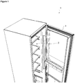
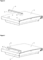
- the cooling device (1) comprises at least one cabinet (2) wherein the foodstuffs to be cooled are placed, at least one door (3) providing access into the cabinet (2), at least one handle (4) providing the opening/closing of the door (3), at least one housing (5) located on the door (3), at least one support member (6) that is arranged on the surface of the handle (4) facing the door (3) and that aligns with the housing (5) while the handle (4) is being fixed to the door (3) and at least one locking mechanism (7) providing the assembly of the handle (4) to the door (3) ( Figure 1 , Figure 2, Figure 3 ).
- the locking mechanism (7) comprises;
- the support member (6) and the housing (5) are aligned and the retainer (8) extends into the housing (5).
- the retainer (8) moves downwards so that the detent means (10) is seated into the opening (9).
- the detent means (10) contacts the retainer (8) and prevents the retainer (8) from moving.
- the handle (4) is fixed to the door (3).
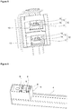
- the locking mechanism (7) comprises a carrier (13) whereon the detent means (10) is seated.
- the retainer (8) is seated onto the carrier (13) after passing over the detent means (10) and the retainer (8) is prevented from moving downwards.
- a strong connection is obtained between the door (3) and the handle (4) ( Figure 4 , Figure 5 ).
- the locking mechanism (7) comprises at least two extensions (11) that extend from two sides of the carrier (13) so as to contact the retainer (8) from its opposite sides.
- the detent means (10) comprises a stopper (12) that is arranged between the extensions (11) and that prevents the movement of the retainer (8) by bearing against the retainer (8) when the extensions (11) are placed into the opening (9). While the detent means (10) passes through the opening (9), the stopper (12) stretches to allow the movement of the retainer (8) in the downward direction and when the retainer (8) entirely grasps the detent means (10) returns to its initial position and applies pressure to the retainer (8). Thus, the retainer (8) is prevented from moving upwards ( Figure 5 ).
- the stopper (12) comprises an upright member (14) extending along the extension (11) and a barrier (15) arranged at the upper end of the upright member (14), bearing against the retainer (8) when the retainer (8) is placed onto the detent means (10).
- the detent means (10) starts entering into the opening (9)
- the retainer (8) contacts the barrier (15) and pushes the stopper (12) backwards.
- the stopper (12) is at a position behind its initial position due to the flexible structure of the upright member (14) and does not prevent the retainer (8) from moving.
- the barrier (15) is released from the retainer (8) and bears against the retainer (8) and prevents the retainer (8) from moving upwards ( Figure 5 , Figure 7 ).
- the free end of the barrier (15) is inclined.
- the retainer (8) more easily pushes the barrier (15) and hence the stopper (12) backwards without preventing their movements, when the retainer (8) touches the barrier (15) for the first time.
- the retainer (8) is formed as a hollow half truncated cone.
- the retainer (8) widens from top to bottom and the distance between the extensions (11) decreases from the carrier (13) towards the ends.
- the locking process is more easily realized since the extensions (11) do not force the retainer (8) until they entirely enter into the retainer (8).
- the locking mechanism (7) comprises a cavity (16) formed on the surface of the support member (6) so as to almost align with the retainer (8).
- the detent means (10) is provided to move more easily between the retainer (8) and the support member (6).
- the locking mechanism (7) is produced from plastic material.
- the movement ability of the locking mechanism (7) is improved and the assembly process is provided to be realized more easily.
- the cooling device (1) comprises one support member (6) on each of the lower and upper ends of the handle (4), two housings (5) positioned so as to align with the support members (6) and two locking mechanisms (7) located at each housing (5) - support member (6) pair.
- the handle (4) is easily mounted onto the door (3) without requiring any tool. Thus, component and labor costs are decreased.
Landscapes
- Engineering & Computer Science (AREA)
- Chemical & Material Sciences (AREA)
- Combustion & Propulsion (AREA)
- Physics & Mathematics (AREA)
- Mechanical Engineering (AREA)
- Thermal Sciences (AREA)
- General Engineering & Computer Science (AREA)
- Refrigerator Housings (AREA)
Priority Applications (1)
| Application Number | Priority Date | Filing Date | Title |
|---|---|---|---|
| PL12729141T PL2723957T3 (pl) | 2011-06-23 | 2012-06-25 | Urządzenie chłodzące zawierające łatwo montowany uchwyt |
Applications Claiming Priority (2)
| Application Number | Priority Date | Filing Date | Title |
|---|---|---|---|
| TR201106212 | 2011-06-23 | ||
| PCT/EP2012/062181 WO2012175732A2 (en) | 2011-06-23 | 2012-06-25 | A cooling device comprising an easily mountable handle |
Publications (2)
| Publication Number | Publication Date |
|---|---|
| EP2723957A2 EP2723957A2 (en) | 2014-04-30 |
| EP2723957B1 true EP2723957B1 (en) | 2019-01-09 |
Family
ID=46331333
Family Applications (1)
| Application Number | Title | Priority Date | Filing Date |
|---|---|---|---|
| EP12729141.7A Active EP2723957B1 (en) | 2011-06-23 | 2012-06-25 | A cooling device comprising an easily mountable handle |
Country Status (5)
| Country | Link |
|---|---|
| EP (1) | EP2723957B1 (pl) |
| CN (1) | CN103608534B (pl) |
| PL (1) | PL2723957T3 (pl) |
| TR (1) | TR201718082T3 (pl) |
| WO (1) | WO2012175732A2 (pl) |
Families Citing this family (5)
| Publication number | Priority date | Publication date | Assignee | Title |
|---|---|---|---|---|
| EP3123087A1 (en) * | 2014-03-28 | 2017-02-01 | Arçelik Anonim Sirketi | Improved handle assembly for refrigeration appliance door |
| CN109577743B (zh) * | 2017-09-29 | 2021-04-20 | 合肥华凌股份有限公司 | 冰箱把手和冰箱 |
| WO2020224851A1 (en) * | 2019-05-07 | 2020-11-12 | Arcelik Anonim Sirketi | A refrigerator comprising a door handle |
| US20230148387A1 (en) * | 2021-11-08 | 2023-05-11 | Haier Us Appliance Solutions, Inc. | Slide and lock appliance handle mounting |
| CN217737645U (zh) * | 2022-05-13 | 2022-11-04 | 宁波韩电电器有限公司 | 一种冰箱门的把手机构 |
Citations (1)
| Publication number | Priority date | Publication date | Assignee | Title |
|---|---|---|---|---|
| US3426385A (en) * | 1967-04-10 | 1969-02-11 | Illinois Tool Works | Socket-type fastener |
Family Cites Families (14)
| Publication number | Priority date | Publication date | Assignee | Title |
|---|---|---|---|---|
| US2621357A (en) * | 1949-11-25 | 1952-12-16 | Roper Corp Geo D | Handle mounting means |
| KR100347031B1 (ko) | 1999-12-28 | 2002-08-03 | 엘지전자주식회사 | 냉장고의 도어핸들 장착구조 |
| US6871385B2 (en) * | 2002-07-16 | 2005-03-29 | Maytag Corporation | Refrigerator handle mounting arrangement |
| JP2004143793A (ja) | 2002-10-24 | 2004-05-20 | Ykk Ap Inc | 把手 |
| US7549713B2 (en) * | 2002-11-18 | 2009-06-23 | Maytag Corporation | Refrigerator handle mounting arrangement |
| KR20070065743A (ko) | 2005-12-20 | 2007-06-25 | 주식회사 대우일렉트로닉스 | 냉장고의 도어핸들 고정구조 |
| KR100719254B1 (ko) | 2006-07-21 | 2007-05-18 | 주식회사 대우일렉트로닉스 | 냉장고 도어 핸들 고정장치 |
| CN101033908A (zh) * | 2007-04-27 | 2007-09-12 | 海尔集团公司 | 冰箱门把手 |
| CN201047190Y (zh) * | 2007-05-25 | 2008-04-16 | 伊莱克斯(中国)电器有限公司 | 一种冰箱把手 |
| KR20090014048A (ko) * | 2007-08-03 | 2009-02-06 | 엘지전자 주식회사 | 전자제품의 트림킷 도어 어셈블리 |
| KR100876689B1 (ko) * | 2007-08-27 | 2008-12-31 | 엘지전자 주식회사 | 냉장고 및 냉장고 도어 |
| AU2008216999B2 (en) * | 2007-10-25 | 2014-11-13 | Aktiebolaget Electrolux | A Handle Assembly |
| US8215731B2 (en) * | 2008-07-09 | 2012-07-10 | Whirlpool Corporation | Handle assembly for a domestic appliance |
| BRPI0902214A2 (pt) * | 2009-06-10 | 2011-03-01 | Electrolux Do Brasil Sa | sistemas de encaixe para puxadores |
-
2012
- 2012-06-25 EP EP12729141.7A patent/EP2723957B1/en active Active
- 2012-06-25 TR TR2017/18082T patent/TR201718082T3/tr unknown
- 2012-06-25 CN CN201280030832.7A patent/CN103608534B/zh not_active Expired - Fee Related
- 2012-06-25 WO PCT/EP2012/062181 patent/WO2012175732A2/en not_active Ceased
- 2012-06-25 PL PL12729141T patent/PL2723957T3/pl unknown
Patent Citations (1)
| Publication number | Priority date | Publication date | Assignee | Title |
|---|---|---|---|---|
| US3426385A (en) * | 1967-04-10 | 1969-02-11 | Illinois Tool Works | Socket-type fastener |
Also Published As
| Publication number | Publication date |
|---|---|
| EP2723957A2 (en) | 2014-04-30 |
| CN103608534A (zh) | 2014-02-26 |
| WO2012175732A2 (en) | 2012-12-27 |
| CN103608534B (zh) | 2015-12-23 |
| WO2012175732A3 (en) | 2013-08-08 |
| TR201718082T3 (tr) | 2017-12-21 |
| PL2723957T3 (pl) | 2019-08-30 |
Similar Documents
| Publication | Publication Date | Title |
|---|---|---|
| EP2723957B1 (en) | A cooling device comprising an easily mountable handle | |
| JP6466522B2 (ja) | ブラケット装置及びブラケット装置を含むスライドレールアセンブリ | |
| CN112444077B (zh) | 可实现重心内移的冰箱 | |
| US8632141B2 (en) | Sliding apparatus with self-closing means | |
| AU2016419709B2 (en) | Mechanism for opening door from the left or the right, and refrigerator | |
| JP5048027B2 (ja) | 傘の下ろくろ係脱装置 | |
| CN112443221B (zh) | 带有可活动铰链组件的冰箱 | |
| CN112444068B (zh) | 嵌入式对开门冰箱 | |
| CN112444064A (zh) | 嵌入式冰箱 | |
| CN112444062B (zh) | 可增加开度的冰箱 | |
| EP3656251B1 (en) | Slide rail assembly | |
| CN112444086B (zh) | 带有多轴铰链组件的嵌入式冰箱 | |
| WO2013041679A2 (en) | A cooling device comprising a shelf the height of which can be adjusted | |
| EP3403530B1 (en) | Driving mechanism, protection device and control method applicable to furniture | |
| KR100888167B1 (ko) | 도어 개폐유닛 | |
| WO2013050399A2 (en) | A shelf suitable for use on the cooling device door | |
| KR200451771Y1 (ko) | 미닫이도어의 이동안내부재 고정구조 | |
| CN112444078B (zh) | 可实现重心内移的冰箱 | |
| KR200447878Y1 (ko) | 폴딩도어의 이동안내장치 | |
| CN112444079B (zh) | 可增加开度的冰箱 | |
| CN220256271U (zh) | 盖体组件及具有其的烹饪器具 | |
| CN112444069A (zh) | 带有多轴铰链组件的冰箱 | |
| WO2009083406A2 (en) | A cooling device | |
| KR20140074521A (ko) | 냉장고 | |
| KR200437504Y1 (ko) | 레일 조립체 |
Legal Events
| Date | Code | Title | Description |
|---|---|---|---|
| PUAI | Public reference made under article 153(3) epc to a published international application that has entered the european phase |
Free format text: ORIGINAL CODE: 0009012 |
|
| 17P | Request for examination filed |
Effective date: 20131119 |
|
| AK | Designated contracting states |
Kind code of ref document: A2 Designated state(s): AL AT BE BG CH CY CZ DE DK EE ES FI FR GB GR HR HU IE IS IT LI LT LU LV MC MK MT NL NO PL PT RO RS SE SI SK SM TR |
|
| DAX | Request for extension of the european patent (deleted) | ||
| STAA | Information on the status of an ep patent application or granted ep patent |
Free format text: STATUS: EXAMINATION IS IN PROGRESS |
|
| 17Q | First examination report despatched |
Effective date: 20170803 |
|
| GRAP | Despatch of communication of intention to grant a patent |
Free format text: ORIGINAL CODE: EPIDOSNIGR1 |
|
| STAA | Information on the status of an ep patent application or granted ep patent |
Free format text: STATUS: GRANT OF PATENT IS INTENDED |
|
| INTG | Intention to grant announced |
Effective date: 20180913 |
|
| GRAS | Grant fee paid |
Free format text: ORIGINAL CODE: EPIDOSNIGR3 |
|
| GRAA | (expected) grant |
Free format text: ORIGINAL CODE: 0009210 |
|
| STAA | Information on the status of an ep patent application or granted ep patent |
Free format text: STATUS: THE PATENT HAS BEEN GRANTED |
|
| AK | Designated contracting states |
Kind code of ref document: B1 Designated state(s): AL AT BE BG CH CY CZ DE DK EE ES FI FR GB GR HR HU IE IS IT LI LT LU LV MC MK MT NL NO PL PT RO RS SE SI SK SM TR |
|
| REG | Reference to a national code |
Ref country code: GB Ref legal event code: FG4D |
|
| REG | Reference to a national code |
Ref country code: CH Ref legal event code: EP Ref country code: AT Ref legal event code: REF Ref document number: 1087483 Country of ref document: AT Kind code of ref document: T Effective date: 20190115 |
|
| REG | Reference to a national code |
Ref country code: IE Ref legal event code: FG4D |
|
| REG | Reference to a national code |
Ref country code: DE Ref legal event code: R096 Ref document number: 602012055688 Country of ref document: DE |
|
| REG | Reference to a national code |
Ref country code: NL Ref legal event code: MP Effective date: 20190109 |
|
| REG | Reference to a national code |
Ref country code: LT Ref legal event code: MG4D |
|
| PG25 | Lapsed in a contracting state [announced via postgrant information from national office to epo] |
Ref country code: NL Free format text: LAPSE BECAUSE OF FAILURE TO SUBMIT A TRANSLATION OF THE DESCRIPTION OR TO PAY THE FEE WITHIN THE PRESCRIBED TIME-LIMIT Effective date: 20190109 |
|
| RAP2 | Party data changed (patent owner data changed or rights of a patent transferred) |
Owner name: ARCELIK ANONIM SIRKETI |
|
| REG | Reference to a national code |
Ref country code: AT Ref legal event code: MK05 Ref document number: 1087483 Country of ref document: AT Kind code of ref document: T Effective date: 20190109 |
|
| PG25 | Lapsed in a contracting state [announced via postgrant information from national office to epo] |
Ref country code: FI Free format text: LAPSE BECAUSE OF FAILURE TO SUBMIT A TRANSLATION OF THE DESCRIPTION OR TO PAY THE FEE WITHIN THE PRESCRIBED TIME-LIMIT Effective date: 20190109 Ref country code: NO Free format text: LAPSE BECAUSE OF FAILURE TO SUBMIT A TRANSLATION OF THE DESCRIPTION OR TO PAY THE FEE WITHIN THE PRESCRIBED TIME-LIMIT Effective date: 20190409 Ref country code: SE Free format text: LAPSE BECAUSE OF FAILURE TO SUBMIT A TRANSLATION OF THE DESCRIPTION OR TO PAY THE FEE WITHIN THE PRESCRIBED TIME-LIMIT Effective date: 20190109 Ref country code: ES Free format text: LAPSE BECAUSE OF FAILURE TO SUBMIT A TRANSLATION OF THE DESCRIPTION OR TO PAY THE FEE WITHIN THE PRESCRIBED TIME-LIMIT Effective date: 20190109 Ref country code: PT Free format text: LAPSE BECAUSE OF FAILURE TO SUBMIT A TRANSLATION OF THE DESCRIPTION OR TO PAY THE FEE WITHIN THE PRESCRIBED TIME-LIMIT Effective date: 20190509 Ref country code: LT Free format text: LAPSE BECAUSE OF FAILURE TO SUBMIT A TRANSLATION OF THE DESCRIPTION OR TO PAY THE FEE WITHIN THE PRESCRIBED TIME-LIMIT Effective date: 20190109 |
|
| PG25 | Lapsed in a contracting state [announced via postgrant information from national office to epo] |
Ref country code: LV Free format text: LAPSE BECAUSE OF FAILURE TO SUBMIT A TRANSLATION OF THE DESCRIPTION OR TO PAY THE FEE WITHIN THE PRESCRIBED TIME-LIMIT Effective date: 20190109 Ref country code: HR Free format text: LAPSE BECAUSE OF FAILURE TO SUBMIT A TRANSLATION OF THE DESCRIPTION OR TO PAY THE FEE WITHIN THE PRESCRIBED TIME-LIMIT Effective date: 20190109 Ref country code: BG Free format text: LAPSE BECAUSE OF FAILURE TO SUBMIT A TRANSLATION OF THE DESCRIPTION OR TO PAY THE FEE WITHIN THE PRESCRIBED TIME-LIMIT Effective date: 20190409 Ref country code: IS Free format text: LAPSE BECAUSE OF FAILURE TO SUBMIT A TRANSLATION OF THE DESCRIPTION OR TO PAY THE FEE WITHIN THE PRESCRIBED TIME-LIMIT Effective date: 20190509 Ref country code: GR Free format text: LAPSE BECAUSE OF FAILURE TO SUBMIT A TRANSLATION OF THE DESCRIPTION OR TO PAY THE FEE WITHIN THE PRESCRIBED TIME-LIMIT Effective date: 20190410 Ref country code: RS Free format text: LAPSE BECAUSE OF FAILURE TO SUBMIT A TRANSLATION OF THE DESCRIPTION OR TO PAY THE FEE WITHIN THE PRESCRIBED TIME-LIMIT Effective date: 20190109 |
|
| REG | Reference to a national code |
Ref country code: DE Ref legal event code: R097 Ref document number: 602012055688 Country of ref document: DE |
|
| PG25 | Lapsed in a contracting state [announced via postgrant information from national office to epo] |
Ref country code: DK Free format text: LAPSE BECAUSE OF FAILURE TO SUBMIT A TRANSLATION OF THE DESCRIPTION OR TO PAY THE FEE WITHIN THE PRESCRIBED TIME-LIMIT Effective date: 20190109 Ref country code: EE Free format text: LAPSE BECAUSE OF FAILURE TO SUBMIT A TRANSLATION OF THE DESCRIPTION OR TO PAY THE FEE WITHIN THE PRESCRIBED TIME-LIMIT Effective date: 20190109 Ref country code: AT Free format text: LAPSE BECAUSE OF FAILURE TO SUBMIT A TRANSLATION OF THE DESCRIPTION OR TO PAY THE FEE WITHIN THE PRESCRIBED TIME-LIMIT Effective date: 20190109 Ref country code: CZ Free format text: LAPSE BECAUSE OF FAILURE TO SUBMIT A TRANSLATION OF THE DESCRIPTION OR TO PAY THE FEE WITHIN THE PRESCRIBED TIME-LIMIT Effective date: 20190109 Ref country code: RO Free format text: LAPSE BECAUSE OF FAILURE TO SUBMIT A TRANSLATION OF THE DESCRIPTION OR TO PAY THE FEE WITHIN THE PRESCRIBED TIME-LIMIT Effective date: 20190109 Ref country code: AL Free format text: LAPSE BECAUSE OF FAILURE TO SUBMIT A TRANSLATION OF THE DESCRIPTION OR TO PAY THE FEE WITHIN THE PRESCRIBED TIME-LIMIT Effective date: 20190109 Ref country code: SK Free format text: LAPSE BECAUSE OF FAILURE TO SUBMIT A TRANSLATION OF THE DESCRIPTION OR TO PAY THE FEE WITHIN THE PRESCRIBED TIME-LIMIT Effective date: 20190109 |
|
| PLBE | No opposition filed within time limit |
Free format text: ORIGINAL CODE: 0009261 |
|
| STAA | Information on the status of an ep patent application or granted ep patent |
Free format text: STATUS: NO OPPOSITION FILED WITHIN TIME LIMIT |
|
| PG25 | Lapsed in a contracting state [announced via postgrant information from national office to epo] |
Ref country code: SM Free format text: LAPSE BECAUSE OF FAILURE TO SUBMIT A TRANSLATION OF THE DESCRIPTION OR TO PAY THE FEE WITHIN THE PRESCRIBED TIME-LIMIT Effective date: 20190109 |
|
| 26N | No opposition filed |
Effective date: 20191010 |
|
| PG25 | Lapsed in a contracting state [announced via postgrant information from national office to epo] |
Ref country code: MC Free format text: LAPSE BECAUSE OF FAILURE TO SUBMIT A TRANSLATION OF THE DESCRIPTION OR TO PAY THE FEE WITHIN THE PRESCRIBED TIME-LIMIT Effective date: 20190109 |
|
| REG | Reference to a national code |
Ref country code: CH Ref legal event code: PL |
|
| PG25 | Lapsed in a contracting state [announced via postgrant information from national office to epo] |
Ref country code: SI Free format text: LAPSE BECAUSE OF FAILURE TO SUBMIT A TRANSLATION OF THE DESCRIPTION OR TO PAY THE FEE WITHIN THE PRESCRIBED TIME-LIMIT Effective date: 20190109 |
|
| REG | Reference to a national code |
Ref country code: BE Ref legal event code: MM Effective date: 20190630 |
|
| PG25 | Lapsed in a contracting state [announced via postgrant information from national office to epo] |
Ref country code: IE Free format text: LAPSE BECAUSE OF NON-PAYMENT OF DUE FEES Effective date: 20190625 |
|
| PG25 | Lapsed in a contracting state [announced via postgrant information from national office to epo] |
Ref country code: CH Free format text: LAPSE BECAUSE OF NON-PAYMENT OF DUE FEES Effective date: 20190630 Ref country code: LI Free format text: LAPSE BECAUSE OF NON-PAYMENT OF DUE FEES Effective date: 20190630 Ref country code: BE Free format text: LAPSE BECAUSE OF NON-PAYMENT OF DUE FEES Effective date: 20190630 Ref country code: LU Free format text: LAPSE BECAUSE OF NON-PAYMENT OF DUE FEES Effective date: 20190625 |
|
| PG25 | Lapsed in a contracting state [announced via postgrant information from national office to epo] |
Ref country code: CY Free format text: LAPSE BECAUSE OF FAILURE TO SUBMIT A TRANSLATION OF THE DESCRIPTION OR TO PAY THE FEE WITHIN THE PRESCRIBED TIME-LIMIT Effective date: 20190109 |
|
| PG25 | Lapsed in a contracting state [announced via postgrant information from national office to epo] |
Ref country code: MT Free format text: LAPSE BECAUSE OF FAILURE TO SUBMIT A TRANSLATION OF THE DESCRIPTION OR TO PAY THE FEE WITHIN THE PRESCRIBED TIME-LIMIT Effective date: 20190109 Ref country code: HU Free format text: LAPSE BECAUSE OF FAILURE TO SUBMIT A TRANSLATION OF THE DESCRIPTION OR TO PAY THE FEE WITHIN THE PRESCRIBED TIME-LIMIT; INVALID AB INITIO Effective date: 20120625 |
|
| PG25 | Lapsed in a contracting state [announced via postgrant information from national office to epo] |
Ref country code: MK Free format text: LAPSE BECAUSE OF FAILURE TO SUBMIT A TRANSLATION OF THE DESCRIPTION OR TO PAY THE FEE WITHIN THE PRESCRIBED TIME-LIMIT Effective date: 20190109 |
|
| PGFP | Annual fee paid to national office [announced via postgrant information from national office to epo] |
Ref country code: DE Payment date: 20250618 Year of fee payment: 14 Ref country code: PL Payment date: 20250613 Year of fee payment: 14 |
|
| PGFP | Annual fee paid to national office [announced via postgrant information from national office to epo] |
Ref country code: GB Payment date: 20250618 Year of fee payment: 14 |
|
| PGFP | Annual fee paid to national office [announced via postgrant information from national office to epo] |
Ref country code: FR Payment date: 20250624 Year of fee payment: 14 |
|
| PGFP | Annual fee paid to national office [announced via postgrant information from national office to epo] |
Ref country code: TR Payment date: 20250616 Year of fee payment: 14 |
|
| PGFP | Annual fee paid to national office [announced via postgrant information from national office to epo] |
Ref country code: IT Payment date: 20250624 Year of fee payment: 14 |