EP2723553B1 - Automated ply layup system and method of laying up - Google Patents
Automated ply layup system and method of laying up Download PDFInfo
- Publication number
- EP2723553B1 EP2723553B1 EP12724465.5A EP12724465A EP2723553B1 EP 2723553 B1 EP2723553 B1 EP 2723553B1 EP 12724465 A EP12724465 A EP 12724465A EP 2723553 B1 EP2723553 B1 EP 2723553B1
- Authority
- EP
- European Patent Office
- Prior art keywords
- ply
- end effector
- plies
- camera
- robot
- Prior art date
- Legal status (The legal status is an assumption and is not a legal conclusion. Google has not performed a legal analysis and makes no representation as to the accuracy of the status listed.)
- Active
Links
- 238000000034 method Methods 0.000 title claims description 55
- 239000012636 effector Substances 0.000 claims description 157
- 239000000758 substrate Substances 0.000 claims description 35
- 239000002131 composite material Substances 0.000 claims description 14
- 238000005056 compaction Methods 0.000 claims description 13
- 239000000853 adhesive Substances 0.000 claims description 11
- 230000001070 adhesive effect Effects 0.000 claims description 11
- 230000001939 inductive effect Effects 0.000 claims 1
- 238000004519 manufacturing process Methods 0.000 description 15
- 239000000463 material Substances 0.000 description 14
- 230000008569 process Effects 0.000 description 13
- 239000000945 filler Substances 0.000 description 12
- 239000002184 metal Substances 0.000 description 11
- 229910052751 metal Inorganic materials 0.000 description 11
- 238000009787 hand lay-up Methods 0.000 description 7
- 238000010586 diagram Methods 0.000 description 6
- 239000011888 foil Substances 0.000 description 6
- -1 prepregs Substances 0.000 description 4
- RYGMFSIKBFXOCR-UHFFFAOYSA-N Copper Chemical compound [Cu] RYGMFSIKBFXOCR-UHFFFAOYSA-N 0.000 description 3
- 239000012790 adhesive layer Substances 0.000 description 3
- 230000005686 electrostatic field Effects 0.000 description 3
- 238000012423 maintenance Methods 0.000 description 3
- 238000009727 automated fiber placement Methods 0.000 description 2
- 230000008901 benefit Effects 0.000 description 2
- 239000011248 coating agent Substances 0.000 description 2
- 238000000576 coating method Methods 0.000 description 2
- 238000007689 inspection Methods 0.000 description 2
- 150000002739 metals Chemical class 0.000 description 2
- 238000012544 monitoring process Methods 0.000 description 2
- 239000012811 non-conductive material Substances 0.000 description 2
- 229920000642 polymer Polymers 0.000 description 2
- 238000002360 preparation method Methods 0.000 description 2
- 238000001454 recorded image Methods 0.000 description 2
- 229920001169 thermoplastic Polymers 0.000 description 2
- 239000004416 thermosoftening plastic Substances 0.000 description 2
- 210000000707 wrist Anatomy 0.000 description 2
- 241001137251 Corvidae Species 0.000 description 1
- 238000009786 automated tape laying Methods 0.000 description 1
- 239000000919 ceramic Substances 0.000 description 1
- 238000009734 composite fabrication Methods 0.000 description 1
- 239000004020 conductor Substances 0.000 description 1
- 229910052802 copper Inorganic materials 0.000 description 1
- 239000010949 copper Substances 0.000 description 1
- 238000013461 design Methods 0.000 description 1
- 239000000428 dust Substances 0.000 description 1
- 230000000694 effects Effects 0.000 description 1
- 230000007613 environmental effect Effects 0.000 description 1
- 239000000835 fiber Substances 0.000 description 1
- 238000003384 imaging method Methods 0.000 description 1
- 230000010354 integration Effects 0.000 description 1
- 239000010410 layer Substances 0.000 description 1
- 230000004048 modification Effects 0.000 description 1
- 238000012986 modification Methods 0.000 description 1
- 229910052755 nonmetal Inorganic materials 0.000 description 1
- 230000003287 optical effect Effects 0.000 description 1
- 230000008520 organization Effects 0.000 description 1
- 235000015108 pies Nutrition 0.000 description 1
- 239000004033 plastic Substances 0.000 description 1
- 229920003023 plastic Polymers 0.000 description 1
- 239000011253 protective coating Substances 0.000 description 1
- 238000009419 refurbishment Methods 0.000 description 1
- 230000002441 reversible effect Effects 0.000 description 1
- 230000037303 wrinkles Effects 0.000 description 1
Images


Classifications
-
- B—PERFORMING OPERATIONS; TRANSPORTING
- B29—WORKING OF PLASTICS; WORKING OF SUBSTANCES IN A PLASTIC STATE IN GENERAL
- B29C—SHAPING OR JOINING OF PLASTICS; SHAPING OF MATERIAL IN A PLASTIC STATE, NOT OTHERWISE PROVIDED FOR; AFTER-TREATMENT OF THE SHAPED PRODUCTS, e.g. REPAIRING
- B29C70/00—Shaping composites, i.e. plastics material comprising reinforcements, fillers or preformed parts, e.g. inserts
- B29C70/04—Shaping composites, i.e. plastics material comprising reinforcements, fillers or preformed parts, e.g. inserts comprising reinforcements only, e.g. self-reinforcing plastics
- B29C70/28—Shaping operations therefor
- B29C70/30—Shaping by lay-up, i.e. applying fibres, tape or broadsheet on a mould, former or core; Shaping by spray-up, i.e. spraying of fibres on a mould, former or core
- B29C70/38—Automated lay-up, e.g. using robots, laying filaments according to predetermined patterns
-
- B—PERFORMING OPERATIONS; TRANSPORTING
- B25—HAND TOOLS; PORTABLE POWER-DRIVEN TOOLS; MANIPULATORS
- B25J—MANIPULATORS; CHAMBERS PROVIDED WITH MANIPULATION DEVICES
- B25J13/00—Controls for manipulators
- B25J13/08—Controls for manipulators by means of sensing devices, e.g. viewing or touching devices
- B25J13/085—Force or torque sensors
-
- B—PERFORMING OPERATIONS; TRANSPORTING
- B25—HAND TOOLS; PORTABLE POWER-DRIVEN TOOLS; MANIPULATORS
- B25J—MANIPULATORS; CHAMBERS PROVIDED WITH MANIPULATION DEVICES
- B25J15/00—Gripping heads and other end effectors
-
- B—PERFORMING OPERATIONS; TRANSPORTING
- B25—HAND TOOLS; PORTABLE POWER-DRIVEN TOOLS; MANIPULATORS
- B25J—MANIPULATORS; CHAMBERS PROVIDED WITH MANIPULATION DEVICES
- B25J15/00—Gripping heads and other end effectors
- B25J15/0085—Gripping heads and other end effectors with means for applying an electrostatic force on the object to be gripped
-
- B—PERFORMING OPERATIONS; TRANSPORTING
- B25—HAND TOOLS; PORTABLE POWER-DRIVEN TOOLS; MANIPULATORS
- B25J—MANIPULATORS; CHAMBERS PROVIDED WITH MANIPULATION DEVICES
- B25J15/00—Gripping heads and other end effectors
- B25J15/06—Gripping heads and other end effectors with vacuum or magnetic holding means
- B25J15/0616—Gripping heads and other end effectors with vacuum or magnetic holding means with vacuum
-
- B—PERFORMING OPERATIONS; TRANSPORTING
- B25—HAND TOOLS; PORTABLE POWER-DRIVEN TOOLS; MANIPULATORS
- B25J—MANIPULATORS; CHAMBERS PROVIDED WITH MANIPULATION DEVICES
- B25J19/00—Accessories fitted to manipulators, e.g. for monitoring, for viewing; Safety devices combined with or specially adapted for use in connection with manipulators
- B25J19/02—Sensing devices
- B25J19/021—Optical sensing devices
- B25J19/022—Optical sensing devices using lasers
-
- B—PERFORMING OPERATIONS; TRANSPORTING
- B25—HAND TOOLS; PORTABLE POWER-DRIVEN TOOLS; MANIPULATORS
- B25J—MANIPULATORS; CHAMBERS PROVIDED WITH MANIPULATION DEVICES
- B25J19/00—Accessories fitted to manipulators, e.g. for monitoring, for viewing; Safety devices combined with or specially adapted for use in connection with manipulators
- B25J19/02—Sensing devices
- B25J19/021—Optical sensing devices
- B25J19/023—Optical sensing devices including video camera means
-
- B—PERFORMING OPERATIONS; TRANSPORTING
- B25—HAND TOOLS; PORTABLE POWER-DRIVEN TOOLS; MANIPULATORS
- B25J—MANIPULATORS; CHAMBERS PROVIDED WITH MANIPULATION DEVICES
- B25J9/00—Programme-controlled manipulators
- B25J9/16—Programme controls
-
- B—PERFORMING OPERATIONS; TRANSPORTING
- B25—HAND TOOLS; PORTABLE POWER-DRIVEN TOOLS; MANIPULATORS
- B25J—MANIPULATORS; CHAMBERS PROVIDED WITH MANIPULATION DEVICES
- B25J9/00—Programme-controlled manipulators
- B25J9/16—Programme controls
- B25J9/1694—Programme controls characterised by use of sensors other than normal servo-feedback from position, speed or acceleration sensors, perception control, multi-sensor controlled systems, sensor fusion
- B25J9/1697—Vision controlled systems
-
- Y—GENERAL TAGGING OF NEW TECHNOLOGICAL DEVELOPMENTS; GENERAL TAGGING OF CROSS-SECTIONAL TECHNOLOGIES SPANNING OVER SEVERAL SECTIONS OF THE IPC; TECHNICAL SUBJECTS COVERED BY FORMER USPC CROSS-REFERENCE ART COLLECTIONS [XRACs] AND DIGESTS
- Y10—TECHNICAL SUBJECTS COVERED BY FORMER USPC
- Y10T—TECHNICAL SUBJECTS COVERED BY FORMER US CLASSIFICATION
- Y10T156/00—Adhesive bonding and miscellaneous chemical manufacture
- Y10T156/10—Methods of surface bonding and/or assembly therefor
Definitions
- the present disclosure generally relates to the fabrication of laminated structures, especially those formed of composites, and deals more particularly with a system for automated layup of plies on a tool.
- a group of plies arranged as a kit may be sequentially laid up at particular locations on a tool in order to strengthen, stiffen or otherwise provide a structure with desired structural or performance characteristics.
- the use of a ply kit may be efficient in some applications since it frees automated tape laying equipment from laying up many relatively small plies in localized areas.
- Ply kits may be used, for example and without limitation, where it is desirable to fill gaps between stringers and frames of an airframe using a composite filler.
- the filler comprises a set of laminated filler plies that are sequentially placed on a tool before full plies are laid up over the filler.
- the filler plies may be placed within pockets in the tool that are specially shaped and located to form a shaped filler when the pocket is filled with plies. In the past, the layup process was performed by hand.
- Hand layup techniques may be required in other applications. For example, it may be necessary to layup plies, such as doublers in precise locations on a substrate relative to each other. Using hand layup techniques, the technician must place each individual ply on the substrate at a precise location relative to other plies. Moreover, the hand layup technique requires placement of plies one-at-a-time, and the size of the plies is limited to that which the technician can manually handle. In other applications, hand layup may be necessary where the ply material is relatively delicate and/or subject to wrinkling, creasing or tearing when processed by AFP machines. For example, protection of aircraft against lightning strikes may be achieved by applying a grid of thin copper foil-sheets to exterior skins of the aircraft. The grids are assembled by one-at-a-time by hand layup of hundreds of pieces of relatively small thin copper foil sheets that may be subject to wrinkling, denting, creasing and/or tearing during the layup process.
- a handling apparatus for material pieces wherein the handling apparatus has one or more handling devices, which are a multi-axis manipulator with a handling tool for receiving and dispersing at least one piece of material, where the handling tool has at least one rotatable material carrier, that is formed as a reel or a material carrier for receiving a plurality of pieces of material.
- the handling apparatus has one or more handling devices, which are a multi-axis manipulator with a handling tool for receiving and dispersing at least one piece of material, where the handling tool has at least one rotatable material carrier, that is formed as a reel or a material carrier for receiving a plurality of pieces of material.
- EP 1857260 in accordance with its abstract, states systems and methods for monitoring automated composite fabrication processes are disclosed.
- a method includes performing a manufacturing operation on a portion of a workpiece using a tool moveable relative to the workpiece. Simultaneously with performing the manufacturing operation, the tool is translated relative to the workpiece, and a portion of the workpiece upon which the tool has performed the manufacturing operation is monitored.
- the monitoring includes illuminating an illuminated strip of the workpiece using a laser, and receiving a reflected beam reflected from the illuminated strip into a camera. Output signals from the camera may be analyzed to detect and characterize a feature of interest, wherein the feature of interest may include an edge, an overlap, a gap, a wrinkle, and foreign object debris.
- a system for laying composite plies at preselected locations comprising a robot; an end effector on the robot for lifting a ply from a ply kit and placing the ply at a preselected location, the end effector comprising a scanner; a camera; a gripper; and a force sensor; a stationary camera for recording the position of the ply on the end effector; and a controller coupled with the robot and the end effector, wherein the scanner is on the end effector for detecting features relating to the location where the ply is to be placed; wherein the camera functions to record images of the plies in the ply kit which are processed by image recognition software forming part of the controller to recognise and select individual plies in a layup sequence; wherein the gripper is configured to releasably grip one or more plies on the end effector until ready for placement at the preselected location; wherein the controller receives inputs from the scanner, camera, force sensor and stationary camera and functions to control the operation of
- a method of laying up plies at predetermined locations on a substrate comprising picking up a ply by gripping the ply with an end effector, the end effector comprising a scanner, a camera, a gripper and a force sensor; moving the ply to an area adjacent a predetermined location where the ply is to be placed by moving the end effector to the area adjacent the predetermined location; recording the position of the ply on the end effector using a stationary camera; orienting the ply relative to the predetermined location where the ply is to be placed; placing the oriented ply at the predetermined location on the substrate using the end effector, wherein the method further comprises using the scanner on the end effector to detect features related to the location where the ply is to be placed, wherein using the end effector to place the ply is based on the detected features, and moving the end effector to the area adjacent the predetermined location is performed using an automatically controlled robotic manipulator, the robotic manipulator and end effector
- the disclosed embodiments provide an automated layup system that is well suited for laying up groups of plies, such as kitted fillers, doublers as well as other types of plies for a variety of applications.
- the process of selecting a desired ply in sequence from a ply kit, transferring the selected ply to a tool and placing the ply at the correct location on the tool is performed automatically by a robotically controlled end effector.
- the end effector optically recognizes the correct ply to be lifted from the kit and detects features on the tool that are used to locate the ply during ply placement and compaction.
- the system may reduce or eliminate ply wrinkling and may provide more precise control of the layup process.
- a variety of plies may be picked up and placed by the end effector such as, without limitation thermoplastics, prepregs, metal foils and adhesive layers, to name a few.
- the end effector may be employed to pre-inspect a localized area of a tool before the plies are placed on the tool or to post inspect the placed ply to ensure proper alignment.
- a system for laying composite plies at preselected locations.
- An end effector on a robot lifts a ply and places the ply at a preselected location.
- a stationary camera is provided for recording the position of the ply on the end effector, and a controller is coupled with the robot and the end effector to place the ply.
- the end effector may include a vacuum operated gripper for gripping the ply when it is lifted in preparation for placement.
- the stationary camera may be configured to viewing the ply.
- the system further comprise a camera on the end effector coupled with the controller for viewing the ply before it is lifted by the end effector, and the controller may include software for recognizing and selecting the ply from a plurality of plies.
- the system also includes a detector on the end effector for detecting the location of features at the placement location that are used to adjust the placement of the ply.
- the detector may comprise a 3-D laser scanner.
- the end effector on the robot is used to apply a compaction force to the ply as it is being placed, and the system further comprises a force sensor on the end effector for sensing the amount of the compaction force.
- a system for automatically laying up plies on a substrate.
- the system comprises an end effector for placing each of the plies on the substrate, and a robot for manipulating the end effector.
- a detector is provided on the end effector for detecting features on the tool.
- a controller coupled with the detector on the robot controls the end effector to place the ply on the substrate at a location based on the detected features on the substrate.
- the detector may be a laser scanner adapted for scanning the surface of the substrate.
- the system may further comprise a camera on the end effector for recording an image of the ply before the ply is lifted, and a controller may include object recognition software for recognizing the image recorded by the camera.
- the system may further comprise a camera for recording an image of the ply on the end effector, wherein the controller is operative for determining the position of the ply on the end effector after being lifted.
- a method of laying up plies at predetermined locations on a substrate.
- the method comprises picking up a ply, moving the ply to an area adjacent a predetermined location on a substrate, orienting the ply relative to the predetermined location where the ply is to be placed, and placing the ply at the predetermined location on the substrate.
- An end effector is used to pickup the ply, and move it to an area adjacent the substrate.
- the end effector is used to detect features on the substrate representing a predetermined location where the ply is to be placed.
- the end effector is also used to place the ply on the substrate based on detected features.
- Picking up the ply may include gripping the ply on the end effector by holding the ply against the end effector with a vacuum. Moving the end effector to the area adjacent the tool is performed using an automatically controlled robotic manipulator.
- Using the end effector to detect features on the substrate includes using a non-contact scanner to scan the surface of the substrate.
- the method may further comprise using the end effector to compact the ply against the substrate, and using a sensor on the end effector to sense the compaction force applied by the end effector to the ply.
- a method is provided of fabricating a composite aircraft structure.
- the method comprises providing a plurality of composite plies and using a robotically controlled end effector to pickup one of the plies.
- the method also includes determining the position of the ply on the end effector and using the end effector to move the ply to the area of the tool.
- the end effector is used to place the ply on the tool based on the position of the ply on the end effector.
- the end effector may also be used to identify the ply to be picked up.
- a method of reducing the time required to fabricate a multi-ply composite structure comprises using an automatically controlled tape layup machine to layup courses of composite tape forming plies on a tool, and using a robotically controlled end effector to place plies on local areas of the tool.
- the method may include using an electroadhesive gripper to grip the ply, and placing the gripped ply on the substrate.
- Using the electroadhesive gripper to grip the ply includes adhering the ply to the gripper by generating an electrostatic adhesive force between the gripper and the ply.
- a method of laying up plies of conductive metal foil on an aircraft skin.
- the method comprises using an end effector to pick up the plies, including using an electrostatic adhesive force to grip the plies, and moving the end effector to an area on the skin.
- the method further comprises using the end effector to place the plies on the skin.
- Placing the plies on the skin includes releasing the electrostatic adhesive force gripping the plies on the end effector.
- Gripping the plies includes generating electrostatic fields on the gripper, and using the electrostatic fields to induce electrostatic charges on the ply.
- a system for laying up plies on a substrate, comprising an end effector including an electrostatic gripper for releasably gripping the plies using an electrostatic adhesive force, and a robotic manipulator for manipulating the end effector.
- the system further comprises a programmed controller for automatically controlling the operation of the robotic manipulator and the electrostatic gripper.
- the electrostatic gripper includes a plurality of alternating positive and negative electrode pads adapted to be coupled with a source of electrical power.
- the gripper includes a backing plate, and the electrode pads are located on the backing plate. A polymeric coating protectively covering the electrode pads.
- the system further comprises a device for recording the position of the ply on the end effector, and a detector on the end effector for detecting features on the substrate where the plies are to be laid up.
- the disclosed embodiments relate to an automated ply layup system generally indicated by the numeral 18 that automatically places 25 plies 48 on a substrate 21 such as a tool 28 or a previously placed ply (not shown) on the tool 28.
- the plies 48 form part of a ply kit 24 comprising a preselected number of plies 48 having the same or different fiber orientations that are intended to be laid up on the tool 28 in a predetermined sequence to form a feature such as a doubler (not shown) or a filler (not shown) on a composite structure (not shown).
- the plies 48 are placed 25 at specific locations on the tool 28 during the layup process.
- the plies 48 are sequentially placed 25 in one or more pockets 26 in the tool. While layup of composite plies 48 is described in the illustrated examples, the disclosed embodiments may be employed to layup or place other objects, and especially those in the form of flexible or non-flexible sheet-like or flat materials, including without limitation, plastics, ceramics and metals and composites in various forms, which may be electrically conductive or non-conductive. Accordingly, the term "ply" as used herein is intended to include a wide variety of shapes and materials.
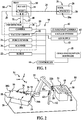
- the automated ply placement system 18 broadly comprises an end effector 20 mounted on a robot 22 or similar automatically controlled manipulator, a stationary camera 42 and a controller 44.
- the end effector 20 comprises a scanner 36, a camera 30, a vacuum gripper 32 and a force sensor 34.
- the camera 30 functions to record images of the plies 40 in the kit 24 which are processed by image recognition software 45 forming part of the controller 44 to recognize and select 27 individual plies 48 in the proper layup sequence.
- the vacuum gripper 32 may be coupled with a vacuum system 40 and functions to releasably grip 29 individual plies 48 in order to hold 29 the ply 48 on the end effector 20 until ready for placement 25 on the tool 28.
- the vacuum gripper 32 may also be connected to a pressurized air supply 43.
- the air supply 43 may be used to apply positive pressure to the ply 48 which may aid in releasing the ply 48 after its placement.
- the end effector 20 may be equipped with other types of ply grippers, as will be discussed
- the scanner 36 may comprise, for example and without limitation, a 2-D or 3-D laser scanner which scans the surface of the tool 28 to identify the location of features such as pockets 26.
- the force sensor 34 on the end effector 20 functions to sense the amount of compaction force being applied to the ply 48. This sensed compaction force is fed back to a controller 44 which may respond by adjusting the compaction force applied by the robot 22.
- the stationary camera 42 functions to record an image of a ply 48 gripped by the end effector which is used by the controller 44 to determine the position, i.e. placement and/or orientation, of the ply 48 on the end effector 20.
- the end effector 20 and the robot 22 are coupled with the controller 44 which receives inputs from the scanner 36, camera 30, force sensor 34 and the stationary camera 42 and functions to control the operation of the end effector 20 and robot 22.
- the robot 22 moves the end effector 20 to a work cell 50 where the tray 30 is located so that the plies 48 in the ply kit 24 are within the field-of-view of the camera 30.
- the controller 44 recognizes and selects 27 the next ply 48 to be laid up on the tool 28.
- the camera 30 may record images within the work cell 50 that reflect other information such as the size and/or shape of one or more of the plies 48.
- the end effector 20 may include other sensing equipment, such as, without limitation, an RFID (radio frequency identification) reader (not shown) that senses information useful in connection with selection and/or placement of plies 48 that may be stored in an RFID tag (not shown) or other device.
- RFID radio frequency identification
- the end effector 20 uses the vacuum gripper 32 to lift and hold 29 the selected ply 48 on the end effector 20 while the robot 22 moves the selected ply to a location that is within the field-of-view of the stationary camera 42.
- the stationary camera 42 functions as a device for recording the position (placement and/or orientation) of the ply 48 on the end effector 20 by recording an image of the ply 48 gripped by the end effector 20.
- the recorded image of the ply 48 is delivered to the controller 44 which uses the recorded image to determine the position of the ply 48 on the end effector 20.
- the controller 44 then translates the recorded position of the ply 48 into the 3-D spatial coordinate system 54 ( FIG. 2 ) used by the robot 22, by applying offsets to the recorded position of the ply 48 or using other techniques.
- the robot 22 moves the end effector 20 from the stationary camera 42 to a location in the area of the tool 28, typically facing the tool 28.
- the scanner 36 on the end effector 20 is then used to scan the tool 28 to identify features such as pocket 26 that may be used to determine the location where the selected ply is to be placed on the tool 28.
- the scanner 36 may be used to locate the edges 26a (see FIG. 4 ) of the pocket 26.
- the location of the edges 26a is used by the controller 44 to control the robot 22 which moves the end effector 20 until the selected ply 48 is positioned to place the ply 48 at the desired location on the tool 28, which in the illustrated example, corresponds to a pocket 26.
- the end effector 20 then places 25 the selected ply 48 on the tool 28 within the pocket 26, aligned with edges 26a or with other features of the pocket 26.
- the end effector 20 then compacts 31 the ply 48 against the tool 28 with a desired amount of force which is measured by the force sensor 34 on the end effector 20.
- the scanner 36 on the end effector 20 may also be used to pre-inspect localized areas of the tool 28 prior to ply placement, as well as to perform a post inspection of the plies 48 and/or the tool 28 after the plies 48 have been placed to verify that laid up features such as doublers and fillers are correctly located on the tool 28 and/or in relation to other layup features.
- Pre-inspection of the tool 28 may be desirable where variations may occur in the location of certain tool features. For example, and without limitation, variations may occur in the exact location of the pockets 26, from tool-to-tool, due to original tool manufacturing tolerances and/or due to rework or maintenance of the tool during its life-cycle.
- use of the scanner 36 on the end effector 20 allows the actual (measured) location of the pockets 26 on a particular tool 28 to be determined, in contrast to relying on the nominal (as-designed) location of the pockets 26 as the basis for ply placement location.
- the amount of force applied by the robot 22 to compact 31 the ply 48 is controlled by the controller 44, using the force measured by the force sensor 34 as a feedback signal.
- the vacuum gripper 32 releases the ply 48 and the end effector 20 moves away from the tool 28, back to the work cell 50 in order to pickup the next-in-sequence ply 48 in the kit 24.
- the air supply 43 may be used to effect positive release of the ply 48 from the gripper 32 before the end effector moves away from the tool 28.
- FIG. 2 illustrates one typical implementation of the automated ply layup system 18 shown in FIG. 1 .
- the numeral 54 designates the 3-D spatial coordinate system used by the robot 22 to lift, transport and place the plies 48 at the desired locations on the tool 28.
- the robot 22 may comprise any suitable automated manipulator, including but not limited to conveyors and transporters, but in the illustrated embodiment is depicted as being an articulated type having an articulating arm 22a which may assist in orienting a ply 48 with a location on the tool 28 during the placement process.
- the arm 22a is provided with a rotatable wrist 22b to which the end effector 20 is mounted.
- the robot 22 has a reach extending from the work cell 50 to the tool 28 from which the plies 48 are to be laid up.
- the ply kit 24 comprises an array of plies 48 placed on a removable tray 30, with the plies 48 facing upwardly and within reach of the robot 22.
- the stationary camera 42 is mounted on a support 52, between the work cell 50 and the tool 28, however other locations of the camera 42 are possible. Placement of the camera 42 between the work cell 50 and the tool 28 allows the robot 22 to move the ply 48 into the field-of-view of the camera 42 as the robot 22 pivots and the end effector 20 swings in an arc from the work cell 50 to the tool 28.
- the camera 42 may comprise any suitable imaging device capable of producing a digital image of the ply 48 lifted by the end effector 20. In some embodiments, the use of more than one camera 42 may be desirable.
- the tool 28 is depicted as a curved mandrel having a plurality of aligned pockets 26 in the tool surface 28a.
- One or more optical reflectors 55 may be placed on the surface 28a of the tool 28 to aid in the approximate positioning of the end effector 20 over the tool 28 prior to the ply 48 being placed.
- the reflectors 55 may be detected by the laser scanner 36 ( FIG. 1 ), however the laser scanner 36 may sense other features of the tool 28 for the purpose of approximately positioning the end effector 20, such as detecting the edges 28b of the tool 28.
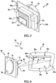
- FIG. 3 illustrates additional details of the end effector 20.
- the laser scanner 36, vacuum gripper 32 and camera 30 are mounted on one face 58a of a mounting plate 58.
- the vacuum gripper 32 may include a perforated face 32a that is coupled with the vacuum system 40 ( FIG. 1 ) and is adapted to hold a ply 48 thereon.
- the perforated face 32a may also be coupled with the air supply 43 shown in FIG. 1 to allow positive air pressure to be applied to the ply 48 when it is being released from the gripper 32.
- the force sensor 34 is mounted on the opposite face 58b of the plate 58 and may comprise, for example and without limitation, a pizoelectric device.
- An adapter 56 secured to the plate 58 adapts the end effector 20 to be coupled with the wrist 22b of the robot 22.
- FIG. 4 illustrates the end effector 20 having been approximately positioned above one of the pockets 26 in the tool 28, in preparation for placing a ply 48 in the pocket 26.
- the pocket 26 may include inclined side walls 26a.
- the laser scanner 36 is used to scan the pocket 26a to determine its location on the tool 28 and with in the 3-D spatial coordinate system 54.
- the laser scanner 36 may be of the 3-D scanning type which generates a three dimensional model of the pocket 26 that includes the inclined sidewalls 26b as well as the edges 26a of the pocket 26.
- the controller 44 FIG. 1
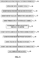
- FIG. 5 illustrates the overall steps of an automated method of laying up plies 48, such as filler plies.
- an operator places a tray 30 with a kit 24 of plies 48 at a work cell 50.
- the operator initiates a robot cycle using the controller 44.
- the robot 22 moves the end effector 20 to a position overlying the tray 30 at the work cell 50.
- the camera 30 on the end effector 20 selects 27 a particular ply 48 in the kit 24 that is next-in-sequence to be laid up.
- the robot 22 moves the vacuum gripper 48 into contact with the selected ply 48, thereby gripping 29 the ply 48 and lifting it as the robot 20 moves the end effector 20 away from the work cell 50 and toward the stationary camera 42.
- the robot 22 presents the selected 27 ply 48 to the stationary camera 42 which records an image showing the position of the ply 48 relative to the end effector 22.
- the stationary camera 42 in cooperation with the controller 44, locates the ply 48 within the 3-D coordinate reference system 54 of the robot 22.
- the robot 22 moves the selected ply 48 to a position over the tooling 28, and at 80, the laser scanner 36 measures the approximate location of the pockets 26 by detecting the reflectors 35 or detecting other features such as the edges 28b of the tooling 28.
- the robot 22 moves the laser scanner 36 into proximity with a pocket 26 and the scanner 36 then scans the pocket 26, as previously discussed in connection with FIG. 4 .
- the robot 22 With the precise location of the pocket 26 known within the 3-D coordinate reference system 54, the robot 22 then places 25 the ply 48 precisely in the pocket 26, as shown in step 82, either on the tool 28 or on a ply 48 that has been previously placed in the pocket 26.
- the force sensor 34 is used to develop a feedback signal during the compaction process which is used by a controller 40 to determine the amount of force to be applied to the ply 48 by the robot as it is being compacted 29 on the tool 28.
- Positive air pressure may be applied to the ply 48 by the air supply 42 (FOG. 1) in order to assure that the ply 48 is released from the gripper 32.
- steps 64 to 84 are repeated for each of the plies 48 in sequence until the filler has been completed.
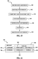
- FIG. 6 illustrates the overall steps of a method for automated layup of ply doublers.
- a composite tape layup machine or an automated fiber placement machine places the initial plies on a mandrel such as the tool 28 shown in FIG. 2 .
- a kit of doubler plies 48 is placed in the work cell 50.
- an operator initiates a robot cycle, and at 94, the robot 22 moves the end effector 20 over the kit 30.
- the camera 30 locates and selects 27 the next-in-sequence doubler ply 48 in the kit 30.
- the robot 22 then moves the vacuum gripper 32 on the end effector 20 into contact with the doubler ply 48 and at 100, the robot 22 lifts the selected doubler ply 48 from the kit 30 using the vacuum gripper 32.
- the robot 22 presents the doubler ply 48 to the stationary camera 42 and at 104, the stationary camera 42 locates the doubler ply 48 precisely on the face 32a of the vacuum gripper 32.
- the robot 22 moves the end effector 20 to a position over the mandrel tool 28, and the laser scanner 36 may be used to detect features that are used to determine the exact location where the doubler ply 48 is to be placed.
- the detected features may comprise, without limitation, reflectors 55 on the tool 28, the edges 28b of the tool 28, or the edges (not shown) of a previously placed ply 48.
- the robot 22 places 25 the doubler ply 48 on the tool surface 28a or on an already placed doubler ply 48.
- the robot 22 uses the force sensor 34 to provide feedback to the controller 44 indicating the amount of compaction force that is being applied to the doubler ply 48 during the compaction process 29.
- steps 92-110 are repeated until all of the doubler plies 48 have been placed on the mandrel tool 28.
- the composite tape layup machine or the automated fiber placement machine continues the layup process of full plies over the doubler plies 48, and at 106, the placement of doubler plies 48 is repeated, as needed or as dictated by a predetermined ply schedule.
- FIG. 7 broadly illustrates apparatus 107 that may be used in an automated ply layup system, such as the system 54 shown in FIG. 2 .
- the apparatus 107 may be used to pick up and transport plies 48, and place 23 them on a substrate 21, such as a tool 28 ( FIG. 2 ), a previously laid ply 48, or other substrates (not shown).
- the apparatus 107 comprises an end effector 20 manipulated by a robot 22 which may be similar to that previously described in connection with FIGS. 1-3 .
- the end effector 20 includes an electroadhesive gripper 108 that uses reversible electrostatic adhesion to grip one or more plies 48 on the end effector 20 while being transported and placed on the tool 28.
- the electroadhesive gripper 108 is powered by an electrical power supply 110 and generates an electrostatic adhesive force "F" that is used to releasably adhere the ply(s) 48 to the end effector 20.
- FIG. 8 broadly illustrates the steps of a method of laying up plies 38 using the apparatus 107 shown in FIG. 7 .
- the end effector 20 is brought into contact with one or more plies 48, such as those shown in FIG. 1 forming part of a ply kit 24 on a tray 30.
- the plies 48 are picked up and gripped by the gripper 108 using an electrostatic adhesive force "F" which adheres the plies to the gripper 108.
- the end effector 20 and robot 22 move the gripped ply 48 to a substrate 21 such as the tool 28 shown in FIG. 2 .
- the end effector 20 is used to place 23 the ply 48 at a desired location on the substrate 21.
- the end effector 20 may place ply 48 in one of the pockets 26 of the tool 28 shown in FIG. 2 .
- the ply 48 is released from the end effector 20 after being placed 23 in step 118, by removing the electrostatic adhesive force "F" which adheres the ply to the gripper 108.
- the electrostatic adhesive force "F” is removed by turning off electrical power supplied to the gripper 108.
- the apparatus 107 shown in FIG. 7 and the method illustrated in FIG. 8 may be used in an automated layup system 50 shown in FIG. 1 , wherein cameras 30, 42 are used to recognize, sequentially select and pickup plies 48 for layup well as to determine the orientation of plies on an end effector 20 prior to being placed.
- the apparatus 107 shown in FIG. 7 and the method illustrated in FIG. 8 may be employed in other automated layup systems in which an end effector 20 manipulated by a robot 22 is used to automatically place plies 48 on a substrate 21.
- FIGS. 9 and 10 illustrate additional details of one embodiment of the apparatus shown in FIG. 7 .
- the electroadhesive gripper 108 comprises a plurality of alternating positive and negative elongate electrode pads 122, 124 respectively.
- the electrode pads 122, 124 may comprise spaced apart, substantially parallel strips of electrically conductive material, such as without limitation, copper or other suitable metals.
- the electrode pads 122, 124 extend across and are supported on a backing plate 126 mounted on an extension 128 on the end effector 20.
- the positive and negative electrode pads 122, 124 respectively are respectively coupled to the electrical power supply 110 ( FIG. 7 ) which may be a DC power supply that maybe located on-board or off-board the end effector 20.
- the backing plate 126 and the electrode pads 122, 124 are substantially flat, however they may have other geometries, including simple or complex contours, depending on the shape of the plies 48 and/or the tool 28 or other substrate 21 on which the plies 48 are to be placed.
- the electrode pads 122, 124 are substantially rectangular in cross section, however other electrode cross sectional geometries are possible.
- the electrode pads 122, 124 are embedded in a clamp 115 comprising a layer of a suitable non-conductive material such as a polymer attached to the backing plate 126.
- the clamp 115 may comprise a substantially rigid material, or may be a somewhat deformable material that allows the surface 135 of the clamp 115 to generally conform to surface irregularities (not shown) of the gripped ply 48.
- the alternating positive and negative electrode pads 122, 124 When electrical power is supplied to the electroadhesive gripper 108, the alternating positive and negative electrode pads 122, 124 generate electrostatic fields 120 that induce electrostatic + and - charges on the surface 137 of the ply 48.
- the polarities of the + and - charges on the ply 48 are opposite to those of the electrode pads 122, 124, resulting in generation of an electrostatic adhesion force "F" that attracts and thereby adheres the ply 48 to the surface 135 of the gripper 108.
- the electroadhesive gripper 108 may generate relatively large electrostatic adhesive forces "F” using relatively small amounts of power. For example, and without limitation, power requirements may be on the order of approximately 20 microwatts/Newton weight.
- the electrostatic adhesive force "F” may be modulated, and turned on and off by controlling the power supplied to the electrode pads 122, 124. On-off switching times may be on the order of less than approximately 50 milliseconds
- the electroadhesive gripper 108 may be used to grip conductive or non-conductive pies 48 formed of any of various materials that have rough or smooth surfaces and/or which may have dust and/or debris on the surface thereof.
- the electroadhesive gripper 108 may be used to grip ply materials such as thermoplastics, prepregs, metal foils, metal and non-metal meshes and adhesive layers, to name only a few.
- FIG. 12 illustrates an alternate form of the gripper 108 in which the electrode pads 122, 124 are pads adhered directly to a non-conductive backing plate 126.
- a polymeric or other type of coating 132 protectively covers the electrode pads 122, 124.
- the electrode pads 122, 124 may be individually encapsulated in or surrounded by a protective coating of nonconductive material such as a polymer.
- the disclosed end effector 20 having an electroadhesive gripper 108 may be used to pick up, grip, transport and place a single ply 48, or as illustrated in FIG. 13 , multiple plies 48a, 48b, 48c may be simultaneously picked up, gripped and placed by the end effector 20.
- the multiple plies 48a, 48b, 48c may be prearranged in precise relationships to each other on a tray 40 ( FIG. 1 ) forming part of the station 50 or on other surfaces.
- the plies 48a, 48b, 48c When simultaneously gripped and picked up by the electroadhesive gripper, the plies 48a, 48b, 48c remain in their prearranged relationship while they are placed and compacted on a tool 28 or other substrate 21 by the end effector 20 as a prearranged group, in contrast to a one-at-a-time automated or hand layup placement process.
- FIG. 14 illustrates the use of the electroadhesive gripper 108 to pick up and grip multiple strips 134 of thin metal foil which may be placed individually or as a group on a substrate 21 such as an aircraft wing (not shown) by the end effector 20.
- the previously described vacuum gripper 32 FIG. 1
- the electrostatic gripper 108 may be used on an end effector 20 to pick up and grip the metal foils strips 134.
- lighting strike protection is implemented by applying sheets of metal mesh (not shown) to an aircraft skin (not shown)
- Embodiments of the disclosure may find use in a variety of potential applications, particularly in the transportation industry, including for example, aerospace, marine, automotive applications and other application where automated layup equipment may be used.
- embodiments of the disclosure may be used in the context of an aircraft manufacturing and service method 136 as shown in Figure 15 and an aircraft 138 as shown in Figure 16 .
- Aircraft applications of the disclosed embodiments may include, for example, without limitation, layup of stiffened members such as fuselage skins, wing skins, control surfaces, hatches, floor panels, door panels, access panels and empennages, layup of adhesive layers and layup of thin sheets of metal foil for lightning strike applications, to name a few.
- exemplary method 108 may include specification and design 140 of the aircraft 138 and material procurement 142. During production, component and subassembly manufacturing 144 and system integration 146 of the aircraft 138 takes place. Thereafter, the aircraft 138 may go through certification and delivery 148 in order to be placed in service 150. While in service by a customer, the aircraft 138 is scheduled for routine maintenance and service 152 (which may also include modification, reconfiguration, refurbishment, and so on.
- a system integrator may include without limitation any number of aircraft manufacturers and major-system subcontractors; a third party may include without limitation any number of vendors, subcontractors, and suppliers; and an operator may be an airline, leasing company, military entity, service organization, and so on.
- the aircraft 138 produced by exemplary method 136 may include an airframe 154 with a plurality of systems 156 and an interior 158.
- high-level systems 156 include one or more of a propulsion system 160, an electrical system 162, a hydraulic system 164, and an environmental system 166. Any number of other systems may be included.
- an aerospace example is shown, the principles of the disclosure may be applied to other industries, such as the marine and automotive industries.
- Systems and methods embodied herein may be employed during any one or more of the stages of the production and service method 136.
- components or subassemblies corresponding to production process 144 may be fabricated or manufactured in a manner similar to components or subassemblies produced while the aircraft 110 is in service.
- one or more apparatus embodiments, method embodiments, or a combination thereof may be utilized during the production stages 144 and 146, for example, by substantially expediting assembly of or reducing the cost of an aircraft 138.
- apparatus embodiments, method embodiments, or a combination thereof may be utilized while the aircraft 138 is in service, for example and without limitation, to maintenance and service 152.
Landscapes
- Engineering & Computer Science (AREA)
- Robotics (AREA)
- Mechanical Engineering (AREA)
- Chemical & Material Sciences (AREA)
- Composite Materials (AREA)
- Human Computer Interaction (AREA)
- Multimedia (AREA)
- Physics & Mathematics (AREA)
- Optics & Photonics (AREA)
- Moulding By Coating Moulds (AREA)
- Manipulator (AREA)
- Processing And Handling Of Plastics And Other Materials For Molding In General (AREA)
Applications Claiming Priority (2)
| Application Number | Priority Date | Filing Date | Title |
|---|---|---|---|
| US13/166,306 US9969131B2 (en) | 2011-06-22 | 2011-06-22 | Automated ply layup system |
| PCT/US2012/038139 WO2012177340A1 (en) | 2011-06-22 | 2012-05-16 | Automated ply layup system and method of laying up |
Publications (2)
| Publication Number | Publication Date |
|---|---|
| EP2723553A1 EP2723553A1 (en) | 2014-04-30 |
| EP2723553B1 true EP2723553B1 (en) | 2020-02-19 |
Family
ID=46178807
Family Applications (1)
| Application Number | Title | Priority Date | Filing Date |
|---|---|---|---|
| EP12724465.5A Active EP2723553B1 (en) | 2011-06-22 | 2012-05-16 | Automated ply layup system and method of laying up |
Country Status (9)
Families Citing this family (80)
| Publication number | Priority date | Publication date | Assignee | Title |
|---|---|---|---|---|
| US8826957B2 (en) | 2012-08-31 | 2014-09-09 | General Electric Company | Methods and systems for automated ply layup for composites |
| DE102012019841B4 (de) * | 2012-10-09 | 2022-01-05 | Grenzebach Maschinenbau Gmbh | Verfahren und Vorrichtung für das Umsetzen großflächiger Platten in extremer Übergröße |
| DE102012019839B4 (de) * | 2012-10-09 | 2017-08-24 | Grenzebach Maschinenbau Gmbh | Verfahren und Vorrichtung für das Befördern großflächiger Platten in extremer Übergröße |
| US9162436B2 (en) * | 2013-01-04 | 2015-10-20 | The Boeing Company | Method and apparatus for accurate registration of composite laminates |
| CN105579221B (zh) * | 2013-03-12 | 2018-06-08 | 迪芬巴赫机械工程有限公司 | 用于制造先进复合部件的方法和系统 |
| DE102013104609B4 (de) * | 2013-05-06 | 2016-10-20 | Deutsches Zentrum für Luft- und Raumfahrt e.V. | Nestingablage |
| CN103659796A (zh) * | 2013-06-21 | 2014-03-26 | 成都万先自动化科技有限责任公司 | 智能搬运码放定位机器人 |
| KR20150018696A (ko) | 2013-08-08 | 2015-02-24 | 주식회사 케이티 | 감시 카메라 임대 방법, 중계 장치 및 사용자 단말 |
| KR20150018037A (ko) * | 2013-08-08 | 2015-02-23 | 주식회사 케이티 | 관제 시스템 및 이를 이용한 관제 방법 |
| AT514721B1 (de) * | 2013-08-30 | 2015-06-15 | Engel Austria Gmbh | Formgebungsanlage zum Herstellen eines Faser-Kunststoff-Verbundes |
| WO2015095826A1 (en) * | 2013-12-20 | 2015-06-25 | Grabit, Inc. | Modular electroadhesive gripping system |
| WO2015094375A1 (en) * | 2013-12-20 | 2015-06-25 | Grabit, Inc. | Modular electroadhesive gripping system |
| KR20150075224A (ko) | 2013-12-24 | 2015-07-03 | 주식회사 케이티 | 관제 서비스 제공 시스템 및 방법 |
| CA2879277C (en) | 2014-01-22 | 2021-05-04 | Axium Inc. | Vision-assisted robotized depalletizer |
| WO2015142911A1 (en) * | 2014-03-17 | 2015-09-24 | Grabit, Inc. | Electroadhesive gripping system with smart brake and metering |
| WO2015164264A1 (en) | 2014-04-21 | 2015-10-29 | Grabit, Inc. | Automated item handling with reconfigurable totes |
| EP3146397A1 (en) * | 2014-05-20 | 2017-03-29 | Par Systems, Inc. | Adaptive manufacturing system |
| JP6372195B2 (ja) * | 2014-06-30 | 2018-08-15 | 東レ株式会社 | プリフォームの製造方法及び繊維強化プラスチックの製造方法 |
| US9873230B1 (en) | 2014-08-19 | 2018-01-23 | The Boeing Company | Mobile system for automated layup and compaction of composite laminates |
| US10408603B2 (en) | 2014-09-24 | 2019-09-10 | Bombardier Inc. | Laser vision inspection system and method |
| CN104570955B (zh) * | 2014-11-24 | 2018-06-22 | 中国科学院自动化研究所 | 一种复合材料自动铺丝机控制系统及控制方法 |
| DE102015201551A1 (de) * | 2015-01-29 | 2016-08-04 | Bayerische Motoren Werke Aktiengesellschaft | Erkennungsvorrichtung für die Erkennung einer Ausrichtung von Halbzeugzuschnitten |
| US10076883B2 (en) * | 2015-05-05 | 2018-09-18 | The Boeing Company | System and method for manufacturing off-axis prepreg material |
| US10668673B2 (en) | 2015-05-18 | 2020-06-02 | Flightware, Inc. | Systems and methods for automated composite layup quality assurance |
| US9618459B2 (en) | 2015-05-18 | 2017-04-11 | Flightware, Inc. | Systems and methods for automated composite layup quality assurance |
| US10016947B2 (en) * | 2015-05-21 | 2018-07-10 | The Boeing Company | High rate production fiber placement system and method |
| DE102015009177A1 (de) * | 2015-07-09 | 2017-01-12 | Broetje-Automation Gmbh | Verfahren zum Herstellen eines Faser-Metall-Laminatbauteils eines Flugzeugs |
| CN105032836A (zh) * | 2015-08-23 | 2015-11-11 | 华东交通大学 | 机械手式自动插片装置 |
| CN105234943B (zh) * | 2015-09-09 | 2018-08-14 | 大族激光科技产业集团股份有限公司 | 一种基于视觉识别的工业机器人示教装置及方法 |
| JP6762212B2 (ja) * | 2015-12-28 | 2020-09-30 | 帝人株式会社 | 成形体の製造方法 |
| US10155367B2 (en) * | 2015-12-29 | 2018-12-18 | The Boeing Company | Coordinated composite tape laying |
| EP3402636B8 (en) | 2016-01-12 | 2023-01-04 | Grabit, LLC | Methods and systems for combined negative pressure and electroadhesion-based manipulation in manufacturing |
| DE102016003816B4 (de) * | 2016-03-26 | 2019-05-29 | Audi Ag | Industrieroboter mit einem am Manipulator mitgeführten Überwachungsraum |
| JP6665040B2 (ja) * | 2016-06-20 | 2020-03-13 | 三菱重工業株式会社 | ロボット制御システム及びロボット制御方法 |
| GB2552981B (en) * | 2016-08-17 | 2020-04-01 | Univ Of Hertfordshire Higher Education Corporation | An Interactive Humanoid Robot using RFID Tagged Objects |
| US10781056B2 (en) | 2016-12-22 | 2020-09-22 | General Electric Company | Adaptive apparatus and system for automated handling of components |
| US10773902B2 (en) | 2016-12-22 | 2020-09-15 | General Electric Company | Adaptive apparatus and system for automated handling of components |
| US10562244B2 (en) * | 2017-01-23 | 2020-02-18 | The Boeing Company | Systems and methods for forming a composite part based on volume |
| JP2018122381A (ja) * | 2017-01-31 | 2018-08-09 | ブラザー工業株式会社 | 部品保持装置 |
| TWI624044B (zh) * | 2017-03-15 | 2018-05-11 | 啟端光電股份有限公司 | 微元件轉移系統 |
| US20180264660A1 (en) * | 2017-03-20 | 2018-09-20 | Kindred Systems Inc. | Systems, devices, articles, and methods for prehension |
| DE102017110998A1 (de) * | 2017-05-19 | 2018-11-22 | Homag Plattenaufteiltechnik Gmbh | Handhabungseinrichtung zum Handhaben von zumindest abschnittsweise ebenen Gütern, Verfahren zum Betreiben einer derartigen Handhabungseinrichtung |
| US10160169B1 (en) | 2017-06-26 | 2018-12-25 | General Electric Company | Systems and methods of forming a composite layup structure |
| US10195747B1 (en) | 2017-08-03 | 2019-02-05 | General Electric Company | Multi-faced apparatus and system for automated handling of components |
| US10391723B2 (en) * | 2017-08-31 | 2019-08-27 | The Boeing Company | Rotary compaction tool |
| GB2567684B (en) * | 2017-10-20 | 2022-03-30 | Mclaren Automotive Ltd | Composite manufacturing |
| EP3477806B1 (de) * | 2017-10-30 | 2022-03-02 | Komax Holding Ag | Verfahren zum verbinden eines ersten kabels mit einem zweiten kabel, kabelanordnung und kabelverbindungsvorrichtung zum verbinden eines ersten kabels mit einem zweiten kabel |
| CN108081312A (zh) * | 2017-11-03 | 2018-05-29 | 上海工程技术大学 | 一种用于抓取小型零件的机器人机械手对中校准系统 |
| AT520587B1 (de) * | 2017-11-14 | 2021-03-15 | Engel Austria Gmbh | Verfahren zum Anordnen von Halbzeugen |
| US10843449B2 (en) | 2017-12-14 | 2020-11-24 | The Boeing Company | Method and apparatus for forming composite plies on contoured tool surfaces |
| US10899089B2 (en) | 2018-03-30 | 2021-01-26 | The Boeing Company | Automated fiber placement end effector with laminar gas cooling jet and infrared image processor for in-situ inspection |
| US10926490B2 (en) * | 2018-04-09 | 2021-02-23 | The Boeing Company | Composite laminate forming apparatus and method therefor |
| US10695916B2 (en) * | 2018-07-05 | 2020-06-30 | The Boeing Company | End effectors having reconfigurable vacuum heads |
| US11007635B2 (en) | 2018-07-25 | 2021-05-18 | The Boeing Company | Gravity compensation for self-propelled robotic vehicles crawling on non-level surfaces |
| WO2020033484A1 (en) * | 2018-08-07 | 2020-02-13 | University Of Southern California | Hybrid formation of multi-layer prepreg composite sheet layup |
| CN113329865B (zh) | 2018-10-15 | 2023-12-29 | 通用电气公司 | 自动化膜移除的系统和方法 |
| US11305498B2 (en) * | 2018-12-21 | 2022-04-19 | The Boeing Company | System and method for fabricating a composite ply layup |
| US11318689B2 (en) * | 2018-12-21 | 2022-05-03 | The Boeing Company | Ply transporting and compacting apparatus and method therefor |
| JP7161399B2 (ja) * | 2018-12-28 | 2022-10-26 | 株式会社Subaru | 樹脂含浸測定装置 |
| US11141814B2 (en) | 2019-03-04 | 2021-10-12 | The Boeing Company | Thermographic inspection for tape layup machines |
| US11040500B2 (en) | 2019-03-04 | 2021-06-22 | The Boeing Company | Thermographic inspection for tape layup machines |
| US11192665B2 (en) | 2019-03-04 | 2021-12-07 | The Boeing Company | Thermographic inspection of lanes of tape laid-up by tape layup machines, based on acquired thermographic images |
| US11198260B2 (en) | 2019-03-04 | 2021-12-14 | The Boeing Company | Thermographic inspection for tape layup machines |
| CN110065288A (zh) * | 2019-04-02 | 2019-07-30 | 深圳市联得自动化装备股份有限公司 | 贴合设备及贴合方法 |
| GB201907911D0 (en) * | 2019-06-04 | 2019-07-17 | Blade Dynamics Ltd | Wind turbine blade tool and method for producing a wind turbine blade |
| GB201908127D0 (en) * | 2019-06-07 | 2019-07-24 | Renishaw Plc | Manufacturing method and apparatus |
| NL2023372B1 (en) | 2019-06-25 | 2021-02-01 | Airborne Int B V | Preforming system and method |
| NL2023504B1 (en) * | 2019-07-15 | 2021-02-08 | Airborne Int B V | Apparatus and method for processing consolidated stacks of fiber reinforced plies |
| FR3101569B1 (fr) * | 2019-10-08 | 2021-09-10 | Safran Nacelles | Machine de drapage et de compactage automatique |
| EP3875227A1 (en) * | 2020-03-06 | 2021-09-08 | Scape Technologies A/S | Method of operating a picking robot and related devices |
| US11351678B1 (en) * | 2020-03-10 | 2022-06-07 | Amazon Technologies, Inc. | Dynamically adjustable suction cups |
| US11472139B2 (en) | 2020-05-15 | 2022-10-18 | The Boeing Company | Automated composite fabrication systems and methods |
| KR102426189B1 (ko) * | 2020-12-22 | 2022-07-28 | 주식회사 대덕알앤디 | 스마트 eoat 로봇 시스템 |
| CN113899333A (zh) * | 2021-09-29 | 2022-01-07 | 苏州佳祺仕信息科技有限公司 | 一种距离测量方法、装置、电子设备及存储介质 |
| US12066819B2 (en) | 2021-10-13 | 2024-08-20 | The Boeing Company | Printed fiducial system for accurate pick and place |
| US11951697B2 (en) * | 2021-12-12 | 2024-04-09 | The Boeing Company | Scalable area gripper, system, and method for a material handling process for composite manufacturing |
| KR102786582B1 (ko) * | 2022-08-30 | 2025-03-24 | 한국로봇융합연구원 | 협동 로봇 공정 셀을 기반으로 하는 자동으로 프리프레그를 적층하기 위한 장치 및 이를 위한 방법 |
| US12327344B2 (en) * | 2022-08-31 | 2025-06-10 | The Boeing Company | Natural feature pick and place system for composite materials |
| US20250026122A1 (en) * | 2023-07-17 | 2025-01-23 | The Boeing Company | Composite Lamination System and Methods |
| US20250128509A1 (en) * | 2023-10-19 | 2025-04-24 | The Boeing Company | Composite Backing Layer Peel Starter |
Citations (6)
| Publication number | Priority date | Publication date | Assignee | Title |
|---|---|---|---|---|
| EP1857260A1 (en) * | 2006-05-16 | 2007-11-21 | The Boeing Company | Systems and methods for monitoring automated composite fabrication processes |
| US20070271064A1 (en) * | 2006-05-16 | 2007-11-22 | The Boeing Company | System and method for identifying a feature of a workpiece |
| DE202007006528U1 (de) * | 2007-05-04 | 2008-09-18 | Kuka Systems Gmbh | Einrichtung zum Handhaben von Materialstücken |
| DE102007061431A1 (de) * | 2007-12-20 | 2009-06-25 | Airbus Deutschland Gmbh | Verfahren zur Versteifung eines Faserverbundbauteils sowie Vakuummatte und Anordnung zur Herstellung eines versteiften Faserverbundbauteils |
| DE102008032574A1 (de) * | 2008-07-11 | 2010-01-14 | Brötje-Automation GmbH | Vorrichtung zur Verwendung bei der Herstellung faserverstärkter Bauteile |
| DE102010044721A1 (de) * | 2010-09-08 | 2012-03-08 | Daimler Ag | Verfahren und Vorrichtung zum Herstellen eines Faserhalbzeugs |
Family Cites Families (19)
| Publication number | Priority date | Publication date | Assignee | Title |
|---|---|---|---|---|
| JPS62104740A (ja) | 1985-11-01 | 1987-05-15 | Hitachi Ltd | 多層印刷回路板の層構成装置 |
| US5876550A (en) | 1988-10-05 | 1999-03-02 | Helisys, Inc. | Laminated object manufacturing apparatus and method |
| US5183670A (en) | 1991-04-30 | 1993-02-02 | United Technologies Corporation | Bi-functional transfer foot |
| US5209804A (en) | 1991-04-30 | 1993-05-11 | United Technologies Corporation | Integrated, automted composite material manufacturing system for pre-cure processing of preimpregnated composite materials |
| US6131973A (en) | 1998-10-01 | 2000-10-17 | Sikorsky Aircraft Corporation | Vacuum transfer device |
| US7930061B2 (en) * | 2002-08-31 | 2011-04-19 | Applied Materials, Inc. | Methods and apparatus for loading and unloading substrate carriers on moving conveyors using feedback |
| WO2004035897A2 (en) * | 2002-09-12 | 2004-04-29 | David Groppe | Precision feed end-effector composite fabric tape-laying apparatus and method |
| JP4174342B2 (ja) * | 2003-02-19 | 2008-10-29 | ファナック株式会社 | ワーク搬送装置 |
| US7341086B2 (en) * | 2004-10-29 | 2008-03-11 | The Boeing Company | Automated fabric layup system and method |
| US8601694B2 (en) | 2008-06-13 | 2013-12-10 | The Boeing Company | Method for forming and installing stringers |
| US7766063B2 (en) * | 2005-04-28 | 2010-08-03 | The Boeing Company | Machine assisted laminator and method |
| US7551419B2 (en) * | 2006-06-05 | 2009-06-23 | Sri International | Electroadhesion |
| JP2008310724A (ja) * | 2007-06-18 | 2008-12-25 | Nippon Telegr & Teleph Corp <Ntt> | 3次元形状復元装置,3次元形状復元方法,3次元形状復元プログラム及びそのプログラムを格納した記録媒体 |
| US8936695B2 (en) | 2007-07-28 | 2015-01-20 | The Boeing Company | Method for forming and applying composite layups having complex geometries |
| JP2009148858A (ja) | 2007-12-21 | 2009-07-09 | Pioneer Electronic Corp | 電子部品配置装置 |
| US9694546B2 (en) * | 2008-02-12 | 2017-07-04 | The Boeing Company | Automated fiber placement compensation |
| JP4475339B2 (ja) | 2008-02-26 | 2010-06-09 | トヨタ自動車株式会社 | パワーアシスト装置およびその制御方法 |
| US20100063304A1 (en) * | 2008-09-09 | 2010-03-11 | Basf Se | Apparatus for automatic catalyst exchange in a reactor with a bundle of catalyst tubes |
| JP5647148B2 (ja) | 2009-01-11 | 2014-12-24 | アプライド マテリアルズ インコーポレイテッドApplied Materials,Incorporated | 基板を輸送する静電エンドエフェクタ装置、システム、および方法 |
-
2011
- 2011-06-22 US US13/166,306 patent/US9969131B2/en not_active Expired - Fee Related
-
2012
- 2012-05-16 KR KR1020137026689A patent/KR101958032B1/ko not_active Expired - Fee Related
- 2012-05-16 CA CA2832229A patent/CA2832229C/en not_active Expired - Fee Related
- 2012-05-16 JP JP2014516972A patent/JP6095655B2/ja not_active Expired - Fee Related
- 2012-05-16 CN CN201280030394.4A patent/CN103619567A/zh active Pending
- 2012-05-16 EP EP12724465.5A patent/EP2723553B1/en active Active
- 2012-05-16 WO PCT/US2012/038139 patent/WO2012177340A1/en unknown
- 2012-05-16 ES ES12724465T patent/ES2784153T3/es active Active
- 2012-05-16 PT PT127244655T patent/PT2723553T/pt unknown
Patent Citations (6)
| Publication number | Priority date | Publication date | Assignee | Title |
|---|---|---|---|---|
| EP1857260A1 (en) * | 2006-05-16 | 2007-11-21 | The Boeing Company | Systems and methods for monitoring automated composite fabrication processes |
| US20070271064A1 (en) * | 2006-05-16 | 2007-11-22 | The Boeing Company | System and method for identifying a feature of a workpiece |
| DE202007006528U1 (de) * | 2007-05-04 | 2008-09-18 | Kuka Systems Gmbh | Einrichtung zum Handhaben von Materialstücken |
| DE102007061431A1 (de) * | 2007-12-20 | 2009-06-25 | Airbus Deutschland Gmbh | Verfahren zur Versteifung eines Faserverbundbauteils sowie Vakuummatte und Anordnung zur Herstellung eines versteiften Faserverbundbauteils |
| DE102008032574A1 (de) * | 2008-07-11 | 2010-01-14 | Brötje-Automation GmbH | Vorrichtung zur Verwendung bei der Herstellung faserverstärkter Bauteile |
| DE102010044721A1 (de) * | 2010-09-08 | 2012-03-08 | Daimler Ag | Verfahren und Vorrichtung zum Herstellen eines Faserhalbzeugs |
Non-Patent Citations (2)
| Title |
|---|
| HOSODA K ET AL: "Adaptive hybrid visual servoing/force control in unknown environment", INTELLIGENT ROBOTS AND SYSTEMS '96, IROS 96, PROCEEDINGS OF THE 1996 L EEE/RSJ INTERNATIONAL CONFERENCE ON OSAKA, JAPAN 4-8 NOV. 1996, NEW YORK, NY, USA,IEEE, US, vol. 3, 4 November 1996 (1996-11-04), pages 1097 - 1103, XP010212561, ISBN: 978-0-7803-3213-3, DOI: 10.1109/IROS.1996.568956 * |
| NELSON B J ET AL: "Integrating force and vision feedback within virtual environments for telerobotic systems", ROBOTICS AND AUTOMATION, 1997. PROCEEDINGS., 1997 IEEE INTERNATIONAL C ONFERENCE ON ALBUQUERQUE, NM, USA 20-25 APRIL 1997, IEEE, NEW YORK, NY, USA, vol. 2, 20 April 1997 (1997-04-20), pages 1588 - 1593, XP010235542, ISBN: 978-0-7803-3612-4, DOI: 10.1109/ROBOT.1997.614367 * |
Also Published As
| Publication number | Publication date |
|---|---|
| ES2784153T3 (es) | 2020-09-22 |
| PT2723553T (pt) | 2020-03-27 |
| WO2012177340A1 (en) | 2012-12-27 |
| CA2832229A1 (en) | 2012-12-27 |
| US20120330453A1 (en) | 2012-12-27 |
| KR101958032B1 (ko) | 2019-03-13 |
| WO2012177340A9 (en) | 2013-02-14 |
| JP2014522747A (ja) | 2014-09-08 |
| CA2832229C (en) | 2016-11-22 |
| JP6095655B2 (ja) | 2017-03-15 |
| KR20140033351A (ko) | 2014-03-18 |
| EP2723553A1 (en) | 2014-04-30 |
| CN103619567A (zh) | 2014-03-05 |
| US9969131B2 (en) | 2018-05-15 |
Similar Documents
| Publication | Publication Date | Title |
|---|---|---|
| EP2723553B1 (en) | Automated ply layup system and method of laying up | |
| EP3403324B1 (en) | Methods and systems for electroadhesion-based manipulation in manufacturing | |
| US10667581B2 (en) | Automated identification and assembly of shoe parts | |
| US10137544B2 (en) | Method of assembling components | |
| CN109013949A (zh) | 一种可自动粘贴海绵的智能钣金件生产系统 | |
| EP3406430B1 (en) | Pick and place end effector | |
| CN205436162U (zh) | 人工智能钣金件生产系统 | |
| JP7520502B2 (ja) | 複合材プライのレイアップを製作するためのシステム及び方法 | |
| US20230113580A1 (en) | Printed fiducial system for accurate pick and place | |
| US12257695B2 (en) | Pick-and-place manufacturing system and method | |
| CN105526220A (zh) | 一种空调两器钣金件自动粘贴海绵单元及其使用方法 | |
| EP4360856A1 (en) | Separation of film layer from composite prepreg | |
| EP4509296A1 (en) | Multi-ply lamination system | |
| EP4000888B1 (en) | Continuously moving line for making composite laminate parts | |
| US20250249593A1 (en) | Simultaneous Multi-Ply Lamination Equipment End Effector | |
| CN119456451A (zh) | 一种基于视觉的多传感器融合的拣选系统及拣选方法 | |
| CN120423302A (zh) | 一种基于机器手的量块自动供料装置 | |
| CN116118225A (zh) | 一种基于双臂协作的短切纤维铺放机器人及铺放方法 |
Legal Events
| Date | Code | Title | Description |
|---|---|---|---|
| PUAI | Public reference made under article 153(3) epc to a published international application that has entered the european phase |
Free format text: ORIGINAL CODE: 0009012 |
|
| 17P | Request for examination filed |
Effective date: 20131128 |
|
| AK | Designated contracting states |
Kind code of ref document: A1 Designated state(s): AL AT BE BG CH CY CZ DE DK EE ES FI FR GB GR HR HU IE IS IT LI LT LU LV MC MK MT NL NO PL PT RO RS SE SI SK SM TR |
|
| DAX | Request for extension of the european patent (deleted) | ||
| 17Q | First examination report despatched |
Effective date: 20151023 |
|
| PUAG | Search results despatched under rule 164(2) epc together with communication from examining division |
Free format text: ORIGINAL CODE: 0009017 |
|
| 17Q | First examination report despatched |
Effective date: 20160212 |
|
| B565 | Issuance of search results under rule 164(2) epc |
Effective date: 20160212 |
|
| STAA | Information on the status of an ep patent application or granted ep patent |
Free format text: STATUS: EXAMINATION IS IN PROGRESS |
|
| GRAP | Despatch of communication of intention to grant a patent |
Free format text: ORIGINAL CODE: EPIDOSNIGR1 |
|
| STAA | Information on the status of an ep patent application or granted ep patent |
Free format text: STATUS: GRANT OF PATENT IS INTENDED |
|
| INTG | Intention to grant announced |
Effective date: 20190411 |
|
| GRAJ | Information related to disapproval of communication of intention to grant by the applicant or resumption of examination proceedings by the epo deleted |
Free format text: ORIGINAL CODE: EPIDOSDIGR1 |
|
| STAA | Information on the status of an ep patent application or granted ep patent |
Free format text: STATUS: EXAMINATION IS IN PROGRESS |
|
| GRAP | Despatch of communication of intention to grant a patent |
Free format text: ORIGINAL CODE: EPIDOSNIGR1 |
|
| STAA | Information on the status of an ep patent application or granted ep patent |
Free format text: STATUS: GRANT OF PATENT IS INTENDED |
|
| INTC | Intention to grant announced (deleted) | ||
| INTG | Intention to grant announced |
Effective date: 20190916 |
|
| GRAS | Grant fee paid |
Free format text: ORIGINAL CODE: EPIDOSNIGR3 |
|
| GRAA | (expected) grant |
Free format text: ORIGINAL CODE: 0009210 |
|
| STAA | Information on the status of an ep patent application or granted ep patent |
Free format text: STATUS: THE PATENT HAS BEEN GRANTED |
|
| AK | Designated contracting states |
Kind code of ref document: B1 Designated state(s): AL AT BE BG CH CY CZ DE DK EE ES FI FR GB GR HR HU IE IS IT LI LT LU LV MC MK MT NL NO PL PT RO RS SE SI SK SM TR |
|
| REG | Reference to a national code |
Ref country code: GB Ref legal event code: FG4D |
|
| REG | Reference to a national code |
Ref country code: CH Ref legal event code: EP |
|
| REG | Reference to a national code |
Ref country code: DE Ref legal event code: R096 Ref document number: 602012067874 Country of ref document: DE |
|
| REG | Reference to a national code |
Ref country code: AT Ref legal event code: REF Ref document number: 1234457 Country of ref document: AT Kind code of ref document: T Effective date: 20200315 |
|
| REG | Reference to a national code |
Ref country code: IE Ref legal event code: FG4D |
|
| REG | Reference to a national code |
Ref country code: PT Ref legal event code: SC4A Ref document number: 2723553 Country of ref document: PT Date of ref document: 20200327 Kind code of ref document: T Free format text: AVAILABILITY OF NATIONAL TRANSLATION Effective date: 20200318 |
|
| REG | Reference to a national code |
Ref country code: SE Ref legal event code: TRGR |
|
| REG | Reference to a national code |
Ref country code: NL Ref legal event code: MP Effective date: 20200219 |
|
| PG25 | Lapsed in a contracting state [announced via postgrant information from national office to epo] |
Ref country code: RS Free format text: LAPSE BECAUSE OF FAILURE TO SUBMIT A TRANSLATION OF THE DESCRIPTION OR TO PAY THE FEE WITHIN THE PRESCRIBED TIME-LIMIT Effective date: 20200219 Ref country code: FI Free format text: LAPSE BECAUSE OF FAILURE TO SUBMIT A TRANSLATION OF THE DESCRIPTION OR TO PAY THE FEE WITHIN THE PRESCRIBED TIME-LIMIT Effective date: 20200219 Ref country code: NO Free format text: LAPSE BECAUSE OF FAILURE TO SUBMIT A TRANSLATION OF THE DESCRIPTION OR TO PAY THE FEE WITHIN THE PRESCRIBED TIME-LIMIT Effective date: 20200519 |
|
| REG | Reference to a national code |
Ref country code: LT Ref legal event code: MG4D |
|
| PG25 | Lapsed in a contracting state [announced via postgrant information from national office to epo] |
Ref country code: IS Free format text: LAPSE BECAUSE OF FAILURE TO SUBMIT A TRANSLATION OF THE DESCRIPTION OR TO PAY THE FEE WITHIN THE PRESCRIBED TIME-LIMIT Effective date: 20200619 Ref country code: GR Free format text: LAPSE BECAUSE OF FAILURE TO SUBMIT A TRANSLATION OF THE DESCRIPTION OR TO PAY THE FEE WITHIN THE PRESCRIBED TIME-LIMIT Effective date: 20200520 Ref country code: BG Free format text: LAPSE BECAUSE OF FAILURE TO SUBMIT A TRANSLATION OF THE DESCRIPTION OR TO PAY THE FEE WITHIN THE PRESCRIBED TIME-LIMIT Effective date: 20200519 Ref country code: LV Free format text: LAPSE BECAUSE OF FAILURE TO SUBMIT A TRANSLATION OF THE DESCRIPTION OR TO PAY THE FEE WITHIN THE PRESCRIBED TIME-LIMIT Effective date: 20200219 Ref country code: HR Free format text: LAPSE BECAUSE OF FAILURE TO SUBMIT A TRANSLATION OF THE DESCRIPTION OR TO PAY THE FEE WITHIN THE PRESCRIBED TIME-LIMIT Effective date: 20200219 |
|
| REG | Reference to a national code |
Ref country code: ES Ref legal event code: FG2A Ref document number: 2784153 Country of ref document: ES Kind code of ref document: T3 Effective date: 20200922 |
|
| PG25 | Lapsed in a contracting state [announced via postgrant information from national office to epo] |
Ref country code: NL Free format text: LAPSE BECAUSE OF FAILURE TO SUBMIT A TRANSLATION OF THE DESCRIPTION OR TO PAY THE FEE WITHIN THE PRESCRIBED TIME-LIMIT Effective date: 20200219 |
|
| PG25 | Lapsed in a contracting state [announced via postgrant information from national office to epo] |
Ref country code: DK Free format text: LAPSE BECAUSE OF FAILURE TO SUBMIT A TRANSLATION OF THE DESCRIPTION OR TO PAY THE FEE WITHIN THE PRESCRIBED TIME-LIMIT Effective date: 20200219 Ref country code: LT Free format text: LAPSE BECAUSE OF FAILURE TO SUBMIT A TRANSLATION OF THE DESCRIPTION OR TO PAY THE FEE WITHIN THE PRESCRIBED TIME-LIMIT Effective date: 20200219 Ref country code: SK Free format text: LAPSE BECAUSE OF FAILURE TO SUBMIT A TRANSLATION OF THE DESCRIPTION OR TO PAY THE FEE WITHIN THE PRESCRIBED TIME-LIMIT Effective date: 20200219 Ref country code: CZ Free format text: LAPSE BECAUSE OF FAILURE TO SUBMIT A TRANSLATION OF THE DESCRIPTION OR TO PAY THE FEE WITHIN THE PRESCRIBED TIME-LIMIT Effective date: 20200219 Ref country code: RO Free format text: LAPSE BECAUSE OF FAILURE TO SUBMIT A TRANSLATION OF THE DESCRIPTION OR TO PAY THE FEE WITHIN THE PRESCRIBED TIME-LIMIT Effective date: 20200219 Ref country code: SM Free format text: LAPSE BECAUSE OF FAILURE TO SUBMIT A TRANSLATION OF THE DESCRIPTION OR TO PAY THE FEE WITHIN THE PRESCRIBED TIME-LIMIT Effective date: 20200219 Ref country code: EE Free format text: LAPSE BECAUSE OF FAILURE TO SUBMIT A TRANSLATION OF THE DESCRIPTION OR TO PAY THE FEE WITHIN THE PRESCRIBED TIME-LIMIT Effective date: 20200219 |
|
| REG | Reference to a national code |
Ref country code: AT Ref legal event code: MK05 Ref document number: 1234457 Country of ref document: AT Kind code of ref document: T Effective date: 20200219 |
|
| REG | Reference to a national code |
Ref country code: DE Ref legal event code: R097 Ref document number: 602012067874 Country of ref document: DE |
|
| PLBE | No opposition filed within time limit |
Free format text: ORIGINAL CODE: 0009261 |
|
| STAA | Information on the status of an ep patent application or granted ep patent |
Free format text: STATUS: NO OPPOSITION FILED WITHIN TIME LIMIT |
|
| 26N | No opposition filed |
Effective date: 20201120 |
|
| PG25 | Lapsed in a contracting state [announced via postgrant information from national office to epo] |
Ref country code: MC Free format text: LAPSE BECAUSE OF FAILURE TO SUBMIT A TRANSLATION OF THE DESCRIPTION OR TO PAY THE FEE WITHIN THE PRESCRIBED TIME-LIMIT Effective date: 20200219 Ref country code: AT Free format text: LAPSE BECAUSE OF FAILURE TO SUBMIT A TRANSLATION OF THE DESCRIPTION OR TO PAY THE FEE WITHIN THE PRESCRIBED TIME-LIMIT Effective date: 20200219 Ref country code: LI Free format text: LAPSE BECAUSE OF NON-PAYMENT OF DUE FEES Effective date: 20200531 Ref country code: CH Free format text: LAPSE BECAUSE OF NON-PAYMENT OF DUE FEES Effective date: 20200531 |
|
| PG25 | Lapsed in a contracting state [announced via postgrant information from national office to epo] |
Ref country code: SI Free format text: LAPSE BECAUSE OF FAILURE TO SUBMIT A TRANSLATION OF THE DESCRIPTION OR TO PAY THE FEE WITHIN THE PRESCRIBED TIME-LIMIT Effective date: 20200219 Ref country code: PL Free format text: LAPSE BECAUSE OF FAILURE TO SUBMIT A TRANSLATION OF THE DESCRIPTION OR TO PAY THE FEE WITHIN THE PRESCRIBED TIME-LIMIT Effective date: 20200219 |
|
| REG | Reference to a national code |
Ref country code: BE Ref legal event code: MM Effective date: 20200531 |
|
| PG25 | Lapsed in a contracting state [announced via postgrant information from national office to epo] |
Ref country code: LU Free format text: LAPSE BECAUSE OF NON-PAYMENT OF DUE FEES Effective date: 20200516 |
|
| PG25 | Lapsed in a contracting state [announced via postgrant information from national office to epo] |
Ref country code: IE Free format text: LAPSE BECAUSE OF NON-PAYMENT OF DUE FEES Effective date: 20200516 |
|
| PG25 | Lapsed in a contracting state [announced via postgrant information from national office to epo] |
Ref country code: BE Free format text: LAPSE BECAUSE OF NON-PAYMENT OF DUE FEES Effective date: 20200531 |
|
| PGFP | Annual fee paid to national office [announced via postgrant information from national office to epo] |
Ref country code: FR Payment date: 20210525 Year of fee payment: 10 Ref country code: DE Payment date: 20210527 Year of fee payment: 10 Ref country code: IT Payment date: 20210524 Year of fee payment: 10 Ref country code: PT Payment date: 20210503 Year of fee payment: 10 |
|
| PGFP | Annual fee paid to national office [announced via postgrant information from national office to epo] |
Ref country code: ES Payment date: 20210601 Year of fee payment: 10 Ref country code: GB Payment date: 20210527 Year of fee payment: 10 Ref country code: SE Payment date: 20210527 Year of fee payment: 10 |
|
| PG25 | Lapsed in a contracting state [announced via postgrant information from national office to epo] |
Ref country code: TR Free format text: LAPSE BECAUSE OF FAILURE TO SUBMIT A TRANSLATION OF THE DESCRIPTION OR TO PAY THE FEE WITHIN THE PRESCRIBED TIME-LIMIT Effective date: 20200219 Ref country code: MT Free format text: LAPSE BECAUSE OF FAILURE TO SUBMIT A TRANSLATION OF THE DESCRIPTION OR TO PAY THE FEE WITHIN THE PRESCRIBED TIME-LIMIT Effective date: 20200219 Ref country code: CY Free format text: LAPSE BECAUSE OF FAILURE TO SUBMIT A TRANSLATION OF THE DESCRIPTION OR TO PAY THE FEE WITHIN THE PRESCRIBED TIME-LIMIT Effective date: 20200219 |
|
| PG25 | Lapsed in a contracting state [announced via postgrant information from national office to epo] |
Ref country code: MK Free format text: LAPSE BECAUSE OF FAILURE TO SUBMIT A TRANSLATION OF THE DESCRIPTION OR TO PAY THE FEE WITHIN THE PRESCRIBED TIME-LIMIT Effective date: 20200219 Ref country code: AL Free format text: LAPSE BECAUSE OF FAILURE TO SUBMIT A TRANSLATION OF THE DESCRIPTION OR TO PAY THE FEE WITHIN THE PRESCRIBED TIME-LIMIT Effective date: 20200219 |
|
| REG | Reference to a national code |
Ref country code: DE Ref legal event code: R119 Ref document number: 602012067874 Country of ref document: DE |
|
| REG | Reference to a national code |
Ref country code: SE Ref legal event code: EUG |
|
| GBPC | Gb: european patent ceased through non-payment of renewal fee |
Effective date: 20220516 |
|
| PG25 | Lapsed in a contracting state [announced via postgrant information from national office to epo] |
Ref country code: SE Free format text: LAPSE BECAUSE OF NON-PAYMENT OF DUE FEES Effective date: 20220517 Ref country code: PT Free format text: LAPSE BECAUSE OF NON-PAYMENT OF DUE FEES Effective date: 20221116 |
|
| PG25 | Lapsed in a contracting state [announced via postgrant information from national office to epo] |
Ref country code: FR Free format text: LAPSE BECAUSE OF NON-PAYMENT OF DUE FEES Effective date: 20220531 |
|
| PG25 | Lapsed in a contracting state [announced via postgrant information from national office to epo] |
Ref country code: GB Free format text: LAPSE BECAUSE OF NON-PAYMENT OF DUE FEES Effective date: 20220516 Ref country code: DE Free format text: LAPSE BECAUSE OF NON-PAYMENT OF DUE FEES Effective date: 20221201 |
|
| REG | Reference to a national code |
Ref country code: ES Ref legal event code: FD2A Effective date: 20230727 |
|
| PG25 | Lapsed in a contracting state [announced via postgrant information from national office to epo] |
Ref country code: IT Free format text: LAPSE BECAUSE OF NON-PAYMENT OF DUE FEES Effective date: 20220516 |
|
| PG25 | Lapsed in a contracting state [announced via postgrant information from national office to epo] |
Ref country code: ES Free format text: LAPSE BECAUSE OF NON-PAYMENT OF DUE FEES Effective date: 20220517 |