EP2723104A1 - Système audio et dispositif de contrôle de caractéristique audio - Google Patents
Système audio et dispositif de contrôle de caractéristique audio Download PDFInfo
- Publication number
- EP2723104A1 EP2723104A1 EP12800891.9A EP12800891A EP2723104A1 EP 2723104 A1 EP2723104 A1 EP 2723104A1 EP 12800891 A EP12800891 A EP 12800891A EP 2723104 A1 EP2723104 A1 EP 2723104A1
- Authority
- EP
- European Patent Office
- Prior art keywords
- speaker
- audio
- signal
- sound
- supplied
- Prior art date
- Legal status (The legal status is an assumption and is not a legal conclusion. Google has not performed a legal analysis and makes no representation as to the accuracy of the status listed.)
- Withdrawn
Links
Images


Classifications
-
- H—ELECTRICITY
- H04—ELECTRIC COMMUNICATION TECHNIQUE
- H04R—LOUDSPEAKERS, MICROPHONES, GRAMOPHONE PICK-UPS OR LIKE ACOUSTIC ELECTROMECHANICAL TRANSDUCERS; DEAF-AID SETS; PUBLIC ADDRESS SYSTEMS
- H04R7/00—Diaphragms for electromechanical transducers; Cones
- H04R7/02—Diaphragms for electromechanical transducers; Cones characterised by the construction
- H04R7/04—Plane diaphragms
-
- H—ELECTRICITY
- H04—ELECTRIC COMMUNICATION TECHNIQUE
- H04R—LOUDSPEAKERS, MICROPHONES, GRAMOPHONE PICK-UPS OR LIKE ACOUSTIC ELECTROMECHANICAL TRANSDUCERS; DEAF-AID SETS; PUBLIC ADDRESS SYSTEMS
- H04R5/00—Stereophonic arrangements
-
- H—ELECTRICITY
- H04—ELECTRIC COMMUNICATION TECHNIQUE
- H04R—LOUDSPEAKERS, MICROPHONES, GRAMOPHONE PICK-UPS OR LIKE ACOUSTIC ELECTROMECHANICAL TRANSDUCERS; DEAF-AID SETS; PUBLIC ADDRESS SYSTEMS
- H04R3/00—Circuits for transducers, loudspeakers or microphones
- H04R3/12—Circuits for transducers, loudspeakers or microphones for distributing signals to two or more loudspeakers
-
- H—ELECTRICITY
- H04—ELECTRIC COMMUNICATION TECHNIQUE
- H04S—STEREOPHONIC SYSTEMS
- H04S7/00—Indicating arrangements; Control arrangements, e.g. balance control
- H04S7/30—Control circuits for electronic adaptation of the sound field
-
- H—ELECTRICITY
- H04—ELECTRIC COMMUNICATION TECHNIQUE
- H04R—LOUDSPEAKERS, MICROPHONES, GRAMOPHONE PICK-UPS OR LIKE ACOUSTIC ELECTROMECHANICAL TRANSDUCERS; DEAF-AID SETS; PUBLIC ADDRESS SYSTEMS
- H04R19/00—Electrostatic transducers
- H04R19/02—Loudspeakers
Definitions
- the present invention relates to a technique for enhancing the realism of sound in movie theaters and home theaters.
- the multichannel surround technology is one audio technology that is widely employed in audio equipment used in movie theaters and home theaters.
- the multichannel surround technology is a technology which provides a listener(s) with highly realistic sound by controlling a sound image of sound that is reproduced together with an image of a video content using plural speakers that are disposed in front of and on the right and left of the listener(s).
- the ITU International Telecommunication Union
- a center-channel speaker is disposed in front of a viewer(s) (i.e., on the side where a screen is provided) and front-left and front-right speakers are disposed on the left and right of the center-channel speaker, respectively.
- a left surround speaker and a right surround speaker are disposed on the left and right of the viewer(s), respectively.
- the center-channel speaker is used for reproduction of sound to be localized in front of the viewer(s), such as speeches.
- the front-left and front-right speakers are used for sound image localization on the front-left of, in front of, or on the front-right of the viewer(s).
- the left surround speaker and the right surround speaker are used for reproduction of sound to be localized on the left or right of or behind the listener(s).
- video contents to show at movie theaters and home theaters are ones in which each frame reproduction image was subjected to processing for 3D vision.
- Such 3D video contents include many scenes that were taken so that viewers would feel as if persons appearing were located on the viewer(s)' side of the screen.
- the realism of sound could be enhanced further while a video content is showing if a viewer who hears a speech of a person were allowed to feel as if its sound source were close to his or her ears.
- the conventional multisurround technology cannot control the distance of sound a viewer feels when hearing sound emitted from speakers.
- the present invention has been made in view of the above problem, and an object of the present invention is to make it possible to control the distance of sound a listener feels when hearing sound emitted from speakers.
- an audio system comprising: plural speakers including a planar speaker configured to emit a plane wave on the basis of a received audio signal; and a controller configured to supply audio signals to the plural speakers respectively, and to set signal levels of audio signals to be supplied to the planar speaker and at least one speaker, other than the planar speaker, of the plural speakers in accordance with a control signal specifying a perceived distance of sound to be heard by a listener.
- the perceived distance of sound to be heard by a listener is controlled by setting the balance between the signal levels of audio signals to be supplied to the planar speaker and the at least one speaker other than the planar speaker. Therefore, the invention makes it possible to localize a sound image of the sound to be heard by the listener at a position nearer to the listener. Thus, the invention makes it possible to control the distance a listener feels when reproduction sounds of a 3D content are emitted from plural speakers so that it matches a perceived distance of a display item in a reproduction image of the 3D content the listener feels when viewing the reproduction image.
- Patent documents 1-3 which disclose techniques relating to the perceived distance control of sound to be heard by a listener.
- the technique of Patent document 1 is to control the position/direction and the perceived distance of a sound source of sound by using an ordinary speaker and a wave field synthesis speaker together.
- the technique of Patent document 2 is to control an acoustic feature of a sound that is emitted from a speaker disposed over a listener on the basis of an elevation angle of a sound source that is estimated from 2-channel (left and right) input signals L and R and their addition signal (L + R) and delay difference signal ⁇ (L - R).
- Patent document 3 is such as to individually generate a signal containing a direct sound component and a signal containing an initial reflection sound component by performing signal processing on plural sound source signals and output an addition signal of these signals as a perceived-distance-controlled signal. Therefore, the techniques of Patent documents 1-3 are different from the content of the invention.
- Fig. 1(a) is a plan view of a living room 70 in which a 3D content viewing system including an audio system according to a first embodiment of the invention is installed.
- Fig. 1(b) is a view of the living room as seen from the direction indicated by arrow B in Fig. 1 (a) .
- the audio system according to this embodiment is a system which causes a viewer P sitting in the living room 70 to listen to reproduction sound that is reproduced together with a reproduction image of a 3D video content.
- a 3D TV receiver RS is placed on a TV rack 81 which is disposed inside a central portion of the front wall WF.
- the viewer P sits on a chair 71 placed at the center of the living room 70 wearing polarizing glasses G and watches a reproduction image displayed on the 3D TV receiver RS.
- the audio system includes a center-channel speaker SC, a front-left speaker SL, a front-right speaker SR, a left surround speaker SBL, and a right surround speaker SBR which are disposed on a floor FF of the living room 70 in front of (on the side where the 3D TV receiver RS is disposed), on the front-left of, on the front-right of, on the rear-left of, and on the rear-right of the viewer P, respectively, and a speaker SF which is attached to a ceiling WU so as to be located over (approximately right above) the viewer P.
- the audio system also includes a content reproducing device 80 and an audio characteristic control device 10 which is provided between the content reproducing device 80 and the speakers SC, SL, SR, SBL, SBR, and SF.
- the sound emitting surfaces of the six speakers SC, SL, SR, SBL, SBR, and SF which surround the viewer P are directed to the viewer P.
- the five speakers SC, SL, SR, SBL, and SBR disposed on the floor FF are speakers which emit sounds M C , M L , M R , M BL , and M BR which are non-plane sound waves (e.g., spherical waves) on the basis of audio signals MA C , MA L , MA R , MA BL , and MA BR supplied to them, respectively.
- the viewer P recognizes a direction of each of sound sources of the sounds M C , M L , M R , M BL , and M BR and perceives a sound image of each sound source in accordance with a difference between times of arrival at the left ear EL and right ear ER (i.e., a phase difference due to a sound propagation paths) and a sound pressure difference (i.e., an amplitude attenuation difference due to the sound propagation paths) of each of the sounds M C , M L , M R , M BL , and M BR emitted from the speakers SC, SL, SR, SBL, and SBR.
- a difference between times of arrival at the left ear EL and right ear ER i.e., a phase difference due to a sound propagation paths
- a sound pressure difference i.e., an amplitude attenuation difference due to the sound propagation paths
- the speaker SF is a planar speaker which emits a sound M SF which is a plane wave on the basis of an audio signal MA SF supplied to the speaker SF. More specifically, as shown in a detailed diagram drawn in a right-hand frame in Fig. 1(b) , the speaker SF has a single vibration plate 1 and two electrode plates 2U and 2D between which the vibration plate 1 is interposed. Nonwoven fabrics 3U and 3D are interposed between the vibration plate 1 and the electrode plate 2U and between the vibration plate 1 and the electrode plate 2D, respectively. Plural holes to allow passage of a sound wave are formed through each of the electrode plates 2U and 2D. A DC bias voltage V B is applied to the vibration plate 1. Two-phase (positive/negative) signals V 0 and V 0 (
- the electric field strength F1 (not shown) between the vibration plate 1 and the electrode plate 2U depends on the potential difference V B - V 0 between the vibration plate 1 and the electrode plate 2U
- the electric field strength F2 (not shown) between the vibration plate 1 and the electrode plate 2D depends on the potential difference V B - (-V 0 ) between the vibration plate 1 and the electrode plate 2D.
- V B - V 0 the potential difference between the vibration plate 1 and the electrode plate 2D
- a relationship (V B - V 0 ) ⁇ [V B - (-V 0 ) ⁇ holds. Since F1 becomes weaker than F2, the vibration plate 1 is displaced toward the electrode plate 2U.
- This sound wave passes through the electrode plate 2D and the holes formed through it and propagates downward as a sound M SF which is a plane wave.
- a sound M SF which is a plane wave.
- the sound M SF reaches the left ear EL and right ear ER of the viewer P undergoing almost no attenuation.
- the content reproducing device 80 serves as a signal generation apparatus for generating an image signal V representing a reproduction image of a 3D video content and 2-channel (left and right) audio signals L and R representing corresponding reproduction sound.
- the content reproducing device 80 is equipped with an optical drive 11 and a decoder 12.
- the optical drive 11 reads out a compression-coded signal of a 3D video content recorded in a recording medium 90 and supplies the read-out signal to the decoder 12.
- the decoder 12 generates an image signal V of a reproduction image and 2-channel (left and right) audio signals L and R of reproduction sound by performing decoding processing on the compression-coded signal.
- the decoder 12 supplies the signal V to the 3D TV receiver RS and supplies the signals V, L and R to the audio characteristic control device 10.
- the 3D TV receiver RS performs an operation of displaying a reproduction image in accordance with the output signal V of the content reproducing device 80.
- a reproduction image of the 3D video content has a left-eye display item IO L and a right-eye display item IO R (in the following, a term "display item(s) IO" will be used when a left-eye display item IO L and a right-eye display item IO R are not discriminated from each other) which are spaced from each other (in the following, this interval will be referred to as a binocular parallax SDF).
- the audio characteristic control device 10 generates 6-channel audio signals MA C , MA L , MA R , MA BL , and MA BR , MA SF to be supplied to the respective speakers SC, SL, SR, SBL, SBR, and SF on the basis of the output signals L and R of the content reproducing device 80, and supplies the generated audio signals MA C , MA L , MA R , MA BL , MA BR , and MA SF to the respective speakers SC, SL, SR, SBL, SBR, and SF.
- the audio characteristic control device 10 serves to control the distance of a sound M C the viewer P feels when hearing it by adjusting the balance between the signal levels of the audio signals MA SF and MA C to be supplied to the speaker SF disposed over (almost right above) the viewer P and the front speaker SC, respectively, among the speakers SC, SL, SR, SBL, SBR, and SF.
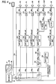
- the audio characteristic control device 10 is equipped with a directionality control unit 210, a delay unit 220, an LPF (lowpass filter) 230, amplification units 241, 242, 243, 244, and 246, a phase inverting unit 250, a filter 260, D/A conversion units 271, 272, 273, 274, 275, and 276, and a gain control unit 280.
- the roles of the respective units will be described below.
- the directionality control unit 210 employs the sum (L + R) of the audio signals L and R as an audio signal MD C to be supplied to the speaker SC, and supplies the audio signal MD C to the amplification units 241 and 246.
- the directionality control unit 210 employs the audio signal L as an audio signal MD L to be supplied to the speaker SL, and supplies the audio signal MD L to the amplification unit 242.
- the directionality control unit 210 employs the audio signal R as an audio signal MD R to be supplied to the speaker SR, and supplies the audio signal MD R to the amplification unit 243.
- the directionality control unit 210 employs the difference L-R between the audio signals L and R as an audio signal MD BL to be supplied to the speaker SBL, and supplies the audio signal MD BL to the delay unit 220.
- the amplification unit 241 amplifies the audio signal MD C supplied from the directionality control unit 210 at a gain g1.
- An audio signal (MD C ⁇ g1) produced through the amplification by the amplification unit 241 is input to the D/A conversion unit 271.
- the D/A conversion unit 271 D/A-converts the audio signal (MD C ⁇ g1) into an analog signal MA C , supplies the analog signal MA C to the speaker SC, and thereby causes the speaker SC to emit a sound M C .
- the amplification unit 242 amplifies the audio signal MD L supplied from the directionality control unit 210 at a gain g2.
- An audio signal (MD L ⁇ g2) produced through the amplification by the amplification unit 242 is input to the D/A conversion unit 272.
- the D/A conversion unit 272 D/A-converts the audio signal (MD L ⁇ g2) into an analog signal MA L , supplies the analog signal MA L to the speaker SL, and thereby causes the speaker SL to emit a sound M L .
- the amplification unit 243 amplifies the audio signal MD R supplied from the directionality control unit 210 at a gain g3.
- An audio signal (MD R ⁇ g3) produced through the amplification by the amplification unit 243 is input to the D/A conversion unit 273.
- the D/A conversion unit 273 D/A-converts the audio signal (MD R ⁇ g3) into an analog signal MA R , supplies the analog signal MA R to the speaker SR, and thereby causes the speaker SR to emit a sound M R .
- the delay unit 220 delays the signal MD BL that is output from the directionality control unit 210 by a delay ⁇ , and outputs a delayed audio signal MD BL '.
- the delay ⁇ of the delay unit 220 may be determined taking into consideration the magnitude of reverberation created in the living room 70 and other factors.
- the output signal MD BL ' of the delay unit 220 is input to the LPF 230.
- the LPF 230 outputs, to the amplification unit 244, a signal MD BL " obtained by eliminating high-frequency components from the audio signal MD BL '.
- the amplification unit 244 amplifies, at a gain g4, the signal MD BL " that is output from the LPF 230.
- An audio signal (MD BL " ⁇ g4) produced through the amplification by the amplification unit 244 is input to the D/A conversion unit 274 and the phase inverting unit 250.
- the D/A conversion unit 274 D/A-converts the audio signal (MD BL " ⁇ g4) into an analog signal MA BL , supplies the analog signal MA BL to the speaker SBL, and thereby causes the speaker SBL to emit a sound M BL .
- the phase inverting unit 250 outputs, to the D/A conversion unit 275, an audio signal MD BR obtained by inverting the phase of the signal (MD BL " ⁇ g4).
- the D/A conversion unit 275 D/A-converts the audio signal MD BR into an analog signal MA BR , supplies the analog signal MA BR to the speaker SBR, and thereby causes the speaker SBR to emit a sound M BR .
- the amplification unit 246 amplifies, at a gain g6, the audio signal MD C that is output from the directionality control unit 210.
- An audio signal (MD C ⁇ g6) produced through the amplification by the amplification unit 246 is input to the filter 2fi0.
- the filter 260 performs, on the signal (MD C ⁇ g6), filtering processing for correcting a feature quantity RH that influences localization in the height direction in a head transfer function H of the viewer P (i.e., a sound transfer function from the center of the ears EL and ER of the viewer P to the external auditory canal inlet (or tympanum) of the viewer P with an assumption that the head of the viewer P is absent).
- the filter 260 outputs a signal MD SF produced through this filtering processing to the D/A conversion unit 276. More specifically, the filter 260 performs filtering processing for forming a dip D RH by attenuating a prescribed component in a frequency range (e.g., 6 to 8 kHz) including the feature quantity RH in the signal (MD C ⁇ g6). And the filter 260 employs, as a signal MD SF , a signal obtained by forming the dip D RH in the signal (MD C x g6).
- a prescribed component in a frequency range e.g. 6 to 8 kHz
- the filter 260 employs, as a signal MD SF , a signal obtained by forming the dip D RH in the signal (MD C x g6).
- the D/A conversion unit 276 D/A-converts the audio signal MD SF into an analog signal MA SF , supplies the analog signal MA SF to the speaker SF, and thereby causes the speaker SF to emit a sound M SF .
- the M SF has an effect of causing the viewer P to feel as if the sound source of the sound M c were near himself or herself, for the following reason.
- a sound M SF that is emitted from the speaker SF which is a planar speaker is much smaller in the rate at which the energy attenuates with the distance than a sound M C that is emitted from the speaker SC which is not a planar speaker, and hence causes almost no difference between a sound pressure of a sound heard at a near listening point and a sound pressure of a sound heard at a distant listening point.
- the viewer P listens to sounds that are emitted from nonplanar speakers.
- the gain control unit 280 is a circuit for controlling the gains g1, g2, g3, g4, and g6 of the amplification units 241, 242, 243, 244, and 246.
- the gain control unit 280 controls the gains g1 and g6 in linkage in such a manner that the relationship of the following Equation (1) holds between the gain g1 of the amplification unit 241 and the gain g6 of the amplification unit 246.
- the gain control unit 280 analyzes the image signal V and calculates a binocular parallax SDF of a display item IO in the image represented by the image signal V.
- the binocular parallax SDF is a parameter for modifying the perceived distance of an object to be displayed to the viewer P and is increased or decreased in accordance with a target distance (more specifically, position in the front-rear direction).
- the gain control unit 280 uses the binocular parallax SDF as a control signal specifying a perceived distance of a sound to be heard by the viewer P, more specifically, a control signal specifying a position in the front-rear direction of a sound source to be perceived by the viewer P.
- the gain control unit 280 employs, as a gain g6 of the amplification unit 246, a value obtained by multiplying the binocular parallax SDF by a coeffcient K1, and sets, as a gain g1 of the amplification unit 241, a value (1 - g6 2 ) 1/2 which is obtained by substituting the gain G6 into the above-mentioned Equation (1).
- the perceived distances of sounds to be heard by the viewer P is controlled by adjusting the balance between the signal levels of audio signals MA C and MA SF to be supplied to the center-channel speaker SC and the planar speaker SF, respectively, among audio signals MA C , MA L , MA R , MA BL , MA SR , and MA SF to be supplied to the plural speakers SC, SL, SR, SBL, SBR, and SF.
- the embodiment makes it possible to localize a sound image of a center-channel sound M c to be sensed by the viewer P at a position that is on the viewer P's side of a reproduction image of the 3D TV receiver RS.
- the distance of the reproduction sound M c of a 3D content that is felt by the viewer P when hearing the sound M C can be controlled so as to match a distance of a display item IO in the reproduction image of the 3D content that is felt by the viewer P when seeing the reproduction image.
- the speaker SF is attached to the ceiling WU over (almost right above) the viewer P. Since the speaker SF is disposed over the viewer P, even if the viewer P turns his or her face in, for example, the left-right direction while viewing a 3D content, the viewer P feels no large difference between part of a sound M SF that reaches the left ear EL and part of the sound M SF that reaches the right ear ER and hence it is difficult for him or her to sense a distance. Therefore, even if the viewer P turns his or her face in, for example, the left-right direction while viewing a 3D content, the viewer P does not realize that the speaker SF exists over himself or herself. As such, the embodiment makes it easier to the control a perceived distance than in a case that the speaker SF is installed at another position.
- the gain control unit 280 controls the gains g1 and g6 in linkage in such a manner that the relationship of the above-mentioned Equation (1) holds between the gain g1 of the amplification unit 241 and the gain g6 of the amplification unit 246.
- This makes it possible to change only the perceived distance of a sound without changing its sound volume as sensed by the viewer P by making a manipulation of, for example, increasing the gain g6 and decreasing the gain g1 accordingly if the distance D is large when a display item IO of a certain scene is viewed three dimensionally or decreasing the gain g6 and increasing the gain g1 accordingly if the distance D is small.
- Fig. 4 is a block diagram showing the confguration of an audio characteristic control device 10A of an audio system according to a second embodiment of the invention.
- the audio characteristic control device 10A is different from the audio characteristic control device 10 (see Fig. 2 ) in that the filter 260 of the latter is replaced by a filter 260A.
- inverse FFT fast Fourier transform
- a sound M SF emitted from the planar speaker SF and a sound M C emitted from the speaker SC can be integrated together more strongly, whereby the accuracy of the perceived distance control can be increased.
- Fig. 5 shows a living room 70 in which an audio system according to a third embodiment of the invention is installed.
- the speaker SF is attached to the wall WF at a position in front of the viewer P.
- the emitting surface of the speaker SF is directed to the viewer P.
- This embodiment can provide the same advantages as the first embodiment.
- the speaker SF is attached to the front wall WF instead of the ceiling WU, the load of work of installing the speaker SF is lighter than in the first embodiment.
- Fig. 6 shows a living room 70 in which an audio system according to a fourth embodiment of the invention is installed.
- a planar speaker SF L is attached to the left wall WL at a position on the left of the viewer P and a planar speaker SF R is attached to the right wall WR at a position on the right of the viewer P.
- the respective emitting surfaces of the speakers SF L and SF R are directed to the viewer P.
- the audio characteristic control device 10 supplies audio signals having the same amplitude and the same phase to the two speakers SF L and SF R .
- This embodiment can provide the same advantages as the first embodiment.
- the speakers SF L and SF R are attached to the respective walls WL and WR instead of the ceiling WU, the load of work of installing the speakers SF L and SF R is lighter than in the first embodiment.
- the gain control unit 280 uses the binocular parallax SDF of a display item IO in an image represented by an image signal V as a control signal specifying a perceived distance of a sound to be heard by the viewer P and controls the gains g1 and g6 of the respective amplification units 241 and 246.
- the viewer P carry a remote controller for specifying a perceived distance of sound manually at will and control the gains g1 and g6 to desired values in accordance with a manipulation result of the remote controller by means of the gain control unit 280.
- a content producing apparatus may be constructed which records, in a recording medium, a control signal generated by manipulating the remote controller together with an image signal and audio signals. More specifically, an image signal V and 2-channel (left and right) audio signals L and R are reproduced and the viewer P is caused to view and listen to resulting video and sound. And a control signal is generated by having the viewer P control the perceived distance to a proper value by manipulating the remote controller.
- the control signal generated as a result of the manipulation of the remote controller and the original image signal V and two (left and right) audio signals L and R are compression-coded, and a resulting compression-coded signal of a 3D video content is recorded in the recording medium.
- the content reproducing device 80 reproduces the control signal together with the image signal V and the 2-channel (left and right) audio signals L and R from the recording medium in a synchronized manner and supplies the reproduced signals to the audio characteristic control device 10 or 10A.
- This mode makes it possible to generate a control signal specifying a perceived distance as a result of a manipulation of the remote controller by the viewer P and produce a 3D video content containing the control signal. As a result, it becomes possible to produce a 3D video content that reflects taste of the viewer P.
- the content reproducing device 80 outputs 2-channel (left and right) audio signals L and R to the audio characteristic control device 10 or 10A.
- the audio characteristic control device 10 or 10A generates 6-channel audio signals MA c , MA L , MA R , MA BL , M BR , and M SF and controls the balance between the signal levels of the audio signal MA C to be supplied to the center-channel speaker SC and the audio signal M SF to be supplied to the planar speaker SF among the audio signals MA C , MA L , MA R , MA BL , M BR , and M SF .
- the content reproducing device 80 may generate 6-channel audio signals MA C , MA L , MA R , MA BL , M BR , and M SF to be supplied to the respective speakers SC, SL, SR, SBL, SBR, and SF and outputs them to the audio characteristic control device 10 or 10A.
- the five speakers SC, SL, SR, SBL, and SBR which are disposed on the floor FF are nonplanar speakers.
- all or part of the speakers SC, SL, SR, SBL, and SBR may be planar speakers.
- all or part of the speakers SC, SL, SR, SBL, and SBR may be an array speaker.
- audio signals MA C , MA L , MA R , MA BL , M BR , and M SF may be emitted toward the viewer P by utilizing reflection of sound beams that are generated by disposing the array speaker in front of (not around) the viewer P.
- the sound propagation distance from the ceiling speaker SF to the viewer P is longer than that from the front speaker SC to the viewer P.
- a configuration as shown in Fig. 7 may be employed in which a delay unit 246D for delaying an audio signal to be supplied to the amplification unit 246 is added so that the arrival of a sound emitted from the front speaker SC to the viewer P is timed with that of a sound emitted from the ceiling speaker SF to the viewer P.
- the balance between the gains g1 and g6 of respective audio signals MA C and MA SF is adjusted by controlling both of the gains g1 and g6.
- the balance between the gains g1 and g6 of respective audio signals MA C and MA SF may be adjusted by making the signal level of the audio signal MA C a fixed value and varying the signal level of the audio signal MA SF or making the signal level of the audio signal MA SF a fixed value and varying the signal level of the audio signal MA C .
- a signal MD C to be supplied to the speaker SC among the five speakers SC, SL, SR, SBL, and SBR disposed on the floor FF is employed as the target of the perceived distance control and a signal MA SF to be supplied to the speaker SF is generated from the signal MD C .
- a signal MA SF to be supplied to the speaker SF may be generated from one of an audio signal MD C to be supplied to the speaker SC, an audio signal MD L to be supplied to the speaker SL, an audio signal MD R to be supplied to the speaker SR, an audio signal MD BL to be supplied to the speaker SBL, and an audio signal MD BR to be supplied to the speaker SBR.
- a signal MA SF to be supplied to the speaker SF may be generated from an addition signal of signals to be supplied to two or more the five speakers SC, SL, SR, SBL, and SBR or an addition signal of all of five kinds of audio signals MD SF , MD L , MD R , MD BL , and MD BR .
- a signal MA SF to be supplied to the speaker SF may be generated from an addition signal (MD L + MD R ) of an audio signal MD L to be supplied to the speaker SL and an audio signal MD R to be supplied to the speaker SR.
- MD L + MD R an addition signal of an audio signal MD L to be supplied to the speaker SL
- MD R an audio signal MD R to be supplied to the speaker SR.
- audio signals to be supplied to plural planar speakers SF may be generated individually.
- a configuration is possible in which two or more planar speakers SF are provided and an audio signal MA SF -1 to be supplied to one planar speaker SF-1 is generated from an audio signal MD L to be supplied to the speaker SL and an audio signal MA SF -2 to be supplied to the other planar speaker SF-2 is generated from an audio signal MD R to be supplied to the speaker SR.
- a signal of a component as a target of the perceived distance control may be extracted from an audio signal MD C to be supplied to the speaker disposed in front of the viewer P and supplied to both of the speaker SC and the planar speaker SF.
- Fig. 8 is a block diagram showing an example configuration of this mode.
- an audio signal MD C is separated by a separation unit 290 into an audio signal MD CA of a component as a target of the perceived distance control and an audio signal MD CB of a component that is not a target of the perceived distance control.
- the audio signal MD CB of the component that is not a target of the perceived distance control is amplified at a prescribed gain by an amplification unit 241 B and supplied to an adder 241C.
- the audio signal MD CA of the component as a target of the perceived distance control is supplied to amplification units 241A and 246.
- the gains of the amplification units 241A and 246 are controlled on the basis of a control signal specifying a perceived distance of sound to be heard by the viewer P.
- An output signal of the amplification unit 241 A is supplied to the adder 241C, and an output signal of the amplification unit 246 is supplied to the D/A conversion unit 276 after being processed by the filter 260.
- An output signal of the D/A conversion unit 276 is supplied to the planar speaker SF and output as a sound.
- the adder 241C outputs, to the D/A conversion unit 271, an addition signal of the output signals of the amplification unit 241A and the audio signal MD CB of the component that is not a target of the perceived distance control.
- An output signal of the D/A conversion unit 271 is supplied to the planar speaker SC and output as a sound.
- an audio signal MD CA of a component as a target of the perceived distance control is extracted from an audio signal MD C to be supplied to the speaker SC and amplified at gains that are determined on the basis of a control signal specifying a perceived distance, and resulting signals are supplied to the respective speakers SC and SF.
- the perceived distance control can be performed on only the particular component of the audio signal MD C to be supplied to the speaker SC.
- the separation unit 290 may have any of various confgurations.
- a bandpass filter may be used which passes an audio signal in a band in which a component of a speech, an effect sound, or the like exists.
- an audio signal to be supplied to the planar speaker SF is generated from audio signals to be supplied to, for example, the front-left speaker SL and the front-right speaker SR as in Modification (7), only a signal of a component as a target of the perceived distance control may be extracted from each audio signal and supplied to both speakers.
- a filter coefficient sequence corresponding to a function that is the reciprocal of a head transfer function H may be convoluted.
- a filter coefficient sequence corresponding to a function that is the reciprocal of a transfer function (HA + H) which is the sum of the transfer function HA and the head transfer function H may be convoluted.
- the perceived distance control of a sound to be heard by the viewer P is performed using the combination of the planar speaker SF and the nonplanar speaker SC.
- a configuration is possible in which the speaker SC is replaced by a speaker (planar speaker) SCF which emits a plane wave and the perceived distance control is performed using the combination of the two speakers (planar speakers) SF and SCF which emit plane waves toward the viewer P from different directions.
- the configuration which uses the combination of the planar speaker SF and the nonplanar speaker SC as shown in Fig.
- the perceived distance control can be performed in a range D from a position in the vicinity of the speaker SC to a position in the vicinity of the viewer P.
- the perceived distance control can be performed in a range D' which is on the side of the viewer P and narrower than the range D.
- Figs. 10 and 11 show an example configuration according to this mode.
- planar speakers SFL and SFR are attached to the ceiling above the viewer P. The positions of the planar speakers SFL and SFR are determined so that a sound emitted from the planar speaker SFL reaches the left ear but does not reach his or her right ear and a sound emitted from the planar speaker SFR reaches the right ear but does not reach his or her left ear.
- the speaker SL which is disposed on the front-left of the viewer P emits a sound toward the left ear of the viewer P.
- the speaker SR which is disposed on the front-right of the viewer P emits a sound toward the right ear of the viewer P.
- Fig. 11 shows the configuration of a signal processing system which supplies audio signals to the speakers SL and SR and planar speakers SFL and SFR.
- an audio signal MD L is supplied to the speaker SL after being processed by an amplification unit 242L and a D/A conversion unit 272L and is also supplied to the planar speaker SFL after being processed by an amplification unit 246L, a filter 260L, and a D/A conversion unit 276L.
- an audio signal MD R is supplied to the speaker SR after being processed by an amplification unit 243L and a D/A conversion unit 273L and is also supplied to the planar speaker SFR after being processed by an amplification unit 246R, a filter 260R, and a D/A conversion unit 276R.
- the audio signals MD L and MD R are an L-channel audio signal and an R-channel audio signal, respectively, that are reproduced from the decoder 12 used in the first embodiment.
- the filters 260L and 260R are filters having the same function as the filter 60 used in the first embodiment or the filter 260A used in the second embodiment.
- the gains of the amplification units 243L and 246L are controlled in accordance with a control signal specifying a perceived distance of a sound to be heard by the left ear of the viewer P.
- the gains of the amplification units 243R and 246R are controlled in accordance with a control signal specifying a perceived distance of a sound to be heard by the right ear of the viewer P.
- control signals specifying perceived distances are compression-coded and recorded in a recording medium together with audio signals of the respective channels and a video signal.
- the control signals specifying perceived distances are reproduced from the recording medium together with the audio signals of the respective channels and a video signal in a synchronized manner and used for controlling the gains of the amplification units 242L, 246L, 243R, and 246R.
- these control signals specifying perceived distances are generated by manipulating respective manipulation members.
- speakers SL and SR may be replaced by planar speakers.
- separation units as described in the above Modification (8) may be provided.
- this confguration only a signal of a component as a target of the perceived distance control is extracted from the audio signal MD L and supplied to both of the planar speakers SFL and SL and only a signal of a component as a target of the perceived distance control is extracted from the audio signal MD R and supplied to both of the planar speakers SFR and SR.
- the speakers SC, SL, SR, SBL, and SBR of the surround system are disposed on the floor or walls of a living room around the viewer P.
- the content reproducing device 80 outputs an audio signal MA CH1 to be supplied to the speaker SC, an audio signal MA CH2 to be supplied to the speaker SL, an audio signal MA CH3 to be supplied to the speaker SR, an audio signal MA CH4 to be supplied to the speaker SBL, and an audio signal MA CH5 to be supplied to the speaker SR.
- the surround control device 1200 amplifies, at gains specific to the respective signals, the 5-channel signals MA CH1 , MA CH2 , MA CH3 , MA CH4 , and MA CH5 which are output from the content reproducing device 80, and supplies the speakers SC, SL, SR, SBL, and SBR with signals MA CH1 ', MA CH2 ', MA CH3 '.
- MA CH4 ', and MA CH5 ' whose signal levels have been adjusted through the amplification.
- the planar speaker SF of the audio system is disposed over (almost right above) the viewer P in the living room.
- the audio characteristic control device 10B is equipped with an amplification unit 1230.
- the audio characteristic control device 10B takes in the signal MA CH1 among the audio signals MA CH1 , MA CH2 , MA CH3 , MA CH4 , and MA CH5 which are output from the content reproducing device 80, amplifies the signal MA CH1 at a gain specific to it, and supplies the planar speaker SH with a signal MA CH1 whose signal level has been adjusted through the amplification.
- the gain at which the signal MA CH1 , is amplified is controlled on the basis of a control signal specifying a perceived distance.
- a control signal specifying a perceived distance for example, as in the first embodiment, an image signal V reproduced from the content reproducing device 80 is analyzed and a binocular parallax SDF of a display item IO in an image represented by the signal V is calculated.
- the calculated binocular parallax SDF may be used as a control signal specifying a perceived distance.
- a control signal specifying a perceived distance may be generated by manipulating a remote controller.
- the invention makes can provide an audio system which can control the distance of sound a listener feels when hearing sound emitted from speakers.
- 10 Audio characteristic control device; 11 ⁇ Optical drive; 12 ⁇ Decoder; 210 ⁇ Directionality control unit; 220 ⁇ Delay unit; 230 ⁇ LPF; 241, 242, 242L, 243, 243R, 244, 246, 246L, 246R, ⁇ Amplification unit; 250 ⁇ Phase inverting unit; 260 ⁇ Filter; 271, 272, 272L, 273, 273R, 274, 275, 276, 276L, 276R ⁇ D/A conversion unit; 280 ⁇ Gain control unit; 80 ⁇ Content reproducing device; 81 ⁇ TV rack; 90 ⁇ Storage medium.
Applications Claiming Priority (3)
| Application Number | Priority Date | Filing Date | Title |
|---|---|---|---|
| JP2011131964 | 2011-06-14 | ||
| JP2012128450A JP5988710B2 (ja) | 2011-06-14 | 2012-06-05 | 音響システム及び音響特性制御装置 |
| PCT/JP2012/065271 WO2012173201A1 (fr) | 2011-06-14 | 2012-06-14 | Système audio et dispositif de contrôle de caractéristique audio |
Publications (2)
| Publication Number | Publication Date |
|---|---|
| EP2723104A1 true EP2723104A1 (fr) | 2014-04-23 |
| EP2723104A4 EP2723104A4 (fr) | 2014-11-05 |
Family
ID=47357182
Family Applications (1)
| Application Number | Title | Priority Date | Filing Date |
|---|---|---|---|
| EP12800891.9A Withdrawn EP2723104A4 (fr) | 2011-06-14 | 2012-06-14 | Système audio et dispositif de contrôle de caractéristique audio |
Country Status (4)
| Country | Link |
|---|---|
| US (1) | US9351074B2 (fr) |
| EP (1) | EP2723104A4 (fr) |
| JP (1) | JP5988710B2 (fr) |
| WO (1) | WO2012173201A1 (fr) |
Families Citing this family (3)
| Publication number | Priority date | Publication date | Assignee | Title |
|---|---|---|---|---|
| JP7160312B2 (ja) * | 2018-07-17 | 2022-10-25 | 学校法人大阪産業大学 | 音響システム |
| CN115762579A (zh) * | 2018-09-29 | 2023-03-07 | 华为技术有限公司 | 一种声音处理方法、装置与设备 |
| US20230056690A1 (en) * | 2020-01-10 | 2023-02-23 | Sony Group Corporation | Encoding device and method, decoding device and method, and program |
Citations (3)
| Publication number | Priority date | Publication date | Assignee | Title |
|---|---|---|---|---|
| US5440639A (en) * | 1992-10-14 | 1995-08-08 | Yamaha Corporation | Sound localization control apparatus |
| JP2004168265A (ja) * | 2002-11-22 | 2004-06-17 | Fujitsu Ten Ltd | 車載用スピーカ装置 |
| US20110069850A1 (en) * | 2007-08-14 | 2011-03-24 | Koninklijke Philips Electronics N.V. | Audio reproduction system comprising narrow and wide directivity loudspeakers |
Family Cites Families (13)
| Publication number | Priority date | Publication date | Assignee | Title |
|---|---|---|---|---|
| GB9107011D0 (en) | 1991-04-04 | 1991-05-22 | Gerzon Michael A | Illusory sound distance control method |
| JP3160342B2 (ja) | 1992-01-13 | 2001-04-25 | 株式会社リコー | 超音波駆動装置 |
| EP1749420A4 (fr) * | 2004-05-25 | 2008-10-15 | Huonlabs Pty Ltd | Dispositif et procede audio |
| JP2006092482A (ja) * | 2004-09-27 | 2006-04-06 | Yamaha Corp | 音声認識通報装置 |
| DE102004057500B3 (de) | 2004-11-29 | 2006-06-14 | Fraunhofer-Gesellschaft zur Förderung der angewandten Forschung e.V. | Vorrichtung und Verfahren zur Ansteuerung einer Beschallungsanlage und Beschallungsanlage |
| US7995768B2 (en) | 2005-01-27 | 2011-08-09 | Yamaha Corporation | Sound reinforcement system |
| JP4196956B2 (ja) * | 2005-02-28 | 2008-12-17 | ヤマハ株式会社 | 拡声システム |
| JP2007028066A (ja) * | 2005-07-14 | 2007-02-01 | Victor Co Of Japan Ltd | オーディオ再生システム |
| JP2009077379A (ja) * | 2007-08-30 | 2009-04-09 | Victor Co Of Japan Ltd | 立体音響再生装置、立体音響再生方法及びコンピュータプログラム |
| JP5075023B2 (ja) * | 2008-06-18 | 2012-11-14 | パナソニック株式会社 | 音響システム |
| JP2010050875A (ja) * | 2008-08-25 | 2010-03-04 | Sony Corp | イコライザ装置、周波数特性付加方法、周波数特性付加プログラムおよび音響再生装置 |
| JP4706740B2 (ja) * | 2008-09-05 | 2011-06-22 | マツダ株式会社 | 車両用運転支援装置 |
| US8212659B2 (en) | 2008-09-05 | 2012-07-03 | Mazda Motor Corporation | Driving assist device for vehicle |
-
2012
- 2012-06-05 JP JP2012128450A patent/JP5988710B2/ja active Active
- 2012-06-14 WO PCT/JP2012/065271 patent/WO2012173201A1/fr unknown
- 2012-06-14 EP EP12800891.9A patent/EP2723104A4/fr not_active Withdrawn
-
2013
- 2013-12-12 US US14/105,054 patent/US9351074B2/en active Active
Patent Citations (3)
| Publication number | Priority date | Publication date | Assignee | Title |
|---|---|---|---|---|
| US5440639A (en) * | 1992-10-14 | 1995-08-08 | Yamaha Corporation | Sound localization control apparatus |
| JP2004168265A (ja) * | 2002-11-22 | 2004-06-17 | Fujitsu Ten Ltd | 車載用スピーカ装置 |
| US20110069850A1 (en) * | 2007-08-14 | 2011-03-24 | Koninklijke Philips Electronics N.V. | Audio reproduction system comprising narrow and wide directivity loudspeakers |
Non-Patent Citations (1)
| Title |
|---|
| See also references of WO2012173201A1 * |
Also Published As
| Publication number | Publication date |
|---|---|
| WO2012173201A1 (fr) | 2012-12-20 |
| JP5988710B2 (ja) | 2016-09-07 |
| US20140105429A1 (en) | 2014-04-17 |
| US9351074B2 (en) | 2016-05-24 |
| JP2013021686A (ja) | 2013-01-31 |
| EP2723104A4 (fr) | 2014-11-05 |
Similar Documents
| Publication | Publication Date | Title |
|---|---|---|
| EP3095254B1 (fr) | Impression spatiale améliorée pour audio domestique | |
| JP4743790B2 (ja) | 前方配置ラウドスピーカからのマルチチャネルオーディオサラウンドサウンドシステム | |
| US20140153765A1 (en) | Listening Device and Accompanying Signal Processing Method | |
| CN1829393B (zh) | 产生用于双声道头戴耳机的立体声的方法和设备 | |
| US20160295342A1 (en) | Audio reproduction apparatus and game apparatus | |
| JP2004187300A (ja) | 指向性電気音響変換 | |
| JP2011244431A (ja) | 音響信号の個別化 | |
| AU5666396A (en) | A four dimensional acoustical audio system | |
| JP2000092578A (ja) | スピーカ装置 | |
| JP4904461B2 (ja) | 音声周波数応答処理システム | |
| CN107925814A (zh) | 生成提升声音印象的方法和设备 | |
| US9351074B2 (en) | Audio system and audio characteristic control device | |
| CN107743713B (zh) | 处理用于在汽车中再现的立体声信号以通过前置扬声器实现单独的三维声音的装置和方法 | |
| Tan et al. | Spatial sound reproduction using conventional and parametric loudspeakers | |
| US9872121B1 (en) | Method and system of processing 5.1-channel signals for stereo replay using binaural corner impulse response | |
| JP2005535217A (ja) | オーディオ処理システム | |
| EP3530006B1 (fr) | Appareil et procédé de pondération de signaux audio stéréo | |
| Linkwitz | The magic in 2-channel sound reproduction—Why is it so rarely heard? | |
| Corteel et al. | Objective and subjective comparison of electrodynamic and map loudspeakers for wave field synthesis | |
| JP2006352728A (ja) | オーディオ装置 | |
| US9402143B2 (en) | Method for processing an audio signal, audio playback system, and processing unit for processing audio signals | |
| US20210409866A1 (en) | Loudspeaker System with Overhead Sound Image Generating (e.g., ATMOS™) Elevation Module and Method and apparatus for Direct Signal Cancellation | |
| CN101014210B (zh) | 音频再现系统及其方法 | |
| JPH08140200A (ja) | 立体音像制御装置 | |
| Schobben et al. | Personalized multi-channel headphone sound reproduction based on active noise cancellation |
Legal Events
| Date | Code | Title | Description |
|---|---|---|---|
| PUAI | Public reference made under article 153(3) epc to a published international application that has entered the european phase |
Free format text: ORIGINAL CODE: 0009012 |
|
| 17P | Request for examination filed |
Effective date: 20131213 |
|
| AK | Designated contracting states |
Kind code of ref document: A1 Designated state(s): AL AT BE BG CH CY CZ DE DK EE ES FI FR GB GR HR HU IE IS IT LI LT LU LV MC MK MT NL NO PL PT RO RS SE SI SK SM TR |
|
| DAX | Request for extension of the european patent (deleted) | ||
| A4 | Supplementary search report drawn up and despatched |
Effective date: 20141002 |
|
| RIC1 | Information provided on ipc code assigned before grant |
Ipc: H04R 3/12 20060101ALI20140926BHEP Ipc: H04S 7/00 20060101AFI20140926BHEP Ipc: H04R 19/02 20060101ALN20140926BHEP |
|
| STAA | Information on the status of an ep patent application or granted ep patent |
Free format text: STATUS: THE APPLICATION HAS BEEN WITHDRAWN |
|
| 18W | Application withdrawn |
Effective date: 20180314 |