EP2722432B1 - Clothes treating apparatus with heat pump and control method thereof - Google Patents
Clothes treating apparatus with heat pump and control method thereof Download PDFInfo
- Publication number
- EP2722432B1 EP2722432B1 EP13189197.0A EP13189197A EP2722432B1 EP 2722432 B1 EP2722432 B1 EP 2722432B1 EP 13189197 A EP13189197 A EP 13189197A EP 2722432 B1 EP2722432 B1 EP 2722432B1
- Authority
- EP
- European Patent Office
- Prior art keywords
- heating medium
- temperature
- heat pump
- heating
- pressure
- Prior art date
- Legal status (The legal status is an assumption and is not a legal conclusion. Google has not performed a legal analysis and makes no representation as to the accuracy of the status listed.)
- Not-in-force
Links
Images


Classifications
-
- D—TEXTILES; PAPER
- D06—TREATMENT OF TEXTILES OR THE LIKE; LAUNDERING; FLEXIBLE MATERIALS NOT OTHERWISE PROVIDED FOR
- D06F—LAUNDERING, DRYING, IRONING, PRESSING OR FOLDING TEXTILE ARTICLES
- D06F58/00—Domestic laundry dryers
- D06F58/20—General details of domestic laundry dryers
- D06F58/206—Heat pump arrangements
-
- D—TEXTILES; PAPER
- D06—TREATMENT OF TEXTILES OR THE LIKE; LAUNDERING; FLEXIBLE MATERIALS NOT OTHERWISE PROVIDED FOR
- D06F—LAUNDERING, DRYING, IRONING, PRESSING OR FOLDING TEXTILE ARTICLES
- D06F58/00—Domestic laundry dryers
- D06F58/02—Domestic laundry dryers having dryer drums rotating about a horizontal axis
- D06F58/04—Details
-
- D—TEXTILES; PAPER
- D06—TREATMENT OF TEXTILES OR THE LIKE; LAUNDERING; FLEXIBLE MATERIALS NOT OTHERWISE PROVIDED FOR
- D06F—LAUNDERING, DRYING, IRONING, PRESSING OR FOLDING TEXTILE ARTICLES
- D06F58/00—Domestic laundry dryers
- D06F58/32—Control of operations performed in domestic laundry dryers
- D06F58/34—Control of operations performed in domestic laundry dryers characterised by the purpose or target of the control
- D06F58/36—Control of operational steps, e.g. for optimisation or improvement of operational steps depending on the condition of the laundry
- D06F58/38—Control of operational steps, e.g. for optimisation or improvement of operational steps depending on the condition of the laundry of drying, e.g. to achieve the target humidity
-
- D—TEXTILES; PAPER
- D06—TREATMENT OF TEXTILES OR THE LIKE; LAUNDERING; FLEXIBLE MATERIALS NOT OTHERWISE PROVIDED FOR
- D06F—LAUNDERING, DRYING, IRONING, PRESSING OR FOLDING TEXTILE ARTICLES
- D06F2103/00—Parameters monitored or detected for the control of domestic laundry washing machines, washer-dryers or laundry dryers
- D06F2103/28—Air properties
- D06F2103/30—Pressure
-
- D—TEXTILES; PAPER
- D06—TREATMENT OF TEXTILES OR THE LIKE; LAUNDERING; FLEXIBLE MATERIALS NOT OTHERWISE PROVIDED FOR
- D06F—LAUNDERING, DRYING, IRONING, PRESSING OR FOLDING TEXTILE ARTICLES
- D06F2103/00—Parameters monitored or detected for the control of domestic laundry washing machines, washer-dryers or laundry dryers
- D06F2103/28—Air properties
- D06F2103/32—Temperature
-
- D—TEXTILES; PAPER
- D06—TREATMENT OF TEXTILES OR THE LIKE; LAUNDERING; FLEXIBLE MATERIALS NOT OTHERWISE PROVIDED FOR
- D06F—LAUNDERING, DRYING, IRONING, PRESSING OR FOLDING TEXTILE ARTICLES
- D06F2103/00—Parameters monitored or detected for the control of domestic laundry washing machines, washer-dryers or laundry dryers
- D06F2103/50—Parameters monitored or detected for the control of domestic laundry washing machines, washer-dryers or laundry dryers related to heat pumps, e.g. pressure or flow rate
-
- D—TEXTILES; PAPER
- D06—TREATMENT OF TEXTILES OR THE LIKE; LAUNDERING; FLEXIBLE MATERIALS NOT OTHERWISE PROVIDED FOR
- D06F—LAUNDERING, DRYING, IRONING, PRESSING OR FOLDING TEXTILE ARTICLES
- D06F2105/00—Systems or parameters controlled or affected by the control systems of washing machines, washer-dryers or laundry dryers
- D06F2105/26—Heat pumps
-
- D—TEXTILES; PAPER
- D06—TREATMENT OF TEXTILES OR THE LIKE; LAUNDERING; FLEXIBLE MATERIALS NOT OTHERWISE PROVIDED FOR
- D06F—LAUNDERING, DRYING, IRONING, PRESSING OR FOLDING TEXTILE ARTICLES
- D06F2105/00—Systems or parameters controlled or affected by the control systems of washing machines, washer-dryers or laundry dryers
- D06F2105/28—Electric heating
-
- D—TEXTILES; PAPER
- D06—TREATMENT OF TEXTILES OR THE LIKE; LAUNDERING; FLEXIBLE MATERIALS NOT OTHERWISE PROVIDED FOR
- D06F—LAUNDERING, DRYING, IRONING, PRESSING OR FOLDING TEXTILE ARTICLES
- D06F34/00—Details of control systems for washing machines, washer-dryers or laundry dryers
- D06F34/14—Arrangements for detecting or measuring specific parameters
- D06F34/26—Condition of the drying air, e.g. air humidity or temperature
-
- D—TEXTILES; PAPER
- D06—TREATMENT OF TEXTILES OR THE LIKE; LAUNDERING; FLEXIBLE MATERIALS NOT OTHERWISE PROVIDED FOR
- D06F—LAUNDERING, DRYING, IRONING, PRESSING OR FOLDING TEXTILE ARTICLES
- D06F58/00—Domestic laundry dryers
- D06F58/20—General details of domestic laundry dryers
- D06F58/26—Heating arrangements, e.g. gas heating equipment
-
- D—TEXTILES; PAPER
- D06—TREATMENT OF TEXTILES OR THE LIKE; LAUNDERING; FLEXIBLE MATERIALS NOT OTHERWISE PROVIDED FOR
- D06F—LAUNDERING, DRYING, IRONING, PRESSING OR FOLDING TEXTILE ARTICLES
- D06F58/00—Domestic laundry dryers
- D06F58/32—Control of operations performed in domestic laundry dryers
- D06F58/34—Control of operations performed in domestic laundry dryers characterised by the purpose or target of the control
Definitions
- the present disclosure relates to a clothes treating apparatus having a heat pump and an operation method thereof, and more particularly, to a clothes treating apparatus having a heat pump and a heating unit and a control method thereof.
- a clothes treating apparatus having dry performance like a washing machine or a dryer is an apparatus in which the laundry, in a state in which the laundry has been completely washed and spin-dried, is put into a drum and hot wind is supplied to the interior of the drum to evaporate moisture of the laundry to dry it.
- a drum is rotatably installed within a body and receiving the laundry put thereto, a driving motor for driving the drum, a blower blowing air into the drum, and a heating unit for heating air introduced to the interior of the drum.
- the heating unit may use electrical resistance heat having a high temperature generated by using electrical resistance or may use combustion generated by burning gas.
- dryers may be classified into a condensing type dryer (or circulating dryer) and an exhaust-type dryer according to the way in which air of high temperature and humidity is treated.
- a condensing type dryer air of high temperature and humidity is circulated, rather than being discharged to the outside, so as to be cooled to have a temperature lower than a dew-point temperature, thus condensing moisture included in the air of high temperature and humidity.
- the exhaust-type dryer air of high temperature and humidity which has passed through the drum is directly discharged to the outside.
- the exhaust-type dryer it is required to discharge air of high temperature and humidity to the outside, introduce ambient air having room temperature, and heat the introduced ambient air to reach a required temperature level through a heating unit.
- air of high temperature discharged to the outside contains thermal energy transmitted by the heating unit, but since it is discharged to the outside, heat efficiency is degraded.
- a clothes treating apparatus capable of enhancing energy efficiency by recovering energy required for generating hot air and energy discharged to the outside, without being used has been presented.
- a clothes treating apparatus having a heat pump has been introduced.
- the heat pump having two heat exchangers, a compressor, and an expander, recovers energy of exhaust hot air and reuse it to heat air supplied to a drum, thus increasing energy efficiency.
- the heat pump transmits thermal energy of air of high temperature and humidity introduced from the drum through the evaporator to a refrigerant, and transmits thermal energy of the refrigerant to air flowing into the drum through the condenser, thereby generating hot air by using discarded energy.
- the use of heat pump enhances energy efficiency in comparison to the case in which drying is performed by using a heater.
- US 2012/017466 A1 and US 2012/017465 A1 each describe a heat pump type clothes dryer having an evaporator, a condenser, and a compressor.
- a temperature or pressure sensor is located in the center of the condenser and is coupled to a controller, which controls an auxiliary heater.
- WO 2012/134148 A2 describes a dryer having a heat pump system including a first heat exchanger for absorbing waste heat from air discharged out of a drum, a compressor, and a second heat exchanger for heating air introduced into the drum.
- a temperature sensor is installed at an inlet side of the first heat exchanger, and a temperature sensor is installed at an outlet side thereof.
- a further temperature sensor is disposed at the outlet side of the compressor.
- This dryer comprises further a heater as an auxiliary heat source which can be selectively turned on or off. When a temperature variation of the refrigerant at the outlet side of the compressor after driving the heater is smaller than a pre-set reference temperature variation, the control unit of the dryer turns the heater off.
- DE 43 04 226 A1 describes a dryer having a heat pump including an evaporator, a condenser and a refrigerant pipe.
- a temperature sensor monitors a temperature of a refrigerant flowing in the refrigerant pipe.
- DE 10 2007 016076 A1 describes a laundry dryer having a heat pump including an evaporator, a compressor, and a condenser.
- the dryer has a temperature sensor for measuring a temperature of a refrigerant.
- hot air may be generated by using both the heat pump and the heating unit.
- both the heat pump and the heating unit air can be quickly heated, in comparison to a case in which only the heat pump is actuated, shortening a drying time but increasing energy consumption to degrade energy efficiency.
- the heating unit is operated together with the heat pump during a drying process, a time for a refrigerant to reach evaporation pressure in an evaporator of the heat pump is shortened, increasing pressure of a compressor driving unit of the heat pump.
- an aspect of the invention is to provide a clothes treating apparatus and a method for controlling a clothes treating apparatus capable of increasing energy efficiency when a heat pump and a heating unit are operated together during a drying process and controlling power of the heating unit on the basis of at least one current physical parameter value of a heating medium, such as a refrigerant, circulating in the heat pump.
- a heating medium such as a refrigerant
- Another aspect of the present invention is to provide a clothes treating apparatus and a method for controlling a clothes treating apparatus capable of preventing damage to a heat pump when the heat pump and a heating unit are operated together during a drying process and controlling power of the heating unit on the basis of at least one current physical parameter value of a heating medium circulating in the heat pump.
- the clothes treating apparatus includes: a drum for accommodating a dry target; a heat pump configured to cool air transmitted from the drum and subsequently heat the same; a heating unit configured to heat air transmitted from the heat pump to the drum; a sensing unit configured to sense at least one physical parameter value of a heating medium in the heat pump; and a control unit configured to control the heating unit on the basis of the physical parameter value of the heating medium.
- the heat pump includes a heating medium that circulates; a compressor configured to compress the heating medium; a condenser configured to heat air transmitted to the drum; an expander configured to expand the heating medium; and an evaporator configured to cool air transmitted from the drum.
- the control of power of the heating unit may include switching off the heating unit, so that only the heat pump is operated.
- the heating unit is switched off under a condition of the heating medium indicating that a stable state of heating has been reached.
- the object of fast heating has been achieved and a heating using only the heat pump may be sufficient.
- the control unit when a variation in the physical parameter value (e.g. temperature, pressure) is reduced compared with an initial variation in the physical parameter value of the heating medium by more than a predetermined numerical value, the control unit is configured to cut off power of the heating unit. That is, if (initial variation) - (current variation) > a, the heater is switched off.
- the control unit may be configured to cut off power of the heating unit. That is, if (current value) - (previous value) ⁇ b, and/or (previous variation) - (current variation) ⁇ c, the heater is switched off.
- the control unit may be configured to operate the heating unit and the heat pump simultaneously or only one thereof. During hot air supply to the drum, the heating unit is preferably switched off, if a desired drum temperature is reached. Thus, the control unit may be configured to power off the heating unit, if the drum temperature is equal to or higher than a predetermined value.
- the sensing unit includes at least one temperature sensing unit and may include at least one pressure sensing unit for sensing the temperature, and preferably pressure, of the heating medium in the heat pump.
- the control unit controls the heating unit based on a temperature of the heating medium, and preferably on a pressure, of the heating medium.
- a temperature sensing unit may be arranged in a first connection pipe in which the heating medium flows from the compressor to the condenser.
- the temperature sensing unit may be installed to be adjacent to the compressor to sense a temperature of the heating medium discharged from the compressor.
- the condenser may include a condenser heating medium pipe in which the heating medium flows.
- a temperature sensing unit may be arranged in the condenser heating medium pipe.
- the temperature sensing unit is provided in the halfway point of the condenser heating medium pipe, i.e. in a middle portion along the condensor heating medium pipe. Therefore a temperature of the heating medium appropriately heat-exchanged in the condenser may be sensed.
- control unit may cut off power of the heating unit. By these means, damage of the heat pump may be prevented.
- the temperature of the heating medium may be used as a measure for the drum temperature.
- the control unit may cut off power of the heating unit.
- the control unit may cut off power of the heating unit.
- the term temperature variation may refer to a temperature average between two points in time, i.e. the difference of the temperatures sensed at these two time points divided by the time interval there between, or a gradient, i.e. slope, of the temperature curve (temperature vs. time).
- the heating unit may be switched off. In this situation, the heating operation has reached a stable state, in which the temperature of the heating medium remains nearly constant. Therefore, the additional heating by the heating unit used for increased heating rate is not necessary any longer. By these means, the heat efficiency of the laundry treatment apparatus can be optimized.
- a pressure sensing unit may be arranged in at least one of a first connection pipe in which the heating medium flows from the compressor to the condenser, a condenser heating medium pipe in which the heating medium flows in the condenser, and a second connection pipe in which the heating medium flows from the condenser to the expander.
- control unit may cut off power of the heating unit. By these means, damage of the heat pump may be prevented.
- the pressure of the heating medium may be used as a measure for the drum temperature.
- the control unit may cut off power of the heating unit.
- the control unit may cut off power of the heating unit.
- the slope of the temperature curve (temperature vs. time) flattens below a predetermined value or if a difference between the current slope and a previous slope is less than a predetermined value, the heating unit may be switched off. In this situation, the heating operation has reached a stable state, in which the pressure of the heating medium remains nearly constant. Therefore, the additional heating by the heating unit used for increased heating rate is not necessary any longer. By these means, the heat efficiency of the laundry treatment apparatus can be optimized.
- the initial temperature variation and/or previous pressure variation may refer to a respective initial variation measured after powering up the heat pump, e.g. after a predetermined time t1. This value may be stored in a memory.
- the previous temperature variation and/or previous pressure variation may refer to the respective value measured before a current temperature variation and/or current pressure variation.
- the temperature variation and/or pressure variation may be determined repeatedly, and a difference between two subsequent temperature variations and/or pressure variations may be used for comparison with a predetermined value. If this difference is lower than the predetermined value, the heating unit may be switched off.
- a method for controlling a clothes treating apparatus having a heat pump and a heating unit includes: a hot air supplying operation of supplying hot air to a drum by applying power to a heat pump and a heating unit; a sensing operation of sensing at least one physical parameter value of a heating medium that circulates in the heat pump; and a heating unit control operation of controlling power of the heating unit on the basis of the physical parameter value of the heating medium.
- the method may be used by a control unit in a clothes treating apparatus according to any one of the above described embodiments.
- the heat pump and the heating unit are operated simultaneously.
- the physical parameter value of a heating medium comprises a temperature, and preferably further a pressure, of the heating medium.
- heating unit when a temperature and/or a pressure of the heating medium is equal to or greater than a respective predetermined numerical value, heating unit may be switched off. Alternatively or additionally, in the heating unit control operation, when a temperature variation and/or a pressure variation of the heating medium is reduced from a previous temperature variation and/or pressure variation of the heating medium by more than a predetermined numerical value, power of the heating unit may be cut off.
- a temperature of the heating medium comprises at least a temperature of the heating medium discharged from a compressor of the heat pump and may comprise a temperature of the heating medium that flows within a condenser of the heat pump.
- a pressure of the heating medium may comprise at least one of a pressure of the heating medium that flows from the compressor of the heat pump to the condenser of the heat pump, a pressure of the heating medium that flows within the condenser, and a pressure of the heating medium that flows from the condenser of the heat pump to an expander of the heat pump
- the laundry can be quickly dried by actuating both the heat pump and the heating unit simultaneously and/or alternately, and since the heating unit is controlled on the basis of a value of one or more physical parameters and/or on the basis of a change of one or more physical parameters, i.e. in material properties of a heating medium, energy efficiency can be enhanced.
- the heating medium is prevented from being overheated by controlling the heating unit according to the physical properties of the heating medium and/or a change thereof, durability of the heat pump can be enhanced.
- a point in time at which power of the heating unit is to be controlled may be determined based on pressure and/or temperature of the heating medium, an ON/OFF operation of the heating unit can be precisely controlled.
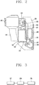
- FIG. 1 is a perspective view schematically illustrating an internal structure of a clothes treating apparatus according to an embodiment of the present invention.
- FIG. 2 is a view schematically illustrating a configuration of a heat pump and a sensing unit of the clothes treating apparatus illustrated in FIG. 1 .
- FIG. 3 is a block diagram schematically illustrating a configuration for controlling a heating unit of the clothes treating apparatus illustrated in FIG. 2 .
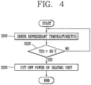
- FIG. 4 is a flow diagram illustrating a process of controlling the heating unit according to a temperature by a control unit of the clothes treating apparatus illustrated in FIG. 3 .
- FIGS. 1 through 4 The embodiment of the present invention illustrated in FIGS. 1 through 4 is applied to a dryer, but the present invention is not limited only to a dryer and may also be applicable to a certain clothes treating apparatus for drying the laundry by supplying hot air into a drum, e.g., a washing machine having a dry function, and the like.
- the clothes treating apparatus includes a body 100 forming the exterior and a drum 110 rotatably installed within the body 100.
- the drum is rotatably supported by a supporter (not shown) in front and rear sides.
- the body 100 includes a door for opening and closing one side of the drum 110 to allow a drying target (or a drying object) to be put into the drum 110. Also, the body 100 may include a display unit displaying information such as a drying process mode, a drying progress degree, real-time energy efficiency, and the like, when a drying process is performed.
- An intake duct 120 forming part of a flow path for transmitting air to the interior of the drum 110 is installed at a lower portion of the drum 110.
- An end portion of the intake duct 120 is connected to an end portion of a back duct 122.
- the back duct 122 extends in a vertical direction of the body 100 between the intake duct 120 and the drum 110 to supply air, which has passed through the intake duct 120, to the interior of the drum 110.
- a flow path transmitting air to the drum 110 is formed by the intake duct 120 and the back duct 122.
- Air supplied through the flow path is introduced from the outside into the body 100 through an intake port (not shown), e.g. formed in a rear surface or at a lower portion of the body 100, and transferred to the intake duct 120.
- an intake fan 185 may be installed in an end portion of the intake duct 120. Namely, according to rotation of the intake fan 185, air staying within the body 100 is introduced to the intake duct 120, and accordingly, pressure within the body 100 is lowered to allow ambient air to be introduced into the body 100 through the intake port.
- a condenser 130 is installed in front of the fan (i.e., in an upper stream side on the basis of an air flow path).
- the condenser 130 together with an evaporator 135, a compressor 150, and an expander 160 as described hereinafter, constitutes a heat pump.
- the heat pump includes a heating medium circulating within the heat pump. The heating medium is compressed by the compressor 150 and subsequently supplied to the condenser 130 through a first connection pipe 191 connecting the compressor 150 and the condenser 130.
- the heating medium emits heat in the condenser 130 and is subsequently supplied to the expander 160 through a second connection pipe 192 connecting the condenser 130 and the expander 160.
- the heating medium expanded by the expander 160 is supplied to an evaporator 135 through a third connection pipe 193 connecting the expander 160 and the evaporator 135.
- the heating medium absorbs heat in the evaporator 135 and is subsequently supplied to the compressor 150 through a fourth connection pipe 194 connecting the evaporator 135 and the compressor 150. In this manner, the heating medium circulates in the heat pump.
- a heating medium acts as a refrigerant in the evaporator 135, so a heating medium will be referred to as a refrigerant.
- a single refrigerant pipe 134 as a condenser heating medium pipe is disposed in a winding or meandering manner, and a plurality of heat dissipation fins 132 are installed perpendicular to the plane of the air flow path in the refrigerant pipe 134. Namely, the refrigerant pipe 134 penetrates through the heat dissipation fins 132 disposed in piles (or in layers) at predetermined intervals therebetween.
- One end of the refrigerant pipe 134 is connected to the foregoing first connection pipe 191 to receive a compressed refrigerant from the compressor 150, and the other end of the refrigerant pipe 134 is connected to the second connection pipe 192 to supply a refrigerant to the expander 160.
- the intake fan 185 is positioned downstream of the condenser 130 in the air flow path, air drawn in by the intake fan 184 is heat-exchanged with the refrigerant, while passing through the heat dissipation fins 132 of the condenser 130, and thus, air having an increased temperature is introduced to the interior of the drum 110.
- a linear expansion valve whose opening degree is controlled by an electrical signal may be used as the expander 160.
- a heating unit including a heater 170 is installed within the back duct 122 in order to additionally heated air in a case in which air is not sufficiently or quickly heated using only the condenser 130.
- the heater 170 may also be installed in the intake duct 120. Air heated while passing through the condenser 130 and the heater 170 is introduced as hot air having a high temperature to the interior of the drum 110 and subsequently dry a drying target accommodated within the drum 110.
- the hot air is transmitted to an exhaust duct 140 by an exhaust fan 180, heat-exchanged with a refrigerant having a low temperature passing through the interior of the evaporator 135 disposed in an end portion of the exhaust duct 140, and subsequently discharged to the outside of the body 100.
- the air is discharged to the outside in a state in which it has a lower temperature and humidity.
- a portion of thermal energy of the air discharged from the drum 110, passing through the evaporator 135 is transmitted to the refrigerant, and the thermal energy is used to heat air again in the condenser 130.
- the heater 170 as an additional heating unit, may be operated, whereby drying can be performed flexibly.
- a sensing unit for sensing a current value of at least one physical parameter of a refrigerant used as a heating medium circulating in the heat pump and a control unit for controlling power of the heater 170 on the basis of the current value of the physical parameter of the refrigerant are further provided.
- the current physical parameter values of a refrigerant refer to qualities based on which a physical state such as a temperature or pressure of the refrigerant can be determined.
- the sensing unit includes a unit for sensing a temperature of a refrigerant, which includes a temperature sensor 137.
- the temperature sensor 137 may measure a temperature of the refrigerant discharged from the compressor 150.
- the temperature sensor 137 may be attached to the first connection pipe 191, such that it is adjacent to the compressor 150.
- a temperature of the refrigerant discharged from the compressor 150 can be inferred by measuring a temperature of a surface of the first connection pipe 191 adjacent to the compressor 150, so the temperature sensor 137 is simply attached to the surface of the first connection pipe 191 to sense a temperature of the refrigerant.
- the control unit 200 may be electrically connected to the temperature sensor 137 and the heater 170, respectively, as described above, to control power of the heater 170 on the basis of the sensed temperature of the refrigerant.
- a method for controlling power of the heater 170 as a heating unit on the basis of a temperature of a refrigerant by the control unit 200 will be described with reference to FIG. 4 .
- a temperature of the refrigerant is sensed by the temperature sensor 137.
- the sensed temperature of the refrigerant may be a temperature of the refrigerant when it is discharged from the compressor 150.
- the measurements of the temperature of the refrigerant may be started at a time when the compressor 150 is operated first, and subsequently input as a TC0 to the control unit 200.
- the control unit 200 determines whether the current temperature TC0 of the refrigerant discharged from the compressor is equal to or higher than a predetermined temperature value, e.g., 90°C.
- the process is returned to the temperature sensing operation (S110) and a temperature of the refrigerant discharged from the compressor sensed by the temperature sensor 137 is continuously input as a TC0.
- a temperature of the refrigerant discharged from the compressor sensed by the temperature sensor 137 is continuously input as a TC0.
- power of the heater 170 is cut off by the control unit 200 in a heating unit control operation (S130).
- a reference temperature value as a comparison target in the temperature comparison operation (S120) may be changed, e.g. according to a type of a refrigerant. Namely, the temperature of the refrigerant discharged from the compressor, at which power of the heater 170 is to be cut off, may be changed according to a type of a refrigerant.
- the temperature sensor 137 is simply attached to the surface of the first connection pipe 191, simplifying assembly. Also, when the refrigerant is discharged from the compressor 150, it has the highest energy state. Thus, power of the heater 170 may be cut off based on a temperature of the refrigerant when the energy thereof has the highest level, whereby the heater 170 is effectively prevented from being actuated more than necessary, and through this method, overall energy efficiency can be enhanced.
- the temperature sensor 137 may be attached to a middle portion of the first connection pipe 191 or to a portion of the first connection pipe 191 adjacent to the condenser 130, as necessary, such as for the reason of design, space or the like. Also, a temperature value of the refrigerant as a reference for cutting off power of the heater 170 by the control unit 200 may be changed according to a type of the refrigerant, a position in which the temperature sensor 137 is attached, a revolution per minute (RPM) of the compressor 150, and the like.
- RPM revolution per minute
- FIG. 5 is a flow chart illustrating a process of controlling the heating unit according to a temperature by the control unit illustrated in FIG. 3 according to another embodiment of the present invention. A method for controlling the heating unit according to a temperature by the control unit according to another embodiment of the present invention will be described in detail.
- the control unit 200 may be electrically connected to the temperature sensor 137 and the heater 170, respectively.
- the control unit 200 controls power of the heater 170 as a heating unit by calculating a difference between temperature variations or pressure variations of the refrigerant sensed respectively by a temperature sensor 137 or a pressure sensor 139.
- a method for controlling power of the heater 170 as a heating unit by the control unit 200 on the basis of a difference between temperatures or on the basis of a difference between pressures of the refrigerant is provided.
- One embodiment for this method using temperature differences will be described in detail with reference to FIG. 5 . However, it is pointed out that instead of temperature differences, also pressure differences can be used in this embodiment.
- a temperature of the refrigerant is sensed several times at different time points by the temperature sensor 137, e.g. as illustrated in FIG. 2 .
- the temperature sensor 137 senses temperatures of the refrigerant discharged from the compressor 150 .
- Figs. 6 and 7 are possible, e.g. as shown in Figs. 6 and 7 (described below).
- a temperature of the refrigerant at a first point in time is sensed by the temperature sensor 137.
- the first point in time may refer to a time when t1 seconds, e.g., 30 seconds has elapsed since the compressor 150 was operated.
- a temperature of the refrigerant at a second point in time is sensed by the temperature sensor 137.
- the second point in time refers to a time when t2 seconds (e.g., 130 seconds) has lapsed since the compressor 150 was operated.
- the second point in time may be a point in time when a predetermined time ( ⁇ t) has lapsed after the first point.
- t2 seconds may be defined as the sum of t1 seconds and the predetermined time ( ⁇ t).
- a temperature of the refrigerant at a third point in time is sensed by the temperature sensor 137.
- the third point in time may be a point in time when t3 seconds has lapsed after the compressor 150 was operated.
- a temperature of the refrigerant at a fourth point in time may be sensed.
- the fourth point in time may be defined as a point in time when t4 seconds has lapsed after the compressor 150 was operated.
- the fourth point in time may be defined as any point in time after the t2 seconds.
- the third point in time may be defined to be a point in time by the predetermined time ( ⁇ t) ahead of the fourth point in time.
- t1 seconds is e.g. 30 seconds and ⁇ t is e.g. 100 seconds
- t2 seconds is 130 seconds.
- t3 seconds may be any point in time after 130 seconds
- t4 seconds is ⁇ t after t3 seconds, e.g. 100 seconds later than t3.
- the control unit may input the temperature of the refrigerant when t1 seconds have lapsed after the compressor 150 was operated, as TC1, and inputs the temperature of the refrigerant when t2 seconds have lapsed after the compressor 150 was operated, as TC2. Also, the control unit 200 may input the temperature of the refrigerant when t3 seconds have lapsed after the compressor 150 was operated, as TC3, and inputs the temperature of the refrigerant when t4 seconds have lapsed after the compressor 150 was operated, as TC4.
- the control unit 200 may calculate a temperature variation during the predetermined time ⁇ t on the basis of the previously input TC1 to TC4 as expressed by Equation 1 below, and compare the same with a predetermined value. After receiving TC1 and TC2, the control unit may determine an initial temperature variation, i.e. by calculating the slope (TC2-TC1)/(t2-t1). The value of the initial temperature variation may be stored in order to be used for comparison with a current temperature variation. Namely, the control unit 200 may calculate the initial temperature variation for ⁇ t (100 seconds) from the first point in time to the second point in time and an average temperature variation for ⁇ t (100 seconds) from the third point in time to the fourth point in time are calculated, respectively.
- a difference value between the temperature variation from the first point in time to the second point in time and the temperature variation from the third point in time to the fourth point in time is determined.
- the control unit 200 determines whether the difference value between the temperature variations is equal to or greater than a predetermined value, e.g. 0.05°C/sec.
- a predetermined value e.g. 0.05°C/sec.
- step S250 the value calculated by Equation 1 is compared with a predetermined value.
- the control unit 200 returns to the third sensing operation (S230).
- the control unit 200 inputs a refrigerant temperature at a point in time 100 seconds ( ⁇ t) earlier from a current point in time, as TC3.
- the temperature sensor 137 senses a temperature of the refrigerant discharged from the compressor at the current point in time, and the control unit 200 inputs the temperature of the refrigerant at the current point in time, as TC4, and repeatedly performs the comparison operation (S250) again based on the initial temperature variation stored in the memory.
- the comparison operation (S250) when the value calculated by Equation 1 is equal to or greater than e.g. 0.05°C/sec, power of the heater 170 is cut off in the heating unit control operation (S260). Instead of the initial temperature (pressure) variation, a value of the previous temperature (pressure) variation that was measured prior to the current temperature (pressure) variation may be used in the comparison operation (S250).
- Equation 1 may be used, with TC2-TC1 referring to the previous temperature variation measured prior to the current temperature variation. If the comparison result of Equation 1 is less than a predetermined value, the heater is controlled to be switched off in the heating unit control operation (S260).
- a predetermined value as a reference for determining whether to cut off power of the heater 170 by the control unit 200 may be changed according to a type of a refrigerant, and the like.
- a current temperature variation i.e., the temperature variation from the third point of time to the fourth point in time
- the previous temperature variation i.e., the temperature variation from the first point in time to the second point in time
- a temperature increase rate of air heated by the heater 170 is lowered in comparison to the previous time, and at this time, power of the heater 170 is cut off, enhancing energy efficiency.
- a temperature or pressure of the refrigerant may be changed according to the RPM of the compressor 150, a temperature or pressure variation of the refrigerant is not affected by the RPM of the compressor 150.
- a point in time at which power of the heater 170 is to be cut off can be more accurately determined.
- FIG. 6 is a view schematically illustrating a heat pump and a sensing unit according to another embodiment of the present invention.
- FIG. 7 is a view illustrating a configuration of temperature sensing unit installed in a condenser illustrated in FIG. 6 .
- FIG. 8 is a flow chart illustrating a process of controlling the heating unit according to a temperature by a control unit illustrated in FIG. 6 .
- the clothes treating apparatus having a heat pump according to another embodiment of the present invention will be described in detail with reference to FIGS. 1 through 8 .
- the clothes treating apparatus having a heat pump according to another embodiment of the present invention has a heat pump and a heating unit, and here, configurations of the heat pump and the heating unit are the same as those described above, so a detailed description thereof will be omitted.
- the sensing unit includes the temperature sensor 137 as a means for sensing a temperature of a refrigerant.
- the temperature sensor 137 measures a temperature of a refrigerant flowing in the refrigerant pipe 134 of the condenser 130.
- the temperature sensor 137 is attached to a portion bent to have a U-like shape formed in the halfway point of the refrigerant pipe 134.
- FIG. 6 is a plan view illustrating the heat pump of the clothes treating apparatus viewed from the top according to another embodiment of the present invention
- FIG. 7 is a side view illustrating a cross-sectional arrangement of the refrigerant pipe 134 when the condenser 130 illustrated in FIG. 6 is viewed from the side.
- a temperature of a refrigerant may be inferred by measuring a surface temperature of the refrigerant pipe 1334, so a temperature of a refrigerant is sensed by simply attaching the temperature sensor 137 to the surface of the refrigerant pipe 134.
- the temperature sensor 137 is preferably attached to a portion positioned outside of stacked heat dissipation pins 132, rather than to a portion positioned between the heat dissipation pins 132 of the refrigerant pipe 134, it can accurately sense a temperature of the refrigerant without being affected by air heat-changed while flowing between the heat dissipation fins 132.
- control unit 200 may be electrically connected to the temperature sensor 137 and the heater 170, respectively, to control power of the heater 170 on the basis of a temperature of the refrigerant sensed by the temperature sensor 137.
- a method for controlling power of the heater 170 as a heating unit on the basis of a temperature of a refrigerant by the control unit 200 will be described with reference to FIG. 8 .
- the temperature sensor 137 senses a temperature of a refrigerant in the condenser 130 when the compressor 150 is actuated.
- the sensed temperature TCC of the refrigerant is a temperature of the refrigerant flowing in the refrigerant pipe 134 of the condenser 130, and in this case, since the temperature sensor 137 is attached to a middle portion of the refrigerant pipe 134, a temperature of the refrigerant heat-exchanged with air drawn in to the drum to a degree is sensed.
- the temperature of the refrigerant in the condenser 130 is input as a TCC to the control unit 200.
- the control unit 200 determines whether the temperature (TCC) of the refrigerant of the condenser 130 is equal to or higher than a predetermined temperature value, e.g., 80°C.
- a predetermined temperature value e.g. 80°C.
- the process is returned to the temperature sensing operation (S310) and a temperature of the refrigerant is continuously sensed by the temperature sensor 137.
- the sensed temperature of the refrigerant is input as TCC to the control unit 200.
- the temperature TCC of the refrigerant is equal to or higher than 80°C
- power of the heater 170 as a heating unit is cut off by the control unit 200 in a heating unit control operation (S330).
- the temperature of the refrigerant used as a reference temperature for determining whether to cut off power of the heater 170 may be changed according to a type of the refrigerant.
- the temperature sensor 137 is simply attached to the surface of the refrigerant pipe 134 protruded in a U-like shape in the condenser 130, the assembly process can be simplified. Also, since the temperature sensor 137 is attached to a middle portion of the refrigerant pipe 134, a temperature of the refrigerant appropriately heat-exchanged in the condenser 130 may be sensed, and when the temperature TCC of the refrigerant is equal to or higher than a predetermined temperature, there is no need to re-heat air with the heater 170 and the power of the heater 170 is cut off to thus prevent the heater 170 from being unnecessarily actuated, enhancing energy efficiency.
- an attachment position of the temperature sensor 137 to the refrigerant pipe 134 may be changed as necessary, for example, for the reason of a design, space or the like.
- the temperature value used as a reference for determining whether to cut off power of the heater 170 by the control unit 200 may be changed according to a type of the refrigerant, the attachment position of the temperature sensor 137, and the like.
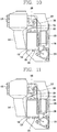
- FIGS. 9 to 11 are views schematically illustrating a heat pump and a sensing unit according to another embodiment of the present invention.
- FIG. 12 is a block diagram schematically illustrating a configuration for controlling a heating unit of the embodiment illustrated in FIGS. 9 to 11 .
- FIG. 13 is a flow chart illustrating a process for controlling a heating unit according to pressure by a control unit illustrated in FIG. 12 .
- the clothes treating apparatus having a heat pump according to another embodiment of the present invention will be described in detail with reference to FIGS. 1 through 13 .
- the clothes treating apparatus having a heat pump according to another embodiment of the present invention has a heat pump and a heating unit, and here, configurations of the heat pump and the heating unit are the same as those described above, so a detailed description thereof will be omitted.
- the sensing unit includes a pressure sensor 139 as a means for sensing pressure of a refrigerant.
- the pressure sensor 139 measures pressure of a refrigerant in a high pressure state.
- the pressure sensor 139 may be installed in the first connection pipe 191 supplying a refrigerant discharged from the compressor 150 to the condenser 130.
- the pressure sensor 139 may be installed on the first connection pipe 191 such that it is adjacent to the compressor 150 to measure pressure of the refrigerant discharged from the compressor 150.
- FIG. 9 the pressure sensor 139 may be installed in the first connection pipe 191 supplying a refrigerant discharged from the compressor 150 to the condenser 130.
- the pressure sensor 139 may be installed on the first connection pipe 191 such that it is adjacent to the compressor 150 to measure pressure of the refrigerant discharged from the compressor 150.
- the pressure sensor 139 may be installed in the refrigerant pipe 134 provided in the condenser 130 to measure pressure of the refrigerant in the condenser 130.
- the pressure sensor 139 may be installed in the second connection pipe 192 supplying the refrigerant discharged from the condenser 130 to the expander 160 to measure pressure of the refrigerant before being introduced to the expander 160.
- control unit 200' may be electrically connected to the foregoing pressure sensor 139 and the heater 170, respectively, to control power of the heater 170 on the basis of the pressure of the refrigerant sensed by the pressure sensor 139.
- a method for controlling power of the heater 170 as a heating unit on the basis of pressure of a refrigerant by the control unit 200' will be described with reference to FIG. 12 .
- the pressure sensor 139 senses pressure of a refrigerant.
- the sensed pressure of the refrigerant is measured when the refrigerant is in a high pressure state in the heat pump, and is sensed at one of the first connection pipe 191, the refrigerant pipe 134, and the second connection pipe 192.
- Pressure of the refrigerant is measured when the compressor 150 operates, and subsequently input as Pd to the control unit 200'.
- a unit of pressure is bar.
- a pressure comparison operation the control unit 200' determines whether the pressure Pd of the refrigerant is equal to or higher than a predetermined pressure value, e.g., 28 bar.
- a predetermined pressure value e.g., 28 bar.
- the process is returned to the pressure sensing operation (S410) and pressure of the refrigerant sensed by the pressure sensor 139 is input as Pd.
- the pressure Pd of the refrigerant is equal to or higher than 28 bar
- power of the heater 170 is cut off by the control unit 200' in a heating unit control operation (S430).
- the predetermined pressure value used as a reference for determining whether to cut off power of the heater 170 in other words, when to cut off power of the heater 170, may be changed according to a type of a refrigerant.
- FIG. 14 is a flow chart illustrating a method for controlling a clothes treating apparatus according to an embodiment of the present invention. The method for controlling a clothes treating apparatus having a heat pump according to an embodiment of the present invention will be described in detail with reference to FIGS. 1 to 9 and 14 .
- the clothes treating apparatus having a heat pump may perform a general drying process by actuating only a heat pump or may perform a speed drying process by actuating both the heat pump and the heater 170.
- FIG. 14 is a flow chart illustrating a method for controlling the heater 170 as a heating unit during the speed drying process.
- a method for controlling a clothes treating apparatus includes the power applying operation (S10), the temperature sensing operation (S21), and the heating unit control operation (S31), and power of the heater 170 is cut off by the control unit 200 as described above with reference to FIGs. 4 , 5 or 8 .
- FIG. 15 is a flow chart illustrating a method for controlling a clothes treating apparatus according to another embodiment of the present invention. The method for controlling a clothes treating apparatus having a heat pump according to another embodiment of the present invention will be described in detail with reference to FIG. 15 .
- the heat pump and the heater 170 may be simultaneously actuated in an early stage to perform speed drying, and since power of the heater 170 is cut off by determining a point in time at which the speed drying effect by the heater 170 is slowed on the basis of a physical parameter value of the refrigerant such as a refrigerant temperature (variation) or a refrigerant pressure (variation), energy efficiency in the remaining drying process can be increased and durability of the heat pump can be enhanced.
- a physical parameter value of the refrigerant such as a refrigerant temperature (variation) or a refrigerant pressure (variation)
Landscapes
- Engineering & Computer Science (AREA)
- Textile Engineering (AREA)
- Control Of Washing Machine And Dryer (AREA)
- Detail Structures Of Washing Machines And Dryers (AREA)
Description
- The present disclosure relates to a clothes treating apparatus having a heat pump and an operation method thereof, and more particularly, to a clothes treating apparatus having a heat pump and a heating unit and a control method thereof.
- In general, a clothes treating apparatus having dry performance like a washing machine or a dryer is an apparatus in which the laundry, in a state in which the laundry has been completely washed and spin-dried, is put into a drum and hot wind is supplied to the interior of the drum to evaporate moisture of the laundry to dry it.
- In case of a dryer, for example, a drum is rotatably installed within a body and receiving the laundry put thereto, a driving motor for driving the drum, a blower blowing air into the drum, and a heating unit for heating air introduced to the interior of the drum. The heating unit may use electrical resistance heat having a high temperature generated by using electrical resistance or may use combustion generated by burning gas.
- Meanwhile, air released from the drum contains moisture of the laundry within the drum, to become air of high temperature and humidity. Here, dryers may be classified into a condensing type dryer (or circulating dryer) and an exhaust-type dryer according to the way in which air of high temperature and humidity is treated. In the case of the condensing type dryer, air of high temperature and humidity is circulated, rather than being discharged to the outside, so as to be cooled to have a temperature lower than a dew-point temperature, thus condensing moisture included in the air of high temperature and humidity. In the case of the exhaust-type dryer, air of high temperature and humidity which has passed through the drum is directly discharged to the outside.
- In the case of the condensing type dryer, in order to condense air discharged from the drum, air is cooled to below a dew point, and before it is supplied again to the drum, air is required to be heated through the heating unit. In this case, as air is cooled during the condensing process, loss of thermal energy of air is caused, and in order to heat air to have a temperature sufficient for drying, an extra heater, and the like, is required.
- Also, in the case of the exhaust-type dryer, it is required to discharge air of high temperature and humidity to the outside, introduce ambient air having room temperature, and heat the introduced ambient air to reach a required temperature level through a heating unit. In particular, air of high temperature discharged to the outside contains thermal energy transmitted by the heating unit, but since it is discharged to the outside, heat efficiency is degraded.
- Thus, recently, a clothes treating apparatus capable of enhancing energy efficiency by recovering energy required for generating hot air and energy discharged to the outside, without being used has been presented. For example, a clothes treating apparatus having a heat pump has been introduced. The heat pump, having two heat exchangers, a compressor, and an expander, recovers energy of exhaust hot air and reuse it to heat air supplied to a drum, thus increasing energy efficiency.
- In detail, the heat pump transmits thermal energy of air of high temperature and humidity introduced from the drum through the evaporator to a refrigerant, and transmits thermal energy of the refrigerant to air flowing into the drum through the condenser, thereby generating hot air by using discarded energy. The use of heat pump enhances energy efficiency in comparison to the case in which drying is performed by using a heater.
-
US 2012/017466 A1 andUS 2012/017465 A1 each describe a heat pump type clothes dryer having an evaporator, a condenser, and a compressor. A temperature or pressure sensor is located in the center of the condenser and is coupled to a controller, which controls an auxiliary heater. -
WO 2012/134148 A2 describes a dryer having a heat pump system including a first heat exchanger for absorbing waste heat from air discharged out of a drum, a compressor, and a second heat exchanger for heating air introduced into the drum. A temperature sensor is installed at an inlet side of the first heat exchanger, and a temperature sensor is installed at an outlet side thereof. A further temperature sensor is disposed at the outlet side of the compressor. This dryer comprises further a heater as an auxiliary heat source which can be selectively turned on or off. When a temperature variation of the refrigerant at the outlet side of the compressor after driving the heater is smaller than a pre-set reference temperature variation, the control unit of the dryer turns the heater off. -
DE 43 04 226 A1 describes a dryer having a heat pump including an evaporator, a condenser and a refrigerant pipe. A temperature sensor monitors a temperature of a refrigerant flowing in the refrigerant pipe. -
DE 10 2007 016076 A1 describes a laundry dryer having a heat pump including an evaporator, a compressor, and a condenser. The dryer has a temperature sensor for measuring a temperature of a refrigerant. - In this manner, when the heat pump and the heating unit are provided together, hot air may be generated by using both the heat pump and the heating unit. In particular, when both the heat pump and the heating unit are used, air can be quickly heated, in comparison to a case in which only the heat pump is actuated, shortening a drying time but increasing energy consumption to degrade energy efficiency. Also, when the heating unit is operated together with the heat pump during a drying process, a time for a refrigerant to reach evaporation pressure in an evaporator of the heat pump is shortened, increasing pressure of a compressor driving unit of the heat pump.
- Therefore, an aspect of the invention is to provide a clothes treating apparatus and a method for controlling a clothes treating apparatus capable of increasing energy efficiency when a heat pump and a heating unit are operated together during a drying process and controlling power of the heating unit on the basis of at least one current physical parameter value of a heating medium, such as a refrigerant, circulating in the heat pump.
- Another aspect of the present invention is to provide a clothes treating apparatus and a method for controlling a clothes treating apparatus capable of preventing damage to a heat pump when the heat pump and a heating unit are operated together during a drying process and controlling power of the heating unit on the basis of at least one current physical parameter value of a heating medium circulating in the heat pump.
- To achieve these and other advantages and in accordance with the purpose of this specification, as embodied and broadly described herein, a clothes treating apparatus and a method for controlling a clothes treating apparatus according to the independent claims are provided.
- The clothes treating apparatus includes: a drum for accommodating a dry target; a heat pump configured to cool air transmitted from the drum and subsequently heat the same; a heating unit configured to heat air transmitted from the heat pump to the drum; a sensing unit configured to sense at least one physical parameter value of a heating medium in the heat pump; and a control unit configured to control the heating unit on the basis of the physical parameter value of the heating medium.
- Here, the heat pump includes a heating medium that circulates; a compressor configured to compress the heating medium; a condenser configured to heat air transmitted to the drum; an expander configured to expand the heating medium; and an evaporator configured to cool air transmitted from the drum.
- The control of power of the heating unit may include switching off the heating unit, so that only the heat pump is operated. Preferably, the heating unit is switched off under a condition of the heating medium indicating that a stable state of heating has been reached. Thus, the object of fast heating has been achieved and a heating using only the heat pump may be sufficient. By switching now off the heating unit, energy consumption can be decreased.
- Preferably, when a variation in the physical parameter value (e.g. temperature, pressure) is reduced compared with an initial variation in the physical parameter value of the heating medium by more than a predetermined numerical value, the control unit is configured to cut off power of the heating unit. That is, if (initial variation) - (current variation) > a, the heater is switched off. Similarly, when a difference between a currently sensed physical parameter value (variation) and a previously sensed physical parameter value (variation) of the heating medium is less than a predetermined numerical value a, the control unit may be configured to cut off power of the heating unit. That is, if (current value) - (previous value) < b, and/or (previous variation) - (current variation) < c, the heater is switched off.
- The control unit may be configured to operate the heating unit and the heat pump simultaneously or only one thereof. During hot air supply to the drum, the heating unit is preferably switched off, if a desired drum temperature is reached. Thus, the control unit may be configured to power off the heating unit, if the drum temperature is equal to or higher than a predetermined value.
- The sensing unit includes at least one temperature sensing unit and may include at least one pressure sensing unit for sensing the temperature, and preferably pressure, of the heating medium in the heat pump. The control unit controls the heating unit based on a temperature of the heating medium, and preferably on a pressure, of the heating medium.
- A temperature sensing unit may be arranged in a first connection pipe in which the heating medium flows from the compressor to the condenser. Here, the temperature sensing unit may be installed to be adjacent to the compressor to sense a temperature of the heating medium discharged from the compressor.
- The condenser may include a condenser heating medium pipe in which the heating medium flows. A temperature sensing unit may be arranged in the condenser heating medium pipe. Preferably, the temperature sensing unit is provided in the halfway point of the condenser heating medium pipe, i.e. in a middle portion along the condensor heating medium pipe. Therefore a temperature of the heating medium appropriately heat-exchanged in the condenser may be sensed.
- When a temperature of the heating medium is equal to or higher than a predetermined numerical value, the control unit may cut off power of the heating unit. By these means, damage of the heat pump may be prevented.
- Also, the temperature of the heating medium may be used as a measure for the drum temperature. Thus, when a current temperature of the heating medium is equal to or higher than a predetermined numerical value, the control unit may cut off power of the heating unit. Alternatively or additionally, when a temperature variation or increase of the heating medium for a predetermined period of time is reduced from an initial temperature variation or increase of the heating medium by more than a predetermined numerical value, the control unit may cut off power of the heating unit. Generally, the term temperature variation may refer to a temperature average between two points in time, i.e. the difference of the temperatures sensed at these two time points divided by the time interval there between, or a gradient, i.e. slope, of the temperature curve (temperature vs. time). Likewise, if the slope of the temperature curve (temperature vs. time) at a certain time point flattens below a predetermined value or if a difference between the current slope (variation) and the previous slope (variation) is less than a predetermined value, the heating unit may be switched off. In this situation, the heating operation has reached a stable state, in which the temperature of the heating medium remains nearly constant. Therefore, the additional heating by the heating unit used for increased heating rate is not necessary any longer. By these means, the heat efficiency of the laundry treatment apparatus can be optimized.
- In the embodiment with the sensing unit including a pressure sensing unit, a pressure sensing unit may be arranged in at least one of a first connection pipe in which the heating medium flows from the compressor to the condenser, a condenser heating medium pipe in which the heating medium flows in the condenser, and a second connection pipe in which the heating medium flows from the condenser to the expander.
- When pressure of the heating medium is equal to or greater than a predetermined numeral value, the control unit may cut off power of the heating unit.. By these means, damage of the heat pump may be prevented.
- Also, the pressure of the heating medium may be used as a measure for the drum temperature. Thus, when a current pressure of the heating medium is equal to or higher than a predetermined numerical value, the control unit may cut off power of the heating unit. Alternatively or additionally, when a pressure variation or increase of the heating medium for a predetermined period of time is reduced from an initial pressure variation or increase of the heating medium by more than a predetermined numerical value, the control unit may cut off power of the heating unit. Likewise, if the slope of the temperature curve (temperature vs. time) flattens below a predetermined value or if a difference between the current slope and a previous slope is less than a predetermined value, the heating unit may be switched off. In this situation, the heating operation has reached a stable state, in which the pressure of the heating medium remains nearly constant. Therefore, the additional heating by the heating unit used for increased heating rate is not necessary any longer. By these means, the heat efficiency of the laundry treatment apparatus can be optimized.
- The initial temperature variation and/or previous pressure variation may refer to a respective initial variation measured after powering up the heat pump, e.g. after a predetermined time t1. This value may be stored in a memory. Alternatively or additionally, the previous temperature variation and/or previous pressure variation may refer to the respective value measured before a current temperature variation and/or current pressure variation. Thus, the temperature variation and/or pressure variation may be determined repeatedly, and a difference between two subsequent temperature variations and/or pressure variations may be used for comparison with a predetermined value. If this difference is lower than the predetermined value, the heating unit may be switched off.
- To achieve these and other advantages and in accordance with the purpose of this specification, as embodied and broadly described herein, a method for controlling a clothes treating apparatus having a heat pump and a heating unit, includes: a hot air supplying operation of supplying hot air to a drum by applying power to a heat pump and a heating unit; a sensing operation of sensing at least one physical parameter value of a heating medium that circulates in the heat pump; and a heating unit control operation of controlling power of the heating unit on the basis of the physical parameter value of the heating medium. The method may be used by a control unit in a clothes treating apparatus according to any one of the above described embodiments. Preferably, during at least a part of the hot air supplying operation, the heat pump and the heating unit are operated simultaneously.
- The physical parameter value of a heating medium comprises a temperature, and preferably further a pressure, of the heating medium.
- In the heating unit control operation, when a temperature and/or a pressure of the heating medium is equal to or greater than a respective predetermined numerical value, heating unit may be switched off. Alternatively or additionally, in the heating unit control operation, when a temperature variation and/or a pressure variation of the heating medium is reduced from a previous temperature variation and/or pressure variation of the heating medium by more than a predetermined numerical value, power of the heating unit may be cut off.
- Here, a temperature of the heating medium comprises at least a temperature of the heating medium discharged from a compressor of the heat pump and may comprise a temperature of the heating medium that flows within a condenser of the heat pump.
- Likewise, a pressure of the heating medium may comprise at least one of a pressure of the heating medium that flows from the compressor of the heat pump to the condenser of the heat pump, a pressure of the heating medium that flows within the condenser, and a pressure of the heating medium that flows from the condenser of the heat pump to an expander of the heat pump
According to an embodiment of the present invention, the laundry can be quickly dried by actuating both the heat pump and the heating unit simultaneously and/or alternately, and since the heating unit is controlled on the basis of a value of one or more physical parameters and/or on the basis of a change of one or more physical parameters, i.e. in material properties of a heating medium, energy efficiency can be enhanced. - Also, according to an embodiment of the present invention, since the heating medium is prevented from being overheated by controlling the heating unit according to the physical properties of the heating medium and/or a change thereof, durability of the heat pump can be enhanced.
- In addition, according to an embodiment of the present invention, since a point in time at which power of the heating unit is to be controlled may be determined based on pressure and/or temperature of the heating medium, an ON/OFF operation of the heating unit can be precisely controlled.
- Further scope of applicability of the present application will become more apparent from the detailed description given hereinafter. However, it should be understood that the detailed description and specific examples, while indicating preferred embodiments of the invention, are given by way of illustration only, since various changes and modifications will become apparent to those skilled in the art from the detailed description.
- The accompanying drawings, which are included to provide a further understanding of the invention and are incorporated in and constitute a part of this specification, illustrate exemplary embodiments and together with the description serve to explain the principles of the invention.
- In the drawings:
-
FIG. 1 is a perspective view schematically illustrating an internal structure of a clothes treating apparatus according to an embodiment of the present invention; -
FIG. 2 is a view schematically illustrating a configuration of a heat pump and a sensing unit of the clothes treating apparatus illustrated inFIG. 1 ; -
FIG. 3 is a block diagram schematically illustrating a configuration for controlling a heating unit of the clothes treating apparatus illustrated inFIG. 2 ; -
FIG. 4 is a flow diagram illustrating a process of controlling the heating unit according to a temperature by a control unit of the clothes treating apparatus illustrated inFIG. 3 . -
FIG. 5 is a flow chart illustrating a process of controlling the heating unit according to a temperature by the control unit illustrated inFIG. 3 according to another embodiment of the present invention; -
FIG. 6 is a view schematically illustrating a heat pump and a sensing unit according to another embodiment of the present invention; -
FIG. 7 is a view illustrating a configuration of temperature sensing unit installed in a condenser illustrated inFIG. 6 ; -
FIG. 8 is a flow chart illustrating a process of controlling the heating unit according to a temperature by a control unit illustrated inFIG. 6 ; -
FIG. 9 is a view schematically illustrating a heat pump and a sensing unit according to another embodiment of the present invention; -
FIG. 10 is a view schematically illustrating a heat pump and a sensing unit according to another embodiment of the present invention; -
FIG. 11 is a view schematically illustrating a heat pump and a sensing unit according to another embodiment of the present invention; -
FIG. 12 is a block diagram schematically illustrating a configuration for controlling a heating unit of the embodiment illustrated inFIGS. 9 to 11 ; -
FIG. 13 is a flow chart illustrating a process for controlling a heating unit according to pressure by a control unit illustrated inFIG. 12 . -
FIG. 14 is a flow chart illustrating a method for controlling a clothes treating apparatus according to an embodiment of the present invention; and -
FIG. 15 is a flow chart illustrating a method for controlling a clothes treating apparatus according to another embodiment of the present invention. - Hereinafter, embodiments will be described in detail with reference to the accompanying drawings such that they can be easily practiced by those skilled in the art to which the present invention pertains. In describing the present invention, if a detailed explanation for a related known function or construction is considered to unnecessarily divert the gist of the present invention, such explanation will be omitted but would be understood by those skilled in the art.
-
FIG. 1 is a perspective view schematically illustrating an internal structure of a clothes treating apparatus according to an embodiment of the present invention.FIG. 2 is a view schematically illustrating a configuration of a heat pump and a sensing unit of the clothes treating apparatus illustrated inFIG. 1 .FIG. 3 is a block diagram schematically illustrating a configuration for controlling a heating unit of the clothes treating apparatus illustrated inFIG. 2 .FIG. 4 is a flow diagram illustrating a process of controlling the heating unit according to a temperature by a control unit of the clothes treating apparatus illustrated inFIG. 3 . - The embodiment of the present invention illustrated in
FIGS. 1 through 4 is applied to a dryer, but the present invention is not limited only to a dryer and may also be applicable to a certain clothes treating apparatus for drying the laundry by supplying hot air into a drum, e.g., a washing machine having a dry function, and the like. - Hereinafter, a clothes treating apparatus according to an embodiment of the present invention will be described in detail with reference to
FIGS. 1 through 4 . The clothes treating apparatus according to an embodiment of the present invention includes abody 100 forming the exterior and adrum 110 rotatably installed within thebody 100. The drum is rotatably supported by a supporter (not shown) in front and rear sides. - The
body 100 includes a door for opening and closing one side of thedrum 110 to allow a drying target (or a drying object) to be put into thedrum 110. Also, thebody 100 may include a display unit displaying information such as a drying process mode, a drying progress degree, real-time energy efficiency, and the like, when a drying process is performed. - An
intake duct 120 forming part of a flow path for transmitting air to the interior of thedrum 110 is installed at a lower portion of thedrum 110. An end portion of theintake duct 120 is connected to an end portion of aback duct 122. Theback duct 122 extends in a vertical direction of thebody 100 between theintake duct 120 and thedrum 110 to supply air, which has passed through theintake duct 120, to the interior of thedrum 110. Thus, a flow path transmitting air to thedrum 110 is formed by theintake duct 120 and theback duct 122. - Air supplied through the flow path is introduced from the outside into the
body 100 through an intake port (not shown), e.g. formed in a rear surface or at a lower portion of thebody 100, and transferred to theintake duct 120. In order to induce an air movement, anintake fan 185 may be installed in an end portion of theintake duct 120. Namely, according to rotation of theintake fan 185, air staying within thebody 100 is introduced to theintake duct 120, and accordingly, pressure within thebody 100 is lowered to allow ambient air to be introduced into thebody 100 through the intake port. - Here, it is not necessary to introduce air within the
body 100, and an example in which air outside of thebody 100 is introduced may also be considered. - Meanwhile, a
condenser 130 is installed in front of the fan (i.e., in an upper stream side on the basis of an air flow path). Thecondenser 130, together with anevaporator 135, acompressor 150, and anexpander 160 as described hereinafter, constitutes a heat pump. Also, the heat pump includes a heating medium circulating within the heat pump. The heating medium is compressed by thecompressor 150 and subsequently supplied to thecondenser 130 through afirst connection pipe 191 connecting thecompressor 150 and thecondenser 130. The heating medium emits heat in thecondenser 130 and is subsequently supplied to theexpander 160 through asecond connection pipe 192 connecting thecondenser 130 and theexpander 160. The heating medium expanded by theexpander 160 is supplied to anevaporator 135 through athird connection pipe 193 connecting theexpander 160 and theevaporator 135. The heating medium absorbs heat in theevaporator 135 and is subsequently supplied to thecompressor 150 through afourth connection pipe 194 connecting theevaporator 135 and thecompressor 150. In this manner, the heating medium circulates in the heat pump. In the present disclosure, a heating medium acts as a refrigerant in theevaporator 135, so a heating medium will be referred to as a refrigerant. - In the
condenser 130, asingle refrigerant pipe 134 as a condenser heating medium pipe is disposed in a winding or meandering manner, and a plurality ofheat dissipation fins 132 are installed perpendicular to the plane of the air flow path in therefrigerant pipe 134. Namely, therefrigerant pipe 134 penetrates through theheat dissipation fins 132 disposed in piles (or in layers) at predetermined intervals therebetween. One end of therefrigerant pipe 134 is connected to the foregoingfirst connection pipe 191 to receive a compressed refrigerant from thecompressor 150, and the other end of therefrigerant pipe 134 is connected to thesecond connection pipe 192 to supply a refrigerant to theexpander 160. Meanwhile, since theintake fan 185 is positioned downstream of thecondenser 130 in the air flow path, air drawn in by the intake fan 184 is heat-exchanged with the refrigerant, while passing through theheat dissipation fins 132 of thecondenser 130, and thus, air having an increased temperature is introduced to the interior of thedrum 110. Here, a linear expansion valve whose opening degree is controlled by an electrical signal may be used as theexpander 160. - A heating unit including a
heater 170 is installed within theback duct 122 in order to additionally heated air in a case in which air is not sufficiently or quickly heated using only thecondenser 130. Of course, theheater 170 may also be installed in theintake duct 120. Air heated while passing through thecondenser 130 and theheater 170 is introduced as hot air having a high temperature to the interior of thedrum 110 and subsequently dry a drying target accommodated within thedrum 110. - Thereafter, the hot air is transmitted to an
exhaust duct 140 by anexhaust fan 180, heat-exchanged with a refrigerant having a low temperature passing through the interior of theevaporator 135 disposed in an end portion of theexhaust duct 140, and subsequently discharged to the outside of thebody 100. Through the heat-exchanging process, the air is discharged to the outside in a state in which it has a lower temperature and humidity. At this time, a portion of thermal energy of the air discharged from thedrum 110, passing through theevaporator 135, is transmitted to the refrigerant, and the thermal energy is used to heat air again in thecondenser 130. Thus, since thermal energy, which is discarded in the related art, is collected and recycled to generate hot air, energy consumption can be reduced. Also, in a case in which quick drying is required, theheater 170, as an additional heating unit, may be operated, whereby drying can be performed flexibly. - Here, when the
heater 170 is operated together with the heat pump, energy efficiency is degraded, in comparison to the case in which drying is performed by actuating only the heat pump. Also, when theheater 170 is continuously turned on during the drying operation, a time for the refrigerator to reach evaporation pressure in theevaporator 135 is reduced, which may lay a burden on a driving unit of thecompressor 150. Thus, in the present embodiment, a sensing unit for sensing a current value of at least one physical parameter of a refrigerant used as a heating medium circulating in the heat pump and a control unit for controlling power of theheater 170 on the basis of the current value of the physical parameter of the refrigerant are further provided. The current physical parameter values of a refrigerant refer to qualities based on which a physical state such as a temperature or pressure of the refrigerant can be determined. - In detail, in an embodiment of the present invention, the sensing unit includes a unit for sensing a temperature of a refrigerant, which includes a
temperature sensor 137. Thetemperature sensor 137 may measure a temperature of the refrigerant discharged from thecompressor 150. Thetemperature sensor 137 may be attached to thefirst connection pipe 191, such that it is adjacent to thecompressor 150. A temperature of the refrigerant discharged from thecompressor 150 can be inferred by measuring a temperature of a surface of thefirst connection pipe 191 adjacent to thecompressor 150, so thetemperature sensor 137 is simply attached to the surface of thefirst connection pipe 191 to sense a temperature of the refrigerant. - The
control unit 200 may be electrically connected to thetemperature sensor 137 and theheater 170, respectively, as described above, to control power of theheater 170 on the basis of the sensed temperature of the refrigerant. In detail, a method for controlling power of theheater 170 as a heating unit on the basis of a temperature of a refrigerant by thecontrol unit 200 will be described with reference toFIG. 4 . - First, in a temperature sensing operation S110, a temperature of the refrigerant is sensed by the
temperature sensor 137. The sensed temperature of the refrigerant may be a temperature of the refrigerant when it is discharged from thecompressor 150. The measurements of the temperature of the refrigerant may be started at a time when thecompressor 150 is operated first, and subsequently input as a TC0 to thecontrol unit 200. In a temperature comparison operation (S120), thecontrol unit 200 determines whether the current temperature TC0 of the refrigerant discharged from the compressor is equal to or higher than a predetermined temperature value, e.g., 90°C. When the TC0 is lower than 90°C, the process is returned to the temperature sensing operation (S110) and a temperature of the refrigerant discharged from the compressor sensed by thetemperature sensor 137 is continuously input as a TC0. Meanwhile, when the temperature of the refrigerant discharged from the compressor is equal to or higher than 90°C, power of theheater 170 is cut off by thecontrol unit 200 in a heating unit control operation (S130). However, a reference temperature value as a comparison target in the temperature comparison operation (S120) may be changed, e.g. according to a type of a refrigerant. Namely, the temperature of the refrigerant discharged from the compressor, at which power of theheater 170 is to be cut off, may be changed according to a type of a refrigerant. - With the foregoing configuration, the
temperature sensor 137 is simply attached to the surface of thefirst connection pipe 191, simplifying assembly. Also, when the refrigerant is discharged from thecompressor 150, it has the highest energy state. Thus, power of theheater 170 may be cut off based on a temperature of the refrigerant when the energy thereof has the highest level, whereby theheater 170 is effectively prevented from being actuated more than necessary, and through this method, overall energy efficiency can be enhanced. - However, the
temperature sensor 137 may be attached to a middle portion of thefirst connection pipe 191 or to a portion of thefirst connection pipe 191 adjacent to thecondenser 130, as necessary, such as for the reason of design, space or the like. Also, a temperature value of the refrigerant as a reference for cutting off power of theheater 170 by thecontrol unit 200 may be changed according to a type of the refrigerant, a position in which thetemperature sensor 137 is attached, a revolution per minute (RPM) of thecompressor 150, and the like. -
FIG. 5 is a flow chart illustrating a process of controlling the heating unit according to a temperature by the control unit illustrated inFIG. 3 according to another embodiment of the present invention. A method for controlling the heating unit according to a temperature by the control unit according to another embodiment of the present invention will be described in detail. - The
control unit 200 according to another embodiment of the present invention may be electrically connected to thetemperature sensor 137 and theheater 170, respectively. Thecontrol unit 200 controls power of theheater 170 as a heating unit by calculating a difference between temperature variations or pressure variations of the refrigerant sensed respectively by atemperature sensor 137 or apressure sensor 139. In detail, a method for controlling power of theheater 170 as a heating unit by thecontrol unit 200 on the basis of a difference between temperatures or on the basis of a difference between pressures of the refrigerant is provided. One embodiment for this method using temperature differences will be described in detail with reference toFIG. 5 . However, it is pointed out that instead of temperature differences, also pressure differences can be used in this embodiment. - First, in sensing operations (S210 to S240), a temperature of the refrigerant is sensed several times at different time points by the
temperature sensor 137, e.g. as illustrated inFIG. 2 . Here, thetemperature sensor 137 senses temperatures of the refrigerant discharged from thecompressor 150 . Of course, also other positions of thetemperature sensor 137 are possible, e.g. as shown inFigs. 6 and 7 (described below). - In detail, in the first sensing operation (S210), a temperature of the refrigerant at a first point in time is sensed by the
temperature sensor 137. The first point in time may refer to a time when t1 seconds, e.g., 30 seconds has elapsed since thecompressor 150 was operated. - In the second sensing operation (S220), a temperature of the refrigerant at a second point in time is sensed by the
temperature sensor 137. The second point in time refers to a time when t2 seconds (e.g., 130 seconds) has lapsed since thecompressor 150 was operated. Here, the second point in time may be a point in time when a predetermined time (Δt) has lapsed after the first point. Specifically, t2 seconds may be defined as the sum of t1 seconds and the predetermined time (Δt). - In the third sensing operation (S230), a temperature of the refrigerant at a third point in time is sensed by the
temperature sensor 137. The third point in time may be a point in time when t3 seconds has lapsed after thecompressor 150 was operated. - In the fourth sensing operation (S240), a temperature of the refrigerant at a fourth point in time may be sensed. The fourth point in time may be defined as a point in time when t4 seconds has lapsed after the
compressor 150 was operated. Here, the fourth point in time may be defined as any point in time after the t2 seconds. Also, the third point in time may be defined to be a point in time by the predetermined time (Δt) ahead of the fourth point in time. Thus, when t1 seconds is e.g. 30 seconds and Δt is e.g. 100 seconds, t2 seconds is 130 seconds. And t3 seconds may be any point in time after 130 seconds, and t4 seconds is Δt after t3 seconds, e.g. 100 seconds later than t3. - The control unit may input the temperature of the refrigerant when t1 seconds have lapsed after the
compressor 150 was operated, as TC1, and inputs the temperature of the refrigerant when t2 seconds have lapsed after thecompressor 150 was operated, as TC2. Also, thecontrol unit 200 may input the temperature of the refrigerant when t3 seconds have lapsed after thecompressor 150 was operated, as TC3, and inputs the temperature of the refrigerant when t4 seconds have lapsed after thecompressor 150 was operated, as TC4. - However, in the sensing operation (S210 to S240), the
temperature sensor 137 may also continuously sense the temperature of the refrigerant discharged from the compressor, starting from when thecompressor 150 is operated, and thecontrol unit 200 may input the temperatures of the refrigerant corresponding to a first to nth points in time, as TC1 to TCn (n being an integer >=4). - In the comparison operation (S250), the
control unit 200 may calculate a temperature variation during the predetermined time Δt on the basis of the previously input TC1 to TC4 as expressed byEquation 1 below, and compare the same with a predetermined value. After receiving TC1 and TC2, the control unit may determine an initial temperature variation, i.e. by calculating the slope (TC2-TC1)/(t2-t1). The value of the initial temperature variation may be stored in order to be used for comparison with a current temperature variation. Namely, thecontrol unit 200 may calculate the initial temperature variation for Δt (100 seconds) from the first point in time to the second point in time and an average temperature variation for Δt (100 seconds) from the third point in time to the fourth point in time are calculated, respectively. Thereafter, a difference value between the temperature variation from the first point in time to the second point in time and the temperature variation from the third point in time to the fourth point in time. Thereafter, thecontrol unit 200 determines whether the difference value between the temperature variations is equal to or greater than a predetermined value, e.g. 0.05°C/sec.
- In step S250, the value calculated by
Equation 1 is compared with a predetermined value. When the value calculated byEquation 1 is less than the predetermined value, e.g., 0.05°C/sec, thecontrol unit 200 returns to the third sensing operation (S230). Here, thecontrol unit 200 inputs a refrigerant temperature at a point intime 100 seconds (Δt) earlier from a current point in time, as TC3. In the fourth sensing operation (S240), thetemperature sensor 137 senses a temperature of the refrigerant discharged from the compressor at the current point in time, and thecontrol unit 200 inputs the temperature of the refrigerant at the current point in time, as TC4, and repeatedly performs the comparison operation (S250) again based on the initial temperature variation stored in the memory. In the comparison operation (S250), when the value calculated byEquation 1 is equal to or greater than e.g. 0.05°C/sec, power of theheater 170 is cut off in the heating unit control operation (S260). Instead of the initial temperature (pressure) variation, a value of the previous temperature (pressure) variation that was measured prior to the current temperature (pressure) variation may be used in the comparison operation (S250). In this case, alsoEquation 1 may be used, with TC2-TC1 referring to the previous temperature variation measured prior to the current temperature variation. If the comparison result ofEquation 1 is less than a predetermined value, the heater is controlled to be switched off in the heating unit control operation (S260). - However, a predetermined value as a reference for determining whether to cut off power of the
heater 170 by thecontrol unit 200 may be changed according to a type of a refrigerant, and the like. - According to the foregoing configuration, on the basis of the temperature variation of the refrigerant for the predetermined time (Δt), when a current temperature variation (i.e., the temperature variation from the third point of time to the fourth point in time) is significantly reduced in comparison to the previous temperature variation (i.e., the temperature variation from the first point in time to the second point in time), it means that a temperature increase rate of air heated by the
heater 170 is lowered in comparison to the previous time, and at this time, power of theheater 170 is cut off, enhancing energy efficiency. Also, although a temperature or pressure of the refrigerant may be changed according to the RPM of thecompressor 150, a temperature or pressure variation of the refrigerant is not affected by the RPM of thecompressor 150. Thus, a point in time at which power of theheater 170 is to be cut off can be more accurately determined. -
FIG. 6 is a view schematically illustrating a heat pump and a sensing unit according to another embodiment of the present invention.FIG. 7 is a view illustrating a configuration of temperature sensing unit installed in a condenser illustrated inFIG. 6 .FIG. 8 is a flow chart illustrating a process of controlling the heating unit according to a temperature by a control unit illustrated inFIG. 6 . The clothes treating apparatus having a heat pump according to another embodiment of the present invention will be described in detail with reference toFIGS. 1 through 8 . - The clothes treating apparatus having a heat pump according to another embodiment of the present invention has a heat pump and a heating unit, and here, configurations of the heat pump and the heating unit are the same as those described above, so a detailed description thereof will be omitted.
- The sensing unit includes the
temperature sensor 137 as a means for sensing a temperature of a refrigerant. Thetemperature sensor 137 measures a temperature of a refrigerant flowing in therefrigerant pipe 134 of thecondenser 130. As illustrated inFIGS. 6 and 7 , thetemperature sensor 137 is attached to a portion bent to have a U-like shape formed in the halfway point of therefrigerant pipe 134. Here,FIG. 6 is a plan view illustrating the heat pump of the clothes treating apparatus viewed from the top according to another embodiment of the present invention, andFIG. 7 is a side view illustrating a cross-sectional arrangement of therefrigerant pipe 134 when thecondenser 130 illustrated inFIG. 6 is viewed from the side. A temperature of a refrigerant may be inferred by measuring a surface temperature of the refrigerant pipe 1334, so a temperature of a refrigerant is sensed by simply attaching thetemperature sensor 137 to the surface of therefrigerant pipe 134. - According to the foregoing configuration, since the
temperature sensor 137 is preferably attached to a portion positioned outside of stacked heat dissipation pins 132, rather than to a portion positioned between the heat dissipation pins 132 of therefrigerant pipe 134, it can accurately sense a temperature of the refrigerant without being affected by air heat-changed while flowing between theheat dissipation fins 132. - As illustrated in
FIG. 3 , thecontrol unit 200 may be electrically connected to thetemperature sensor 137 and theheater 170, respectively, to control power of theheater 170 on the basis of a temperature of the refrigerant sensed by thetemperature sensor 137. In detail, a method for controlling power of theheater 170 as a heating unit on the basis of a temperature of a refrigerant by thecontrol unit 200 will be described with reference toFIG. 8 . - First, in a temperature sensing operation (S310), the
temperature sensor 137 senses a temperature of a refrigerant in thecondenser 130 when thecompressor 150 is actuated. The sensed temperature TCC of the refrigerant is a temperature of the refrigerant flowing in therefrigerant pipe 134 of thecondenser 130, and in this case, since thetemperature sensor 137 is attached to a middle portion of therefrigerant pipe 134, a temperature of the refrigerant heat-exchanged with air drawn in to the drum to a degree is sensed. The temperature of the refrigerant in thecondenser 130 is input as a TCC to thecontrol unit 200. - In a temperature comparison operation (S320), the
control unit 200 determines whether the temperature (TCC) of the refrigerant of thecondenser 130 is equal to or higher than a predetermined temperature value, e.g., 80°C. When the temperature TCC is lower than 80°C, the process is returned to the temperature sensing operation (S310) and a temperature of the refrigerant is continuously sensed by thetemperature sensor 137. The sensed temperature of the refrigerant is input as TCC to thecontrol unit 200. When the temperature TCC of the refrigerant is equal to or higher than 80°C, power of theheater 170 as a heating unit is cut off by thecontrol unit 200 in a heating unit control operation (S330). However, the temperature of the refrigerant used as a reference temperature for determining whether to cut off power of theheater 170, may be changed according to a type of the refrigerant. - According to the foregoing configuration, since the
temperature sensor 137 is simply attached to the surface of therefrigerant pipe 134 protruded in a U-like shape in thecondenser 130, the assembly process can be simplified. Also, according to the foregoing configuration, since thetemperature sensor 137 is attached to a middle portion of therefrigerant pipe 134, a temperature of the refrigerant appropriately heat-exchanged in thecondenser 130 may be sensed, and when the temperature TCC of the refrigerant is equal to or higher than a predetermined temperature, there is no need to re-heat air with theheater 170 and the power of theheater 170 is cut off to thus prevent theheater 170 from being unnecessarily actuated, enhancing energy efficiency. - However, an attachment position of the
temperature sensor 137 to therefrigerant pipe 134 may be changed as necessary, for example, for the reason of a design, space or the like. Also, the temperature value used as a reference for determining whether to cut off power of theheater 170 by thecontrol unit 200 may be changed according to a type of the refrigerant, the attachment position of thetemperature sensor 137, and the like. -
FIGS. 9 to 11 are views schematically illustrating a heat pump and a sensing unit according to another embodiment of the present invention.FIG. 12 is a block diagram schematically illustrating a configuration for controlling a heating unit of the embodiment illustrated inFIGS. 9 to 11 .FIG. 13 is a flow chart illustrating a process for controlling a heating unit according to pressure by a control unit illustrated inFIG. 12 . The clothes treating apparatus having a heat pump according to another embodiment of the present invention will be described in detail with reference toFIGS. 1 through 13 . - The clothes treating apparatus having a heat pump according to another embodiment of the present invention has a heat pump and a heating unit, and here, configurations of the heat pump and the heating unit are the same as those described above, so a detailed description thereof will be omitted.
- The sensing unit includes a
pressure sensor 139 as a means for sensing pressure of a refrigerant. Here, thepressure sensor 139 measures pressure of a refrigerant in a high pressure state. For example, as illustrated inFIG. 9 , thepressure sensor 139 may be installed in thefirst connection pipe 191 supplying a refrigerant discharged from thecompressor 150 to thecondenser 130. In this case, thepressure sensor 139 may be installed on thefirst connection pipe 191 such that it is adjacent to thecompressor 150 to measure pressure of the refrigerant discharged from thecompressor 150. Alternatively or additionally, as illustrated inFIG. 10 , thepressure sensor 139 may be installed in therefrigerant pipe 134 provided in thecondenser 130 to measure pressure of the refrigerant in thecondenser 130. Alternatively or additionally, as illustrated inFIG. 11 , thepressure sensor 139 may be installed in thesecond connection pipe 192 supplying the refrigerant discharged from thecondenser 130 to theexpander 160 to measure pressure of the refrigerant before being introduced to theexpander 160. - As illustrated in
FIG. 12 , the control unit 200' may be electrically connected to the foregoingpressure sensor 139 and theheater 170, respectively, to control power of theheater 170 on the basis of the pressure of the refrigerant sensed by thepressure sensor 139. A method for controlling power of theheater 170 as a heating unit on the basis of pressure of a refrigerant by the control unit 200' will be described with reference toFIG. 12 . - First, in a pressure sensing operation (S410), the
pressure sensor 139 senses pressure of a refrigerant. The sensed pressure of the refrigerant is measured when the refrigerant is in a high pressure state in the heat pump, and is sensed at one of thefirst connection pipe 191, therefrigerant pipe 134, and thesecond connection pipe 192. Pressure of the refrigerant is measured when thecompressor 150 operates, and subsequently input as Pd to the control unit 200'. A unit of pressure is bar. - In a pressure comparison operation (S420), the control unit 200' determines whether the pressure Pd of the refrigerant is equal to or higher than a predetermined pressure value, e.g., 28 bar. When the pressure Pd of the refrigerant is lower than 28 bar, the process is returned to the pressure sensing operation (S410) and pressure of the refrigerant sensed by the
pressure sensor 139 is input as Pd. Meanwhile, when the pressure Pd of the refrigerant is equal to or higher than 28 bar, power of theheater 170 is cut off by the control unit 200' in a heating unit control operation (S430). However, the predetermined pressure value used as a reference for determining whether to cut off power of theheater 170, in other words, when to cut off power of theheater 170, may be changed according to a type of a refrigerant. - According to the foregoing configuration, since pressure of the refrigerant is directly measured, power of the
heater 170 is cut off before the pressure reaches to a level at which the driving unit of thecompressor 150, and the like, is overloaded, and thus, durability of thecompressor 150 can be enhanced and energy efficiency can be increased. -
FIG. 14 is a flow chart illustrating a method for controlling a clothes treating apparatus according to an embodiment of the present invention. The method for controlling a clothes treating apparatus having a heat pump according to an embodiment of the present invention will be described in detail with reference toFIGS. 1 to 9 and14 . - The clothes treating apparatus having a heat pump according to an embodiment of the present invention may perform a general drying process by actuating only a heat pump or may perform a speed drying process by actuating both the heat pump and the
heater 170.FIG. 14 is a flow chart illustrating a method for controlling theheater 170 as a heating unit during the speed drying process. - First, when the speed drying process is selected, power is applied to the heat pump in a power applying operation (S10) and power is applied to the
heater 170 as a heating unit. Next, in a temperature sensing operation (S21), a temperature of a refrigerant is sensed by thetemperature sensor 137. Thereafter, in a heating unit control operation (S31), power of theheater 170 is cut off according to the temperature of the refrigerant by thecontrol unit 200. A detailed control method has been described above with reference toFIGS. 4 and5 . - Also, a method for controlling a clothes treating apparatus according to another embodiment of the present invention includes the power applying operation (S10), the temperature sensing operation (S21), and the heating unit control operation (S31), and power of the
heater 170 is cut off by thecontrol unit 200 as described above with reference toFIGs. 4 ,5 or8 . -
FIG. 15 is a flow chart illustrating a method for controlling a clothes treating apparatus according to another embodiment of the present invention. The method for controlling a clothes treating apparatus having a heat pump according to another embodiment of the present invention will be described in detail with reference toFIG. 15 . - First, like the embodiment as described above, when the speed drying process is selected, power is applied to the heat pump and power is applied to the
heater 170 as a heating unit in the power applying operation (S10). Next, in a pressure sensing operation (S22), pressure of the refrigerant is sensed by thepressure sensor 139 as described above with reference toFIGS. 9 through 13 . Thereafter, in a heating unit control operation (S32), power of theheater 170 is cut off on the basis of pressure of the refrigerant by the control unit 200' as described above. A detailed control method has been described above with reference toFIG. 13 . Another control method has been described above with reference toFIG. 5 using temperature as physical parameter. However, as also mentioned above, the method ofFIG. 5 may also be applied using pressure as physical parameter. - According to the control method according to the foregoing embodiments, the heat pump and the
heater 170 may be simultaneously actuated in an early stage to perform speed drying, and since power of theheater 170 is cut off by determining a point in time at which the speed drying effect by theheater 170 is slowed on the basis of a physical parameter value of the refrigerant such as a refrigerant temperature (variation) or a refrigerant pressure (variation), energy efficiency in the remaining drying process can be increased and durability of the heat pump can be enhanced. - The foregoing embodiments and advantages are merely exemplary and are not to be considered as limiting the present disclosure. The present teachings can be readily applied to other types of apparatuses. This description is intended to be illustrative, and not to limit the scope of the claims. Many alternatives, modifications, and variations will be apparent to those skilled in the art. The features, structures, methods, and other characteristics of the exemplary embodiments described herein may be combined in various ways to obtain additional and/or alternative exemplary embodiments.
Claims (10)
- A clothes treating apparatus having a heat pump, the apparatus comprising:a drum (100) for accommodating a drying target;a heat pump configured to cool air transmitted from the drum (110), the heat pump including a heating medium that circulates, a compressor (150) configured to compress the heating medium, a condenser (130) configured to heat air transmitted to the drum (100), an expander (160) configured to expand the heating medium, and an evaporator (135) configured to cool air transmitted from the drum (160);a heating unit (170) configured to heat air transmitted from the heat pump to the drum (110);a sensing unit configured to sense at least one physical parameter value of the heating medium wherein the at least one physical parameter value of the heating medium includes a temperature of the heating medium, and wherein the sensing unit comprises a temperature sensing unit (137) configured to sense the temperature of the heating medium; anda control unit (200) configured to control the heating unit on the basis of the at least one physical parameter value of the heating medium,wherein the control unit (200) is configured to calculate a temperature variation of the heating medium discharged from the compressor (150), andwherein the control unit (200) is configured to cut off power of the heating unit when a difference between an initial temperature variation of the heating medium and a current temperature variation of the heating medium is equal to or greater than a predetermined value.
- The clothes treating apparatus of claim 1, wherein the at least one physical parameter value of the heating medium includes further a pressure of the heating medium.
- The clothes treating apparatus of claim 2, wherein when a pressure variation of the heating medium is reduced compared to an initial value of pressure variation of the heating medium by more than a predetermined numerical value, the control unit (200) is configured to cut off power of the heating unit (170).
- The clothes treating apparatus of any one of the preceding claims, wherein the sensing unit further comprises a pressure sensing unit configured to sense a pressure of the heating medium.
- The clothes treating apparatus of any one of the preceding claims, wherein the temperature sensing unit (137) is installed in at least one of a flow path of the heating medium between the compressor (150) of the heat pump and a condenser (130) of the heat pump and a flow path of the heating medium within the condenser (130).
- The clothes treating apparatus of claim 4, wherein the pressure sensing unit is installed in at least one of a flow path of the heating medium between the compressor (150) and the condenser (130), a flow path of the heating medium within the condenser (130), and a flow path of the heating medium between the condenser (130) and an expander (160) of the heat pump.
- A method for controlling a clothes treating apparatus having a heat pump and a heating unit (170), the heat pump comprising a heating medium that circulates, a compressor (150) configured to compress the heating medium, a condenser (130) configured to heat air transmitted to the drum (100), an expander (160) configured to expand the heating medium, and an evaporator (135) configured to cool air transmitted from the drum (160); the method comprising:a hot air supplying operation of supplying hot air to a drum (110) by applying power to the heat pump and the heating unit (170);a sensing operation (S210, S220, S230, S240) of sensing at least one physical parameter value of a heating medium that circulates in the heat pump, wherein the at least one physical parameter value of the heating medium includes a temperature of the heating medium; anda heating unit control operation (250) of controlling power of the heating unit (170) on the basis of the at least one physical parameter value of the heating medium,wherein a temperature variation of the heating medium discharged from a compressor (150) of the heat pump is calculated and the power of the heating unit (170) is cut off when a difference between an initial temperature variation of the heating medium and a current temperature variation of the heating medium is equal to or greater than a predetermined value.
- The method of claim 7, wherein the at least one physical parameter value of the heating medium comprises further a pressure of the heating medium.
- The method of claim 8, wherein the temperature of the heating medium comprises the temperature of the heating medium discharged from a compressor of the heat pump and a temperature of the heating medium that flows within a condenser of the heat pump.
- The method of claim 8, wherein a pressure of the heating medium comprises at least one of pressure of the heating medium that flows from the compressor (150) of the heat pump to a condenser (130) of the heat pump, pressure of the heating medium that flows within the condenser (130), and pressure of the heating medium that flows from the condenser (130) to an expander (160) of the heat pump.
Applications Claiming Priority (1)
| Application Number | Priority Date | Filing Date | Title |
|---|---|---|---|
| KR1020120117474A KR102009277B1 (en) | 2012-10-22 | 2012-10-22 | Clothes treating apparatus with a heat pump and operating method thereof |
Publications (3)
| Publication Number | Publication Date |
|---|---|
| EP2722432A2 EP2722432A2 (en) | 2014-04-23 |
| EP2722432A3 EP2722432A3 (en) | 2015-04-22 |
| EP2722432B1 true EP2722432B1 (en) | 2019-04-24 |
Family
ID=49378170
Family Applications (1)
| Application Number | Title | Priority Date | Filing Date |
|---|---|---|---|
| EP13189197.0A Not-in-force EP2722432B1 (en) | 2012-10-22 | 2013-10-18 | Clothes treating apparatus with heat pump and control method thereof |
Country Status (8)
| Country | Link |
|---|---|
| US (1) | US20140109436A1 (en) |
| EP (1) | EP2722432B1 (en) |
| KR (1) | KR102009277B1 (en) |
| CN (1) | CN103774397B (en) |
| AU (2) | AU2013245554A1 (en) |
| BR (1) | BR102013026924B1 (en) |
| DE (1) | DE202013104697U1 (en) |
| RU (1) | RU2560343C2 (en) |
Families Citing this family (6)
| Publication number | Priority date | Publication date | Assignee | Title |
|---|---|---|---|---|
| KR101467494B1 (en) * | 2014-07-21 | 2014-12-01 | 박상래 | Drying unit for an drying apparatus of laundry using heat-pump system |
| WO2017005528A1 (en) | 2015-07-08 | 2017-01-12 | Arcelik Anonim Sirketi | A heat pump laundry dryer comprising a heater |
| KR102408516B1 (en) * | 2017-11-20 | 2022-06-13 | 엘지전자 주식회사 | Control method of the clothes drier |
| US10900164B2 (en) | 2018-02-23 | 2021-01-26 | Samsung Electronics Co., Ltd. | Clothes dryer and control method thereof |
| KR20200037041A (en) * | 2018-09-29 | 2020-04-08 | 엘지전자 주식회사 | Pet bathing apparatus |
| CN112824578B (en) * | 2019-11-21 | 2024-02-06 | 重庆海尔滚筒洗衣机有限公司 | Control method of clothes treatment equipment and clothes treatment equipment |
Citations (1)
| Publication number | Priority date | Publication date | Assignee | Title |
|---|---|---|---|---|
| WO2012044038A2 (en) * | 2010-09-30 | 2012-04-05 | Lg Electronics Inc. | Diagnosing method for clothes treating apparatus and clothes treating apparatus with refrigerant leakage detecting means |
Family Cites Families (20)
| Publication number | Priority date | Publication date | Assignee | Title |
|---|---|---|---|---|
| JPS616588A (en) * | 1984-06-20 | 1986-01-13 | Hitachi Ltd | Finned tube type heat exchanger |
| JPH0686969B2 (en) * | 1984-12-07 | 1994-11-02 | 株式会社日立製作所 | Air-cooled heat pump type refrigeration cycle |
| DE4304226C5 (en) * | 1993-02-12 | 2004-03-04 | Miele & Cie. Kg | Condensation clothes dryer with a heat pump |
| KR100955484B1 (en) * | 2003-04-30 | 2010-04-30 | 삼성전자주식회사 | Washing Machine And For Drying Control Method |
| KR100606720B1 (en) * | 2004-06-14 | 2006-08-01 | 엘지전자 주식회사 | Drying Machine and Method for Controlling Drying Process of the Same |
| CN1828153A (en) * | 2005-12-21 | 2006-09-06 | 广东科龙电器股份有限公司 | Self-adaptive type super low temperature refrigeration air conditioner |
| CN201028907Y (en) * | 2006-08-14 | 2008-02-27 | 宋学 | Multipurpose cooling and warming recirculation water portable device |
| EP1959043B1 (en) * | 2007-02-19 | 2018-11-14 | Electrolux Home Products Corporation N.V. | Domestic appliance with external water supply |
| JP2008237496A (en) * | 2007-03-27 | 2008-10-09 | Toshiba Corp | Clothes drying machine |
| DE102007016076A1 (en) * | 2007-04-03 | 2008-10-09 | BSH Bosch und Siemens Hausgeräte GmbH | Article e.g. laundry, drying method for use with e.g. laundry dryer, involves measuring thermal load of heat pump circuit, and terminating heating when thermal load achieves predetermined threshold value |
| EA017367B1 (en) * | 2007-12-11 | 2012-11-30 | Бсх Бош Унд Сименс Хаусгерете Гмбх | Household appliance comprising a first air conduit and a heat pump |
| DE102008014853B4 (en) * | 2008-03-18 | 2010-11-18 | Ascending Technologies Gmbh | Rotary-wing aircraft |
| DE102008040946A1 (en) * | 2008-08-01 | 2010-02-04 | BSH Bosch und Siemens Hausgeräte GmbH | Condensation dryer with a heat pump and detection of an impermissible operating state and method for its operation |
| CN102002678B (en) * | 2009-09-02 | 2013-08-28 | 鸿富锦精密工业(深圳)有限公司 | Sputtering material rack |
| AU2011245855B2 (en) * | 2010-04-28 | 2014-04-17 | Lg Electronics Inc. | Control method of dryer |
| US8601717B2 (en) * | 2010-07-26 | 2013-12-10 | General Electric Company | Apparatus and method for refrigeration cycle capacity enhancement |
| US8528227B2 (en) * | 2010-07-26 | 2013-09-10 | General Electric Company | Apparatus and method for refrigerant cycle capacity acceleration |
| US8353114B2 (en) * | 2010-07-26 | 2013-01-15 | General Electric Company | Apparatus and method for refrigeration cycle with auxiliary heating |
| CH701685B1 (en) * | 2010-12-24 | 2018-12-14 | V Zug Ag | Clothes dryer with temperature-controlled additional heat exchanger. |
| WO2012134148A2 (en) * | 2011-03-29 | 2012-10-04 | Lg Electronics Inc. | Controlling method for clothes dryer |
-
2012
- 2012-10-22 KR KR1020120117474A patent/KR102009277B1/en active IP Right Grant
-
2013
- 2013-09-20 RU RU2013142952/12A patent/RU2560343C2/en active
- 2013-10-18 AU AU2013245554A patent/AU2013245554A1/en not_active Abandoned
- 2013-10-18 BR BR102013026924-7A patent/BR102013026924B1/en not_active IP Right Cessation
- 2013-10-18 EP EP13189197.0A patent/EP2722432B1/en not_active Not-in-force
- 2013-10-18 CN CN201310492657.XA patent/CN103774397B/en not_active Expired - Fee Related
- 2013-10-18 US US14/057,207 patent/US20140109436A1/en not_active Abandoned
- 2013-10-18 DE DE202013104697U patent/DE202013104697U1/en not_active Expired - Lifetime
-
2016
- 2016-02-25 AU AU2016201175A patent/AU2016201175B2/en not_active Ceased
Patent Citations (1)
| Publication number | Priority date | Publication date | Assignee | Title |
|---|---|---|---|---|
| WO2012044038A2 (en) * | 2010-09-30 | 2012-04-05 | Lg Electronics Inc. | Diagnosing method for clothes treating apparatus and clothes treating apparatus with refrigerant leakage detecting means |
Also Published As
| Publication number | Publication date |
|---|---|
| EP2722432A2 (en) | 2014-04-23 |
| AU2016201175B2 (en) | 2017-03-09 |
| RU2013142952A (en) | 2015-03-27 |
| RU2560343C2 (en) | 2015-08-20 |
| BR102013026924A2 (en) | 2017-05-09 |
| EP2722432A3 (en) | 2015-04-22 |
| AU2013245554A1 (en) | 2014-05-08 |
| KR20140050985A (en) | 2014-04-30 |
| AU2016201175A1 (en) | 2016-03-17 |
| DE202013104697U1 (en) | 2013-12-20 |
| BR102013026924B1 (en) | 2021-07-20 |
| CN103774397A (en) | 2014-05-07 |
| CN103774397B (en) | 2017-08-04 |
| KR102009277B1 (en) | 2019-08-09 |
| US20140109436A1 (en) | 2014-04-24 |
Similar Documents
| Publication | Publication Date | Title |
|---|---|---|
| AU2016201175B2 (en) | Clothes treating apparatus with heat pump and control method thereof | |
| KR101224053B1 (en) | Clothes treating apparatus with a heat pump system and operating method thereof | |
| CN105671902B (en) | Condensing type clothes dryer and control method thereof | |
| EP2565322B1 (en) | Control method of dryer | |
| EP2171150B1 (en) | A washer/dryer | |
| US9146056B2 (en) | Laundry treating apparatus having expansion valve which is variable according to the driving mode | |
| EP3023533A1 (en) | Clothes treating apparatus with heat pump cycle | |
| JP4976965B2 (en) | Clothes dryer | |
| US20140109322A1 (en) | Laundry treating apparatus indicating energy efficiency and method for indicating energy efficiency thereof | |
| EP2385169A1 (en) | A laundry machine with heat pump system and a method for operating the laundry machine | |
| KR101718042B1 (en) | Clothes dryer | |
| US20090248206A1 (en) | Control method of laundry treating machine | |
| JP2008173330A (en) | Clothes dryer | |
| JP4690936B2 (en) | Clothes dryer | |
| KR100577248B1 (en) | Drying Machine and Method for Controlling Drying Process of Drying Machine | |
| EP2586905B1 (en) | A laundry dryer with a heat pump system | |
| KR101921069B1 (en) | A controlling method for a washing machine | |
| WO2014187494A1 (en) | Heat pump type laundry dryer and method of drying laundry using the same | |
| KR101943360B1 (en) | A controlling method for a washing machine | |
| EP2716811A1 (en) | A method for controlling the rotation speed of a laundry drum in a laundry dryer and a corresponding laundry dryer | |
| KR101176087B1 (en) | Dryer | |
| JP4939792B2 (en) | Clothes dryer | |
| KR101936251B1 (en) | A controlling method for a washing machine |
Legal Events
| Date | Code | Title | Description |
|---|---|---|---|
| PUAI | Public reference made under article 153(3) epc to a published international application that has entered the european phase |
Free format text: ORIGINAL CODE: 0009012 |
|
| AK | Designated contracting states |
Kind code of ref document: A2 Designated state(s): AL AT BE BG CH CY CZ DE DK EE ES FI FR GB GR HR HU IE IS IT LI LT LU LV MC MK MT NL NO PL PT RO RS SE SI SK SM TR |
|
| AX | Request for extension of the european patent |
Extension state: BA ME |
|
| PUAL | Search report despatched |
Free format text: ORIGINAL CODE: 0009013 |
|
| AK | Designated contracting states |
Kind code of ref document: A3 Designated state(s): AL AT BE BG CH CY CZ DE DK EE ES FI FR GB GR HR HU IE IS IT LI LT LU LV MC MK MT NL NO PL PT RO RS SE SI SK SM TR |
|
| AX | Request for extension of the european patent |
Extension state: BA ME |
|
| RIC1 | Information provided on ipc code assigned before grant |
Ipc: D06F 58/20 20060101AFI20150317BHEP Ipc: D06F 58/26 20060101ALN20150317BHEP Ipc: D06F 58/28 20060101ALI20150317BHEP |
|
| 17P | Request for examination filed |
Effective date: 20151021 |
|
| RBV | Designated contracting states (corrected) |
Designated state(s): AL AT BE BG CH CY CZ DE DK EE ES FI FR GB GR HR HU IE IS IT LI LT LU LV MC MK MT NL NO PL PT RO RS SE SI SK SM TR |
|
| STAA | Information on the status of an ep patent application or granted ep patent |
Free format text: STATUS: EXAMINATION IS IN PROGRESS |
|
| 17Q | First examination report despatched |
Effective date: 20180219 |
|
| RIC1 | Information provided on ipc code assigned before grant |
Ipc: D06F 58/20 20060101AFI20180927BHEP Ipc: D06F 58/26 20060101ALN20180927BHEP Ipc: D06F 58/28 20060101ALI20180927BHEP |
|
| GRAP | Despatch of communication of intention to grant a patent |
Free format text: ORIGINAL CODE: EPIDOSNIGR1 |
|
| STAA | Information on the status of an ep patent application or granted ep patent |
Free format text: STATUS: GRANT OF PATENT IS INTENDED |
|
| RIC1 | Information provided on ipc code assigned before grant |
Ipc: D06F 58/26 20060101ALN20181030BHEP Ipc: D06F 58/20 20060101AFI20181030BHEP Ipc: D06F 58/28 20060101ALI20181030BHEP |
|
| INTG | Intention to grant announced |
Effective date: 20181126 |
|
| RAP1 | Party data changed (applicant data changed or rights of an application transferred) |
Owner name: LG ELECTRONICS INC. |
|
| GRAS | Grant fee paid |
Free format text: ORIGINAL CODE: EPIDOSNIGR3 |
|
| GRAA | (expected) grant |
Free format text: ORIGINAL CODE: 0009210 |
|
| STAA | Information on the status of an ep patent application or granted ep patent |
Free format text: STATUS: THE PATENT HAS BEEN GRANTED |
|
| AK | Designated contracting states |
Kind code of ref document: B1 Designated state(s): AL AT BE BG CH CY CZ DE DK EE ES FI FR GB GR HR HU IE IS IT LI LT LU LV MC MK MT NL NO PL PT RO RS SE SI SK SM TR |
|
| REG | Reference to a national code |
Ref country code: GB Ref legal event code: FG4D |
|
| REG | Reference to a national code |
Ref country code: CH Ref legal event code: EP |
|
| REG | Reference to a national code |
Ref country code: AT Ref legal event code: REF Ref document number: 1124296 Country of ref document: AT Kind code of ref document: T Effective date: 20190515 Ref country code: IE Ref legal event code: FG4D |
|
| REG | Reference to a national code |
Ref country code: DE Ref legal event code: R096 Ref document number: 602013054234 Country of ref document: DE |
|
| REG | Reference to a national code |
Ref country code: NL Ref legal event code: MP Effective date: 20190424 |
|
| REG | Reference to a national code |
Ref country code: LT Ref legal event code: MG4D |
|
| PG25 | Lapsed in a contracting state [announced via postgrant information from national office to epo] |
Ref country code: NL Free format text: LAPSE BECAUSE OF FAILURE TO SUBMIT A TRANSLATION OF THE DESCRIPTION OR TO PAY THE FEE WITHIN THE PRESCRIBED TIME-LIMIT Effective date: 20190424 |
|
| PG25 | Lapsed in a contracting state [announced via postgrant information from national office to epo] |
Ref country code: ES Free format text: LAPSE BECAUSE OF FAILURE TO SUBMIT A TRANSLATION OF THE DESCRIPTION OR TO PAY THE FEE WITHIN THE PRESCRIBED TIME-LIMIT Effective date: 20190424 Ref country code: LT Free format text: LAPSE BECAUSE OF FAILURE TO SUBMIT A TRANSLATION OF THE DESCRIPTION OR TO PAY THE FEE WITHIN THE PRESCRIBED TIME-LIMIT Effective date: 20190424 Ref country code: FI Free format text: LAPSE BECAUSE OF FAILURE TO SUBMIT A TRANSLATION OF THE DESCRIPTION OR TO PAY THE FEE WITHIN THE PRESCRIBED TIME-LIMIT Effective date: 20190424 Ref country code: HR Free format text: LAPSE BECAUSE OF FAILURE TO SUBMIT A TRANSLATION OF THE DESCRIPTION OR TO PAY THE FEE WITHIN THE PRESCRIBED TIME-LIMIT Effective date: 20190424 Ref country code: PT Free format text: LAPSE BECAUSE OF FAILURE TO SUBMIT A TRANSLATION OF THE DESCRIPTION OR TO PAY THE FEE WITHIN THE PRESCRIBED TIME-LIMIT Effective date: 20190824 Ref country code: NO Free format text: LAPSE BECAUSE OF FAILURE TO SUBMIT A TRANSLATION OF THE DESCRIPTION OR TO PAY THE FEE WITHIN THE PRESCRIBED TIME-LIMIT Effective date: 20190724 Ref country code: SE Free format text: LAPSE BECAUSE OF FAILURE TO SUBMIT A TRANSLATION OF THE DESCRIPTION OR TO PAY THE FEE WITHIN THE PRESCRIBED TIME-LIMIT Effective date: 20190424 Ref country code: AL Free format text: LAPSE BECAUSE OF FAILURE TO SUBMIT A TRANSLATION OF THE DESCRIPTION OR TO PAY THE FEE WITHIN THE PRESCRIBED TIME-LIMIT Effective date: 20190424 |
|
| PG25 | Lapsed in a contracting state [announced via postgrant information from national office to epo] |
Ref country code: LV Free format text: LAPSE BECAUSE OF FAILURE TO SUBMIT A TRANSLATION OF THE DESCRIPTION OR TO PAY THE FEE WITHIN THE PRESCRIBED TIME-LIMIT Effective date: 20190424 Ref country code: PL Free format text: LAPSE BECAUSE OF FAILURE TO SUBMIT A TRANSLATION OF THE DESCRIPTION OR TO PAY THE FEE WITHIN THE PRESCRIBED TIME-LIMIT Effective date: 20190424 Ref country code: RS Free format text: LAPSE BECAUSE OF FAILURE TO SUBMIT A TRANSLATION OF THE DESCRIPTION OR TO PAY THE FEE WITHIN THE PRESCRIBED TIME-LIMIT Effective date: 20190424 Ref country code: BG Free format text: LAPSE BECAUSE OF FAILURE TO SUBMIT A TRANSLATION OF THE DESCRIPTION OR TO PAY THE FEE WITHIN THE PRESCRIBED TIME-LIMIT Effective date: 20190724 |
|
| REG | Reference to a national code |
Ref country code: AT Ref legal event code: MK05 Ref document number: 1124296 Country of ref document: AT Kind code of ref document: T Effective date: 20190424 |
|
| PG25 | Lapsed in a contracting state [announced via postgrant information from national office to epo] |
Ref country code: IS Free format text: LAPSE BECAUSE OF FAILURE TO SUBMIT A TRANSLATION OF THE DESCRIPTION OR TO PAY THE FEE WITHIN THE PRESCRIBED TIME-LIMIT Effective date: 20190824 |
|
| REG | Reference to a national code |
Ref country code: DE Ref legal event code: R097 Ref document number: 602013054234 Country of ref document: DE |
|
| PG25 | Lapsed in a contracting state [announced via postgrant information from national office to epo] |
Ref country code: AT Free format text: LAPSE BECAUSE OF FAILURE TO SUBMIT A TRANSLATION OF THE DESCRIPTION OR TO PAY THE FEE WITHIN THE PRESCRIBED TIME-LIMIT Effective date: 20190424 Ref country code: RO Free format text: LAPSE BECAUSE OF FAILURE TO SUBMIT A TRANSLATION OF THE DESCRIPTION OR TO PAY THE FEE WITHIN THE PRESCRIBED TIME-LIMIT Effective date: 20190424 Ref country code: CZ Free format text: LAPSE BECAUSE OF FAILURE TO SUBMIT A TRANSLATION OF THE DESCRIPTION OR TO PAY THE FEE WITHIN THE PRESCRIBED TIME-LIMIT Effective date: 20190424 Ref country code: SK Free format text: LAPSE BECAUSE OF FAILURE TO SUBMIT A TRANSLATION OF THE DESCRIPTION OR TO PAY THE FEE WITHIN THE PRESCRIBED TIME-LIMIT Effective date: 20190424 Ref country code: EE Free format text: LAPSE BECAUSE OF FAILURE TO SUBMIT A TRANSLATION OF THE DESCRIPTION OR TO PAY THE FEE WITHIN THE PRESCRIBED TIME-LIMIT Effective date: 20190424 Ref country code: DK Free format text: LAPSE BECAUSE OF FAILURE TO SUBMIT A TRANSLATION OF THE DESCRIPTION OR TO PAY THE FEE WITHIN THE PRESCRIBED TIME-LIMIT Effective date: 20190424 |
|
| PGFP | Annual fee paid to national office [announced via postgrant information from national office to epo] |
Ref country code: DE Payment date: 20190905 Year of fee payment: 7 |
|
| PG25 | Lapsed in a contracting state [announced via postgrant information from national office to epo] |
Ref country code: SM Free format text: LAPSE BECAUSE OF FAILURE TO SUBMIT A TRANSLATION OF THE DESCRIPTION OR TO PAY THE FEE WITHIN THE PRESCRIBED TIME-LIMIT Effective date: 20190424 Ref country code: IT Free format text: LAPSE BECAUSE OF FAILURE TO SUBMIT A TRANSLATION OF THE DESCRIPTION OR TO PAY THE FEE WITHIN THE PRESCRIBED TIME-LIMIT Effective date: 20190424 |
|
| PLBE | No opposition filed within time limit |
Free format text: ORIGINAL CODE: 0009261 |
|
| STAA | Information on the status of an ep patent application or granted ep patent |
Free format text: STATUS: NO OPPOSITION FILED WITHIN TIME LIMIT |
|
| PG25 | Lapsed in a contracting state [announced via postgrant information from national office to epo] |
Ref country code: TR Free format text: LAPSE BECAUSE OF FAILURE TO SUBMIT A TRANSLATION OF THE DESCRIPTION OR TO PAY THE FEE WITHIN THE PRESCRIBED TIME-LIMIT Effective date: 20190424 |
|
| 26N | No opposition filed |
Effective date: 20200127 |
|
| PG25 | Lapsed in a contracting state [announced via postgrant information from national office to epo] |
Ref country code: MC Free format text: LAPSE BECAUSE OF FAILURE TO SUBMIT A TRANSLATION OF THE DESCRIPTION OR TO PAY THE FEE WITHIN THE PRESCRIBED TIME-LIMIT Effective date: 20190424 Ref country code: SI Free format text: LAPSE BECAUSE OF FAILURE TO SUBMIT A TRANSLATION OF THE DESCRIPTION OR TO PAY THE FEE WITHIN THE PRESCRIBED TIME-LIMIT Effective date: 20190424 |
|
| REG | Reference to a national code |
Ref country code: CH Ref legal event code: PL |
|
| PG25 | Lapsed in a contracting state [announced via postgrant information from national office to epo] |
Ref country code: LU Free format text: LAPSE BECAUSE OF NON-PAYMENT OF DUE FEES Effective date: 20191018 Ref country code: CH Free format text: LAPSE BECAUSE OF NON-PAYMENT OF DUE FEES Effective date: 20191031 Ref country code: LI Free format text: LAPSE BECAUSE OF NON-PAYMENT OF DUE FEES Effective date: 20191031 |
|
| REG | Reference to a national code |
Ref country code: BE Ref legal event code: MM Effective date: 20191031 |
|
| PG25 | Lapsed in a contracting state [announced via postgrant information from national office to epo] |
Ref country code: BE Free format text: LAPSE BECAUSE OF NON-PAYMENT OF DUE FEES Effective date: 20191031 |
|
| GBPC | Gb: european patent ceased through non-payment of renewal fee |
Effective date: 20191018 |
|
| PG25 | Lapsed in a contracting state [announced via postgrant information from national office to epo] |
Ref country code: FR Free format text: LAPSE BECAUSE OF NON-PAYMENT OF DUE FEES Effective date: 20191031 Ref country code: GB Free format text: LAPSE BECAUSE OF NON-PAYMENT OF DUE FEES Effective date: 20191018 Ref country code: IE Free format text: LAPSE BECAUSE OF NON-PAYMENT OF DUE FEES Effective date: 20191018 |
|
| REG | Reference to a national code |
Ref country code: DE Ref legal event code: R119 Ref document number: 602013054234 Country of ref document: DE |
|
| PG25 | Lapsed in a contracting state [announced via postgrant information from national office to epo] |
Ref country code: CY Free format text: LAPSE BECAUSE OF FAILURE TO SUBMIT A TRANSLATION OF THE DESCRIPTION OR TO PAY THE FEE WITHIN THE PRESCRIBED TIME-LIMIT Effective date: 20190424 |
|
| PG25 | Lapsed in a contracting state [announced via postgrant information from national office to epo] |
Ref country code: GR Free format text: LAPSE BECAUSE OF FAILURE TO SUBMIT A TRANSLATION OF THE DESCRIPTION OR TO PAY THE FEE WITHIN THE PRESCRIBED TIME-LIMIT Effective date: 20190424 |
|
| PG25 | Lapsed in a contracting state [announced via postgrant information from national office to epo] |
Ref country code: MT Free format text: LAPSE BECAUSE OF FAILURE TO SUBMIT A TRANSLATION OF THE DESCRIPTION OR TO PAY THE FEE WITHIN THE PRESCRIBED TIME-LIMIT Effective date: 20190424 Ref country code: HU Free format text: LAPSE BECAUSE OF FAILURE TO SUBMIT A TRANSLATION OF THE DESCRIPTION OR TO PAY THE FEE WITHIN THE PRESCRIBED TIME-LIMIT; INVALID AB INITIO Effective date: 20131018 Ref country code: DE Free format text: LAPSE BECAUSE OF NON-PAYMENT OF DUE FEES Effective date: 20210501 |
|
| PG25 | Lapsed in a contracting state [announced via postgrant information from national office to epo] |
Ref country code: MK Free format text: LAPSE BECAUSE OF FAILURE TO SUBMIT A TRANSLATION OF THE DESCRIPTION OR TO PAY THE FEE WITHIN THE PRESCRIBED TIME-LIMIT Effective date: 20190424 |