EP2722221B1 - Safety system for a vehicle seat - Google Patents
Safety system for a vehicle seat Download PDFInfo
- Publication number
- EP2722221B1 EP2722221B1 EP12007231.9A EP12007231A EP2722221B1 EP 2722221 B1 EP2722221 B1 EP 2722221B1 EP 12007231 A EP12007231 A EP 12007231A EP 2722221 B1 EP2722221 B1 EP 2722221B1
- Authority
- EP
- European Patent Office
- Prior art keywords
- drive
- safety system
- rail
- vehicle seat
- seat
- Prior art date
- Legal status (The legal status is an assumption and is not a legal conclusion. Google has not performed a legal analysis and makes no representation as to the accuracy of the status listed.)
- Not-in-force
Links
- 238000013016 damping Methods 0.000 claims description 20
- 230000009471 action Effects 0.000 claims description 7
- 230000007704 transition Effects 0.000 claims description 3
- 238000006073 displacement reaction Methods 0.000 description 11
- 230000001133 acceleration Effects 0.000 description 9
- 230000004913 activation Effects 0.000 description 8
- 230000000694 effects Effects 0.000 description 6
- 238000005553 drilling Methods 0.000 description 5
- 208000027418 Wounds and injury Diseases 0.000 description 4
- 230000006378 damage Effects 0.000 description 4
- 208000014674 injury Diseases 0.000 description 4
- 239000007787 solid Substances 0.000 description 4
- 230000007480 spreading Effects 0.000 description 4
- 238000009434 installation Methods 0.000 description 3
- NJPPVKZQTLUDBO-UHFFFAOYSA-N novaluron Chemical compound C1=C(Cl)C(OC(F)(F)C(OC(F)(F)F)F)=CC=C1NC(=O)NC(=O)C1=C(F)C=CC=C1F NJPPVKZQTLUDBO-UHFFFAOYSA-N 0.000 description 3
- 230000008901 benefit Effects 0.000 description 2
- 230000005540 biological transmission Effects 0.000 description 2
- 230000008859 change Effects 0.000 description 2
- 238000006243 chemical reaction Methods 0.000 description 2
- 238000003780 insertion Methods 0.000 description 2
- 230000037431 insertion Effects 0.000 description 2
- 230000003993 interaction Effects 0.000 description 2
- 239000007788 liquid Substances 0.000 description 2
- 230000004048 modification Effects 0.000 description 2
- 238000012986 modification Methods 0.000 description 2
- 230000001960 triggered effect Effects 0.000 description 2
- 206010071366 Post-traumatic neck syndrome Diseases 0.000 description 1
- 208000021567 Whiplash injury Diseases 0.000 description 1
- 238000002485 combustion reaction Methods 0.000 description 1
- 230000006835 compression Effects 0.000 description 1
- 238000007906 compression Methods 0.000 description 1
- 238000010276 construction Methods 0.000 description 1
- 238000004880 explosion Methods 0.000 description 1
- 210000003746 feather Anatomy 0.000 description 1
- 230000004941 influx Effects 0.000 description 1
- 230000007257 malfunction Effects 0.000 description 1
- 239000000463 material Substances 0.000 description 1
- 230000001404 mediated effect Effects 0.000 description 1
- 238000000034 method Methods 0.000 description 1
- 230000008569 process Effects 0.000 description 1
- 239000003380 propellant Substances 0.000 description 1
Images


Classifications
-
- B—PERFORMING OPERATIONS; TRANSPORTING
- B60—VEHICLES IN GENERAL
- B60N—SEATS SPECIALLY ADAPTED FOR VEHICLES; VEHICLE PASSENGER ACCOMMODATION NOT OTHERWISE PROVIDED FOR
- B60N2/00—Seats specially adapted for vehicles; Arrangement or mounting of seats in vehicles
- B60N2/02—Seats specially adapted for vehicles; Arrangement or mounting of seats in vehicles the seat or part thereof being movable, e.g. adjustable
- B60N2/0224—Non-manual adjustments, e.g. with electrical operation
- B60N2/0244—Non-manual adjustments, e.g. with electrical operation with logic circuits
- B60N2/0276—Non-manual adjustments, e.g. with electrical operation with logic circuits reaction to emergency situations, e.g. crash
-
- B—PERFORMING OPERATIONS; TRANSPORTING
- B60—VEHICLES IN GENERAL
- B60N—SEATS SPECIALLY ADAPTED FOR VEHICLES; VEHICLE PASSENGER ACCOMMODATION NOT OTHERWISE PROVIDED FOR
- B60N2/00—Seats specially adapted for vehicles; Arrangement or mounting of seats in vehicles
- B60N2/02—Seats specially adapted for vehicles; Arrangement or mounting of seats in vehicles the seat or part thereof being movable, e.g. adjustable
- B60N2/04—Seats specially adapted for vehicles; Arrangement or mounting of seats in vehicles the seat or part thereof being movable, e.g. adjustable the whole seat being movable
- B60N2/06—Seats specially adapted for vehicles; Arrangement or mounting of seats in vehicles the seat or part thereof being movable, e.g. adjustable the whole seat being movable slidable
- B60N2/07—Slide construction
- B60N2/0702—Slide construction characterised by its cross-section
- B60N2/0705—Slide construction characterised by its cross-section omega-shaped
-
- B—PERFORMING OPERATIONS; TRANSPORTING
- B60—VEHICLES IN GENERAL
- B60N—SEATS SPECIALLY ADAPTED FOR VEHICLES; VEHICLE PASSENGER ACCOMMODATION NOT OTHERWISE PROVIDED FOR
- B60N2/00—Seats specially adapted for vehicles; Arrangement or mounting of seats in vehicles
- B60N2/24—Seats specially adapted for vehicles; Arrangement or mounting of seats in vehicles for particular purposes or particular vehicles
- B60N2/42—Seats specially adapted for vehicles; Arrangement or mounting of seats in vehicles for particular purposes or particular vehicles the seat constructed to protect the occupant from the effect of abnormal g-forces, e.g. crash or safety seats
- B60N2/4207—Seats specially adapted for vehicles; Arrangement or mounting of seats in vehicles for particular purposes or particular vehicles the seat constructed to protect the occupant from the effect of abnormal g-forces, e.g. crash or safety seats characterised by the direction of the g-forces
- B60N2/4214—Seats specially adapted for vehicles; Arrangement or mounting of seats in vehicles for particular purposes or particular vehicles the seat constructed to protect the occupant from the effect of abnormal g-forces, e.g. crash or safety seats characterised by the direction of the g-forces longitudinal
- B60N2/4228—Seats specially adapted for vehicles; Arrangement or mounting of seats in vehicles for particular purposes or particular vehicles the seat constructed to protect the occupant from the effect of abnormal g-forces, e.g. crash or safety seats characterised by the direction of the g-forces longitudinal due to impact coming from the rear
-
- B—PERFORMING OPERATIONS; TRANSPORTING
- B60—VEHICLES IN GENERAL
- B60N—SEATS SPECIALLY ADAPTED FOR VEHICLES; VEHICLE PASSENGER ACCOMMODATION NOT OTHERWISE PROVIDED FOR
- B60N2/00—Seats specially adapted for vehicles; Arrangement or mounting of seats in vehicles
- B60N2/24—Seats specially adapted for vehicles; Arrangement or mounting of seats in vehicles for particular purposes or particular vehicles
- B60N2/42—Seats specially adapted for vehicles; Arrangement or mounting of seats in vehicles for particular purposes or particular vehicles the seat constructed to protect the occupant from the effect of abnormal g-forces, e.g. crash or safety seats
- B60N2/427—Seats or parts thereof displaced during a crash
- B60N2/42727—Seats or parts thereof displaced during a crash involving substantially rigid displacement
- B60N2/42736—Seats or parts thereof displaced during a crash involving substantially rigid displacement of the whole seat
-
- B—PERFORMING OPERATIONS; TRANSPORTING
- B60—VEHICLES IN GENERAL
- B60N—SEATS SPECIALLY ADAPTED FOR VEHICLES; VEHICLE PASSENGER ACCOMMODATION NOT OTHERWISE PROVIDED FOR
- B60N2/00—Seats specially adapted for vehicles; Arrangement or mounting of seats in vehicles
- B60N2/24—Seats specially adapted for vehicles; Arrangement or mounting of seats in vehicles for particular purposes or particular vehicles
- B60N2/42—Seats specially adapted for vehicles; Arrangement or mounting of seats in vehicles for particular purposes or particular vehicles the seat constructed to protect the occupant from the effect of abnormal g-forces, e.g. crash or safety seats
- B60N2/427—Seats or parts thereof displaced during a crash
- B60N2/42727—Seats or parts thereof displaced during a crash involving substantially rigid displacement
- B60N2/42754—Seats or parts thereof displaced during a crash involving substantially rigid displacement of the cushion
-
- B—PERFORMING OPERATIONS; TRANSPORTING
- B60—VEHICLES IN GENERAL
- B60N—SEATS SPECIALLY ADAPTED FOR VEHICLES; VEHICLE PASSENGER ACCOMMODATION NOT OTHERWISE PROVIDED FOR
- B60N2/00—Seats specially adapted for vehicles; Arrangement or mounting of seats in vehicles
- B60N2/24—Seats specially adapted for vehicles; Arrangement or mounting of seats in vehicles for particular purposes or particular vehicles
- B60N2/42—Seats specially adapted for vehicles; Arrangement or mounting of seats in vehicles for particular purposes or particular vehicles the seat constructed to protect the occupant from the effect of abnormal g-forces, e.g. crash or safety seats
- B60N2/427—Seats or parts thereof displaced during a crash
- B60N2/42772—Seats or parts thereof displaced during a crash characterised by the triggering system
- B60N2/4279—Seats or parts thereof displaced during a crash characterised by the triggering system electric or electronic triggering
Definitions
- the invention relates to a safety system for a vehicle seat.
- a safety device for vehicles in particular for motor vehicles, with a vehicle seat known, which is arranged to be displaceable relative to the body and is forcibly moved in an impact of the vehicle against the impact direction and / or in the impact direction.
- the vehicle seats are in a first impact phase or previously shifted by a first way to the rear, before they are displaced by a second way forward under the effect of the impact deceleration.
- the displaceability is achieved by a horizontal displaceability of the vehicle seats relative to their pedestal, to which a seat rail arrangement is provided. This comprises in each case two mutually parallel seat rails, which are fastened to the underside of the respective associated seat.
- a drive cylinder which is arranged centrally between the seat rails running.
- the rod end of the drive cylinder is hinged to a console of the pedestal and the cylinder end of the drive cylinder via a cross bolt on the seat.
- a pyrotechnic propellant charge is arranged, by means of which the piston rod is pushed out and thus the length of the drive cylinder is increased by the first path.
- a security system for a vehicle seat refers to a system in which, in an emergency situation (ie in the case of an accident or in a dangerous situation), a drive acts on a vehicle component in order to increase safety for the vehicle occupants.
- Vehicles such as cars or trucks are particularly suitable as vehicles in this context.
- the safety system according to the invention for a vehicle seat comprises a guide element, which can be arranged on a floor rail for displaceable guidance.
- bottom rail refers to a rail-shaped component which is fastened to the vehicle floor, and with which a guide element, which in turn is connected to the vehicle seat, can engage in such a way that the vehicle seat can be displaced, guided by the interaction of guide element and bottom rail is.
- a guide element which in turn is connected to the vehicle seat
- ball or roller bearings may be formed to reduce the friction.
- Such systems are known in the art z. B. for adapting the seating position to the size of the driver known, wherein typically the guide member relative to the bottom rail is locked to prevent unwanted displacement of the seat.
- the guide element may in particular have an elongate, rail-like structure.
- the guide member may also be referred to as a "seat rail" or "guide rail".
- the guide element is defined here by its function, namely to ensure a sliding guide in interaction with a bottom rail.
- the guide element in this case comprises at least one thrust element for connection to the vehicle seat, a locking element which is designed to lock against the bottom rail, and a force acting between the thrust element and the locking element drive.
- the thrust element can in this case be provided in a known manner for connection to the vehicle seat, z. B. it may have holes through which screws are guided, by means of which a screw with the vehicle seat is possible.
- the connection must not be done directly with a seat of the vehicle seat, but is typically the thrust element z. B. connected to the mechanics of a height adjustment, which in turn is connected to the seat.
- the locking element can be locked relative to the floor rail by means known in the art in order to fix a sitting position set by the occupant. Not all necessary means must be part of the locking element here. So in the simplest case z. B. correspond to a hole in the locking element with a plurality of holes in the bottom rail, wherein the locking takes place by a locking pin o. ⁇ . is inserted through two holes. It is hereby provided that - as with known guide elements - a position of the vehicle seat z. B. adjusted according to the size of the occupant and fixed by means of the locking element. It is understood here that the lock should be solvable by the action of an occupant.
- the drive acts between the pusher and the locking element, i. H. he is trained to impart a force between the two mentioned elements.
- the two elements are usually connected to each other at least indirectly via the drive.
- the drive can in this case in addition to the actual engine, on the configuration will be discussed later, if necessary, also include transmission components, means for power transmission, etc.
- the push element is displaceable by means of the drive relative to the locking element in order to move the vehicle seat forward.
- the thrust element which is fixed to the vehicle seat in the installed state, can be moved by means of the drive relative to the locking element in such a way that results (in the installed state) a movement of the vehicle seat forward.
- the shift here preferably takes place only forward, but may possibly also with a (minor) shift to be combined above or below. It is also preferred that the pusher element is displaced along the bottom rail.
- the entire seat can be displaced forward. If this is done quickly enough (for example within a few milliseconds) by a suitable drive, an occupant in the seat will remain substantially in position due to the inertia meanwhile, so that the seat will be moved from behind to the occupant. As a result, the entire backrest is brought closer to the back and head of the occupant with the headrest thereon. Thus, in the event of an impact from behind, a possible free acceleration path of the head is shortened, resulting in a lower possible hyperextension and thus a lower risk of injury.
- the safety system according to the invention can be integrated without major problems in known seating systems.
- no modifications in the area of the seat or backrest are necessary.
- the entire guide element including the drive can be made sufficiently compact that, in principle, it can be integrated into an existing system without further modifications of the adjacent components.
- both the thrust element and the locking element are formed such that a guide is given to or within the bottom rail. Since usually form the two elements during normal operation of the vehicle, it is sufficient for the guidance of the seat when one of the two elements is formed in the manner shown. However, both elements are preferably designed for displaceable guidance on the bottom rail.
- the displacement of the push element can be achieved by train or push.
- the drive is adapted to push the pusher. Ie. when installed, the locking element is (at least partially) behind the pusher and the drive is intended to push the pusher forward.
- the invention is also conceivable that the drive is adapted to pull the pusher.
- a motor (or force generator) of the drive is arranged on the thrust element or on the locking element.
- the guide element comprises a locking element acting between the locking element and the pushing element.
- a locking element acting between the locking element and the pushing element.
- Such a locking element is in this case detachably formed, d. H. it can be unlocked.
- the locking can in this case be achieved in particular by a positive connection in which z. B. engages a pin-shaped element on the side of the locking element in a corresponding recess on the side of the thrust element or vice versa.
- the locking element is releasable by the action of the drive.
- the drive which also causes the displacement of the thrust element acts directly or indirectly on the locking element, that this is released or unlocked.
- the drive here preferably acts purely mechanically on the locking element. In this way, a malfunction of the locking element can be largely excluded. In addition, this can be timed to adapt to the displacement process with simple means of unlocking.
- the drive can function differently in the invention, for. B. electrically, hydraulically or pneumatically. These drive forms have the advantage that the shift can be well controlled, but may require a relatively high installation effort and can be difficult to achieve compact, if a high drive power or rapid release should be achieved. Therefore, in a preferred embodiment of the invention, the drive comprises a pyrotechnic gas generator. Such devices are known in the automotive sector, for example in airbags and other security systems. Generally referred to "Pyrotechnic gas generator” here any device in which a targeted chemical reaction is triggered, which leads to gas evolution, typically in the form of an explosion or a targeted burnup. In combination with this can also be used with biased gas cartridges in which z. B.
- a pyrotechnic gas generator destroys a rupture disk and thus releases the influx of gas from the cartridge to the drive unit.
- Such devices are also known as hybrid gas generators.
- the chemical reaction that underlies the function of the pyrotechnic gas generator releases energy extremely quickly and is available for propulsion, which means a decisive safety advantage, especially in the event of accidents.
- use for a safety system implies that the drive must be able to perform the intended displacement, which is in the range of a few centimeters, in well less than 1 second.
- short shift times of less than 100 milliseconds, preferably less than 20 milliseconds, more preferably less than 10 milliseconds, are typical.
- the drive comprises a drive chamber and a piston element arranged displaceably therein, which can be driven by pressurization.
- the drive chamber in this case forms a cavity, which preferably at least partially has a constant inner cross section. Said inner cross section may in particular be circular, but possibly also rectangular, polygonal, oval, etc.
- the piston element may be displaced in this area.
- the cross section of the piston element is in this case preferably matched to the inner cross section of the drive chamber. If a gas or a liquid is pressurized at one end of the drive chamber, the piston element is thereby driven. The force mediated thereby can be further transmitted by a rod arranged on the piston member or the like. So z.
- As a housing in which the drive chamber is formed be firmly connected to the thrust element and the rod can engage the locking element to move the thrust element.
- Such a system with drive chamber and piston element can be combined in particular with a pyrotechnic gas generator, wherein the gas generator is arranged in or on the drive chamber or at least in connection with this, so that the piston element can be acted upon by the gas generator with gas pressure.
- the piston element can of course also be operated pneumatically or hydraulically.
- the piston element is adapted to act on the locking element by means of a rod.
- the rod serves to transmit a force acting on the piston element force. This directed in the direction of movement of the piston member force can by suitable means, for. As a guide bevel, are used to generate forces acting vertically here, z. B. to extract a locking element from a positive connections or push out.
- the drive preferably comprises a damping element for damping a return movement, which is opposite to a forward movement by the drive.
- forward movement here refers to the normal installation position in which the drive generates a corresponding movement of the push element and thus of the vehicle seat.
- the piston element can already act as a damping element, since it compresses a gas or a liquid therein during the return movement into the drive chamber or is exposed to a flow resistance.
- a damping can, however, also z. B. done by solid friction or by an eddy current brake.
- the damping element can be activated in the region of the transition to the return movement. This includes both embodiments in which the activation takes place simultaneously with the transition to the return movement as well as those in which the activation (shortly) before or after he follows. Activation in this context is any change in the damping element, which amplifies the damping effect of the same.
- the damping element can be activated by the action of the drive.
- the activation of the damping element is triggered by the activation of the drive (with a time delay).
- the activation takes place in this context preferably purely mechanical, z. B. in that the drive presses the damping element against a fixed stop.
- the damping element is formed on the piston element and has a sleeve element and a spreading element.
- a sleeve element can in this case be configured in particular annular or cylindrical jacket-shaped. In any case, it has a recess in the interior, in which the expansion element can be inserted.
- the latter advantageously has a shape tapering in the direction of the insertion movement, so that upon insertion the collar element experiences an outwardly directed force which expands the collar element.
- the sleeve element may in particular have one or more expansion slots or may consist of a material of increased elasticity.
- the expansion element is adapted to be inserted by cooperation with a stop in the sleeve member to widen it.
- a movement of the sleeve element is stopped by the stop while the spreading element continues to move, in particular driven by the drive.
- the expansion element is stopped by the stop, while the sleeve element moves on the other hand.
- the outer cross section of the sleeve member is matched to the inner cross section of the drive chamber, so that there is no solid friction between sleeve member and drive chamber before expansion, while it comes after the expansion to such solid friction.
- the sleeve member may even be configured to widen the drive chamber.
- the safety system according to the invention may of course also comprise a bottom rail which can be fixedly connected to a vehicle floor, wherein the guide element is arranged on the bottom rail and guided in a displaceable manner.
- a bottom rail which can be fixedly connected to a vehicle floor, wherein the guide element is arranged on the bottom rail and guided in a displaceable manner.
- spherical or roller bearings can also be arranged between said elements.
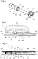
- FIG.1 an inventive safety system 1 for a vehicle seat 50 is shown in a perspective view.
- the safety system 1 comprises a bottom rail 40, which is provided for attachment to a vehicle floor.
- three rail elements 11, 12, 13 are guided displaceably.
- a first rail member 11 and a second rail member 12 are coupled to each other by two locking pins 23 and close in the longitudinal direction of the bottom rail 40 directly to each other.
- a third rail element 13 is arranged at a distance from the second rail element 12.
- the first rail element 11 and the third rail element 13 are connected to one another by a bracket element 14, which belongs to the substructure of a vehicle seat 50. It is understood that normally each of the components shown is to be arranged twice, namely symmetrically on both sides of the seat 50. For the sake of simplicity, only the components of a page are shown here.
- the rail elements 11, 12,13 are mounted by means of ball bearings and sliding inserts 44 on the bottom rail 40 to reduce the friction.
- the second rail element 12 can be locked relative to the floor rail 40.
- the second rail member 12 holes 24, which correspond to a series of holes 41 in the bottom rail 40.
- For locking serve two locking pins 43 which are inserted through a respective bore 24 in the second rail member 12 and a bore 41 in the bottom rail 40.
- the locking pins 43 are unlocked by means not shown here in detail and can then be moved along with their support for adjusting the seat in the longitudinal direction.
- a drive 15 is arranged within the first rail member 11, a drive 15 is arranged.
- This comprises a substantially cylindrical housing 17, in which a drive chamber 18 is formed. The latter is open in the direction of the second rail element 12.
- a micro gas generator 16 is arranged, which can be ignited in a known manner by means not shown electrically.
- Adjacent to the micro gas generator 16 is a piston member 19, which is integrally formed on a rod 20 which extends approximately to the end of the drive chamber 18.
- the arrangement is such that upon activation of the micro gas generator 16, the piston member 19 is acted upon directly with gas pressure.
- the outer cross section of the piston member 19 is adapted to the inner cross section of the drive chamber 18, that results in an at least substantially gas-tight connection.
- a sleeve element 25 and an expanding element 26 engaging in this are arranged on the rod 20.
- the sleeve member 25, which has approximately the shape of a truncated cone, in this case has a first slot 27, which facilitates a spreading.
- the expansion element 26, which has approximately the shape of a truncated cone, has a second slot 28 through which the expansion element 26 can be widened or compressed to a certain extent.
- first rail member 11 is extended like a cheek to engage around the second rail member 12 from the outside.
- the first rail element 11 and the second rail element 12 each have bores 30, 31, the diameter of which corresponds to the locking pin 23.
- said rail elements 11, 12 by means of locking pins 23 which are inserted through the bores 30, 31, positively connected.
- the micro gas generator 16 of the drive 15 is activated. This leads to a pressurization of the piston member 19. Due to the locking pin 23, the position of the first rail member 11 relative to the second rail member 12 is initially secured. However, the piston element 19 presses the guide fork 21 in the direction of the second rail element 12 via the rod 20. By means of the guide slopes 34 of the guide fork 21, the locking bolts 23 are pressed inwards against the force of the spring 22 and thus released from the bores 30, 31 , The lock is thus solved purely mechanically by the action of the drive 15.
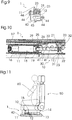
- Fig. 11 schematically shown, wherein the solid lines show the seat 50 and the safety system 1 in the rest position, while the dashed lines illustrate the state after activation of the drive 15.
- the result of the displacement of the first rail element 11 is a displacement of the vehicle seat 50 connected thereto. Its backrest is therefore moved closer to the back of an occupant 60, resulting in a sudden acceleration of the vehicle forward, which accelerates the occupant 60 backward within the vehicle , gives better support in particular of the head and cervical region.
- the vehicle seat 50 should be able to yield to the force acting on the occupant 60 in a rear impact, for example, by moving in a damped manner backwards.
- the sleeve element 25 and the expansion element 26 form a damping element, which is activated when the first rail element 11 is in the outermost position.
- the first rail element 11 has a second stop 33, which is hit by the expansion element 26 when it reaches the outermost position. This second stop 33 stops on the one hand, the displacement of the first rail member 11, on the other hand, thereby the spreader 26 is pushed on the rod 20 in the sleeve member 25 into it.
- the sleeve element 25 Due to the truncated, widening shape of the expansion element 26, the sleeve element 25 is thereby spread open. It is pressed from the inside against the wall of the housing 17. Due to the displacement, the expansion element 26 comes into engagement with an annular groove 29 of the rod 20, the axial dimension of which is matched to the expansion element 26. The necessary for the intervention compression of the expansion element results from the force exerted by the sleeve member 25 counterforce. In addition, the spreader 26 may be biased to a smaller diameter when reaching the groove 29 to accept.
- the piston member 19 and the rod 20 are pressed back toward the micro gas generator 16. Due to the described spreading of the sleeve member 25 results in a strong solid friction between the sleeve member 25 and the housing 17 of the drive chamber 18. In addition, it can lead to a widening of the drive chamber 18. These effects lead to a damping of the movement, so that the vehicle seat 50 with the occupant 60 is guided comparatively gently back in the direction of the rest position.
- the overall result is a combination of rapid forward movement of the seat 50 which places plans for better support close to the occupant 60 and a dampened, slower rearward movement of the seat 50 to yield a force on the occupant 60.
Description
Die Erfindung betrifft ein Sicherheitssystem für einen Fahrzeugsitz.The invention relates to a safety system for a vehicle seat.
Im Fahrzeugbau, insbesondere im Kfz-Bereich, sind verschiedene Sicherheitssysteme bekannt, bei denen im Falle eines Unfalls oder einer Gefahrensituation ein Antrieb auf eine Fahrzeugkomponente einwirkt, um die Sicherheit für die Fahrzeuginsassen zu erhöhen. Hierunter fallen z. B. Gurtstraffer oder Systeme, die Einstellung oder Position eines Fahrzeugsitzes verändern. Ein besonderes Problem stellen in diesem Zusammenhang Unfälle mit Heckaufprall, z. B. Auffahrunfälle, dar. Hierbei erfährt das Fahrzeug eine plötzliche Beschleunigung nach vorne, was bedeutet, dass die Fahrzeuginsassen relativ zum Fahrzeug eine Beschleunigung nach hinten erfahren. Während der Rücken eines Insassen normalerweise zumindest im unteren Bereich an der Rückenlehne des Sitzes anliegt, befindet sich der Kopf in aller Regel in einem gewissen Abstand von der Kopfstütze. Aus diesem Grund, und aufgrund der höheren Biegsamkeit des Halses im Vergleich zum Rumpf, ist der Halsbereich bei derartigen Unfällen besonders gefährdet. Es kann hierbei, auch wenn der Aufprall nur mit vergleichsweise geringer Geschwindigkeit erfolgt, zu einem so genannten Schleudertrauma kommen, das aus einer Überstreckung der Halswirbelsäule resultiert.In vehicle construction, in particular in the motor vehicle sector, various safety systems are known in which, in the case of an accident or a dangerous situation, a drive acts on a vehicle component in order to increase safety for the vehicle occupants. These include z. As belt tensioners or systems that change the setting or position of a vehicle seat. A particular problem in this context accidents with rear impact, z. As rear-end collisions, dar. Here, the vehicle undergoes a sudden acceleration forward, which means that the vehicle occupants experience relative to the vehicle acceleration to the rear. While the back of an occupant usually rests against the backrest of the seat, at least in the lower region, the head is usually located at a certain distance from the headrest. For this reason, and because of the greater flexibility of the neck compared to the hull, the neck area is particularly vulnerable to such accidents. In this case, even if the impact occurs only at a comparatively low speed, a so-called whiplash injury can result, which results from hyperextension of the cervical spine.
Um die plötzliche Beschleunigung des Kopfes gegenüber dem Fahrzeugsitz, die auch als Whiplash-Effekt bezeichnet wird, zu mildern, sind im Stand der Technik Systeme entwickelt worden, bei denen der Fahrzeugsitz so ausgestaltet ist, dass er in einem solchen Fall im Fahrzeug nach hinten gleitet und gegebenenfalls auch gekippt wird. Diese Systeme zielen allein darauf ab, der auf den Insassen wirkenden Beschleunigungskraft nachzugeben. Ein grundsätzliches Problem hierbei ist allerdings, dass die Wegstrecke, entlang der der Sitz verfahren werden kann, begrenzt ist. Hat der Sitz eine Endposition erreicht, können darüber hinaus einwirkende Beschleunigungskräfte dennoch zu Verletzungen des Insassen führen. Des Weiteren ist es schwierig, hierbei den Zeitpunkt und die Geschwindigkeit der Bewegung des Sitzes auf die tatsächlich einwirkende Beschleunigung abzustimmen.In order to mitigate the sudden acceleration of the head relative to the vehicle seat, which is also referred to as whiplash effect, systems have been developed in the prior art in which the vehicle seat is designed such that in such a case it slides backwards in the vehicle and possibly also tilted. These systems are aimed solely at giving in to the acceleration force acting on the occupants. A fundamental problem with this, however, is that the distance along which the seat can be moved is limited. In addition, if the seat has reached an end position, acting acceleration forces can nevertheless lead to injuries to the occupant. Furthermore, it is difficult to match the timing and speed of movement of the seat to the actual acceleration applied.
Aus der
Vor diesem Hintergrund ist es Aufgabe der vorliegenden Erfindung, Maßnahmen zum verbesserten Schutz von Insassen eines Fahrzeugs bei einem Heckaufprall vorzuschlagen.Against this background, it is an object of the present invention to propose measures for the improved protection of occupants of a vehicle in a rear-end collision.
Die Aufgabe wird erfindungsgemäß gelöst durch ein Sicherheitssystem nach Anspruch 1.The object is achieved by a security system according to
Durch die Erfindung wird zum einen ein Sicherheitssystem für einen Fahrzeugsitz zur Verfügung gestellt. Hierbei bezeichnet "Sicherheitssystem" ein System, bei dem in einer Notfallsituation (also bei einem Unfall oder in einer Gefahrensituation) ein Antrieb auf eine Fahrzeugkomponente einwirkt, um die Sicherheit für die Fahrzeuginsassen zu erhöhen. Als Fahrzeuge kommen in diesem Zusammenhang insbesondere Kraftfahrzeuge wie Pkw oder Lkw infrage. Das erfindungsgemäße Sicherheitssystem für einen Fahrzeugsitz umfasst ein Führungselement, das zur verschieblichen Führung an einer Bodenschiene anordenbar ist. Hierbei bezeichnet "Bodenschiene" eine schienenförmige Komponente, die am Fahrzeugboden befestigt ist, und mit der ein Führungselement, das seinerseits mit dem Fahrzeugsitz verbunden ist, derart eingreifen kann, dass der Fahrzeugsitz verschoben werden kann, wobei er durch das Zusammenwirken von Führungselement und Bodenschiene geführt ist. Hierbei können zwischen Führungselement und Bodenschiene ggf. Kugel- oder Rollenlager ausgebildet sein, um die Reibung herabzusetzen. Derartige Systeme sind im Stand der Technik z. B. zur Anpassung der Sitzposition an die Größe des Fahrers bekannt, wobei typischerweise das Führungselement gegenüber der Bodenschiene arretierbar ist, um eine ungewollte Verschiebung des Sitzes zu verhindern. Normalerweise sind pro Fahrzeugsitz zwei Bodenschienen parallel nebeneinander angeordnet, mit denen zwei Führungselemente zusammenwirken. Das Führungselement kann insbesondere einen länglichen, schienenartigen Aufbau haben. Insbesondere in diesem Fall kann das Führungselement auch als "Sitzschiene" oder "Führungsschiene" bezeichnet werden. Im Allgemeinen ist das Führungselement hier durch seine Funktion definiert, nämlich im Zusammenspiel mit einer Bodenschiene eine verschieblich Führung zu gewährleisten.By the invention, on the one hand, a security system for a vehicle seat is provided. Here, "safety system" refers to a system in which, in an emergency situation (ie in the case of an accident or in a dangerous situation), a drive acts on a vehicle component in order to increase safety for the vehicle occupants. Vehicles such as cars or trucks are particularly suitable as vehicles in this context. The safety system according to the invention for a vehicle seat comprises a guide element, which can be arranged on a floor rail for displaceable guidance. Here, "bottom rail" refers to a rail-shaped component which is fastened to the vehicle floor, and with which a guide element, which in turn is connected to the vehicle seat, can engage in such a way that the vehicle seat can be displaced, guided by the interaction of guide element and bottom rail is. Here, between the guide element and bottom rail optionally ball or roller bearings may be formed to reduce the friction. Such systems are known in the art z. B. for adapting the seating position to the size of the driver known, wherein typically the guide member relative to the bottom rail is locked to prevent unwanted displacement of the seat. Normally, two floor rails are arranged parallel to each other per vehicle seat, with which two guide elements interact. The guide element may in particular have an elongate, rail-like structure. In particular, in this case, the guide member may also be referred to as a "seat rail" or "guide rail". In general, the guide element is defined here by its function, namely to ensure a sliding guide in interaction with a bottom rail.
Das Führungselement umfasst hierbei wenigstens ein Schubelement zur Verbindung mit dem Fahrzeugsitz, ein Arretierungselement, das zur Arretierung gegenüber der Bodenschiene ausgebildet ist, sowie einen zwischen dem Schubelement und dem Arretierungselement wirkenden Antrieb. Das Schubelement kann hierbei in bekannter Weise zur Verbindung mit dem Fahrzeugsitz vorgesehen sein, z. B. kann es Bohrungen aufweisen, durch die Schrauben geführt werden, mittels derer eine Verschraubung mit dem Fahrzeugsitz möglich ist. Die Verbindung muss hierbei nicht direkt mit einer Sitzschale des Fahrzeugsitzes erfolgen, vielmehr wird typischerweise das Schubelement z. B. mit der Mechanik einer Höhenverstellung verbunden sein, die ihrerseits mit der Sitzschale verbunden ist.The guide element in this case comprises at least one thrust element for connection to the vehicle seat, a locking element which is designed to lock against the bottom rail, and a force acting between the thrust element and the locking element drive. The thrust element can in this case be provided in a known manner for connection to the vehicle seat, z. B. it may have holes through which screws are guided, by means of which a screw with the vehicle seat is possible. The connection must not be done directly with a seat of the vehicle seat, but is typically the thrust element z. B. connected to the mechanics of a height adjustment, which in turn is connected to the seat.
Das Arretierungselement ist durch im Stand der Technik bekannte Mittel gegenüber der Bodenschiene arretierbar, um eine vom Insassen eingestellte Sitzposition zu fixieren. Hierbei müssen nicht alle hierzu notwendigen Mittel Teil des Arretierungselementes sein. So kann im einfachsten Fall z. B. eine Bohrung im Arretierungselement mit einer Mehrzahl von Bohrungen in der Bodenschiene korrespondieren, wobei die Arretierung erfolgt, indem ein Arretierstift o. Ä. durch zwei Bohrungen hindurch gesteckt wird. Es ist hierbei vorgesehen, dass - wie bei bekannten Führungselementen - eine Position des Fahrzeugsitzes z. B. entsprechend der Größe des Insassen eingestellt und mittels des Arretierungselements fixiert wird. Es versteht sich hierbei, dass die Arretierung durch Einwirkung eines Insassen lösbar sein sollte.The locking element can be locked relative to the floor rail by means known in the art in order to fix a sitting position set by the occupant. Not all necessary means must be part of the locking element here. So in the simplest case z. B. correspond to a hole in the locking element with a plurality of holes in the bottom rail, wherein the locking takes place by a locking pin o. Ä. is inserted through two holes. It is hereby provided that - as with known guide elements - a position of the vehicle seat z. B. adjusted according to the size of the occupant and fixed by means of the locking element. It is understood here that the lock should be solvable by the action of an occupant.
Im Rahmen der Erfindung können noch weitere Elemente zur Führung des Sitzes dienen. So kann z. B. ein weiteres Element zusätzlich zum Arretierungselement und Schubelement vorhanden sein, das mit dem Schubelement nur indirekt über den Fahrzeugsitz verbunden ist.In the context of the invention may serve other elements for guiding the seat. So z. B. a further element in addition to the locking element and thrust element be present, which is connected to the thrust element only indirectly via the vehicle seat.
Der Antrieb wirkt zwischen dem Schubelement und dem Arretierungselement, d. h. er ist dazu ausgebildet, eine Kraft zwischen den beiden genannten Elementen zu vermitteln. Somit sind die beiden Elemente in der Regel wenigstens indirekt über den Antrieb miteinander verbunden. Der Antrieb kann hierbei neben dem eigentlichen Motor, auf dessen Ausgestaltung später noch eingegangen wird, gegebenenfalls auch Getriebekomponenten, Mittel zur Kraftübertragung usw. umfassen.The drive acts between the pusher and the locking element, i. H. he is trained to impart a force between the two mentioned elements. Thus, the two elements are usually connected to each other at least indirectly via the drive. The drive can in this case in addition to the actual engine, on the configuration will be discussed later, if necessary, also include transmission components, means for power transmission, etc.
Erfindungsgemäß ist das Schubelement mittels des Antriebes gegenüber dem Arretierungselement verschiebbar, um den Fahrzeugsitz nach vorne zu bewegen. Das bedeutet, das Schubelement, an dem in eingebautem Zustand der Fahrzeugsitz befestigt ist, kann mittels des Antriebes gegenüber dem Arretierungselement derart bewegt werden, dass hieraus (in eingebautem Zustand) eine Bewegung des Fahrzeugsitzes nach vorne resultiert. Die Verschiebung findet hierbei bevorzugt nur nach vorne statt, kann aber ggf. auch mit einer (geringfügigen) Verschiebung nach oben oder unten kombiniert sein. Ebenfalls ist es bevorzugt, dass das Schubelement entlang der Bodenschiene verschoben wird.According to the invention, the push element is displaceable by means of the drive relative to the locking element in order to move the vehicle seat forward. This means that the thrust element, which is fixed to the vehicle seat in the installed state, can be moved by means of the drive relative to the locking element in such a way that results (in the installed state) a movement of the vehicle seat forward. The shift here preferably takes place only forward, but may possibly also with a (minor) shift to be combined above or below. It is also preferred that the pusher element is displaced along the bottom rail.
Durch das erfindungsgemäße Sicherheitssystem kann in einer Notfallsituation (bei einem Unfall oder gegebenenfalls auch in einer über Sensoren erkannten Gefahrensituation) eine Verlagerung des gesamten Sitzes nach vorne erfolgen. Wenn dies durch einen geeigneten Antrieb schnell genug erfolgt (z. B. innerhalb weniger Millisekunden), so verbleibt ein auf dem Sitz befindlicher Insasse aufgrund der Trägheit währenddessen im Wesentlichen in Position, so dass der Sitz von hinten an den Insassen herangerückt wird. Hierdurch wird die gesamte Rückenlehne mit der daran befindlichen Kopfstütze näher an Rücken und Kopf des Insassen gebracht. Somit verkürzt sich bei einem Aufprall von hinten ein möglicher freier Beschleunigungsweg des Kopfes, woraus eine geringere mögliche Überstreckung und somit ein geringeres Verletzungsrisiko resultiert.Due to the safety system according to the invention, in an emergency situation (in the event of an accident or possibly also in a danger situation detected via sensors), the entire seat can be displaced forward. If this is done quickly enough (for example within a few milliseconds) by a suitable drive, an occupant in the seat will remain substantially in position due to the inertia meanwhile, so that the seat will be moved from behind to the occupant. As a result, the entire backrest is brought closer to the back and head of the occupant with the headrest thereon. Thus, in the event of an impact from behind, a possible free acceleration path of the head is shortened, resulting in a lower possible hyperextension and thus a lower risk of injury.
Besonders vorteilhaft ist hierbei, dass sich das erfindungsgemäße Sicherheitssystem ohne größere Probleme in bekannte Sitzsysteme integrieren lässt. Insbesondere sind keinerlei Modifikationen im Bereich der Sitzschale oder Rückenlehne notwendig. Das gesamte Führungselement einschließlich des Antriebes lässt sich, wie noch dargestellt wird, hinreichend kompakt ausführen, dass es im Prinzip ohne weitere Modifikationen der angrenzenden Komponenten in ein bestehendes System integriert werden kann.It is particularly advantageous that the safety system according to the invention can be integrated without major problems in known seating systems. In particular, no modifications in the area of the seat or backrest are necessary. As will be shown, the entire guide element including the drive can be made sufficiently compact that, in principle, it can be integrated into an existing system without further modifications of the adjacent components.
Es ist hierbei nicht notwendig, dass sowohl das Schubelement als auch das Arretierungselement derart ausgebildet sind, dass eine Führung an bzw. innerhalb der Bodenschiene gegeben ist. Da üblicherweise die beiden Elemente beim Normalbetrieb des Fahrzeuges einen Verbund bilden, ist es für die Führung des Sitzes ausreichend, wenn eines der beiden Elemente in der dargestellten Weise ausgebildet ist. Bevorzugt sind allerdings beide Elemente zur verschieblichen Führung an der Bodenschiene ausgebildet.It is not necessary in this case that both the thrust element and the locking element are formed such that a guide is given to or within the bottom rail. Since usually form the two elements during normal operation of the vehicle, it is sufficient for the guidance of the seat when one of the two elements is formed in the manner shown. However, both elements are preferably designed for displaceable guidance on the bottom rail.
Grundsätzlich kann die Verschiebung des Schubelements durch Zug oder Schub erreicht werden. Gemäß einer Ausgestaltung der Erfindung ist der Antrieb dazu eingerichtet, das Schubelement zu schieben. D. h. im eingebauten Zustand befindet sich das Arretierungselement (wenigstens teilweise) hinter dem Schubelement und der Antrieb ist dazu vorgesehen, das Schubelement nach vorne zu drücken. Daneben ist das erfindungsgemäß aber auch denkbar, dass der Antrieb dazu eingerichtet ist, das Schubelement zu ziehen. In jeder der genannten Ausgestaltungen ist es denkbar, dass ein Motor (bzw. Krafterzeuger) des Antriebs am Schubelement oder am Arretierungselement angeordnet ist.In principle, the displacement of the push element can be achieved by train or push. According to one embodiment of the invention, the drive is adapted to push the pusher. Ie. when installed, the locking element is (at least partially) behind the pusher and the drive is intended to push the pusher forward. In addition, the invention is also conceivable that the drive is adapted to pull the pusher. In each of the mentioned embodiments it is conceivable that a motor (or force generator) of the drive is arranged on the thrust element or on the locking element.
Im Normalbetrieb des Fahrzeuges ist es wünschenswert, dass keinerlei Verschiebung zwischen dem Arretierungselement und dem Schubelement stattfindet. Es sind hierbei Ausführungsformen denkbar, in denen der Antrieb z. B. aufgrund eines inneren Reibungswiderstandes derartige Verschiebungen verhindert, solange er nicht aktiviert wird. Vorteilhaft umfasst allerdings das Führungselement ein zwischen Arretierungselement und Schubelement wirkendes Verriegelungselement. Durch ein solches Verriegelungselement kann die Relativpositionen zwischen Arretierungselement und Schubelement gesichert werden. Ein solches Verriegelungselement ist hierbei lösbar ausgebildet, d. h. es kann entriegelt werden. Die Verriegelung kann hierbei insbesondere durch eine formschlüssige Verbindung erreicht werden, bei der z. B. einen zapfenförmiges Element auf Seiten des Arretierungselements in eine entsprechende Ausnehmung auf Seiten des Schubelements eingreift oder umgekehrt.During normal operation of the vehicle, it is desirable that no displacement between the locking element and the pusher takes place. In this case, embodiments are conceivable in which the drive z. B. due to an internal friction resistance prevents such shifts, as long as it is not activated. Advantageously, however, the guide element comprises a locking element acting between the locking element and the pushing element. By such a locking element, the relative positions between the locking element and pushing element can be secured. Such a locking element is in this case detachably formed, d. H. it can be unlocked. The locking can in this case be achieved in particular by a positive connection in which z. B. engages a pin-shaped element on the side of the locking element in a corresponding recess on the side of the thrust element or vice versa.
Bei Vorhandensein eines Verriegelungselements ist es notwendig, dass dieses zuverlässig entriegelt wird, wenn das Schubelement verschoben werden soll. Dies kann zum einen über eine übergeordnete Steuerung, die auch den Antrieb auslöst, geschehen. Es ist allerdings bevorzugt, dass das Verriegelungselement durch Einwirkung des Antriebs lösbar ist. In diesem Fall wirkt der Antrieb, der auch die Verschiebung des Schubelements bewirkt, direkt oder indirekt derart auf das Verriegelungselement ein, dass dieses gelöst bzw. entriegelt wird. Der Antrieb wirkt hierbei bevorzugt rein mechanisch auf das Verriegelungselement ein. Auf diese Weise kann eine Fehlfunktion des Verriegelungselements weitgehend ausgeschlossen werden. Darüber hinaus lässt sich hierdurch mit einfachen Mitteln der Entriegelungsvorgang zeitlich auf den Verschiebungsvorgang abstimmen.In the presence of a locking element, it is necessary that this is reliably unlocked when the thrust element is to be moved. This can happen on the one hand via a higher-level control, which also triggers the drive. However, it is preferred that the locking element is releasable by the action of the drive. In this case, the drive, which also causes the displacement of the thrust element acts directly or indirectly on the locking element, that this is released or unlocked. The drive here preferably acts purely mechanically on the locking element. In this way, a malfunction of the locking element can be largely excluded. In addition, this can be timed to adapt to the displacement process with simple means of unlocking.
Der Antrieb kann im Rahmen der Erfindung verschiedenartig funktionieren, z. B. elektrisch, hydraulisch oder pneumatisch. Diese Antriebsformen haben den Vorteil, dass sich die Verschiebung gut kontrollieren lässt, bedingen aber unter Umständen einen relativ hohen Installationsaufwand und lassen sich nur schwer kompakt realisieren, wenn eine hohe Antriebsleistung bzw. schnelle Auslösung erreicht werden soll. Daher umfasst der Antrieb in einer bevorzugten Ausgestaltung der Erfindung einen pyrotechnischen Gasgenerator. Derartige Vorrichtungen sind im Kfz-Bereich z.B. bei Airbags und anderen Sicherheitssystemen bekannt. Im Allgemeinen bezeichnet "pyrotechnischer Gasgenerator" hierbei jede Vorrichtung, in der gezielt eine chemische Reaktion auslösbar ist, die zur Gasentwicklung führt, typischerweise in Form einer Explosion oder eines gezielten Abbrands. In Kombination hiermit können auch Kartuschen mit vorgespanntem Gas verwendete werden, bei denen z. B. ein pyrotechnischer Gasgenerator eine Berstscheibe zerstört und damit den Zustrom von Gas aus der Kartusche zur Antriebseinheit freigibt. Derartige Vorrichtungen sind auch als Hybridgasgeneratoren bekannt. Bei der chemischen Reaktion, die der Funktion des pyrotechnischen Gasgenerators zugrunde liegt, wird extrem schnell Energie freigesetzt und steht für den Antrieb zur Verfügung, was insbesondere bei Unfällen einen entscheidenden Sicherheitsvorteil bedeutet. In jedem Fall impliziert die Verwendung für ein Sicherheitssystem, dass der Antrieb in der Lage sein muss, die vorgesehene Verschiebung, die im Bereich von einigen Zentimetern liegt, innerhalb von deutlich weniger als 1 Sekunde durchzuführen. Insbesondere dann, wenn der Antrieb bei einem Unfall zum Einsatz kommt, sind kurze Verschiebungszeiten von unter 100 Millisekunden, bevorzugt unter 20 Millisekunden, weiter bevorzugt unter 10 Millisekunden, typisch.The drive can function differently in the invention, for. B. electrically, hydraulically or pneumatically. These drive forms have the advantage that the shift can be well controlled, but may require a relatively high installation effort and can be difficult to achieve compact, if a high drive power or rapid release should be achieved. Therefore, in a preferred embodiment of the invention, the drive comprises a pyrotechnic gas generator. Such devices are known in the automotive sector, for example in airbags and other security systems. Generally referred to "Pyrotechnic gas generator" here any device in which a targeted chemical reaction is triggered, which leads to gas evolution, typically in the form of an explosion or a targeted burnup. In combination with this can also be used with biased gas cartridges in which z. B. a pyrotechnic gas generator destroys a rupture disk and thus releases the influx of gas from the cartridge to the drive unit. Such devices are also known as hybrid gas generators. The chemical reaction that underlies the function of the pyrotechnic gas generator releases energy extremely quickly and is available for propulsion, which means a decisive safety advantage, especially in the event of accidents. In any event, use for a safety system implies that the drive must be able to perform the intended displacement, which is in the range of a few centimeters, in well less than 1 second. In particular, when the drive is used in an accident, short shift times of less than 100 milliseconds, preferably less than 20 milliseconds, more preferably less than 10 milliseconds, are typical.
In einer bevorzugten Ausgestaltung der Erfindung umfasst der Antrieb eine Antriebskammer sowie ein hierin verschiebbar angeordnetes Kolbenelement, das durch Druckbeaufschlagung antreibbar ist. Die Antriebskammer bildet hierbei einen Hohlraum, der bevorzugt zumindest abschnittsweise einen gleich bleibenden Innenquerschnitt aufweist. Der genannte Innenquerschnitt kann insbesondere kreisförmig sein, aber ggf. auch rechteckig, polygonal, oval usw. Das Kolbenelement kann in diesem Bereich verschoben werden. Der Querschnitt des Kolbenelements ist hierbei bevorzugt auf den Innenquerschnitt der Antriebskammer abgestimmt. Wird ein Gas oder eine Flüssigkeit an einem Ende der Antriebskammer mit Druck beaufschlagt, so wird das Kolbenelement hierdurch angetrieben. Die hierdurch vermittelte Kraft kann durch eine am Kolbenelement angeordnete Stange oder Ähnliches weiterübertragen werden. So kann z. B. ein Gehäuse, in dem die Antriebskammer ausgebildet ist, fest mit dem Schubelement verbunden sein und die Stange kann am Arretierungselement angreifen, um das Schubelement zu verschieben.In a preferred embodiment of the invention, the drive comprises a drive chamber and a piston element arranged displaceably therein, which can be driven by pressurization. The drive chamber in this case forms a cavity, which preferably at least partially has a constant inner cross section. Said inner cross section may in particular be circular, but possibly also rectangular, polygonal, oval, etc. The piston element may be displaced in this area. The cross section of the piston element is in this case preferably matched to the inner cross section of the drive chamber. If a gas or a liquid is pressurized at one end of the drive chamber, the piston element is thereby driven. The force mediated thereby can be further transmitted by a rod arranged on the piston member or the like. So z. As a housing in which the drive chamber is formed, be firmly connected to the thrust element and the rod can engage the locking element to move the thrust element.
Ein solches System mit Antriebskammer und Kolbenelement kann insbesondere mit einem pyrotechnischen Gasgenerator kombiniert werden, wobei der Gasgenerator in bzw. an der Antriebskammer oder zumindest in Verbindung mit dieser angeordnet ist, so dass das Kolbenelement durch den Gasgenerator mit Gasdruck beaufschlagbar ist. Daneben kann das Kolbenelement selbstverständlich auch pneumatisch oder hydraulisch betätigt werden.Such a system with drive chamber and piston element can be combined in particular with a pyrotechnic gas generator, wherein the gas generator is arranged in or on the drive chamber or at least in connection with this, so that the piston element can be acted upon by the gas generator with gas pressure. In addition, the piston element can of course also be operated pneumatically or hydraulically.
Wird diese Ausführungsform mit einem Verriegelungselement kombiniert, ist es bevorzugt, dass das Kolbenelement dazu eingerichtet ist, mittels einer Stange auf das Verriegelungselement einzuwirken. Die Stange dient hierbei dazu, eine auf das Kolbenelement wirkende Kraft zu übertragen. Diese in Richtung der Bewegung des Kolbenelements gerichtete Kraft kann durch geeignete Mittel, z. B. eine Führungsschräge, zur Erzeugung von senkrecht hier zu wirkenden Kräften verwendet werden, z. B. um ein Verriegelungselement aus einer formschlüssigen Verbindungen herauszuziehen bzw. herauszudrücken.If this embodiment is combined with a locking element, it is preferred that the piston element is adapted to act on the locking element by means of a rod. The rod serves to transmit a force acting on the piston element force. This directed in the direction of movement of the piston member force can by suitable means, for. As a guide bevel, are used to generate forces acting vertically here, z. B. to extract a locking element from a positive connections or push out.
Wenngleich durch das Führungselement des erfindungsgemäßen Sicherheitssystems ein Fahrzeugsitz schnell und effektiv vorwärts bewegt werden kann, um eine verbesserte Stützwirkung für einen Insassen zu erreichen, ist zu bedenken, dass die auf das Fahrzeug bewirkende Beschleunigung bei einem Heckaufprall noch länger andauern kann. Für diesen Fall kann zusätzlich zum Verschieben des Fahrzeugsitzes nach vorne vorgesehen sein, ihn sich anschließend rückwärts bewegen zu lassen, der einwirkenden Kraft folgend. Durch diese Maßnahme, die an sich im Stand der Technik bereits bekannt ist, kann ein Verletzungsrisiko für den Insassen weiter reduziert werden. Es hat sich hierbei allerdings gezeigt, dass die Rückbewegung nicht unkontrolliert, sondern gebremst stattfinden sollte. Aus diesem Grund umfasst der Antrieb vorzugsweise ein Dämpfungselement zur Dämpfung einer Rückbewegung, die einer Vorwärtsbewegung durch den Antrieb entgegengesetzt ist. Der Begriff "Vorwärtsbewegung" bezieht sich hier selbstverständlich auf die normale Einbauposition, in der der Antrieb eine entsprechende Bewegung des Schubelements und somit des Fahrzeugsitzes erzeugt. Bei der oben geschilderten Variante einer Antriebskammer mit Kolbenelement kann bereits das Kolbenelement als Dämpfungselement wirken, da es bei der Rückbewegung in den Antriebskammer ein darin befindliches Gas bzw. eine Flüssigkeit komprimiert bzw. einen Strömungswiderstand ausgesetzt ist. Eine Dämpfung kann allerdings auch z. B. durch Festkörperreibung oder durch eine Wirbelstrombremse erfolgen.Although a vehicle seat can be moved forward quickly and effectively by the guide element of the safety system according to the invention in order to achieve an improved support effect for an occupant, it is to be considered that the acceleration on the vehicle can last even longer in a rear impact. For this case, in addition to moving the vehicle seat can be provided forward, then let him move backwards, following the applied force. By this measure, which is already known per se in the prior art, a risk of injury to the occupant can be further reduced. However, it has been shown here that the return movement should not take place unchecked, but braked. For this reason, the drive preferably comprises a damping element for damping a return movement, which is opposite to a forward movement by the drive. Of course, the term "forward movement" here refers to the normal installation position in which the drive generates a corresponding movement of the push element and thus of the vehicle seat. In the above-described variant of a drive chamber with a piston element, the piston element can already act as a damping element, since it compresses a gas or a liquid therein during the return movement into the drive chamber or is exposed to a flow resistance. A damping can, however, also z. B. done by solid friction or by an eddy current brake.
Um zu vermeiden, dass die Verschiebung des Schubelements mittels des Antriebes durch das Dämpfungselement behindert wird, ist es besonders vorteilhaft, wenn dessen Einwirkung sich vornehmlich auf die Rückbewegung beschränkt. Daher vorzugsweise vorgesehen, dass das Dämpfungselement im Bereich des Übergangs zur Rückbewegung aktivierbar ist. Dies beinhaltet sowohl Ausführungsformen, bei denen die Aktivierung gleichzeitig mit dem Übergang zur Rückbewegung stattfindet als auch solche, bei denen die Aktivierung (kurz) davor bzw. danach erfolgt. Als Aktivierung gilt in diesem Zusammenhang jede Veränderung des Dämpfungselements, durch die sich die dämpfende Wirkung desselben verstärkt.In order to avoid that the displacement of the thrust element by means of the drive is hindered by the damping element, it is particularly advantageous if its action is limited primarily to the return movement. Therefore, it is preferably provided that the damping element can be activated in the region of the transition to the return movement. This includes both embodiments in which the activation takes place simultaneously with the transition to the return movement as well as those in which the activation (shortly) before or after he follows. Activation in this context is any change in the damping element, which amplifies the damping effect of the same.
Besonders bevorzugt ist es hierbei, dass das Dämpfungselement durch Einwirkung des Antriebs aktivierbar ist. In diesem Fall entfällt wiederum eine übergeordnete Steuerung zur Aktivierung des Dämpfungselements, die einen zusätzlichen Installationsaufwand sowie gegebenenfalls eine höhere Fehleranfälligkeit mit sich bringen würde. Bei dieser Ausführungsform wird durch die Aktivierung des Antriebs (mit zeitlicher Verzögerung) die Aktivierung des Dämpfungselements ausgelöst. Die Aktivierung erfolgt in diesem Zusammenhang bevorzugt rein mechanisch, z. B. dadurch dass der Antrieb das Dämpfungselement gegen einen feststehenden Anschlag drückt.It is particularly preferred in this case that the damping element can be activated by the action of the drive. In this case, in turn eliminates a higher-level control to activate the damping element, which would bring an additional installation effort and possibly a higher error rate. In this embodiment, the activation of the damping element is triggered by the activation of the drive (with a time delay). The activation takes place in this context preferably purely mechanical, z. B. in that the drive presses the damping element against a fixed stop.
Gemäß einer besonders bevorzugten Ausgestaltung ist hierbei das Dämpfungselement am Kolbenelement ausgebildet und weist ein Manschettenelement sowie ein Spreizelement auf. ein solches Manschettenelement kann hierbei insbesondere ringförmig bzw. zylindermantelförmig ausgestaltet sein. In jedem Fall weist es im Inneren eine Ausnehmung auf, in die das Spreizelement eingeschoben werden kann. Letzteres hat vorteilhaft eine sich in Richtung der Einschubbewegung verjüngende Form, so dass beim Einschieben das Manschettenelement eine nach außen gerichtete Kraft erfährt, die das Manschettenelement ausweitet. Hierzu kann das Manschettenelement insbesondere einen oder mehrere Dehnungsschlitze aufweisen oder kann aus einem Material erhöhter Elastizität bestehen. Jedenfalls ist bei dieser Ausgestaltung das Spreizelement dazu eingerichtet, durch Zusammenwirken mit einem Anschlag in das Manschettenelement eingeschoben zu werden, um dieses aufzuweiten. Hierbei ist zum einen denkbar, dass eine Bewegung des Manschettenelements durch den Anschlag gestoppt wird, während sich das Spreizelement weiterbewegt, insbesondere durch den Antrieb angetrieben. Zum anderen ist umgekehrt denkbar, dass das Spreizelement durch den Anschlag gestoppt wird, während sich das Manschettenelement demgegenüber weiterbewegt. Besonders bevorzugt ist hierbei der Außenquerschnitt des Manschettenelements auf den Innenquerschnitt der Antriebskammer abgestimmt, so dass sich vor der Aufweitung keine Festkörperreibung zwischen Manschettenelement und Antriebskammer ergibt, während es nach der Aufweitung zu einer solchen Festkörperreibung kommt. Gegebenenfalls kann das Manschettenelement sogar dazu ausgebildet sein, die Antriebskammer aufzuweiten.According to a particularly preferred embodiment, in this case the damping element is formed on the piston element and has a sleeve element and a spreading element. Such a sleeve element can in this case be configured in particular annular or cylindrical jacket-shaped. In any case, it has a recess in the interior, in which the expansion element can be inserted. The latter advantageously has a shape tapering in the direction of the insertion movement, so that upon insertion the collar element experiences an outwardly directed force which expands the collar element. For this purpose, the sleeve element may in particular have one or more expansion slots or may consist of a material of increased elasticity. In any case, in this embodiment, the expansion element is adapted to be inserted by cooperation with a stop in the sleeve member to widen it. In this case, it is conceivable on the one hand that a movement of the sleeve element is stopped by the stop while the spreading element continues to move, in particular driven by the drive. On the other hand, conversely, it is conceivable that the expansion element is stopped by the stop, while the sleeve element moves on the other hand. Particularly preferably, in this case, the outer cross section of the sleeve member is matched to the inner cross section of the drive chamber, so that there is no solid friction between sleeve member and drive chamber before expansion, while it comes after the expansion to such solid friction. Optionally, the sleeve member may even be configured to widen the drive chamber.
Das erfindungsgemäße Sicherheitssystem kann selbstverständlich auch eine mit einem Fahrzeugboden fest verbindbaren Bodenschiene umfassen, wobei das Führungselement an der Bodenschiene angeordnet und verschieblich geführt ist. Wie bereits erwähnt, können zwischen den genannten Elementen auch Kugel- oder Rollenlager angeordnet sein. Es können auch noch weitere Komponenten Teil des Sicherheitssystems sein, z. B. Sensoren, Steuerkomponenten oder eine Stromversorgung.The safety system according to the invention may of course also comprise a bottom rail which can be fixedly connected to a vehicle floor, wherein the guide element is arranged on the bottom rail and guided in a displaceable manner. As already mentioned, spherical or roller bearings can also be arranged between said elements. There may also be other components part of the security system, z. As sensors, control components or a power supply.
Details der Erfindungen werden im Folgenden anhand eines Ausführungsbeispiels mit Bezug auf die Figuren erläutert. Hierbei zeigt
- Fig.1
- eine perspektivische Darstellung einer Ausführungsform eines erfindungsgemäßen Sicherheitssystems für einen Fahrzeugsitz in Ruheposition;
- Fig.2
- eine Seitenansicht des Sicherheitssystems aus
Fig.1 ; - Fig.3
- eine Seitenansicht aus der Richtung III in
Fig.2 ; - Fig.4
- eine Schnittdarstellung gemäß der Linie IV-IV
Fig.2 ; - Fig.5
- eine vergrößerte Detailansicht von
Fig.3 ; - Fig.6
- eine perspektivische Darstellung eines Kolbenelements sowie eines Verriegelungselements des Sicherheitssystems aus
Fig.1 . - Fig.7
- eine Seitenansicht des Sicherheitssystems aus
Fig.1 in aktivierter Position; - Fig.8
- eine Schnittdarstellung gemäß der Linie VIII-VIII in
Fig.7 ; - Fig.9
- eine Schnittdarstellung gemäß der Linie IX-IX in
Fig.8 ; - Fig.10
- eine vergrößerte Detailansicht von
Fig.9 ; sowie - Fig.11
- eine stark schematisierte Seitenansicht eines Fahrzeugsitzes mit dem Sicherheitssystem aus
Fig.1 sowie eines Insassen.
- Fig.1
- a perspective view of an embodiment of a safety system according to the invention for a vehicle seat in the rest position;
- Fig.2
- a side view of the security system
Fig.1 ; - Figure 3
- a side view from the direction III in
Fig.2 ; - Figure 4
- a sectional view according to the line IV-IV
Fig.2 ; - Figure 5
- an enlarged detail view of
Figure 3 ; - Figure 6
- a perspective view of a piston member and a locking element of the security system from
Fig.1 , - Figure 7
- a side view of the security system
Fig.1 in activated position; - Figure 8
- a sectional view according to the line VIII-VIII in
Figure 7 ; - Figure 9
- a sectional view along the line IX-IX in
Figure 8 ; - Figure 10
- an enlarged detail view of
Figure 9 ; such as - Figure 11
- a highly schematic side view of a vehicle seat with the security system out
Fig.1 as well as an occupant.
In
Wie aus der Seitenansicht in
Die Schnittdarstellungen in
Angrenzend an das Kolbenelement 19 sind auf der Stange 20 ein Manschettenelement 25 und ein in dieses eingreifendes Spreizelement 26 angeordnet. Das Manschettenelement 25, welches in etwa die Form eines Kegelstumpfsmantels hat, weist hierbei einen ersten Schlitz 27 auf, der eine Aufspreizung erleichtert. Das Spreizelement 26, das in etwa die Form eines Kegelstumpfs hat, weist einen zweiten Schlitz 28 auf, durch den sich das Spreizelement 26 in gewissem Maße aufweiten oder komprimieren lässt.Adjacent to the
An einem dem Kolbenelement 19 abgewandten Ende der Stange 20 ist diese fest mit einer Führungsgabel 21 verbunden. Diese weist seitlich zwei Führungsschrägen 34 für die Arretierungsbolzen 23 auf. Zwischen den Arretierungsbolzen 23 ist eine Feder 22 angeordnet, die diese kraftbeaufschlagt und so in Position hält. In dem Bereich, in dem die Arretierungsbolzen 23 in der Ruheposition angeordnet sind, ist das erste Schienenelement 11 wangenartig erweitert, um das zweite Schienenelement 12 von außen zu umgreifen. Das erste Schienenelement 11 und das zweite Schienenelement 12 weisen hierbei jeweils Bohrungen 30, 31 auf, deren Durchmesser dem der Arretierungsbolzen 23 entspricht. In der in
Wird durch (nicht dargestellte) Sensoren eines Fahrzeugs einen Heckaufprall bzw. das Bevorstehen eines solchen erkannt, so wird der Mikrogasgenerator 16 des Antriebs 15 aktiviert. Dies führt zu einer Druckbeaufschlagung des Kolbenelements 19. Aufgrund der Arretierungsbolzen 23 ist die Lage des ersten Schienenelements 11 gegenüber dem zweiten Schienenelement 12 zunächst gesichert. Allerdings drückt das Kolbenelement 19 über die Stange 20 die Führungsgabel 21 in Richtung auf das zweite Schienenelement 12. Mittels der Führungsschrägen 34 der Führungsgabel 21 werden die Arretierungsbolzen 23 hierbei entgegen der Kraft der Feder 22 nach innen gedrückt und so aus den Bohrungen 30, 31 gelöst. Die Arretierung wird also rein mechanisch durch Einwirkung des Antriebes 15 gelöst.If a rear impact or the imminence of such is detected by sensors (not shown) of a vehicle, the
Auf einer kurzen Wegstrecke bewegt sich das System mit Kolbenelement 19 und Stange 20 weiter, bis die Führungsgabel 21 auf einen zentral im zweiten Schienenelement 12 angeordneten ersten Anschlag 32 trifft. Dieser bildet nunmehr ein Widerlager, weshalb die weitere Einwirkung des Antriebs 15 dazu führt, dass das erste Schienenelement 11 vom zweiten Schienenelement 12 weg geschoben wird. In
Die Wirkung auf den Fahrzeugsitz 50 ist in
Bei der dargestellten Ausführungsform ist keine Arretierung des ersten Schienenelements 11 in der ausgefahrenen Position vorgesehen. Vielmehr soll der Fahrzeugsitz 50 in der Lage sein, der beispielsweise bei einem Heckaufprall auf den Insassen 60 wirkenden Kraft nachzugeben, indem er sich gedämpft rückwärts bewegt. Hierzu bilden das Manschettenelement 25 und das Spreizelement 26 ein Dämpfungselement, das aktiviert wird, wenn sich das erste Schienenelement 11 in der äußersten Position befindet. Hierzu weist das erste Schienenelement 11 einen zweiten Anschlag 33 auf, auf den das Spreizelement 26 bei Erreichen der äußersten Position trifft. Dieser zweite Anschlag 33 stoppt zum einen die Verschiebung des ersten Schienenelements 11, zum anderen wird hierdurch das Spreizelement 26 auf der Stange 20 in das Manschettenelement 25 hinein geschoben. Aufgrund der kegelstumpfartigen, sich erweiternden Form des Spreizelements 26 wird das Manschettenelement 25 hierdurch aufgespreizt. Es wird hierbei von innen gegen die Wandung des Gehäuses 17 gedrückt. Durch die Verschiebung kommt das Spreizelement 26 in Eingriff mit einer ringförmigen Nut 29 der Stange 20, deren axiale Abmessung auf das Spreizelement 26 abgestimmt. Die für das Eingreifen notwendige Kompression des Spreizelements resultiert hierbei aus der vom Manschettenelement 25 ausgeübten Gegenkraft. Zusätzlich kann das Spreizelement 26 vorgespannt sein, um bei Erreichen der Nut 29 einen geringeren Durchmesser anzunehmen.In the illustrated embodiment, no locking of the
Bei einer Rückwärtsbewegung des Schienenelements 11 in Richtung auf das zweite Schienenelement 12 werden das Kolbenelement 19 und die Stange 20 zurück in Richtung auf den Mikrogasgenerator 16 gedrückt. Aufgrund der beschriebenen Aufspreizung des Manschettenelementes 25 ergibt sich eine starke Festkörperreibung zwischen dem Manschettenelement 25 und dem Gehäuse 17 der Antriebskammer 18. Darüber hinaus kann es zu einer Aufweitung der Antriebskammer 18 kommen. Diese Effekte führen zu einer Dämpfung der Bewegung, so dass der Fahrzeugsitz 50 mit dem Insassen 60 vergleichsweise sanft zurück in Richtung der Ruheposition geführt wird. Es ergibt sich also insgesamt eine Kombination einer schnellen Vorwärtsbewegung des Sitzes 50, durch die Pläne zur besseren Abstützung nahe an den Insassen 60 gerückt wird und einer gedämpften, langsameren Rückwärtsbewegung des Sitzes 50, durch die einer auf den Insassen 60 wirkenden Kraft nachgegeben wird.Upon a backward movement of the
- 11
- Sicherheitssystemsecurity system
- 1010
- Führungselementguide element
- 1111
- erstes Schienenelementfirst rail element
- 1212
- zweites Schienenelementsecond rail element
- 1313
- drittes Schienenelementthird rail element
- 1414
- Bügelelementbracket element
- 1515
- Antriebdrive
- 1616
- MikrogasgeneratorMicro gas generator
- 1717
- Gehäusecasing
- 1818
- Antriebskammerdrive chamber
- 1919
- Kolbenelementpiston element
- 2020
- Stangepole
- 2121
- Führungsgabelguide fork
- 2222
- Federfeather
- 2323
- Arretierungsbolzenlocking bolt
- 2424
- Bohrungdrilling
- 2525
- Manschettenelementcollar member
- 2626
- Spreizelementspreader
- 2727
- erster Schlitzfirst slot
- 2828
- zweiter Schlitzsecond slot
- 2929
- ringförmige Nutannular groove
- 3030
- Bohrungdrilling
- 3131
- Bohrungdrilling
- 3232
- erster Anschlagfirst stop
- 3333
- zweiter Anschlagsecond stop
- 3434
- Führungsschrägeguide slope
- 4040
- Bodenschienebottom track
- 4141
- Bohrungdrilling
- 4242
- Bohrungdrilling
- 4343
- Arretierstiftlocking pin
- 4444
- Kugellager, GleitlagerBall bearings, plain bearings
- 5050
- Fahrzeugsitzvehicle seat
- 6060
- Insasseinmate
Claims (13)
- A safety system (1) for a vehicle seat (50), having a seat rail which is constructed as a guide element (10) and has at least two rail elements (11, 12) which can be arranged for displaceable guidance on a floor rail (40) and which comprises at least- one rail element, constructed as a slide element, (11) for connection to the vehicle seat (50),- one rail element, which is constructed as an arresting element (12) and is designed for an arresting action with respect to the floor rail (40), and- one drive (15) acting between the slide element (11) and the arresting element (12),wherein the slide element (11) can be displaced with respect to the arresting element (12) by means of the drive (15) in order to move the vehicle seat forwards.
- A safety system according to Claim 1, characterised in that both the slide element (11) and the arresting element (12) are designed for displaceable guidance on the floor rail (40).
- A safety system according to one of the preceding claims, characterised in that the drive (15) is designed to move the slide element (11).
- A safety system according to one of the preceding claims, characterised by a locking element (21, 22, 23) acting between the arresting element (12) and the slide element (11).
- A safety system according to Claim 4, characterised in that the locking element (21, 22, 23) can be released by operation of the drive (15).
- A safety system according to one of the preceding claims, characterised in that the drive (15) comprises a pyrotechnic gas generator (16).
- A safety system according to one of the preceding claims, characterised in that the drive (15) comprises a drive chamber (18) and a piston element (19) which is displaceably arranged in said drive chamber and can be driven by the application of pressure.
- A safety system according to Claim 5 and 7, characterised in that the piston element (19) is designed to act on the locking element (21, 22, 23) by means of a rod (20).
- A safety system according to one of the preceding claims, characterised in that the drive (15) comprises a damping element (25, 26) for damping a backwards movement which is contrary to a forwards movement by means of the drive (15).
- A safety system according to Claim 9, characterised in that the damping element (25, 26) can be activated in the region of the transition to the backwards movement.
- A safety system according to Claim 9 or 10, characterised in that the damping element (25, 26) can be activated by operation of the drive (15).
- A safety system according to one of Claims 9 to 11, characterised in that the damping element (25, 26) is constructed on the piston element (19) and has- a sleeve element (25) and- an expansion element (26),wherein the expansion element (25, 26) is designed to be inserted into the sleeve element (25) through cooperation with a stop (32) in order to expand said sleeve element.
- A safety system according to one of the preceding claims, characterised by a floor rail (40) which can be fixedly connected to a vehicle floor, wherein the guide element (10) is arranged and displaceably guided on the floor rail (40).
Priority Applications (1)
| Application Number | Priority Date | Filing Date | Title |
|---|---|---|---|
| EP12007231.9A EP2722221B1 (en) | 2012-10-19 | 2012-10-19 | Safety system for a vehicle seat |
Applications Claiming Priority (1)
| Application Number | Priority Date | Filing Date | Title |
|---|---|---|---|
| EP12007231.9A EP2722221B1 (en) | 2012-10-19 | 2012-10-19 | Safety system for a vehicle seat |
Publications (2)
| Publication Number | Publication Date |
|---|---|
| EP2722221A1 EP2722221A1 (en) | 2014-04-23 |
| EP2722221B1 true EP2722221B1 (en) | 2017-02-15 |
Family
ID=47225864
Family Applications (1)
| Application Number | Title | Priority Date | Filing Date |
|---|---|---|---|
| EP12007231.9A Not-in-force EP2722221B1 (en) | 2012-10-19 | 2012-10-19 | Safety system for a vehicle seat |
Country Status (1)
| Country | Link |
|---|---|
| EP (1) | EP2722221B1 (en) |
Families Citing this family (3)
| Publication number | Priority date | Publication date | Assignee | Title |
|---|---|---|---|---|
| CN108215947B (en) * | 2018-01-05 | 2020-05-19 | 安徽久利昌机械有限公司 | Automobile seat with buffer device |
| CN111251843B (en) * | 2020-01-19 | 2021-08-20 | 长安大学 | Passenger car escape device with movable seat matched with slide type safety door |
| DE102021106873A1 (en) | 2021-03-19 | 2022-09-22 | Bayerische Motoren Werke Aktiengesellschaft | vehicle seat console and vehicle seat |
Family Cites Families (3)
| Publication number | Priority date | Publication date | Assignee | Title |
|---|---|---|---|---|
| DE4415467C1 (en) * | 1994-05-03 | 1995-11-23 | Daimler Benz Ag | Safety belt device for motor vehicles |
| EP2487064B1 (en) * | 2011-03-04 | 2014-09-17 | Metalsa Automotive GmbH | Vehicle seat holder |
| DE102011122384A1 (en) * | 2011-12-24 | 2012-09-13 | Daimler Ag | Device for occupant protection in vehicle, has vehicle seat with seat cushion, seat backrest and head rest, where vehicle seat is moved translationally or rotationally in collision direction by an actuator |
-
2012
- 2012-10-19 EP EP12007231.9A patent/EP2722221B1/en not_active Not-in-force
Non-Patent Citations (1)
| Title |
|---|
| None * |
Also Published As
| Publication number | Publication date |
|---|---|
| EP2722221A1 (en) | 2014-04-23 |
Similar Documents
| Publication | Publication Date | Title |
|---|---|---|
| DE10003853B4 (en) | Vehicle seat with a movable safety crossbar | |
| DE19938938B4 (en) | The vehicle occupant protection system | |
| DE102006061427B4 (en) | Method and belt tensioning system for restraining occupants of a vehicle in the event of an impact with an obstacle | |
| DE102015223226B4 (en) | Vehicle seat assembly for a motor vehicle | |
| WO2018029076A1 (en) | Steering column for a motor vehicle | |
| EP2546097B1 (en) | Crash drive for a vehicle seat rail on a vehicle seat which can be adjusted longitudinally | |
| DE102020108799B3 (en) | Pair of seat rails for longitudinal adjustment of a vehicle seat | |
| DE102018204460A1 (en) | Vehicle seat assembly | |
| DE102006043982B4 (en) | Side buffers for mobile or fixed supporting structures of rail vehicles | |
| EP1736373A1 (en) | Roll-over protective system for a motor vehicle | |
| EP2722221B1 (en) | Safety system for a vehicle seat | |
| DE60206695T2 (en) | Motor vehicle occupant protection system | |
| EP1077863A1 (en) | Safety steering column, safety system for a vehicle, vehicle equipped with a safety system and safety method | |
| WO2018157982A1 (en) | Restraining system and method for actuating a restraining system in a vehicle | |
| DE10030549B4 (en) | vehicle seat | |
| DE102005013170A1 (en) | Children foot support for motor vehicle rear seat, has flat cover units adjustable relative to one another and are coupled with one another by engaging piece in form-fit and/or force-fit manner, where support is adjustable lengthwise | |
| EP1369297B1 (en) | Vehicle and method for reducing the impact on a vehicle occupant during collision | |
| WO2009036880A1 (en) | Motor vehicle seat | |
| EP2607179A1 (en) | Device with adjustable rigidity for absorbing impact energy | |
| DE10061043A1 (en) | Impact resistance actuator for motor vehicle seat drives seat in reverse direction to impact induced movement | |
| DE19820214A1 (en) | Reducing severity of injuries of motor vehicle occupants | |
| DE10059842B4 (en) | Armrest, in particular center armrest, for a vehicle | |
| WO2015028486A1 (en) | Headrest for a vehicle seat | |
| EP2722223B9 (en) | Safety system for a vehicle seat | |
| EP2489545B1 (en) | Vehicle seat holder |
Legal Events
| Date | Code | Title | Description |
|---|---|---|---|
| PUAI | Public reference made under article 153(3) epc to a published international application that has entered the european phase |
Free format text: ORIGINAL CODE: 0009012 |
|
| AK | Designated contracting states |
Kind code of ref document: A1 Designated state(s): AL AT BE BG CH CY CZ DE DK EE ES FI FR GB GR HR HU IE IS IT LI LT LU LV MC MK MT NL NO PL PT RO RS SE SI SK SM TR |
|
| AX | Request for extension of the european patent |
Extension state: BA ME |
|
| 17P | Request for examination filed |
Effective date: 20141013 |
|
| RBV | Designated contracting states (corrected) |
Designated state(s): AL AT BE BG CH CY CZ DE DK EE ES FI FR GB GR HR HU IE IS IT LI LT LU LV MC MK MT NL NO PL PT RO RS SE SI SK SM TR |
|
| 17Q | First examination report despatched |
Effective date: 20150929 |
|
| GRAP | Despatch of communication of intention to grant a patent |
Free format text: ORIGINAL CODE: EPIDOSNIGR1 |
|
| INTG | Intention to grant announced |
Effective date: 20160628 |
|
| GRAJ | Information related to disapproval of communication of intention to grant by the applicant or resumption of examination proceedings by the epo deleted |
Free format text: ORIGINAL CODE: EPIDOSDIGR1 |
|
| INTC | Intention to grant announced (deleted) | ||
| GRAS | Grant fee paid |
Free format text: ORIGINAL CODE: EPIDOSNIGR3 |
|
| STAA | Information on the status of an ep patent application or granted ep patent |
Free format text: STATUS: GRANT OF PATENT IS INTENDED |
|
| GRAP | Despatch of communication of intention to grant a patent |
Free format text: ORIGINAL CODE: EPIDOSNIGR1 |
|
| INTG | Intention to grant announced |
Effective date: 20161125 |
|
| GRAA | (expected) grant |
Free format text: ORIGINAL CODE: 0009210 |
|
| STAA | Information on the status of an ep patent application or granted ep patent |
Free format text: STATUS: THE PATENT HAS BEEN GRANTED |
|
| AK | Designated contracting states |
Kind code of ref document: B1 Designated state(s): AL AT BE BG CH CY CZ DE DK EE ES FI FR GB GR HR HU IE IS IT LI LT LU LV MC MK MT NL NO PL PT RO RS SE SI SK SM TR |
|
| REG | Reference to a national code |
Ref country code: CH Ref legal event code: EP Ref country code: GB Ref legal event code: FG4D Free format text: NOT ENGLISH |
|
| REG | Reference to a national code |
Ref country code: IE Ref legal event code: FG4D Free format text: LANGUAGE OF EP DOCUMENT: GERMAN |
|
| REG | Reference to a national code |
Ref country code: AT Ref legal event code: REF Ref document number: 867683 Country of ref document: AT Kind code of ref document: T Effective date: 20170315 |
|
| REG | Reference to a national code |
Ref country code: DE Ref legal event code: R096 Ref document number: 502012009524 Country of ref document: DE |
|
| REG | Reference to a national code |
Ref country code: NL Ref legal event code: MP Effective date: 20170215 |
|
| REG | Reference to a national code |
Ref country code: LT Ref legal event code: MG4D |
|
| PG25 | Lapsed in a contracting state [announced via postgrant information from national office to epo] |
Ref country code: LT Free format text: LAPSE BECAUSE OF FAILURE TO SUBMIT A TRANSLATION OF THE DESCRIPTION OR TO PAY THE FEE WITHIN THE PRESCRIBED TIME-LIMIT Effective date: 20170215 Ref country code: GR Free format text: LAPSE BECAUSE OF FAILURE TO SUBMIT A TRANSLATION OF THE DESCRIPTION OR TO PAY THE FEE WITHIN THE PRESCRIBED TIME-LIMIT Effective date: 20170516 Ref country code: FI Free format text: LAPSE BECAUSE OF FAILURE TO SUBMIT A TRANSLATION OF THE DESCRIPTION OR TO PAY THE FEE WITHIN THE PRESCRIBED TIME-LIMIT Effective date: 20170215 Ref country code: NO Free format text: LAPSE BECAUSE OF FAILURE TO SUBMIT A TRANSLATION OF THE DESCRIPTION OR TO PAY THE FEE WITHIN THE PRESCRIBED TIME-LIMIT Effective date: 20170515 Ref country code: HR Free format text: LAPSE BECAUSE OF FAILURE TO SUBMIT A TRANSLATION OF THE DESCRIPTION OR TO PAY THE FEE WITHIN THE PRESCRIBED TIME-LIMIT Effective date: 20170215 |
|
| PG25 | Lapsed in a contracting state [announced via postgrant information from national office to epo] |
Ref country code: LV Free format text: LAPSE BECAUSE OF FAILURE TO SUBMIT A TRANSLATION OF THE DESCRIPTION OR TO PAY THE FEE WITHIN THE PRESCRIBED TIME-LIMIT Effective date: 20170215 Ref country code: SE Free format text: LAPSE BECAUSE OF FAILURE TO SUBMIT A TRANSLATION OF THE DESCRIPTION OR TO PAY THE FEE WITHIN THE PRESCRIBED TIME-LIMIT Effective date: 20170215 Ref country code: ES Free format text: LAPSE BECAUSE OF FAILURE TO SUBMIT A TRANSLATION OF THE DESCRIPTION OR TO PAY THE FEE WITHIN THE PRESCRIBED TIME-LIMIT Effective date: 20170215 Ref country code: PT Free format text: LAPSE BECAUSE OF FAILURE TO SUBMIT A TRANSLATION OF THE DESCRIPTION OR TO PAY THE FEE WITHIN THE PRESCRIBED TIME-LIMIT Effective date: 20170615 Ref country code: NL Free format text: LAPSE BECAUSE OF FAILURE TO SUBMIT A TRANSLATION OF THE DESCRIPTION OR TO PAY THE FEE WITHIN THE PRESCRIBED TIME-LIMIT Effective date: 20170215 Ref country code: BG Free format text: LAPSE BECAUSE OF FAILURE TO SUBMIT A TRANSLATION OF THE DESCRIPTION OR TO PAY THE FEE WITHIN THE PRESCRIBED TIME-LIMIT Effective date: 20170515 Ref country code: RS Free format text: LAPSE BECAUSE OF FAILURE TO SUBMIT A TRANSLATION OF THE DESCRIPTION OR TO PAY THE FEE WITHIN THE PRESCRIBED TIME-LIMIT Effective date: 20170215 |
|
| PG25 | Lapsed in a contracting state [announced via postgrant information from national office to epo] |
Ref country code: RO Free format text: LAPSE BECAUSE OF FAILURE TO SUBMIT A TRANSLATION OF THE DESCRIPTION OR TO PAY THE FEE WITHIN THE PRESCRIBED TIME-LIMIT Effective date: 20170215 Ref country code: CZ Free format text: LAPSE BECAUSE OF FAILURE TO SUBMIT A TRANSLATION OF THE DESCRIPTION OR TO PAY THE FEE WITHIN THE PRESCRIBED TIME-LIMIT Effective date: 20170215 Ref country code: IT Free format text: LAPSE BECAUSE OF FAILURE TO SUBMIT A TRANSLATION OF THE DESCRIPTION OR TO PAY THE FEE WITHIN THE PRESCRIBED TIME-LIMIT Effective date: 20170215 Ref country code: EE Free format text: LAPSE BECAUSE OF FAILURE TO SUBMIT A TRANSLATION OF THE DESCRIPTION OR TO PAY THE FEE WITHIN THE PRESCRIBED TIME-LIMIT Effective date: 20170215 Ref country code: SK Free format text: LAPSE BECAUSE OF FAILURE TO SUBMIT A TRANSLATION OF THE DESCRIPTION OR TO PAY THE FEE WITHIN THE PRESCRIBED TIME-LIMIT Effective date: 20170215 |
|
| REG | Reference to a national code |
Ref country code: DE Ref legal event code: R097 Ref document number: 502012009524 Country of ref document: DE |
|
| PG25 | Lapsed in a contracting state [announced via postgrant information from national office to epo] |
Ref country code: SM Free format text: LAPSE BECAUSE OF FAILURE TO SUBMIT A TRANSLATION OF THE DESCRIPTION OR TO PAY THE FEE WITHIN THE PRESCRIBED TIME-LIMIT Effective date: 20170215 Ref country code: DK Free format text: LAPSE BECAUSE OF FAILURE TO SUBMIT A TRANSLATION OF THE DESCRIPTION OR TO PAY THE FEE WITHIN THE PRESCRIBED TIME-LIMIT Effective date: 20170215 Ref country code: PL Free format text: LAPSE BECAUSE OF FAILURE TO SUBMIT A TRANSLATION OF THE DESCRIPTION OR TO PAY THE FEE WITHIN THE PRESCRIBED TIME-LIMIT Effective date: 20170215 |
|
| PLBE | No opposition filed within time limit |
Free format text: ORIGINAL CODE: 0009261 |
|
| STAA | Information on the status of an ep patent application or granted ep patent |
Free format text: STATUS: NO OPPOSITION FILED WITHIN TIME LIMIT |
|
| 26N | No opposition filed |
Effective date: 20171116 |
|
| PG25 | Lapsed in a contracting state [announced via postgrant information from national office to epo] |
Ref country code: SI Free format text: LAPSE BECAUSE OF FAILURE TO SUBMIT A TRANSLATION OF THE DESCRIPTION OR TO PAY THE FEE WITHIN THE PRESCRIBED TIME-LIMIT Effective date: 20170215 |
|
| PG25 | Lapsed in a contracting state [announced via postgrant information from national office to epo] |
Ref country code: MC Free format text: LAPSE BECAUSE OF FAILURE TO SUBMIT A TRANSLATION OF THE DESCRIPTION OR TO PAY THE FEE WITHIN THE PRESCRIBED TIME-LIMIT Effective date: 20170215 |
|
| REG | Reference to a national code |
Ref country code: CH Ref legal event code: PL |
|
| GBPC | Gb: european patent ceased through non-payment of renewal fee |
Effective date: 20171019 |
|
| REG | Reference to a national code |
Ref country code: IE Ref legal event code: MM4A |
|
| REG | Reference to a national code |
Ref country code: FR Ref legal event code: ST Effective date: 20180629 |
|
| PG25 | Lapsed in a contracting state [announced via postgrant information from national office to epo] |
Ref country code: LI Free format text: LAPSE BECAUSE OF NON-PAYMENT OF DUE FEES Effective date: 20171031 Ref country code: GB Free format text: LAPSE BECAUSE OF NON-PAYMENT OF DUE FEES Effective date: 20171019 Ref country code: CH Free format text: LAPSE BECAUSE OF NON-PAYMENT OF DUE FEES Effective date: 20171031 Ref country code: LU Free format text: LAPSE BECAUSE OF NON-PAYMENT OF DUE FEES Effective date: 20171019 |
|
| REG | Reference to a national code |
Ref country code: BE Ref legal event code: MM Effective date: 20171031 |
|
| PG25 | Lapsed in a contracting state [announced via postgrant information from national office to epo] |
Ref country code: BE Free format text: LAPSE BECAUSE OF NON-PAYMENT OF DUE FEES Effective date: 20171031 Ref country code: FR Free format text: LAPSE BECAUSE OF NON-PAYMENT OF DUE FEES Effective date: 20171031 |
|
| PG25 | Lapsed in a contracting state [announced via postgrant information from national office to epo] |
Ref country code: MT Free format text: LAPSE BECAUSE OF FAILURE TO SUBMIT A TRANSLATION OF THE DESCRIPTION OR TO PAY THE FEE WITHIN THE PRESCRIBED TIME-LIMIT Effective date: 20170215 |
|
| PG25 | Lapsed in a contracting state [announced via postgrant information from national office to epo] |
Ref country code: IE Free format text: LAPSE BECAUSE OF NON-PAYMENT OF DUE FEES Effective date: 20171019 |
|
| REG | Reference to a national code |
Ref country code: AT Ref legal event code: MM01 Ref document number: 867683 Country of ref document: AT Kind code of ref document: T Effective date: 20171019 |
|
| PG25 | Lapsed in a contracting state [announced via postgrant information from national office to epo] |
Ref country code: AT Free format text: LAPSE BECAUSE OF NON-PAYMENT OF DUE FEES Effective date: 20171019 |
|
| PG25 | Lapsed in a contracting state [announced via postgrant information from national office to epo] |
Ref country code: HU Free format text: LAPSE BECAUSE OF FAILURE TO SUBMIT A TRANSLATION OF THE DESCRIPTION OR TO PAY THE FEE WITHIN THE PRESCRIBED TIME-LIMIT; INVALID AB INITIO Effective date: 20121019 |
|
| PG25 | Lapsed in a contracting state [announced via postgrant information from national office to epo] |
Ref country code: CY Free format text: LAPSE BECAUSE OF NON-PAYMENT OF DUE FEES Effective date: 20170215 |
|
| PG25 | Lapsed in a contracting state [announced via postgrant information from national office to epo] |
Ref country code: MK Free format text: LAPSE BECAUSE OF FAILURE TO SUBMIT A TRANSLATION OF THE DESCRIPTION OR TO PAY THE FEE WITHIN THE PRESCRIBED TIME-LIMIT Effective date: 20170215 |
|
| PG25 | Lapsed in a contracting state [announced via postgrant information from national office to epo] |
Ref country code: TR Free format text: LAPSE BECAUSE OF FAILURE TO SUBMIT A TRANSLATION OF THE DESCRIPTION OR TO PAY THE FEE WITHIN THE PRESCRIBED TIME-LIMIT Effective date: 20170215 |
|
| PG25 | Lapsed in a contracting state [announced via postgrant information from national office to epo] |
Ref country code: AL Free format text: LAPSE BECAUSE OF FAILURE TO SUBMIT A TRANSLATION OF THE DESCRIPTION OR TO PAY THE FEE WITHIN THE PRESCRIBED TIME-LIMIT Effective date: 20170215 Ref country code: IS Free format text: LAPSE BECAUSE OF FAILURE TO SUBMIT A TRANSLATION OF THE DESCRIPTION OR TO PAY THE FEE WITHIN THE PRESCRIBED TIME-LIMIT Effective date: 20170615 |
|
| PGFP | Annual fee paid to national office [announced via postgrant information from national office to epo] |
Ref country code: DE Payment date: 20211019 Year of fee payment: 10 |
|
| REG | Reference to a national code |
Ref country code: DE Ref legal event code: R119 Ref document number: 502012009524 Country of ref document: DE |
|
| PG25 | Lapsed in a contracting state [announced via postgrant information from national office to epo] |
Ref country code: DE Free format text: LAPSE BECAUSE OF NON-PAYMENT OF DUE FEES Effective date: 20230503 |