EP2722091A1 - Filter - Google Patents
Filter Download PDFInfo
- Publication number
- EP2722091A1 EP2722091A1 EP13188714.3A EP13188714A EP2722091A1 EP 2722091 A1 EP2722091 A1 EP 2722091A1 EP 13188714 A EP13188714 A EP 13188714A EP 2722091 A1 EP2722091 A1 EP 2722091A1
- Authority
- EP
- European Patent Office
- Prior art keywords
- housing
- extension
- air filter
- filter
- inlet nozzle
- Prior art date
- Legal status (The legal status is an assumption and is not a legal conclusion. Google has not performed a legal analysis and makes no representation as to the accuracy of the status listed.)
- Granted
Links
Images


Classifications
-
- F—MECHANICAL ENGINEERING; LIGHTING; HEATING; WEAPONS; BLASTING
- F02—COMBUSTION ENGINES; HOT-GAS OR COMBUSTION-PRODUCT ENGINE PLANTS
- F02M—SUPPLYING COMBUSTION ENGINES IN GENERAL WITH COMBUSTIBLE MIXTURES OR CONSTITUENTS THEREOF
- F02M35/00—Combustion-air cleaners, air intakes, intake silencers, or induction systems specially adapted for, or arranged on, internal-combustion engines
- F02M35/02—Air cleaners
- F02M35/024—Air cleaners using filters, e.g. moistened
- F02M35/02416—Fixing, mounting, supporting or arranging filter elements; Filter element cartridges
- F02M35/02433—Special alignment with respect to the air intake flow, e.g. angled or in longitudinal flow direction
-
- B—PERFORMING OPERATIONS; TRANSPORTING
- B01—PHYSICAL OR CHEMICAL PROCESSES OR APPARATUS IN GENERAL
- B01D—SEPARATION
- B01D46/00—Filters or filtering processes specially modified for separating dispersed particles from gases or vapours
- B01D46/0039—Filters or filtering processes specially modified for separating dispersed particles from gases or vapours with flow guiding by feed or discharge devices
- B01D46/0041—Filters or filtering processes specially modified for separating dispersed particles from gases or vapours with flow guiding by feed or discharge devices for feeding
- B01D46/0046—Filters or filtering processes specially modified for separating dispersed particles from gases or vapours with flow guiding by feed or discharge devices for feeding provoking a tangential stream
-
- B—PERFORMING OPERATIONS; TRANSPORTING
- B01—PHYSICAL OR CHEMICAL PROCESSES OR APPARATUS IN GENERAL
- B01D—SEPARATION
- B01D46/00—Filters or filtering processes specially modified for separating dispersed particles from gases or vapours
- B01D46/24—Particle separators, e.g. dust precipitators, using rigid hollow filter bodies
- B01D46/2403—Particle separators, e.g. dust precipitators, using rigid hollow filter bodies characterised by the physical shape or structure of the filtering element
- B01D46/2411—Filter cartridges
Definitions
- the invention relates to an air filter, in particular for the intake air of internal combustion engines, comprising a hollow cylindrical filter housing and a filter element with an annularly closed, in particular star-shaped folded filter medium.
- an air filter which has a tangential inlet port.
- the incoming air enters into an annular flow channel which partially surrounds a round filter element.
- an air filter comprising a hollow cylindrical filter housing and a filter element with an annular closed, in particular star-shaped folded filter medium, wherein the filter housing at a first axial end portion arranged in the cylindrical outer wall, tangential inlet nozzle and an annular coaxial in the filter housing having projecting Strömungsleitwand which encloses the filter element, wherein an annular flow space between the cylindrical outer wall and Strömungsleitwand is formed, wherein the inlet nozzle has an extension which projects in a partial area in the annular flow space and bridges the annular flow space to Strömungsleitwand.
- Tangential with respect to the inlet nozzle means that it is not radially aligned with respect to the central axis, but has a flow direction and in particular a central axis which is aligned substantially tangentially to a circular path which is concentric with the central axis of the filter housing.
- the flow occurs in an inlet region from the inlet nozzle into the filter housing. It is preferred that the inlet nozzle in the outer region of the inlet region at a shallow angle and / or substantially tangentially merges into the cylindrical filter housing wall. It is further preferred that the inlet pipe is made of the same material or non-detachably connected to the filter housing wall.
- a passage slot is formed between the extension and the flow guide wall.
- the extension has a first region in which it adjoins or is connected to the flow guide wall in the same way and a second region in which the projection terminates at a distance from the flow guide wall, so that the passage slot is formed.
- the first region is preferably closer to the axial end region of the filter housing than the second region, ie the through-slot is arranged in a section of the extension facing away from the axial end region.
- the distance between extension and flow guide wall, ie the height of the passage slot is preferably between one and 10 millimeters, more preferably between one and five millimeters.
- the passage slot may have a constant height or an increasing with increasing distance from the axial end portion of the housing height, ie an increasing distance from the flow guide wall, have.
- the extension is provided substantially in the half of the inlet port, which is closer to the central axis of the hollow cylindrical filter housing, and thus acts as a barrier or deflector for the forming annular flow, thereby assisting in the formation of a helical flow.
- the Strömungsleitwand is arranged axially parallel to the central axis of the hollow cylindrical filter housing and / or concentric with the cylindrical filter housing wall.
- the flow baffle axially covers the inlet port, i. it protrudes into the interior of the filter housing so far that the flow entering through the inlet nozzle completely enters the annular flow space or meets the flow guide wall.
- a central outlet nozzle is arranged in the filter housing in the axial end region, which is connected to an interior of the filter element.
- a Staubaustragsö réelle for dust discharge by means of a suction or dust discharge valve is provided in the second axial end region.
- the annular flow channel is bounded axially by a flat, annular circumferential housing wall portion, wherein the cross section of the inlet nozzle, the housing wall portion axially, directed away from the interior of the filter housing, surmounted.
- a transition region is preferably provided in the inlet region of the inlet nozzle, which merges into the annular circumferential housing wall section.
- the inlet nozzle has a substantially circular or oval cross-section.
- the inlet nozzle is arranged as far as possible on the outside of the housing without exceeding the maximum width of the housing.
- the diameter of the inlet nozzle can be made larger than before, so that the ratio of the diameter of the inlet nozzle to the diameter of the filter element is as large as possible.
- the flow resistance can be reduced, which additionally increases the service life of the filter element. Since the inlet nozzle is arranged as far as possible on the outside of the housing, without exceeding the maximum width of the housing, despite the enlarged inlet nozzle and the reduced flow resistance of the installation space previously required for the housing can be maintained.
- the inlet connection arranged as far as possible on the outside of the housing, the inlet connection can have a significantly greater width than heretofore, whereby the flow resistance is additionally reduced.
- the inlet nozzle can partially cover the at least one filter element along its length so that the unfiltered air can enter the filter element at the end of the feed channel.
- the filter may comprise a primary filter element and a secondary filter element, wherein the secondary filter element is preferably arranged coaxially to and within the primary filter element.
- the filter may be provided for an internal combustion engine.
- annular flow space 24 forms an annular, merging into a spiral shape, shown schematically by arrows 26 flow.
- Tangential with respect to the inlet nozzle 22 means that it is not radially aligned with respect to the central axis, but has a flow direction, and in particular a central axis 28 which is substantially tangent to a circular path 27, concentric with the central axis M of the filter housing 20 runs.
- the flow occurs in an inlet region from the inlet port 22 into the filter housing 20 via. It is preferred that the inlet port 22 in the outer region of the inlet region at a shallow angle W and / or substantially tangentially merges into the cylindrical filter housing wall 21.
- the inlet pipe 22 is made of the same material with the filter housing wall of a thermoplastic, in particular with glass fiber content.
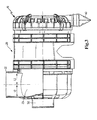
- a passage slot 40 is formed (in Fig. 2 shown dotted).
- the extension has (s. Fig. 3 ) has a first region 41 in which it directly adjoins the flow guide wall 23 and a second region 42 in which the extension 25 terminates at a distance from the flow guide wall 23, so that the passage slot 40 is formed.
- the first region 41 is closer to the axial end region of the filter housing than the second region 42, ie the passage slot 40 is arranged in a section of the extension 25 facing away from the axial end region.
- the distance between extension 25 and flow guide wall 23, so the height of the passage slot 40 is between one and five millimeters.
- the passage slot has a constant height, but it would also be an increasing with increasing distance from the axial end portion of the housing height, ie an increasing distance to the flow guide, conceivable.
- the extension 25 is provided substantially in the half of the inlet nozzle 22, which has a smaller distance 43 (see FIG. Fig. 1 ) to the central axis M of the hollow cylindrical filter housing 20, and thus acts as a barrier or deflector for the forming annular flow 26, thereby promoting the formation of a helical flow.
- the flow guide wall 23 is arranged axially parallel to the central axis M of the hollow cylindrical filter housing 20 and to the cylindrical filter housing wall 21.
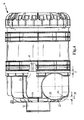
- the Strömungsleitwand 23 axially covers the inlet port 22 (s. Fig. 4 ), ie it protrudes so far into the interior of the filter housing, that through the inlet port entering flow completely enters the annular flow space or meets the Strömungsleitwand.
- the flow guide wall 23 projects beyond the inlet nozzle 22 by the distance d.
- a dust discharge opening for discharging dust by means of a dust discharge valve 60 (see FIG. Fig. 3 ) intended.
- the annular flow space 24 is axially limited by a flat, annular circumferential housing wall portion 29 (s. Fig. 4 ), wherein the cross section of the inlet nozzle 22, the housing wall portion 29 axially by the distance e, directed away from the interior of the filter housing, surmounted.
- a transition region 44 is preferably provided in the inlet region of the inlet nozzle 22, which merges into the annular circumferential housing wall section. In this way, the introduction of a spiral flow can be supported, in particular without having to accept disadvantages in the pressure loss.
- the inlet nozzle 22 has a substantially circular.
- the inlet nozzle is as in Fig. 1 and 2 can be seen preferably as far outside the housing arranged without exceeding the maximum width of the housing.
- the diameter of the inlet nozzle 22 can be made larger than before, so that the ratio of the diameter of the inlet nozzle to the diameter of the filter element is as large as possible.
Landscapes
- Engineering & Computer Science (AREA)
- Chemical & Material Sciences (AREA)
- Chemical Kinetics & Catalysis (AREA)
- Combustion & Propulsion (AREA)
- Mechanical Engineering (AREA)
- General Engineering & Computer Science (AREA)
- Physics & Mathematics (AREA)
- Geometry (AREA)
- Filtering Of Dispersed Particles In Gases (AREA)
Abstract
Description
- Die Erfindung betrifft einen Luftilter, insbesondere für die Ansaugluft von Brennkraftmaschinen, umfassend ein hohlzylindrisches Filtergehäuse und ein Filterelement mit einem ringförmig geschlossenen, insbesondere sternförmig gefalteten Filtermedium.
- Aus der
DE 10 2010 010 964 A1 ist ein Luftfilter bekannt, der einen tangentialen Einlassstutzen aufweist. Die einströmende Luft tritt dort in einen ringförmigen Strömungskanal ein, der ein rundes Filterelement teilweise umgibt. - Die Erfindung hat die Aufgabe den gattungsgemäßen Filter dahingehend zu verbessern, dass der Strömungswiderstand reduziert wird und/oder die Vorabscheidung verbessert wird, ohne mehr Einbauraum als bisher zu benötigen.
- Diese Aufgabe wird überaschender Weise durch einen Luftilter gelöst, umfassend ein hohlzylindrisches Filtergehäuse und ein Filterelement mit einem ringförmig geschlossenen, insbesondere sternförmig gefalteten Filtermedium, wobei das Filtergehäuse an einem ersten axialen Endbereich einen in der zylindrischen Außenwand angeordneten, tangentialen Einlassstutzen und eine ringförmige, koaxial in das Filtergehäuse hineinragende Strömungsleitwand aufweist, die das Filterelement umschließt, wobei ein ringförmiger Strömungsraum zwischen zylindrischer Außenwand und Strömungsleitwand gebildet ist, wobei der Einlassstutzen einen Fortsatz aufweist, der in einem Teilbereich in den ringförmigen Strömungsraum hineinragt und den ringförmigen Strömungsraum bis zur Strömungsleitwand überbrückt.
- Durch den Fortsatz wird erreicht, dass sich im ringförmigen Strömungsraum eine ringförmige, in eine Spiralform übergehende Strömung ausbildet, die gleichmäßiger ist und somit sowohl für eine verbesserte Vorabscheidung durch Fliehkraftwirkung als auch für einen geringeren Druckverlust ausschlaggebend sein kann.
- Tangential bedeutet in Bezug auf den Einlassstutzen, dass dieser nicht radial in Bezug auf die Mittelachse ausgerichtet ist, sondern eine Strömungsrichtung und insbesondere eine zentrale Achse aufweist, die im Wesentlichen tangential zu einer Kreisbahn ausgerichtet ist, die konzentrisch zur Mittelachse des Filtergehäuses verläuft. Die Strömung tritt dabei in einem Eintrittsbereich aus dem Einlassstutzen in das Filtergehäuse über. Bevorzugt ist dabei, dass der Einlassstutzen im äußeren Bereich des Eintrittsbereichs in flachem Winkel und/oder im Wesentlichen tangential in die zylindrische Filtergehäusewand übergeht. Weiter bevorzugt ist, dass der Einlassstutzen materialeinheitlich oder unlösbar verbunden mit der Filtergehäusewand ausgeführt ist.
- In einer Ausführungsform ist zwischen Fortsatz und Strömungsleitwand ein Durchgangsschlitz gebildet. Durch diesen wird erreicht, dass ein Teil der sich im ringförmigen Strömungskanal ausbildenden, ring- oder spiralförmigen Strömung erneut in den Eintrittsbereich des Einlassstutzens in den ringförmigen Strömungskanal eintreten kann, wodurch einerseits der Druckverlust durch Umlenkung am Fortsatz reduziert werden kann. Andererseits ist der Durchgangsschlitz bevorzugt unmittelbar an der Strömungsleitwand angeordnet und damit in dem Bereich, in welchem sich aufgrund der Fliehkraftwirkung am wenigsten Partikel befinden. Dadurch kann insbesondere die Vorabscheideleistung verbessert werden.
- In einer Ausführungsform weist der Fortsatz einen ersten Bereich auf, in welchem er unmittelbar an die Strömungsleitwand angrenzt oder mit dieser materialeinheitlich verbunden ist und einen zweiten Bereich, in welchem der Fortsatz in einem Abstand von der Strömungsleitwand endet, so dass der Durchgangsschlitz gebildet ist. Dabei ist bevorzugt der erste Bereich dem axialen Endbereich des Filtergehäuses näher als der zweite Bereich, d.h. der Durchgangsschlitz ist in einem von dem axialen Endbereich abgewandten Abschnitt des Fortsatzes angeordnet. Auf diese Weise kann eine Optimierung in Bezug auf Umlenkeffekt und Druckverlust erreicht werden. Der Abstand zwischen Fortsatz und Strömungsleitwand, also die Höhe des Durchgangsschlitzes beträgt bevorzugt zwischen einem und 10 Millimetern, besonders bevorzugt zwischen einem und fünf Millimetern. Der Durchgangsschlitz kann eine konstante Höhe aufweisen oder eine mit zunehmendem Abstand vom axialen Endbereich des Gehäuses zunehmende Höhe, d.h. einen steigenden Abstand zur Strömungsleitwand, aufweisen.
- In einer Ausführungsform ist der Fortsatz im Wesentlichen in der Hälfte des Einlassstutzen vorgesehen, der einen geringeren Abstand zur Mittelachse des hohlzylindrischen Filtergehäuses aufweist, und wirkt somit als Sperre oder Ablenkvorrichtung für die sich ausbildende ringförmige Strömung, wodurch die Ausbildung einer spiralförmigen Strömung unterstützt wird.
- In einer Ausführungsform ist die Strömungsleitwand achsparallel zur Mittelachse des hohlzylindrischen Filtergehäuses angeordnet und/oder konzentrisch zur zylindrischen Filtergehäusewand.
- In einer Ausführungsform überdeckt die Strömungsleitwand axial den Einlassstutzen, d.h. sie ragt so weit in den Innenraum des Filtergehäuses hinein, dass die durch den Einlassstutzen eintretende Strömung vollständig in den ringförmigen Strömungsraum eintritt oder auf die Strömungsleitwand trifft. Dadurch kann die Vorabscheidewirkung optimiert und/oder eine ungleichmäßige Beladung des Filterelements vermieden werden.
- In einer Ausführungsform ist im Filtergehäuse im axialen Endbereich ein zentraler Auslassstutzen angeordnet, der mit einem Innenraum des Filterelementes verbunden ist.
- In einer Ausführungsform ist im zweiten axialen Endbereich eine Staubaustragsöffnung zum Staubaustrag mittels einer Absaugung oder eines Staubaustragventils vorgesehen.
- In einer Ausführungsform ist der ringförmige Strömungskanal axial von einem flachen, ringförmig umlaufenden Gehäusewandabschnitt begrenzt, wobei der Querschnitt des Einlassstutzens den Gehäusewandabschnitt axial, vom Innenraum des Filtergehäuses weg gerichtet, überragt. Dabei ist bevorzugt im Eintrittsbereich des Einlassstutzens ein Übergangsbereich vorgesehen, der in den ringförmig umlaufenden Gehäusewandabschnitt übergeht. Auf diese Weise kann die Einleitung einer spiralförmigen Strömung unterstützt werden, insbesondere ohne Nachteile beim Druckverlust in Kauf nehmen zu müssen.
- In einer Ausführungsform weist der Einlassstutzen einen im Wesentlichen kreisförmigen oder ovalen Querschnitt auf.
- In einer Ausführungsform ist der Einlassstutzen möglichst weit außen am Gehäuse angeordnet, ohne die maximale Breite des Gehäuses zu überragen. Somit kann der Durchmesser des Einlassstutzens größer als bisher gestaltet werden, so dass das Verhältnis aus dem Durchmesser des Einlassstutzens zum Durchmesser des Filterelementes möglichst groß ist. Dadurch kann der Strömungswiderstand reduziert werden, wodurch sich zusätzlich die Standzeit des Filterelementes erhöht. Da der Einlassstutzens möglichst weit außen am Gehäuse angeordnet ist, ohne die maximale Breite des Gehäuses zu überragen, kann trotz des vergrößerten Einlassstutzens und des reduzierten Strömungswiderstands der bisher für das Gehäuse erforderliche Einbauraum beibehalten werden. Durch den möglichst weit außen am Gehäuse angeordneten Einlassstutzen kann der Einlassstutzen eine deutlich größere Weite als bisher aufweisen, wodurch der Strömungswiderstand zusätzlich reduziert wird.
- Der Einlassstutzen kann das mindestens eine Filterelement seiner Länge nach teilweise überdecken, so dass die Rohluft am Ende des Zuführkanals in das Filterelement eintreten kann.
- Hinsichtlich einer besonders hohen Filterwirkung kann der Filter ein Primärfilterelement und ein Sekundärfilterelement aufweisen, wobei das Sekundärfilterelement bevorzugt koaxial zum und innerhalb des Primärfilterelements angeordnet ist.
- In einer bevorzugten Ausführungsform kann der Filter für eine Brennkraftmaschine vorgesehen sein.
- Ferner kann der Filter in einer weiteren bevorzugten Ausführungsform für einen mobilen Druckluftkompressor vorgesehen sein.
- Nachfolgend wird der erfindungsgemäße Filter anhand der beiliegenden Zeichnungen näher erläutert.
- Im Einzelnen zeigen:
-
Fig. 1 eine quer zur Mittelachse geschnittene Ansicht auf den Luftfilter, -
Fig. 2 eine perspektivische Ansicht des Filters ausFig. 1 ; -
Fig. 3 eine erste Ansicht mit einem Teilschnitt durch den Filter ausFig. 1 ; -
Fig. 4 eine zweite Ansicht mit einem Teilschnitt durch den Filter ausFig. 1 . -
Fig. 1 zeigt einen Luftilter 10, umfassend ein hohlzylindrisches Filtergehäuse 20 und ein Filterelement 30 mit einem ringförmig geschlossenen, insbesondere sternförmig gefalteten Filtermedium, wobei das Filtergehäuse 20 an einem ersten axialen Endbereich einen in der zylindrischen Außenwand 21 angeordneten, tangentialen Einlassstutzen 22 und eine ringförmige, koaxial in das Filtergehäuse hineinragende Strömungsleitwand 23 aufweist, die das Filterelement 30 umschließt, wobei ein ringförmiger Strömungsraum 24 zwischen zylindrischer Außenwand 21 und Strömungsleitwand 23 gebildet ist, wobei der Einlassstutzen 22 einen Fortsatz 25 aufweist, der in einem Teilbereich in den ringförmigen Strömungsraum 24 hineinragt und den ringförmigen Strömungsraum bis zur Strömungsleitwand 23 überbrückt. - Durch den Fortsatz wird erreicht, dass sich im ringförmigen Strömungsraum 24 eine ringförmige, in eine Spiralform übergehende, durch Pfeile 26 schematisch dargestellte Strömung ausbildet.
- Tangential bedeutet in Bezug auf den Einlassstutzen 22, dass dieser nicht radial in Bezug auf die Mittelachse ausgerichtet ist, sondern eine Strömungsrichtung und insbesondere eine zentrale Achse 28 aufweist, die im Wesentlichen tangential zu einer Kreisbahn 27 ausgerichtet ist, die konzentrisch zur Mittelachse M des Filtergehäuses 20 verläuft. Die Strömung tritt dabei in einem Eintrittsbereich aus dem Einlassstutzen 22 in das Filtergehäuse 20 über. Bevorzugt ist dabei, dass der Einlassstutzen 22 im äußeren Bereich des Eintrittsbereichs in flachem Winkel W und/oder im Wesentlichen tangential in die zylindrische Filtergehäusewand 21 übergeht. Der Einlassstutzen 22 ist materialeinheitlich mit der Filtergehäusewand aus einem Thermoplast, insbesondere mit Glasfaseranteil ausgeführt.
- Zwischen Fortsatz 25 und Strömungsleitwand 23 ein Durchgangsschlitz 40 gebildet (in
Fig. 2 gepunktet dargestellt). Durch diesen wird erreicht, dass ein Teil der sich im ringförmigen Strömungsraum 24 ausbildenden, ring- oder spiralförmigen Strömung 26 erneut in den Eintrittsbereich des Einlassstutzens 22 in den ringförmigen Strömungskanal 23 eintreten kann, wodurch einerseits der Druckverlust durch Umlenkung am Fortsatz 25 reduziert werden kann. Andererseits ist der Durchgangsschlitz 40 bevorzugt unmittelbar an der Strömungsleitwand 23 angeordnet und damit in dem Bereich, in welchem sich aufgrund der Fliehkraftwirkung am wenigsten Partikel befinden. Dadurch kann insbesondere die Vorabscheideleistung verbessert werden. - Der Fortsatz weist (s.
Fig. 3 ) einen ersten Bereich 41 auf, in welchem er unmittelbar an die Strömungsleitwand 23 angrenzt und einen zweiten Bereich 42, in welchem der Fortsatz 25 in einem Abstand von der Strömungsleitwand 23 endet, so dass der Durchgangsschlitz 40 gebildet ist. Dabei ist der erste Bereich 41 dem axialen Endbereich des Filtergehäuses näher als der zweite Bereich 42, d.h. der Durchgangsschlitz 40 ist in einem von dem axialen Endbereich abgewandten Abschnitt des Fortsatzes 25 angeordnet. Der Abstand zwischen Fortsatz 25 und Strömungsleitwand 23, also die Höhe des Durchgangsschlitzes 40 beträgt zwischen einem und fünf Millimetern. Der Durchgangsschlitz weist eine konstante Höhe auf, es wäre jedoch auch eine mit zunehmendem Abstand vom axialen Endbereich des Gehäuses zunehmende Höhe, d.h. einen steigenden Abstand zur Strömungsleitwand, denkbar. - Der Fortsatz 25 ist im Wesentlichen in der Hälfte des Einlassstutzens 22 vorgesehen, der einen geringeren Abstand 43 (s.
Fig. 1 ) zur Mittelachse M des hohlzylindrischen Filtergehäuses 20 aufweist, und wirkt somit als Sperre oder Ablenkvorrichtung für die sich ausbildende ringförmige Strömung 26, wodurch die Ausbildung einer spiralförmigen Strömung unterstützt wird. - Die Strömungsleitwand 23 ist achsparallel zur Mittelachse M des hohlzylindrischen Filtergehäuses 20 und zur zylindrischen Filtergehäusewand 21 angeordnet.
- Die Strömungsleitwand 23 überdeckt axial den Einlassstutzen 22 (s.
Fig. 4 ), d.h. sie ragt so weit in den Innenraum des Filtergehäuses hinein, dass die durch den Einlassstutzen eintretende Strömung vollständig in den ringförmigen Strömungsraum eintritt oder auf die Strömungsleitwand trifft. In der gezeigten Ausführungsform überragt die Strömungsleitwand 23 den Einlassstutzen 22 um die Distanz d. - Ferner ist im Filtergehäuse 20 im axialen Endbereich ein zentraler Auslassstutzen 50 angeordnet, der mit einem Innenraum des Filterelementes verbunden ist.
- Auch ist im zweiten axialen Endbereich eine Staubaustragsöffnung zum Staubaustrag mittels eines Staubaustragventils 60 (s.
Fig. 3 ) vorgesehen. - Der ringförmige Strömungsraum 24 ist axial von einem flachen, ringförmig umlaufenden Gehäusewandabschnitt 29 begrenzt (s.
Fig. 4 ), wobei der Querschnitt des Einlassstutzens 22 den Gehäusewandabschnitt 29 um die Distanz e axial, vom Innenraum des Filtergehäuses weg gerichtet, überragt. Dabei ist bevorzugt im Eintrittsbereich des Einlassstutzens 22 ein Übergangsbereich 44 vorgesehen, der in den ringförmig umlaufenden Gehäusewandabschnitt übergeht. Auf diese Weise kann die Einleitung einer spiralförmigen Strömung unterstützt werden, insbesondere ohne Nachteile beim Druckverlust in Kauf nehmen zu müssen. Der Einlassstutzen 22 weist einen im Wesentlichen kreisförmigen auf. - Der Einlassstutzen ist wie in
Fig. 1 und2 ersichtlich bevorzugt möglichst weit außen am Gehäuse angeordnet, ohne die maximale Breite des Gehäuses zu überragen. Somit kann der Durchmesser des Einlassstutzens 22 größer als bisher gestaltet werden, so dass das Verhältnis aus dem Durchmesser des Einlassstutzens zum Durchmesser des Filterelementes möglichst groß ist.
Claims (10)
- Luftilter, insbesondere für die Ansaugluft von Brennkraftmaschinen, umfassend ein hohlzylindrisches Filtergehäuse und
ein Filterelement mit einem ringförmig geschlossenen, insbesondere sternförmig gefalteten Filtermedium,
wobei das Filtergehäuse an einem ersten axialen Endbereich
einen in der zylindrischen Außenwand angeordneten, tangentialen Einlassstutzen und eine ringförmige, koaxial in das Filtergehäuse hineinragende Strömungsleitwand aufweist, die das Filterelement umschließt, wobei ein ringförmiger Strömungsraum zwischen zylindrischer Außenwand und Strömungsleitwand gebildet ist, dadurch gekennzeichnet, dass der Einlassstutzen einen Fortsatz aufweist, der in einem Teilbereich in den ringförmigen Strömungsraum hineinragt und den ringförmigen Strömungsraum bis zur Strömungsleitwand überbrückt. - Luftfilter nach Anspruch 1, wobei zwischen Fortsatz und Strömungsleitwand ein Durchgangsschlitz gebildet ist.
- Luftfilter nach Anspruch 2, wobei der Fortsatz einen ersten Bereich aufweist, in welchem er unmittelbar an die Strömungsleitwand angrenzt oder mit dieser materialeinheitlich verbunden ist und einen zweiten Bereich aufweist, in welchem der Fortsatz in einem Abstand zwischen einem und 10 Millimetern, bevorzugt zwischen einem und fünf Millimetern von der Strömungsleitwand endet, so dass der Durchgangsschlitz gebildet ist.
- Luftfilter nach Anspruch 2 oder 3, wobei der Durchgangsschlitz in einem von dem axialen Endbereich abgewandten Abschnitt des Fortsatzes angeordnet ist.
- Luftfilter nach einem der vorhergehenden Ansprüche, wobei der Fortsatz im Wesentlichen in der Hälfte des Einlassstutzens vorgesehen ist, der einen geringeren Abstand zur Mittelachse des hohlzylindrischen Filtergehäuses aufweist.
- Luftfilter nach einem der vorhergehenden Ansprüche, wobei die Strömungsleitwand achsparallel zur Mittelachse des hohlzylindrischen Filtergehäuses angeordnet ist.
- Luftfilter nach einem der vorhergehenden Ansprüche, wobei die Strömungsleitwand axial den Einlassstutzen überdeckt.
- Luftfilter nach einem der vorhergehenden Ansprüche, wobei im Filtergehäuse im axialen Endbereich ein zentraler Auslassstutzen angeordnet ist, der mit einem Innenraum des Filterelementes verbunden ist.
- Luftfilter nach einem der vorhergehenden Ansprüche, wobei im zweiten axialen Endbereich eine Staubaustragsöffnung zum Staubaustrag mittels einer Absaugung oder eines Staubaustragventils vorgesehen ist.
- Luftfilter nach einem der vorhergehenden Ansprüche, wobei der ringförmige Strömungskanal axial von einem flachen, ringförmig umlaufenden Gehäusewandabschnitt begrenzt ist und der Querschnitt des Einlassstutzens den Gehäusewandabschnitt axial überragt.
Applications Claiming Priority (1)
| Application Number | Priority Date | Filing Date | Title |
|---|---|---|---|
| DE102012020574.0A DE102012020574A1 (de) | 2012-10-22 | 2012-10-22 | Filter |
Publications (2)
| Publication Number | Publication Date |
|---|---|
| EP2722091A1 true EP2722091A1 (de) | 2014-04-23 |
| EP2722091B1 EP2722091B1 (de) | 2016-08-24 |
Family
ID=49385116
Family Applications (1)
| Application Number | Title | Priority Date | Filing Date |
|---|---|---|---|
| EP13188714.3A Active EP2722091B1 (de) | 2012-10-22 | 2013-10-15 | Filter |
Country Status (4)
| Country | Link |
|---|---|
| US (1) | US9212636B2 (de) |
| EP (1) | EP2722091B1 (de) |
| CN (1) | CN103775260B (de) |
| DE (1) | DE102012020574A1 (de) |
Cited By (2)
| Publication number | Priority date | Publication date | Assignee | Title |
|---|---|---|---|---|
| US20210031130A1 (en) * | 2014-12-19 | 2021-02-04 | Cummins Filtration Ip, Inc. | Pre-Cleaning Air Filter |
| US12172116B2 (en) | 2018-10-23 | 2024-12-24 | Cummins Filtration Ip, Inc. | Air filter assembly with a permeable baffle |
Families Citing this family (6)
| Publication number | Priority date | Publication date | Assignee | Title |
|---|---|---|---|---|
| US10737282B2 (en) * | 2015-10-12 | 2020-08-11 | Cummins Filtration Ip, Inc. | Tangential air cleaner with coiled filter cartridge |
| AU2016353054B2 (en) | 2015-11-10 | 2019-07-25 | Techtronic Industries Co. Ltd. | Handheld vacuum cleaner |
| DE102018001183A1 (de) * | 2017-04-21 | 2018-10-25 | Mann+Hummel Gmbh | Luftfilter mit geringem Druckverlust |
| CN107167560A (zh) * | 2017-06-19 | 2017-09-15 | 亿信标准认证集团四川有限公司 | 避免苯酚影响甲醛含量测定的接头 |
| EP3623033A1 (de) * | 2018-09-13 | 2020-03-18 | Primetals Technologies Austria GmbH | Vorrichtung zur entstaubung von konvertergas |
| CN118577037B (zh) * | 2024-06-12 | 2026-07-21 | 黄鹄(浙江)精密机床有限公司 | 一种加工机床处理用固液分离装置 |
Citations (4)
| Publication number | Priority date | Publication date | Assignee | Title |
|---|---|---|---|---|
| GB1185233A (en) * | 1967-09-09 | 1970-03-25 | Burgess Products Co Ltd | Dry Air Filters |
| DE2308840A1 (de) * | 1972-02-22 | 1973-08-30 | Burgess Products Co Ltd | Lufttrockenfilter |
| US6958083B1 (en) * | 2004-01-15 | 2005-10-25 | Fleetguard, Inc. | Air cleaner with reduced restriction precleaner |
| DE102010010964A1 (de) | 2010-03-10 | 2011-09-15 | Mann + Hummel Gmbh | Filterelement zur Fluidfiltration, insbesondere für Ansaugluft von Brennkraftmaschinen |
Family Cites Families (17)
| Publication number | Priority date | Publication date | Assignee | Title |
|---|---|---|---|---|
| FR1379165A (fr) * | 1963-12-05 | 1964-11-20 | Raymond Proust Ets | Filtre pour fluide |
| US3429108A (en) * | 1967-03-03 | 1969-02-25 | Donaldson Co Inc | Automatic-unloading dust valve for centrifugal air cleaners |
| US4491460A (en) * | 1983-01-31 | 1985-01-01 | Donaldson Company, Inc. | Air cleaner and deflecting intake tube |
| US5545241B1 (en) * | 1995-01-17 | 1999-09-28 | Donaldson Co Inc | Air cleaner |
| DE19913181A1 (de) * | 1999-03-24 | 2000-09-28 | Mann & Hummel Filter | Filter mit topfförmigem Gehäuse und Rundfilterpatrone |
| DE602005019417D1 (de) * | 2004-07-20 | 2010-04-01 | Donaldson Co Inc | Z-filtermedienpackungsanordnung, filterpatrone, luftreinigungsvorrichtungsanordnung und verfahren |
| ES2358433T3 (es) * | 2004-08-25 | 2011-05-10 | Donaldson Company, Inc. | Filtro de aire y cartuchos filtrantes intercambiables. |
| JP4462236B2 (ja) * | 2006-06-08 | 2010-05-12 | トヨタ自動車株式会社 | 気体濾過装置 |
| DE202006011990U1 (de) * | 2006-08-03 | 2007-12-20 | Mann + Hummel Gmbh | Filtereinheit mit einem radial geteilten Gehäuse |
| US8066791B2 (en) * | 2007-07-20 | 2011-11-29 | Donaldson Company, Inc. | Air cleaner arrangements with internal and external support for cartridge; components; and, methods |
| DE202009003669U1 (de) * | 2009-03-17 | 2010-08-12 | Mann+Hummel Gmbh | Filterelement |
| US8409317B2 (en) * | 2009-10-13 | 2013-04-02 | Cummins Filtration Ip Inc. | Filter assembly with housing structure |
| DE112011103121B4 (de) * | 2010-09-16 | 2023-12-07 | Cummins Filtration Ip, Inc. | Austauschbares luftfilterelement und luftfilterbaugruppe |
| DE102011120387B4 (de) * | 2010-12-15 | 2015-05-28 | Mann + Hummel Gmbh | Luftfilteranordnung und Filtervorrichtung mit einer Luftfilteranordnung |
| DE102010055386A1 (de) * | 2010-12-21 | 2012-06-21 | Solo Kleinmotoren Gmbh | Airbox mit zwei Ansaugkanälen |
| CN202017561U (zh) * | 2010-12-23 | 2011-10-26 | 杨松有 | 汽车空气过滤器 |
| CN201908754U (zh) * | 2011-01-21 | 2011-07-27 | 合肥亿利汽车零部件有限公司 | 带偏置进气口空滤器 |
-
2012
- 2012-10-22 DE DE102012020574.0A patent/DE102012020574A1/de not_active Ceased
-
2013
- 2013-10-15 EP EP13188714.3A patent/EP2722091B1/de active Active
- 2013-10-21 US US14/058,932 patent/US9212636B2/en active Active
- 2013-10-22 CN CN201310525666.4A patent/CN103775260B/zh active Active
Patent Citations (4)
| Publication number | Priority date | Publication date | Assignee | Title |
|---|---|---|---|---|
| GB1185233A (en) * | 1967-09-09 | 1970-03-25 | Burgess Products Co Ltd | Dry Air Filters |
| DE2308840A1 (de) * | 1972-02-22 | 1973-08-30 | Burgess Products Co Ltd | Lufttrockenfilter |
| US6958083B1 (en) * | 2004-01-15 | 2005-10-25 | Fleetguard, Inc. | Air cleaner with reduced restriction precleaner |
| DE102010010964A1 (de) | 2010-03-10 | 2011-09-15 | Mann + Hummel Gmbh | Filterelement zur Fluidfiltration, insbesondere für Ansaugluft von Brennkraftmaschinen |
Cited By (3)
| Publication number | Priority date | Publication date | Assignee | Title |
|---|---|---|---|---|
| US20210031130A1 (en) * | 2014-12-19 | 2021-02-04 | Cummins Filtration Ip, Inc. | Pre-Cleaning Air Filter |
| US12076676B2 (en) * | 2014-12-19 | 2024-09-03 | Cummins Filtration Ip, Inc. | Pre-cleaning air filter |
| US12172116B2 (en) | 2018-10-23 | 2024-12-24 | Cummins Filtration Ip, Inc. | Air filter assembly with a permeable baffle |
Also Published As
| Publication number | Publication date |
|---|---|
| DE102012020574A1 (de) | 2014-04-24 |
| CN103775260B (zh) | 2017-12-12 |
| CN103775260A (zh) | 2014-05-07 |
| US9212636B2 (en) | 2015-12-15 |
| US20140109532A1 (en) | 2014-04-24 |
| EP2722091B1 (de) | 2016-08-24 |
Similar Documents
| Publication | Publication Date | Title |
|---|---|---|
| EP2722091B1 (de) | Filter | |
| DE112012005379B4 (de) | Fliehkraftabscheider und Filteranordnung | |
| EP2532408B2 (de) | Luftfilter mit vorabscheider | |
| DE102015006497B4 (de) | Zyklonabscheider sowie Filtervorrichtung mit Zyklonabscheider | |
| DE112012005362B4 (de) | Fliehkraftabscheider und Filteranordnung | |
| EP2129445B1 (de) | Filter zur reinigung eines fluids | |
| DE102013015052B4 (de) | Zyklon-Filtereinrichtung | |
| EP2069042B1 (de) | Vorrichtung zum abscheiden von partikeln aus einem gasstrom | |
| WO2009068181A1 (de) | Turbolader | |
| EP3323492A1 (de) | Filter und zyklonfiltersystem | |
| DE102011121996A1 (de) | Vorrichtung zum Betrieb eines Verdichters | |
| WO2011045225A1 (de) | Filtervorrichtung und hauptfilterelement für eine filtervorrichtung | |
| DE102015008525A1 (de) | Fliehkraftabscheider und Filteranordnung | |
| WO2016150769A1 (de) | Mischvorrichtung | |
| DE102004035688A1 (de) | Vorrichtung zur Trennung von Partikeln aus einem Medienstrom | |
| DE102014226298A1 (de) | Gebläse | |
| WO2010130430A1 (de) | Filter | |
| EP1364696A1 (de) | Vorrichtung zur Reinigung eines Gasstromes | |
| WO2008006475A1 (de) | Luftfilteranordnung für ein kraftfahrzeug | |
| WO2013083452A1 (de) | Abscheidevorrichtung mit zwei zyklonzellen | |
| DE102016004497B4 (de) | Abscheidevorrichtung sowie Anordnung zur Reinigung einer Ansaugluft einer Brennkraftmaschine | |
| DE102008021729A1 (de) | Ölabscheidevorrichtung, insbesondere für die Druckluftentölung eines Verdichters | |
| DE202006019819U1 (de) | Vorabscheider | |
| WO2004041411A1 (de) | Vorrichtung zum abscheiden von partikeln aus einem gasstrom | |
| EP3101248B1 (de) | Abgasstrang für eine brennkraftmaschine |
Legal Events
| Date | Code | Title | Description |
|---|---|---|---|
| PUAI | Public reference made under article 153(3) epc to a published international application that has entered the european phase |
Free format text: ORIGINAL CODE: 0009012 |
|
| AK | Designated contracting states |
Kind code of ref document: A1 Designated state(s): AL AT BE BG CH CY CZ DE DK EE ES FI FR GB GR HR HU IE IS IT LI LT LU LV MC MK MT NL NO PL PT RO RS SE SI SK SM TR |
|
| AX | Request for extension of the european patent |
Extension state: BA ME |
|
| 17P | Request for examination filed |
Effective date: 20140506 |
|
| RBV | Designated contracting states (corrected) |
Designated state(s): AL AT BE BG CH CY CZ DE DK EE ES FI FR GB GR HR HU IE IS IT LI LT LU LV MC MK MT NL NO PL PT RO RS SE SI SK SM TR |
|
| GRAP | Despatch of communication of intention to grant a patent |
Free format text: ORIGINAL CODE: EPIDOSNIGR1 |
|
| INTG | Intention to grant announced |
Effective date: 20160415 |
|
| GRAS | Grant fee paid |
Free format text: ORIGINAL CODE: EPIDOSNIGR3 |
|
| GRAA | (expected) grant |
Free format text: ORIGINAL CODE: 0009210 |
|
| AK | Designated contracting states |
Kind code of ref document: B1 Designated state(s): AL AT BE BG CH CY CZ DE DK EE ES FI FR GB GR HR HU IE IS IT LI LT LU LV MC MK MT NL NO PL PT RO RS SE SI SK SM TR |
|
| REG | Reference to a national code |
Ref country code: GB Ref legal event code: FG4D Free format text: NOT ENGLISH |
|
| REG | Reference to a national code |
Ref country code: CH Ref legal event code: EP |
|
| REG | Reference to a national code |
Ref country code: AT Ref legal event code: REF Ref document number: 822561 Country of ref document: AT Kind code of ref document: T Effective date: 20160915 |
|
| REG | Reference to a national code |
Ref country code: IE Ref legal event code: FG4D Free format text: LANGUAGE OF EP DOCUMENT: GERMAN |
|
| REG | Reference to a national code |
Ref country code: DE Ref legal event code: R096 Ref document number: 502013004137 Country of ref document: DE |
|
| REG | Reference to a national code |
Ref country code: LT Ref legal event code: MG4D |
|
| REG | Reference to a national code |
Ref country code: NL Ref legal event code: MP Effective date: 20160824 |
|
| PG25 | Lapsed in a contracting state [announced via postgrant information from national office to epo] |
Ref country code: IT Free format text: LAPSE BECAUSE OF FAILURE TO SUBMIT A TRANSLATION OF THE DESCRIPTION OR TO PAY THE FEE WITHIN THE PRESCRIBED TIME-LIMIT Effective date: 20160824 Ref country code: LT Free format text: LAPSE BECAUSE OF FAILURE TO SUBMIT A TRANSLATION OF THE DESCRIPTION OR TO PAY THE FEE WITHIN THE PRESCRIBED TIME-LIMIT Effective date: 20160824 Ref country code: RS Free format text: LAPSE BECAUSE OF FAILURE TO SUBMIT A TRANSLATION OF THE DESCRIPTION OR TO PAY THE FEE WITHIN THE PRESCRIBED TIME-LIMIT Effective date: 20160824 Ref country code: NL Free format text: LAPSE BECAUSE OF FAILURE TO SUBMIT A TRANSLATION OF THE DESCRIPTION OR TO PAY THE FEE WITHIN THE PRESCRIBED TIME-LIMIT Effective date: 20160824 Ref country code: HR Free format text: LAPSE BECAUSE OF FAILURE TO SUBMIT A TRANSLATION OF THE DESCRIPTION OR TO PAY THE FEE WITHIN THE PRESCRIBED TIME-LIMIT Effective date: 20160824 Ref country code: FI Free format text: LAPSE BECAUSE OF FAILURE TO SUBMIT A TRANSLATION OF THE DESCRIPTION OR TO PAY THE FEE WITHIN THE PRESCRIBED TIME-LIMIT Effective date: 20160824 Ref country code: NO Free format text: LAPSE BECAUSE OF FAILURE TO SUBMIT A TRANSLATION OF THE DESCRIPTION OR TO PAY THE FEE WITHIN THE PRESCRIBED TIME-LIMIT Effective date: 20161124 |
|
| PG25 | Lapsed in a contracting state [announced via postgrant information from national office to epo] |
Ref country code: SE Free format text: LAPSE BECAUSE OF FAILURE TO SUBMIT A TRANSLATION OF THE DESCRIPTION OR TO PAY THE FEE WITHIN THE PRESCRIBED TIME-LIMIT Effective date: 20160824 Ref country code: PT Free format text: LAPSE BECAUSE OF FAILURE TO SUBMIT A TRANSLATION OF THE DESCRIPTION OR TO PAY THE FEE WITHIN THE PRESCRIBED TIME-LIMIT Effective date: 20161226 Ref country code: LV Free format text: LAPSE BECAUSE OF FAILURE TO SUBMIT A TRANSLATION OF THE DESCRIPTION OR TO PAY THE FEE WITHIN THE PRESCRIBED TIME-LIMIT Effective date: 20160824 Ref country code: ES Free format text: LAPSE BECAUSE OF FAILURE TO SUBMIT A TRANSLATION OF THE DESCRIPTION OR TO PAY THE FEE WITHIN THE PRESCRIBED TIME-LIMIT Effective date: 20160824 Ref country code: BE Free format text: LAPSE BECAUSE OF NON-PAYMENT OF DUE FEES Effective date: 20161031 Ref country code: GR Free format text: LAPSE BECAUSE OF FAILURE TO SUBMIT A TRANSLATION OF THE DESCRIPTION OR TO PAY THE FEE WITHIN THE PRESCRIBED TIME-LIMIT Effective date: 20161125 |
|
| PG25 | Lapsed in a contracting state [announced via postgrant information from national office to epo] |
Ref country code: EE Free format text: LAPSE BECAUSE OF FAILURE TO SUBMIT A TRANSLATION OF THE DESCRIPTION OR TO PAY THE FEE WITHIN THE PRESCRIBED TIME-LIMIT Effective date: 20160824 Ref country code: RO Free format text: LAPSE BECAUSE OF FAILURE TO SUBMIT A TRANSLATION OF THE DESCRIPTION OR TO PAY THE FEE WITHIN THE PRESCRIBED TIME-LIMIT Effective date: 20160824 |
|
| REG | Reference to a national code |
Ref country code: DE Ref legal event code: R097 Ref document number: 502013004137 Country of ref document: DE |
|
| PG25 | Lapsed in a contracting state [announced via postgrant information from national office to epo] |
Ref country code: CZ Free format text: LAPSE BECAUSE OF FAILURE TO SUBMIT A TRANSLATION OF THE DESCRIPTION OR TO PAY THE FEE WITHIN THE PRESCRIBED TIME-LIMIT Effective date: 20160824 Ref country code: BG Free format text: LAPSE BECAUSE OF FAILURE TO SUBMIT A TRANSLATION OF THE DESCRIPTION OR TO PAY THE FEE WITHIN THE PRESCRIBED TIME-LIMIT Effective date: 20161124 Ref country code: SM Free format text: LAPSE BECAUSE OF FAILURE TO SUBMIT A TRANSLATION OF THE DESCRIPTION OR TO PAY THE FEE WITHIN THE PRESCRIBED TIME-LIMIT Effective date: 20160824 Ref country code: PL Free format text: LAPSE BECAUSE OF FAILURE TO SUBMIT A TRANSLATION OF THE DESCRIPTION OR TO PAY THE FEE WITHIN THE PRESCRIBED TIME-LIMIT Effective date: 20160824 Ref country code: DK Free format text: LAPSE BECAUSE OF FAILURE TO SUBMIT A TRANSLATION OF THE DESCRIPTION OR TO PAY THE FEE WITHIN THE PRESCRIBED TIME-LIMIT Effective date: 20160824 Ref country code: SK Free format text: LAPSE BECAUSE OF FAILURE TO SUBMIT A TRANSLATION OF THE DESCRIPTION OR TO PAY THE FEE WITHIN THE PRESCRIBED TIME-LIMIT Effective date: 20160824 |
|
| REG | Reference to a national code |
Ref country code: CH Ref legal event code: PL |
|
| PLBE | No opposition filed within time limit |
Free format text: ORIGINAL CODE: 0009261 |
|
| STAA | Information on the status of an ep patent application or granted ep patent |
Free format text: STATUS: NO OPPOSITION FILED WITHIN TIME LIMIT |
|
| REG | Reference to a national code |
Ref country code: IE Ref legal event code: MM4A |
|
| REG | Reference to a national code |
Ref country code: FR Ref legal event code: ST Effective date: 20170630 |
|
| PG25 | Lapsed in a contracting state [announced via postgrant information from national office to epo] |
Ref country code: FR Free format text: LAPSE BECAUSE OF NON-PAYMENT OF DUE FEES Effective date: 20161102 Ref country code: CH Free format text: LAPSE BECAUSE OF NON-PAYMENT OF DUE FEES Effective date: 20161031 Ref country code: LI Free format text: LAPSE BECAUSE OF NON-PAYMENT OF DUE FEES Effective date: 20161031 |
|
| 26N | No opposition filed |
Effective date: 20170526 |
|
| PG25 | Lapsed in a contracting state [announced via postgrant information from national office to epo] |
Ref country code: SI Free format text: LAPSE BECAUSE OF FAILURE TO SUBMIT A TRANSLATION OF THE DESCRIPTION OR TO PAY THE FEE WITHIN THE PRESCRIBED TIME-LIMIT Effective date: 20160824 Ref country code: LU Free format text: LAPSE BECAUSE OF NON-PAYMENT OF DUE FEES Effective date: 20161015 |
|
| PG25 | Lapsed in a contracting state [announced via postgrant information from national office to epo] |
Ref country code: IE Free format text: LAPSE BECAUSE OF NON-PAYMENT OF DUE FEES Effective date: 20161015 |
|
| REG | Reference to a national code |
Ref country code: BE Ref legal event code: MM Effective date: 20161031 |
|
| PG25 | Lapsed in a contracting state [announced via postgrant information from national office to epo] |
Ref country code: CY Free format text: LAPSE BECAUSE OF FAILURE TO SUBMIT A TRANSLATION OF THE DESCRIPTION OR TO PAY THE FEE WITHIN THE PRESCRIBED TIME-LIMIT Effective date: 20160824 Ref country code: HU Free format text: LAPSE BECAUSE OF FAILURE TO SUBMIT A TRANSLATION OF THE DESCRIPTION OR TO PAY THE FEE WITHIN THE PRESCRIBED TIME-LIMIT; INVALID AB INITIO Effective date: 20131015 |
|
| GBPC | Gb: european patent ceased through non-payment of renewal fee |
Effective date: 20171015 |
|
| PG25 | Lapsed in a contracting state [announced via postgrant information from national office to epo] |
Ref country code: MC Free format text: LAPSE BECAUSE OF FAILURE TO SUBMIT A TRANSLATION OF THE DESCRIPTION OR TO PAY THE FEE WITHIN THE PRESCRIBED TIME-LIMIT Effective date: 20160824 Ref country code: MT Free format text: LAPSE BECAUSE OF FAILURE TO SUBMIT A TRANSLATION OF THE DESCRIPTION OR TO PAY THE FEE WITHIN THE PRESCRIBED TIME-LIMIT Effective date: 20160824 Ref country code: MK Free format text: LAPSE BECAUSE OF FAILURE TO SUBMIT A TRANSLATION OF THE DESCRIPTION OR TO PAY THE FEE WITHIN THE PRESCRIBED TIME-LIMIT Effective date: 20160824 Ref country code: IS Free format text: LAPSE BECAUSE OF FAILURE TO SUBMIT A TRANSLATION OF THE DESCRIPTION OR TO PAY THE FEE WITHIN THE PRESCRIBED TIME-LIMIT Effective date: 20160824 |
|
| REG | Reference to a national code |
Ref country code: DE Ref legal event code: R081 Ref document number: 502013004137 Country of ref document: DE Owner name: MANN+HUMMEL GMBH, DE Free format text: FORMER OWNER: MANN+HUMMEL GMBH, 71638 LUDWIGSBURG, DE |
|
| PG25 | Lapsed in a contracting state [announced via postgrant information from national office to epo] |
Ref country code: GB Free format text: LAPSE BECAUSE OF NON-PAYMENT OF DUE FEES Effective date: 20171015 |
|
| PG25 | Lapsed in a contracting state [announced via postgrant information from national office to epo] |
Ref country code: TR Free format text: LAPSE BECAUSE OF FAILURE TO SUBMIT A TRANSLATION OF THE DESCRIPTION OR TO PAY THE FEE WITHIN THE PRESCRIBED TIME-LIMIT Effective date: 20160824 Ref country code: AL Free format text: LAPSE BECAUSE OF FAILURE TO SUBMIT A TRANSLATION OF THE DESCRIPTION OR TO PAY THE FEE WITHIN THE PRESCRIBED TIME-LIMIT Effective date: 20160824 |
|
| REG | Reference to a national code |
Ref country code: AT Ref legal event code: MM01 Ref document number: 822561 Country of ref document: AT Kind code of ref document: T Effective date: 20181015 |
|
| PG25 | Lapsed in a contracting state [announced via postgrant information from national office to epo] |
Ref country code: AT Free format text: LAPSE BECAUSE OF NON-PAYMENT OF DUE FEES Effective date: 20181015 |
|
| P01 | Opt-out of the competence of the unified patent court (upc) registered |
Effective date: 20230803 |
|
| PGFP | Annual fee paid to national office [announced via postgrant information from national office to epo] |
Ref country code: DE Payment date: 20251021 Year of fee payment: 13 |