EP2722063B1 - Manuelle Brustpumpe mit Stimulationsmöglichkeit - Google Patents
Manuelle Brustpumpe mit Stimulationsmöglichkeit Download PDFInfo
- Publication number
- EP2722063B1 EP2722063B1 EP13192416.9A EP13192416A EP2722063B1 EP 2722063 B1 EP2722063 B1 EP 2722063B1 EP 13192416 A EP13192416 A EP 13192416A EP 2722063 B1 EP2722063 B1 EP 2722063B1
- Authority
- EP
- European Patent Office
- Prior art keywords
- breastpump
- shield
- milk
- ejection
- pressure
- Prior art date
- Legal status (The legal status is an assumption and is not a legal conclusion. Google has not performed a legal analysis and makes no representation as to the accuracy of the status listed.)
- Expired - Lifetime
Links
Images

Classifications
-
- A—HUMAN NECESSITIES
- A61—MEDICAL OR VETERINARY SCIENCE; HYGIENE
- A61M—DEVICES FOR INTRODUCING MEDIA INTO, OR ONTO, THE BODY; DEVICES FOR TRANSDUCING BODY MEDIA OR FOR TAKING MEDIA FROM THE BODY; DEVICES FOR PRODUCING OR ENDING SLEEP OR STUPOR
- A61M1/00—Suction or pumping devices for medical purposes; Devices for carrying-off, for treatment of, or for carrying-over, body-liquids; Drainage systems
- A61M1/06—Milking pumps
- A61M1/069—Means for improving milking yield
- A61M1/0693—Means for improving milking yield with programmable or pre-programmed sucking patterns
- A61M1/06935—Means for improving milking yield with programmable or pre-programmed sucking patterns imitating the suckling of an infant
-
- A—HUMAN NECESSITIES
- A61—MEDICAL OR VETERINARY SCIENCE; HYGIENE
- A61M—DEVICES FOR INTRODUCING MEDIA INTO, OR ONTO, THE BODY; DEVICES FOR TRANSDUCING BODY MEDIA OR FOR TAKING MEDIA FROM THE BODY; DEVICES FOR PRODUCING OR ENDING SLEEP OR STUPOR
- A61M1/00—Suction or pumping devices for medical purposes; Devices for carrying-off, for treatment of, or for carrying-over, body-liquids; Drainage systems
- A61M1/06—Milking pumps
- A61M1/069—Means for improving milking yield
- A61M1/0697—Means for improving milking yield having means for massaging the breast
-
- A—HUMAN NECESSITIES
- A61—MEDICAL OR VETERINARY SCIENCE; HYGIENE
- A61M—DEVICES FOR INTRODUCING MEDIA INTO, OR ONTO, THE BODY; DEVICES FOR TRANSDUCING BODY MEDIA OR FOR TAKING MEDIA FROM THE BODY; DEVICES FOR PRODUCING OR ENDING SLEEP OR STUPOR
- A61M1/00—Suction or pumping devices for medical purposes; Devices for carrying-off, for treatment of, or for carrying-over, body-liquids; Drainage systems
- A61M1/71—Suction drainage systems
- A61M1/74—Suction control
- A61M1/75—Intermittent or pulsating suction
-
- A—HUMAN NECESSITIES
- A61—MEDICAL OR VETERINARY SCIENCE; HYGIENE
- A61M—DEVICES FOR INTRODUCING MEDIA INTO, OR ONTO, THE BODY; DEVICES FOR TRANSDUCING BODY MEDIA OR FOR TAKING MEDIA FROM THE BODY; DEVICES FOR PRODUCING OR ENDING SLEEP OR STUPOR
- A61M1/00—Suction or pumping devices for medical purposes; Devices for carrying-off, for treatment of, or for carrying-over, body-liquids; Drainage systems
- A61M1/80—Suction pumps
- A61M1/82—Membrane pumps, e.g. bulbs
-
- A—HUMAN NECESSITIES
- A61—MEDICAL OR VETERINARY SCIENCE; HYGIENE
- A61M—DEVICES FOR INTRODUCING MEDIA INTO, OR ONTO, THE BODY; DEVICES FOR TRANSDUCING BODY MEDIA OR FOR TAKING MEDIA FROM THE BODY; DEVICES FOR PRODUCING OR ENDING SLEEP OR STUPOR
- A61M2205/00—General characteristics of the apparatus
- A61M2205/07—General characteristics of the apparatus having air pumping means
- A61M2205/071—General characteristics of the apparatus having air pumping means hand operated
- A61M2205/075—Bulb type
Definitions
- the present invention relates to a breastpump.
- One aspect of the invention further includes a feature to stimulate a milk ejection reflex.
- a prior art device is described e.g. in WO01/34226A1 .
- Breastpumps for the purpose of extracting breastmilk from a nursing mother are well-known and generally comprise: a breastshield (also known as a shield) that is typically funnel-shaped and fits over the breast; a vacuum source connected to the breastshield for generating an intermittent vacuum within the breastshield such that milk is expressed from the breast; and a conduit structure for communicating milk from the breastshield to a receptacle for the expressed milk, as well as for communicating pressure variations (such as the foregoing vacuum) to the breastshield.
- a breastshield also known as a shield
- a vacuum source connected to the breastshield for generating an intermittent vacuum within the breastshield such that milk is expressed from the breast
- a conduit structure for communicating milk from the breastshield to a receptacle for the expressed milk, as well as for communicating pressure variations (such as the foregoing vacuum) to the breastshield.
- U.S. Patent 4,263,912 shows a double bulb configuration, wherein a first squeeze bulb provides a constrictive force to the nipple while a second squeeze bulb applies a suction force to the nipple.
- existing manual breastpumps are not made to differentiate between different phases of the milk expression process, or equipped with a mechanism or method of operation to accommodate the different phases. That process includes, for example, a period before breastfeeding, referred to as the milk ejection period, or "letdown", in which effective removal of the milk from the breast is initiated by the suckling action of a baby's mouth and jaw to produce or stimulate an ejection reflex, in which stored milk is released and made available for expression.
- the milk ejection reflex is the neurohormonal reflex resulting from the tactile stimulation of the nipple sending neuronal impulses to the hypothalamus, and the neurohypophysial release of oxytocin into the systemic circulation.
- the subsequent contraction of the myoepithelial cells within the breast caused by oxytocin moves milk from the alveoli into the collecting ducts and forward to the nipple.
- Milk ejection, or the milk ejection period is the interval when an increased availability of milk from the nipple is caused as a result of the stimulation of the milk ejection reflex. Milk ejection in women normally lasts for approximately two minutes.
- the ejection reflex will be identified in the following also as "ejection".
- the level of pressure applied and the intermittency of the stimulation for initiating ejection are different than the level and intermittency of the action for actually expressing the breast milk.
- Conventional manual breastpumps do not provide a method or mechanism by which a user can easily stimulate an ejection reflex and subsequently commence to efficiently express breastmilk.
- the present invention satisfies these demands, and others.
- One broad aspect of the present invention provides a manual breastpump with a pump mechanism that operates in a mode to promote ejection.
- Another broad aspect of the invention is a truly novel pumping mechanism for one-handed operation of a manual breastpump.
- a pump mechanism includes a single set of elements that may be operated so as to produce both ejection and general pumping.
- the pump mechanism may include generally two sets of elements, each of which is designed so as to produce one of the modes of operation.
- An object of one embodiment of the invention is to provide a handle of the breastpump with the operative mechanism built therein to produce a negative pressure or vacuum for conveyance to the shield of the assembly and application to a woman's breast.
- One more particular application of the object is an expansible chamber, e.g., a dome-like pocket, which is formed in the handle and is compressed and expanded by movement of the handle.
- the term handle contemplates any structure associated with the manual breast pump that is adapted to be manipulated by one or more hand of a user in operation of the pump mechanism.
- a manual breastpump assembly that includes a shield having an interior receiving surface, sized and shaped to receive a woman's nipple and at least some adjacent breast.
- a conduit structure extends to the shield.
- the conduit structure is in communication with the interior of the shield, whereas the conduit conveys air pressure changes to the interior of the shield and also conveys milk expressed from the breast.
- a pump mechanism is connected to the conduit structure.
- the connection of the pump mechanism is releasable.
- the pump mechanism includes a handle portion and an expansible portion connected to the handle defining a vacuum chamber.
- the vacuum chamber is in communication with the shield, as by the conduit structure.
- the pump mechanism operably changes a volume of the vacuum chamber when manipulated by a user.
- the pump mechanism may be operative in a first mode of operation for producing a first change in the volume and a second mode of operation for producing a second change in the volume.
- the first change is greater than the second change.
- One of these pressures can be adapted as the novel letdown feature.
- movement of one part of the handle, such as a distal end (relative to the shield) produces one pressure.
- Movement of the other part of the handle, such as the proximal end produces the other pressure.
- the first and second change in volume is not different.
- a manual breastpump including a shield having an interior shield surface defining an interior.
- a base is provided to which the shield is mounted.
- a conduit structure is formed within the base including a conduit surface defining a conduit to channel milk expressed into the shield.
- a pressure chamber is defined at least in part by an interior sidewall structure of the base.
- the pressure chamber defines a chamber volume and has a chamber axis.
- a movable member is sealably mounted to the interior sidewall structure and is movable to change the chamber volume to produce a pressure change.
- An outlet is formed in the conduit structure through which the pressure change is communicated. The outlet communicates with the shield interior.
- a lever is directly connected to the movable member and is adapted for manipulation by a user's hand.
- the lever is operative in a first mode of operation and a second mode of operation.
- a pivot point is provided for the lever and is located radially from the chamber axis. The lever, when moved relative to the pivot point, causes the movable member to produce a change in volume by alternately increasing and decreasing the volume. The change in volume is relatively less when the lever is operated in the second mode of operation compared to the first mode of operation.
- Another aspect of the invention provides an improved manual breastpump having an expression mechanism generating a primary vacuum for applying an intermittent pulling force upon a portion of a woman's breast placed within a shield for general pumping, wherein the improvement includes a manually operated ejection mechanism generating a secondary vacuum that is communicated to the shield.
- the secondary vacuum is of lesser absolute value in terms of pressure change communicated to the shield than the primary vacuum.
- the secondary vacuum ejection mechanism is preferably designed to enable rapid or staccato-like manipulative pressure pulses on the nipple/breast.
- a manual breastpump assembly including a shield with an interior receiving surface defining a shield interior within which at least a portion of a woman's breast is received.
- the shield is mounted to a shield base.
- a conduit structure is formed in the shield base with a conduit surface defining a conduit to channel milk expressed into the shield.
- An expression mechanism is attached to the conduit structure for generating a primary change in pressure at a first frequency.
- a port is formed in the shield base for conveying the primary change in pressure to be applied to the shield interior for the expression of milk and a manually operated ejection mechanism generates a secondary change in pressure at a second frequency, which is communicated to the shield and applied to at least part of the portion of the woman's' breast therein.
- the secondary change in pressure may be of lesser absolute value communicated to the shield than the first change in pressure.
- the second frequency is higher than the first frequency for rapid pulses on the nipple/breast.
- a manually operated breastpump including a shield having an interior receiving surface that defines an interior that is sized and shaped to receive at least a portion of a woman's breast.
- the shield is mounted to a shield base.
- a conduit structure is formed within the shield base with a conduit surface defining a conduit to channel milk expressed into the shield.
- a pressure chamber is defined at least in part by an interior sidewall structure of the shield base.
- the pressure chamber defines a chamber volume and has a chamber axis.
- a movable member is sealably mounted to the pressure chamber and is movable to change the chamber volume within the pressure chamber to produce a change of pressure therein.
- An outlet is formed through the interior sidewall structure through which the change in pressure is communicated.
- a lever is directly connected to the movable member, and is adapted for manipulation by a user's hand.
- a pivot point for the lever is located radially from the chamber axis. The lever when moved relative to the pivot point causes the movable member to alternately increase and decrease the chamber volume.
- a manually operated ejection mechanism generates a secondary pressure change that is communicated to the shield and applied to at least part of the portion of the woman's breast therein.
- the manually operated ejection mechanism includes a flexible dome, a dome base to which the flexible dome is sealably mounted, and an outlet formed through the dome base in communication with the shield, the flexible dome being pressable by hand toward the dome base to thereby generate the secondary pressure.
- Another aspect of the disclosure provides a method of operating a manual breastpump for expressing milk from a mother's breast including providing a manually operated breastpump, applying the breastpump to the breast, operating the manual breastpump in an ejection mode of operation to stimulate an ejection reflex, producing an ejection reflex in the mother and operating the manual breastpump in an expression mode of operation to generally express milk from the breast.
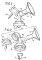
- FIG. 1 illustrates in broad overview an embodiment of a breastpump assembly 10 incorporating features of the present invention.
- the breastpump assembly includes a hood or shield 12, which extends into a tunnel or sleeve 14. Hood and shield are used interchangeably herein.
- a pressure-varying chamber in the form of a vacuum chamber 16 described in greater detail below is involved in the generation of changes in pressure for communication to the interior of the shield 12.
- a collar 18 may be provided for the releasable attachment of a milk bottle or like container (not shown) thereto.
- a conduit structure 19 connects and permits fluid communication between components of the breastpump assembly 10.
- the term "vacuum” connotes pressure reduction (e.g., below ambient pressure), sometimes also referred to herein as a negative pressure.
- a vacuum is the desired negative pressure change being developed within the shield 12 from vacuum chamber 16, it need not be the only pressure change capable of being generated.
- a positive pressure or overpressure could be applied to squeeze the breast, for instance (the breast, of course, constituting at least the nipple, but typically also some surrounding breast tissue). Details of a breastpump having these general components, but not having the inventive features that are described herein, can be further gleaned from U.S. Patent No. 6,110,140 , for example.
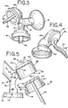
- the breastpump assembly 10 includes a pump mechanism (for example, see number 36 in FIG. 2 ) that is manually operable in a first mode of operation for the efficient expression of milk from a mother's breast (general pumping) and in a second mode of operation for stimulating an ejection reflex (letdown).
- the breastpump assembly 10 pump mechanism 36 may be a single mechanism having two different operating modes; a milk expression mode of operation or an ejection mode of operation.
- the pump mechanism 36 may be two separate mechanisms; each separate mechanism designed to provide either a milk expression or an ejection mode of operation.
- shield 12 and sleeve 14 attach to a shield mount 20, for example, in an interference fit.
- Shield 12 and sleeve 14 may be formed as a single unit or may be separate attachable units.
- the shield mount 20, conduit structure 19 and container collar 18 form base 21.
- the shape of the shield 12 and its formation with the base 21 of the breastpump assembly 10 are incidental; the particular arrangement and details of these elements is in no way limiting.
- One embodiment of the present invention includes a conduit structure 19, having a conduit surface 23 that defines one or more internal conduits 25.
- a conduit structure 19 is shown in FIG. 5 .
- the conduit structure 19 supports, connects and permits fluid communication between different termini such as between shield 12 at one terminus 11A, vacuum chamber 16 at a second terminus 11B, and a container (not shown) connected to collar 18 forming the third terminus 11C.
- valve mechanism 24, such as the one described in U.S. 4,929,229 is releasably attached to the conduit structure 19.
- the valve mechanism 24, shown in FIGS. 1 and 2 includes a flexible disk 26, which provides a flap valve for opening and closing the valve mechanism 24 provides communication between conduit structure 19 and an attached bottle.
- one embodiment of the vacuum chamber 16 is defined, in part, by rigid continuous sidewall 28 with top wall 30.
- Sidewall aperture 38, formed through rigid outer sidewall 28 allows communication between vacuum chamber 16 and conduit 25.
- the pump mechanism 36 includes an upper rigid disc or plate 40, flexible membrane 42, diaphragm collar 44 and lever 46, such that the pump mechanism 36 is lever driven.
- the upper plate 40 is spaced from top wall 30, and with sidewall 28 define chamber 16.
- Lever 46 is rigidly connected to plate 40.
- the pump mechanism 36 may include a collar 44 surrounding the circumference of the membrane 42, and a U-shaped channel 45 defined between spaced-apart sidewall portions 54, 56 sized and shaped to provide collar 44.
- the bottom edge 29 of the sidewall 28 is sized and shaped to fit snugly within the U-shaped channel 45 to mount the pump mechanism 36 within the vacuum chamber 16.
- lever 46 When inserted within the vacuum chamber 16, pump mechanism 36 is thereby generally sealed within vacuum chamber 16.
- plate 40 pivots away from top wall 30 about a pivot point 31.
- a hinge-like action occurs between the flexible diaphragm collar 44 and the sidewall 28 at this point 31.
- a simple finger movement can move lever 46, as by a mother grasping the breastpump assembly 10 (in place on the breast) with one hand, and pulling the lever 46 towards the conduit structure 19, i.e., toward her body (and against the base as a stop). This causes the membrane 42 to collapse opposite the point 31.
- the pump mechanism 36 As the collapse of the membrane 42 causes the pump mechanism 36 to increase the volume of the chamber 16 (defined by walls 28 and 30, plate 40 and membrane 42) such that a vacuum is thereby created in the chamber 16 on the stroke towards the mother's body.
- the vacuum extends through aperture 38 into the conduit 25, reducing the pressure within and thereby applying or creating a condition of vacuum in the shield 12 and drawing air into chamber 16.
- lever 46 When lever 46 is released, the natural resiliency of the membrane 42 causes the pump mechanism 36 to return to its rest position and occupy the chamber 16. Given that air may have been drawn into chamber 16, the return of the pump mechanism 36 to its rest position may cause a brief pressure condition above that of atmospheric pressure.
- the positive pressure thereby created can be used to open the flap valve 26 to assist in passing milk through the conduit 19 to the bottle or other container, with venting of the over-pressure through conventional means.
- a very easily operated one-handed manual pump mechanism 36 is thereby provided for operation in a first mode of operation for the efficient expression of breastmilk.
- One embodiment of the inventive breastpump also includes an ejection mechanism 32 for a second mode of operation of the breastpump assembly 10.
- ejection mechanism 32 has a flexible dome-shaped ejection "button" 33 attached to top wall 30.
- Top wall 30 has an aperture 34 formed therethrough such that an ejection chamber 35 under ejection button 33 is permitted fluid communication with vacuum chamber 16.
- ejection button 33 When ejection button 33 is depressed, as by a mother's finger, an initial positive pressure is created within the ejection chamber 35 and is communicated to vacuum chamber 16 by aperture 34. The initial positive pressure is in turn communicated to the conduit 25 from vacuum chamber 16 via sidewall aperture 38.
- ejection button 33 When ejection button 33 is released, it returns under its own resiliency to an initial dome shape, and provides a slight vacuum within ejection chamber 35, which is, in turn transmitted through aperture 34 to vacuum chamber 16 in like manner.
- a sequence is initiated, which can be referred to as an ejection sequence or a stimulation of the ejection reflex, which can be pronounced of the initial suckling of an infant causing the onset of milk ejection, e.g., relatively rapid but light pulling and pushing upon the nipple and breast.
- the mother uses pump mechanism 36 to create the main or primary intermittent vacuum sequence for milk expression.
- the ejection mechanism 32 need not be an integral part of the breastpump assembly 10.
- the mechanism 32 could communicate with the breastpump assembly 10 via tubing (not shown), which may be attachable to the breastpump assembly 10 for instance to the conduit structure 19, and be operated by the hand that is not holding the breastpump assembly 10 in place on the breast. It is also not limited to a flexible dome in a push-button arrangement, as described in this embodiment, although a simple finger-operated mechanism like this is considered most desirable.
- the expansible chamber devices could be used.
- the present invention may include a spring, elastomer or similar return device (not shown) by which the ejection button 33 may be urged back to a rest position from its pressed position.
- a spring could be disposed within chamber 35 between the top wall 30 and the button 33.
- assistant device could likewise be used with the primary pump mechanism 36 to place the lever 46 back to its initial or rest position.
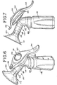
- FIG. 4 illustrates another embodiment of the present invention.
- the FIG. 4 embodiment includes lever 46' sized and shaped to accommodate the finger or fingers (not shown) of a user so as to provide an ergodynamic lever, having a smoothly curved outboard side 50.
- the lever 46' extends into a fastener 51, which connects with the plate 40.
- the outer surface 50 of the lever 46', as well as portions of the base (indicated at 60), is covered with a soft material for better grip and less stress on the hands.
- Thermoset elastomer or thermoplastic rubbers are just two generic types of material suitable for use as this soft outer layer.
- the breastpump assembly 110 includes a shield 112, for contacting the breast.
- the shield 112 is attached to a conduit structure 114.
- a vacuum pump mechanism 116 is attached to the conduit structure 114.
- the conduit structure 114 transmits vacuum generated in the vacuum pump mechanism 116 to the shield 112 and transmits expressed breastmilk from the shield to an attached container 118.
- the shield 112 has a generally funnel shaped portion 120 shaped and sized for being received onto a breast.
- the shield 112 extends into a sleeve 122 downstream from the funnel shaped portion 120.
- the sleeve 122 is open so as to conduct expressed milk into the conduit structure 114.
- the shape of the shield 112 and its formation with the conduit structure 114 are incidental; the particular arrangement and details of these elements is in no way limiting.
- the conduit structure 114 is attachable to the shield 112 through a shield mount 124 sized and shaped to receive the sleeve 122.
- the conduit structure 114 is generally a housing that interconnects and permits fluid communication between parts of the breastpump assembly 110.
- the conduit structure 114 connects to the sleeve 122, by way of the shield mount 124 at the one end, and terminates with a valve mechanism (see FIG. 2 , for example) as is known in the art at a container end 126.
- the container end 126 may include threads 128 or any suitable mechanism for releasable attachment to container 118, which may be in the form of a milk bottle or the like.
- the conduit structure 114 includes a first conduit 130 defined by an inner first conduit surface 132 for conducting expressed breast milk from the shield mount 124 through the valve mechanism and into the container 118.
- the conduit structure 114 includes a receptacle 134 for receiving the pump mechanism 116.
- the receptacle 134 may be a bore formed in the conduit structure 114 or a bore formed in a cylindrical extension (not shown) of the conduit structure 114.
- the receptacle 134 further includes a longitudinal bore 138 in fluid communication with a second conduit 140 for transmitting pressure changes generated in the pump mechanism 116 through the receptacle 134 and conduit structure 114.
- the second conduit 140 is in fluid communication with the first conduit 130 in chamber 141 so as to conduct pressure changes through the conduit structure 114 to the shield 112 and thence to a breast of a user.
- the pump mechanism 116 is releasably and even rotatably attachable to the conduit structure 114.
- the pump mechanism 116 includes two main portions.
- a first portion is a substantially rigid shell or handle 142.
- the second portion is a flexible movable member in the form of a diaphragm-like structure 144 attached to the handle.
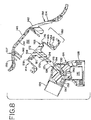
- the handle 142 may be made of a rigid plastic similar to that of the conduit structure 114. Referring to FIG. 8 in particular, handle 142 has a central portion 146, which has the form of a dome or housing, and a bottom edge portion 148.
- the dome 146 includes an inner surface 150, which defines a vacuum chamber 152 with the diaphragm 144 as will be explained more fully below.
- the handle 142 includes a first extension 154 in the form of a handle extending from a back side 156 of the handle 142, which is sized and shaped to be grasped by a hand or one or more digits of the user. Drawing the distal or first extension 154 toward the conduit structure 114 and generally toward the user's body operates the first extension 154 in the first mode of operation of the breastpump.
- a second or proximal extension 158 extends from the front side 157, opposite the first extension 154, in the form of a tab or smaller handle extension. The proximal or second extension 158 may be smaller than the first 154 and may be operated by drawing the extension downwardly toward the conduit structure 114 in the second mode of operation with a single digit of the user. Distal and proximal are used herein relative to the shield 112.
- the diaphragm 144 includes two main parts.
- a first part is a flexible portion 160, shaped like an inverted cup to be positioned inside the dome 146 of the handle 142 adjacent the inner surface 150 thereof.
- the flexible portion 160 includes an outer edge 162 with a channel 164 for tightly fitting with the dome shell edge 148.
- the flexible portion 160 is made of a naturally resilient material so that there is a tendency for the membrane to be resiliently returned to a starting position after being deflected in use.
- the membrane 160 includes a central concavity 180 on an upper surface thereof and a central opening 182 ( FIG. 9 ) to receive a puller 166. There is a thinned transition area 149 defining the middle of the flexible portion 160.
- the second part of the diaphragm 144 is a rigid member or puller 166.
- the puller 166 includes a disc portion 168 and an extension or post 170.
- the disc portion 168 is a generally flattened oval member that is centrally imbedded within or attached to the membrane 160 at the upper surface concavity 180 and may be held in place by posts 184 ( FIG. 9 ) of the membrane 160 inserted through holes 186, for example, such as four holes 186 arranged somewhat symmetrically around the disc portion.
- the disc portion 168 includes a central opening 172 that is open to the vacuum chamber 152 at an upper end thereof.
- the post 170 is a hollow cylindrical member that is attached to the disc portion 168.
- a hollow bore 174 of the post 170 is aligned to be in communication with the central opening 172 of the disc portion 168.
- the extension 170 is sized and shaped to be received within the post receptacle 134, preferably via a press or interference fit.
- the connection of the extension 170 to the post receptacle 134 is releasable and rotatable or pivotable in the receptacle 134.
- the entire handle 116 and extension 154 may be rotated to one side of the breastpump assembly for the convenience of the user.
- the puller 166 may be fixedly connected to the conduit structure 114.
- the assembly 110 may be formed as a unitary unit. For ease of cleaning, it is preferred to provide the various elements of the assembly 110 as separate elements. Accordingly, for the purpose of this invention, the term connected may refer to a releasable or a permanent connection.
- the lower end of the post 170 forms a half-lap feature 171, which when fitted to the receptacle 134 cooperates with a converse feature 173 within the bore of socket 134 to limit the arcuate travel of handle 116 and prevent over-rotation.
- FIG. 9A shows another way of mounting a modified disc portion 168 and membrane 160.
- the opening 182 in the membrane is further defined by a thickened ring or bead 183, which depends from a bottom surface opposite the concavity 180.
- Post 170 has a complementary channel 185 formed thereon, in which the bead 183 seats.
- the pump mechanism membrane 160 In operation, at a rest position, which is a start or initial position, the pump mechanism membrane 160 lies against or closely adjacent to the inner surface 150 of the dome portion 146 of the handle 142. In this position, as shown in FIG. 6 , the volume of the vacuum chamber 152 is zero or at a minimum volume.
- the first extension 154 When the user manipulates the first extension 154 by pulling the extension inwardly toward the conduit structure 114, the post 170 and disc portion 168 remain connected to and motionless with respect to the conduit structure while the handle 142 moves with the extension.
- the rigid disc portion 168 pivots about a point at a rear edge 176 thereof, causing the membrane 160 to pull away from the inner surface 150 of the dome 146, which expands the vacuum chamber 152 a first volume to produce a first negative pressure therein.
- the reduced pressure is communicated through the central opening 172 of the disc 168, through the hollow bore 174 of the post 170, through the longitudinal bore 138 of the receptacle 134, through the second conduit 140 and thence the shield 112.
- Operation of the breastpump 110 by this first mode of operation is intended to generate an amount of vacuum at a cyclical rate in order to efficiently promote milk expression from a breast, i.e., general pumping.
- a very easily operated one-handed manual pump mechanism is thereby provided that operates a manual breastpump in a first mode of operation to produce an efficient expression of breast milk.
- the handle 142 freely rotates in receptacle 134, enabling the user to adjust the handle's position to a - most convenient grasping orientation.
- the membrane 160 pulls away from the inner surface 150 of the dome 146 at a distal region by pivoting about a point at a front edge 178 of the disc, which expands the vacuum chamber 152 a second volume to produce a second negative pressure therein.
- the second volume may be less than the first volume so that a lesser relative change in pressure is generated by the second mode of operation as compared to the first mode.
- this difference may be due to the shape and travel of the first and second extensions 154, 158. That is, second extension travels a shorter distance before it is stopped by the hood mount 124. First extension 154 has a longer distance of travel before it is stopped by the conduit structure 114.
- the depth of the vacuum chamber adjacent the second extension 158 may be formed as to be greater than the depth of the chamber adjacent the first extension 154.
- Operation of the breastpump 110 by the second mode of operation is intended to generate an amount of vacuum (relatively less in absolute change) at a cyclical rate (which may be relatively more rapid) in order to efficiently promote a milk ejection reflex. It can be seen that use of a small extension 158 is possible and efficient to promote ejection due to the lesser amount of vacuum generated in the second mode of operation. Because of the lesser amount of force necessary the second mode of operation may occur relatively more rapidly, which, it has been found, is desired to produce ejection as compared to expression.
- the pump mechanism is capable of generating both ejection and expression operation.
- limiting the travel of either the extension 154, 158 and displacement of the diaphragm thereby creates a relatively lesser change in pressure when compared to the first mode of operation.
- the extension 154 may be permitted to travel a distance in the first mode of operation to produce a vacuum designed to efficiently express milk, e.g., from about 100-250 mmHg.
- the extension 154 or 158 may be permitted to travel a distance in the second mode of operation to produce a negative pressure change designed to stimulate an ejection reflex, e.g., from about 50-150 mmHg.
- the frequency of intermittent operation of the extension 158 during the ejection mode of operation may be twice the frequency or greater than that used during the expression mode of operation. Further, because the travel is limited in the second mode of operation, the frequency of movement of the extension 158 can be easily increased as compared to the operation of the pump mechanism 116 in the first mode of operation.
- the second mode of operation including operating the breastpump 110 at a relatively higher frequency and a relatively lower change in pressure produces letdown in the nursing mother much more successfully than operation of the breastpump in a set of conditions designed for general expression of milk.
- indicia could be provided to assist the user in determining the amount of travel or displacement of the pump mechanism 116 in order to vary the pumping conditions and parameters to provide the first and second modes of operation with a single extension. Further, stops could be adopted for regulating the travel of the extension 154 correspondingly to "Max", “Med” and “Min” levels of vacuum.
- FIG. 11 shows another embodiment of a puller 266 for use in the breastpump of the present invention.
- the depicted puller generally has the same function of the puller shown in FIGS. 8-10 .
- the puller 266 includes a disc portion 268 connected or integrally molded with a extension 270.
- the disc portion 268 may be oval as depicted or any suitable shape.
- the extension 270 may be essentially cylindrical post with a hollow axial bore 274.
- the distal end of the extension 270 includes a stop feature 271 which permits rotation of the puller a predetermined amount. In this manner, the handle (see FIG. 6 ) pivots and the breastpump are usable in a great array of configurations.
- This embodiment of the puller 266 includes o-rings 288 fitted about a mid-span of the extension 270. It will be understood that the o-rings 288 provide a fluid-tight seal with a corresponding socket (see FIG. 8 ) of the breastpump and permits rotation of the handle with respect to the conduit to which it is attached. Furthermore, the extension 270 includes a shoulder 290, which limits the insertion of the extension.
Claims (6)
- Eine manuelle Brustpumpe (10), wobei die Brustpumpe aufweist:
einen Milchabpumpmechanismus (36) mit einem Hebel (46), der verbunden ist mit einer flexiblen Membran (42) zur Ausbildung einer expandierbaren Vakuumkammer (16), um eine primären Druck zu erzeugen zum Anlegen einer intermittierenden Kraft auf einen Bereich einer in einer Haube (12) angeordneten Mutterbrust, dadurch gekennzeichnet, dass die Brustpumpe ferner einen manuell betätigten Milchejektionsmechanismus (32) aufweist mit einem flexiblen domförmigen Ejektionsknopf (33), der an einer oberen Wand (30) der Vakuumkammer (16) befestigt ist, so dass eine Ejektionskammer (35), die unterhalb des Ejektionsknopfes (33) ausgebildet ist, in Fluidkommunikation mit der Vakuumkammer (16) stehen kann, um einen sekundären Druck zu generieren, der kleiner ist als der primäre Druck, und welcher der Haube (12) kommuniziert wird, um Milchfluss (let-down) zu bewirken. - Die Brustpumpe nach Anspruch 1, wobei der Milchejektionsmechanismus (32) im Allgemeinen in einer relativ zur einer mittels der Betätigung des Abpumpmechanismus erzeugten Frequenz des primären Drucks schnellen Art und Weise betätigbar ist.
- Die Brustpumpe nach Anspruch 1, wobei die Haube (12) mit einer Haubenbasis (21) verbunden ist, die eine Leitungsstruktur (19) aufweist, wobei die Leitungsstruktur (19) die Drücke zur Haube (12) leitet und durch welche die von der Brust abgepumpte Milch von der Haube (12) zu einem Behälter transportiert wird.
- Die Brustpumpe nach Anspruch 3, wobei der manuell betätigte Milchejektionsmechanismus (32) bemessen und angeordnet ist, um mit einem Finger der Mutter betätigt zu werden, wobei die Haubenbasis (21) geeignet ist, um mit einer Hand gehalten zu werden.
- Die Brustpumpe nach Anspruch 1, wobei der manuell betätigte Milchejektionsmechanismus (32) ferner aufweist:
eine Öffnung (34), ausgebildet in der oberen Wand (30) der Vakuumkammer (16), wobei der flexible Dom (33) von Hand in Richtung Dombasis pressbar ist, um dabei den sekundären Druck zu erzeugen. - Die Brustpumpe nach Anspruch 1, wobei der primäre Druck und der sekundäre Druck je eine Druckänderung aufweisen, die intermittierend angewendet ist.
Applications Claiming Priority (4)
| Application Number | Priority Date | Filing Date | Title |
|---|---|---|---|
| US40555902P | 2002-08-23 | 2002-08-23 | |
| US10/424,887 US7727182B2 (en) | 2002-08-23 | 2003-04-28 | Manual breastpump with stimulation feature |
| EP03793295.1A EP1536851B1 (de) | 2002-08-23 | 2003-08-22 | Manuelle brustpumpe mit stimulationsmöglichkeit |
| PCT/US2003/026355 WO2004018018A2 (en) | 2002-08-23 | 2003-08-22 | Manual breastpump with stimulation feature |
Related Parent Applications (2)
| Application Number | Title | Priority Date | Filing Date |
|---|---|---|---|
| EP03793295.1A Division EP1536851B1 (de) | 2002-08-23 | 2003-08-22 | Manuelle brustpumpe mit stimulationsmöglichkeit |
| EP03793295.1A Division-Into EP1536851B1 (de) | 2002-08-23 | 2003-08-22 | Manuelle brustpumpe mit stimulationsmöglichkeit |
Publications (2)
| Publication Number | Publication Date |
|---|---|
| EP2722063A1 EP2722063A1 (de) | 2014-04-23 |
| EP2722063B1 true EP2722063B1 (de) | 2019-10-02 |
Family
ID=31891509
Family Applications (2)
| Application Number | Title | Priority Date | Filing Date |
|---|---|---|---|
| EP13192416.9A Expired - Lifetime EP2722063B1 (de) | 2002-08-23 | 2003-08-22 | Manuelle Brustpumpe mit Stimulationsmöglichkeit |
| EP03793295.1A Expired - Lifetime EP1536851B1 (de) | 2002-08-23 | 2003-08-22 | Manuelle brustpumpe mit stimulationsmöglichkeit |
Family Applications After (1)
| Application Number | Title | Priority Date | Filing Date |
|---|---|---|---|
| EP03793295.1A Expired - Lifetime EP1536851B1 (de) | 2002-08-23 | 2003-08-22 | Manuelle brustpumpe mit stimulationsmöglichkeit |
Country Status (11)
| Country | Link |
|---|---|
| US (3) | US7727182B2 (de) |
| EP (2) | EP2722063B1 (de) |
| JP (1) | JP5007023B2 (de) |
| KR (1) | KR100977749B1 (de) |
| AU (1) | AU2003262799C1 (de) |
| CA (1) | CA2495380C (de) |
| ES (2) | ES2758752T3 (de) |
| IL (1) | IL166902A (de) |
| MX (1) | MXPA05002063A (de) |
| NZ (1) | NZ538400A (de) |
| WO (1) | WO2004018018A2 (de) |
Families Citing this family (29)
| Publication number | Priority date | Publication date | Assignee | Title |
|---|---|---|---|---|
| US6749582B2 (en) | 2002-04-30 | 2004-06-15 | The First Years Inc. | Pumping breast milk |
| US7727182B2 (en) * | 2002-08-23 | 2010-06-01 | Medela Holding Ag | Manual breastpump with stimulation feature |
| US7776008B2 (en) * | 2003-08-08 | 2010-08-17 | Playtex Products, Inc. | Manual breast pump |
| US20050154348A1 (en) * | 2004-01-08 | 2005-07-14 | Daniel Lantz | Breast pump |
| JP4413231B2 (ja) * | 2005-08-09 | 2010-02-10 | ピジョン株式会社 | 搾乳器 |
| US20070060873A1 (en) * | 2005-09-15 | 2007-03-15 | Katsuyuki Hiraoka | Milking apparatus |
| WO2007120622A2 (en) * | 2006-04-11 | 2007-10-25 | Playtex Products, Inc | Manual breast pump |
| US9162016B2 (en) * | 2006-09-22 | 2015-10-20 | Medela Holding Ag | Breastpump with irregular milk expression sequences |
| US8187227B2 (en) * | 2006-11-01 | 2012-05-29 | Medela Holding Ag | Self returning contamination barrier |
| US8070716B2 (en) * | 2007-04-11 | 2011-12-06 | Medela Holding Ag | Method and apparatus for minimum negative pressure control, particularly for a breastpump with breastshield pressure control system |
| US8070715B2 (en) | 2007-04-11 | 2011-12-06 | Medela Holding Ag | Method and apparatus for minimum negative pressure control, particularly for breastpump with breastshield pressure control system |
| AU2008246934A1 (en) * | 2007-05-07 | 2008-11-13 | Carmeli Adahan | Suction system |
| US8323235B2 (en) * | 2008-11-07 | 2012-12-04 | Handi-Craft Company | Liner for use with a breast pump |
| WO2010083485A2 (en) | 2009-01-16 | 2010-07-22 | Learning Curve Brands, Inc. | Breast pump and method of use |
| EP2324868A1 (de) * | 2009-07-28 | 2011-05-25 | Koninklijke Philips Electronics N.V. | Flexibler Antrieb für Brustpumpe |
| US8357116B2 (en) | 2010-08-10 | 2013-01-22 | Medela Holding Ag | Bag attachment device for breastpump |
| DE202012008803U1 (de) * | 2012-09-14 | 2013-12-16 | Mapa Gmbh | Manuelle Muttermilchpumpe |
| EP3256182B1 (de) * | 2015-02-10 | 2020-03-25 | Medela Holding AG | Medientrennvorrichtung |
| USD785160S1 (en) * | 2015-02-20 | 2017-04-25 | Medela Holding Ag | Membrane for a breastshield of a breast pump |
| MX2018002379A (es) * | 2015-08-27 | 2018-04-11 | Medela Holding Ag | Sistema de seguridad de extractor de leche y metodo para sistema de bomba. |
| US20180043070A1 (en) * | 2016-08-11 | 2018-02-15 | Target Brands, Inc. | Breast milk collection system with bag attachment |
| TWM589054U (zh) * | 2017-11-30 | 2020-01-11 | 紐西蘭商想綠有限公司 | 吸乳器及餵食套組 |
| KR20200096801A (ko) * | 2017-12-05 | 2020-08-13 | 메델라 홀딩 아게 | 리테이닝 렛지를 갖는 풀러를 포함하는 다이어프램 조립체 |
| EP3517148A1 (de) * | 2018-01-24 | 2019-07-31 | Koninklijke Philips N.V. | Bestimmung des brustzustandes |
| USD898184S1 (en) | 2019-01-29 | 2020-10-06 | Handi-Craft Company | Breast pump valve |
| CN114901339A (zh) * | 2019-11-20 | 2022-08-12 | Clph有限责任公司 | 隔离和附接导管及其使用方法 |
| USD963835S1 (en) * | 2020-10-30 | 2022-09-13 | Hygeia Ii Medical Group, Inc. | Breast pump |
| CN218774137U (zh) * | 2020-12-16 | 2023-03-31 | 皇家飞利浦有限公司 | 吸乳泵系统和用于吸乳泵系统的套件 |
| EP4359027A1 (de) * | 2021-06-22 | 2024-05-01 | Bard Peripheral Vascular, Inc. | Drainagesystem mit flüssigkeitssammelvorrichtung mit wählbarem unterdruck zum entleeren und sammeln von körperflüssigkeiten aus einer körperhöhle |
Family Cites Families (20)
| Publication number | Priority date | Publication date | Assignee | Title |
|---|---|---|---|---|
| US37677A (en) | 1863-02-17 | Improvements breast-pumps | ||
| US50457A (en) * | 1865-10-17 | Improvement in breast-pumps | ||
| US4263912A (en) * | 1977-06-08 | 1981-04-28 | Adams Frank H | Milking apparatus and method |
| US4323067A (en) * | 1977-06-20 | 1982-04-06 | Adams Frank H | Combination breast pump and gavage feeding apparatus and method |
| US4857051A (en) | 1980-09-05 | 1989-08-15 | Isg/Ag | Breastpump |
| DE3419613A1 (de) | 1984-05-25 | 1985-11-28 | Kirchner & Wilhelm, 7000 Stuttgart | Muttermilchabsaugvorrichtung |
| GB8422861D0 (en) | 1984-09-11 | 1984-10-17 | Avent Medical Ltd | Single handed breast pump |
| US4929229A (en) | 1988-11-30 | 1990-05-29 | Isg/Ag | Breastpump having improved valve mechanism |
| US5415632A (en) * | 1994-01-10 | 1995-05-16 | Playskool, Inc. | Breast pump |
| GB2299027B (en) * | 1995-03-24 | 1999-02-17 | Cannon Rubber Ltd | Diaphragm breast pump |
| US6547756B1 (en) | 1999-12-10 | 2003-04-15 | Medela Holding Ag | Programmable breastpump |
| US5843029A (en) | 1995-10-16 | 1998-12-01 | Gerber/Baby Care | Manual breast pump |
| US6887210B2 (en) * | 2000-11-13 | 2005-05-03 | Atossa Healthcare, Inc. | Devices and methods for obtaining mammary fluid samples for evaluating breast diseases, including cancer |
| US6110140A (en) | 1996-09-17 | 2000-08-29 | Medela, Inc. | Manual breastmilk pump |
| DE19954112A1 (de) * | 1999-11-11 | 2001-06-13 | Kaweco Gmbh | Milchabsaugpumpe |
| ES2589732T3 (es) | 1999-12-10 | 2016-11-16 | Medela Holding Ag | Sacaleches |
| GB0119074D0 (en) * | 2001-08-06 | 2001-09-26 | Handley Kuester Ltd | Breast pumps |
| US6749582B2 (en) * | 2002-04-30 | 2004-06-15 | The First Years Inc. | Pumping breast milk |
| GB0214525D0 (en) * | 2002-06-24 | 2002-08-07 | Samson Ilan | Breast pump |
| US7727182B2 (en) * | 2002-08-23 | 2010-06-01 | Medela Holding Ag | Manual breastpump with stimulation feature |
-
2003
- 2003-04-28 US US10/424,887 patent/US7727182B2/en active Active
- 2003-08-22 AU AU2003262799A patent/AU2003262799C1/en not_active Ceased
- 2003-08-22 JP JP2004529857A patent/JP5007023B2/ja not_active Expired - Fee Related
- 2003-08-22 EP EP13192416.9A patent/EP2722063B1/de not_active Expired - Lifetime
- 2003-08-22 NZ NZ538400A patent/NZ538400A/en unknown
- 2003-08-22 ES ES13192416T patent/ES2758752T3/es not_active Expired - Lifetime
- 2003-08-22 MX MXPA05002063A patent/MXPA05002063A/es active IP Right Grant
- 2003-08-22 WO PCT/US2003/026355 patent/WO2004018018A2/en active Application Filing
- 2003-08-22 EP EP03793295.1A patent/EP1536851B1/de not_active Expired - Lifetime
- 2003-08-22 KR KR1020057003048A patent/KR100977749B1/ko active IP Right Grant
- 2003-08-22 CA CA2495380A patent/CA2495380C/en not_active Expired - Fee Related
- 2003-08-22 ES ES03793295.1T patent/ES2564822T3/es not_active Expired - Lifetime
-
2005
- 2005-02-15 IL IL166902A patent/IL166902A/en active IP Right Grant
-
2010
- 2010-02-24 US US12/711,783 patent/US8430842B2/en not_active Expired - Lifetime
-
2013
- 2013-04-15 US US13/862,933 patent/US10052417B2/en not_active Expired - Lifetime
Non-Patent Citations (1)
| Title |
|---|
| None * |
Also Published As
| Publication number | Publication date |
|---|---|
| US20100217183A1 (en) | 2010-08-26 |
| EP1536851A2 (de) | 2005-06-08 |
| KR20050046738A (ko) | 2005-05-18 |
| EP2722063A1 (de) | 2014-04-23 |
| EP1536851B1 (de) | 2015-12-23 |
| JP5007023B2 (ja) | 2012-08-22 |
| AU2003262799A1 (en) | 2004-03-11 |
| KR100977749B1 (ko) | 2010-08-24 |
| US20040039330A1 (en) | 2004-02-26 |
| WO2004018018A2 (en) | 2004-03-04 |
| CA2495380A1 (en) | 2004-03-04 |
| NZ538400A (en) | 2006-10-27 |
| IL166902A (en) | 2013-09-30 |
| US7727182B2 (en) | 2010-06-01 |
| WO2004018018A3 (en) | 2004-07-01 |
| MXPA05002063A (es) | 2005-06-08 |
| EP1536851A4 (de) | 2008-12-03 |
| ES2758752T3 (es) | 2020-05-06 |
| US10052417B2 (en) | 2018-08-21 |
| AU2003262799C1 (en) | 2008-02-21 |
| CA2495380C (en) | 2011-11-01 |
| US20130226147A1 (en) | 2013-08-29 |
| ES2564822T3 (es) | 2016-03-29 |
| US8430842B2 (en) | 2013-04-30 |
| AU2003262799B2 (en) | 2007-08-09 |
| JP2005536261A (ja) | 2005-12-02 |
Similar Documents
| Publication | Publication Date | Title |
|---|---|---|
| US8430842B2 (en) | Manual breastpump with stimulation feature | |
| US9199017B2 (en) | Breastpump with letdown feature | |
| US20100292636A1 (en) | Manual breast pump | |
| US20090062731A1 (en) | Breast Pump | |
| JP2005536261A5 (de) | ||
| CA2240268A1 (en) | Breast pump assembly | |
| US20220184283A1 (en) | Cushion configured to be mounted to an air passage element of a breast pump device | |
| CN211610990U (zh) | 一种电动手动切换式吸奶器 | |
| EP0198651A2 (de) | Vorrichtung zur Erzeugung eines Vakuums an einer Stelle eines menschlichen oder tierischen Körpers |
Legal Events
| Date | Code | Title | Description |
|---|---|---|---|
| PUAI | Public reference made under article 153(3) epc to a published international application that has entered the european phase |
Free format text: ORIGINAL CODE: 0009012 |
|
| AC | Divisional application: reference to earlier application |
Ref document number: 1536851 Country of ref document: EP Kind code of ref document: P |
|
| AK | Designated contracting states |
Kind code of ref document: A1 Designated state(s): AT BE BG CH CY CZ DE DK EE ES FI FR GB GR HU IE IT LI LU MC NL PT RO SE SI SK TR |
|
| 17P | Request for examination filed |
Effective date: 20140901 |
|
| RBV | Designated contracting states (corrected) |
Designated state(s): AT BE BG CH CY CZ DE DK EE ES FI FR GB GR HU IE IT LI LU MC NL PT RO SE SI SK TR |
|
| REG | Reference to a national code |
Ref country code: HK Ref legal event code: DE Ref document number: 1195274 Country of ref document: HK |
|
| STAA | Information on the status of an ep patent application or granted ep patent |
Free format text: STATUS: EXAMINATION IS IN PROGRESS |
|
| 17Q | First examination report despatched |
Effective date: 20170405 |
|
| RIC1 | Information provided on ipc code assigned before grant |
Ipc: A61M 1/06 20060101AFI20190307BHEP Ipc: A61M 1/00 20060101ALI20190307BHEP |
|
| GRAP | Despatch of communication of intention to grant a patent |
Free format text: ORIGINAL CODE: EPIDOSNIGR1 |
|
| STAA | Information on the status of an ep patent application or granted ep patent |
Free format text: STATUS: GRANT OF PATENT IS INTENDED |
|
| INTG | Intention to grant announced |
Effective date: 20190418 |
|
| GRAS | Grant fee paid |
Free format text: ORIGINAL CODE: EPIDOSNIGR3 |
|
| GRAA | (expected) grant |
Free format text: ORIGINAL CODE: 0009210 |
|
| STAA | Information on the status of an ep patent application or granted ep patent |
Free format text: STATUS: THE PATENT HAS BEEN GRANTED |
|
| AC | Divisional application: reference to earlier application |
Ref document number: 1536851 Country of ref document: EP Kind code of ref document: P |
|
| AK | Designated contracting states |
Kind code of ref document: B1 Designated state(s): AT BE BG CH CY CZ DE DK EE ES FI FR GB GR HU IE IT LI LU MC NL PT RO SE SI SK TR |
|
| REG | Reference to a national code |
Ref country code: GB Ref legal event code: FG4D |
|
| REG | Reference to a national code |
Ref country code: CH Ref legal event code: EP Ref country code: AT Ref legal event code: REF Ref document number: 1185485 Country of ref document: AT Kind code of ref document: T Effective date: 20191015 |
|
| REG | Reference to a national code |
Ref country code: DE Ref legal event code: R096 Ref document number: 60352256 Country of ref document: DE |
|
| REG | Reference to a national code |
Ref country code: IE Ref legal event code: FG4D |
|
| REG | Reference to a national code |
Ref country code: CH Ref legal event code: NV Representative=s name: ISLER AND PEDRAZZINI AG, CH |
|
| REG | Reference to a national code |
Ref country code: NL Ref legal event code: MP Effective date: 20191002 |
|
| REG | Reference to a national code |
Ref country code: AT Ref legal event code: MK05 Ref document number: 1185485 Country of ref document: AT Kind code of ref document: T Effective date: 20191002 |
|
| PG25 | Lapsed in a contracting state [announced via postgrant information from national office to epo] |
Ref country code: PT Free format text: LAPSE BECAUSE OF FAILURE TO SUBMIT A TRANSLATION OF THE DESCRIPTION OR TO PAY THE FEE WITHIN THE PRESCRIBED TIME-LIMIT Effective date: 20200203 Ref country code: BG Free format text: LAPSE BECAUSE OF FAILURE TO SUBMIT A TRANSLATION OF THE DESCRIPTION OR TO PAY THE FEE WITHIN THE PRESCRIBED TIME-LIMIT Effective date: 20200102 Ref country code: FI Free format text: LAPSE BECAUSE OF FAILURE TO SUBMIT A TRANSLATION OF THE DESCRIPTION OR TO PAY THE FEE WITHIN THE PRESCRIBED TIME-LIMIT Effective date: 20191002 Ref country code: GR Free format text: LAPSE BECAUSE OF FAILURE TO SUBMIT A TRANSLATION OF THE DESCRIPTION OR TO PAY THE FEE WITHIN THE PRESCRIBED TIME-LIMIT Effective date: 20200103 Ref country code: SE Free format text: LAPSE BECAUSE OF FAILURE TO SUBMIT A TRANSLATION OF THE DESCRIPTION OR TO PAY THE FEE WITHIN THE PRESCRIBED TIME-LIMIT Effective date: 20191002 Ref country code: NL Free format text: LAPSE BECAUSE OF FAILURE TO SUBMIT A TRANSLATION OF THE DESCRIPTION OR TO PAY THE FEE WITHIN THE PRESCRIBED TIME-LIMIT Effective date: 20191002 Ref country code: AT Free format text: LAPSE BECAUSE OF FAILURE TO SUBMIT A TRANSLATION OF THE DESCRIPTION OR TO PAY THE FEE WITHIN THE PRESCRIBED TIME-LIMIT Effective date: 20191002 |
|
| REG | Reference to a national code |
Ref country code: ES Ref legal event code: FG2A Ref document number: 2758752 Country of ref document: ES Kind code of ref document: T3 Effective date: 20200506 |
|
| PG25 | Lapsed in a contracting state [announced via postgrant information from national office to epo] |
Ref country code: CZ Free format text: LAPSE BECAUSE OF FAILURE TO SUBMIT A TRANSLATION OF THE DESCRIPTION OR TO PAY THE FEE WITHIN THE PRESCRIBED TIME-LIMIT Effective date: 20191002 |
|
| REG | Reference to a national code |
Ref country code: DE Ref legal event code: R097 Ref document number: 60352256 Country of ref document: DE |
|
| PG25 | Lapsed in a contracting state [announced via postgrant information from national office to epo] |
Ref country code: DK Free format text: LAPSE BECAUSE OF FAILURE TO SUBMIT A TRANSLATION OF THE DESCRIPTION OR TO PAY THE FEE WITHIN THE PRESCRIBED TIME-LIMIT Effective date: 20191002 Ref country code: EE Free format text: LAPSE BECAUSE OF FAILURE TO SUBMIT A TRANSLATION OF THE DESCRIPTION OR TO PAY THE FEE WITHIN THE PRESCRIBED TIME-LIMIT Effective date: 20191002 Ref country code: RO Free format text: LAPSE BECAUSE OF FAILURE TO SUBMIT A TRANSLATION OF THE DESCRIPTION OR TO PAY THE FEE WITHIN THE PRESCRIBED TIME-LIMIT Effective date: 20191002 |
|
| PLBE | No opposition filed within time limit |
Free format text: ORIGINAL CODE: 0009261 |
|
| STAA | Information on the status of an ep patent application or granted ep patent |
Free format text: STATUS: NO OPPOSITION FILED WITHIN TIME LIMIT |
|
| PG25 | Lapsed in a contracting state [announced via postgrant information from national office to epo] |
Ref country code: SK Free format text: LAPSE BECAUSE OF FAILURE TO SUBMIT A TRANSLATION OF THE DESCRIPTION OR TO PAY THE FEE WITHIN THE PRESCRIBED TIME-LIMIT Effective date: 20191002 Ref country code: IT Free format text: LAPSE BECAUSE OF FAILURE TO SUBMIT A TRANSLATION OF THE DESCRIPTION OR TO PAY THE FEE WITHIN THE PRESCRIBED TIME-LIMIT Effective date: 20191002 |
|
| 26N | No opposition filed |
Effective date: 20200703 |
|
| PGFP | Annual fee paid to national office [announced via postgrant information from national office to epo] |
Ref country code: ES Payment date: 20200901 Year of fee payment: 18 Ref country code: TR Payment date: 20200807 Year of fee payment: 18 |
|
| PG25 | Lapsed in a contracting state [announced via postgrant information from national office to epo] |
Ref country code: SI Free format text: LAPSE BECAUSE OF FAILURE TO SUBMIT A TRANSLATION OF THE DESCRIPTION OR TO PAY THE FEE WITHIN THE PRESCRIBED TIME-LIMIT Effective date: 20191002 |
|
| PGFP | Annual fee paid to national office [announced via postgrant information from national office to epo] |
Ref country code: CH Payment date: 20200903 Year of fee payment: 18 |
|
| PG25 | Lapsed in a contracting state [announced via postgrant information from national office to epo] |
Ref country code: MC Free format text: LAPSE BECAUSE OF FAILURE TO SUBMIT A TRANSLATION OF THE DESCRIPTION OR TO PAY THE FEE WITHIN THE PRESCRIBED TIME-LIMIT Effective date: 20191002 |
|
| PG25 | Lapsed in a contracting state [announced via postgrant information from national office to epo] |
Ref country code: LU Free format text: LAPSE BECAUSE OF NON-PAYMENT OF DUE FEES Effective date: 20200822 |
|
| REG | Reference to a national code |
Ref country code: BE Ref legal event code: MM Effective date: 20200831 |
|
| PG25 | Lapsed in a contracting state [announced via postgrant information from national office to epo] |
Ref country code: FR Free format text: LAPSE BECAUSE OF NON-PAYMENT OF DUE FEES Effective date: 20200831 |
|
| PG25 | Lapsed in a contracting state [announced via postgrant information from national office to epo] |
Ref country code: BE Free format text: LAPSE BECAUSE OF NON-PAYMENT OF DUE FEES Effective date: 20200831 Ref country code: IE Free format text: LAPSE BECAUSE OF NON-PAYMENT OF DUE FEES Effective date: 20200822 |
|
| PGFP | Annual fee paid to national office [announced via postgrant information from national office to epo] |
Ref country code: DE Payment date: 20210827 Year of fee payment: 19 Ref country code: GB Payment date: 20210827 Year of fee payment: 19 |
|
| REG | Reference to a national code |
Ref country code: CH Ref legal event code: PL |
|
| PG25 | Lapsed in a contracting state [announced via postgrant information from national office to epo] |
Ref country code: LI Free format text: LAPSE BECAUSE OF NON-PAYMENT OF DUE FEES Effective date: 20210831 Ref country code: CH Free format text: LAPSE BECAUSE OF NON-PAYMENT OF DUE FEES Effective date: 20210831 |
|
| PG25 | Lapsed in a contracting state [announced via postgrant information from national office to epo] |
Ref country code: CY Free format text: LAPSE BECAUSE OF FAILURE TO SUBMIT A TRANSLATION OF THE DESCRIPTION OR TO PAY THE FEE WITHIN THE PRESCRIBED TIME-LIMIT Effective date: 20191002 |
|
| REG | Reference to a national code |
Ref country code: ES Ref legal event code: FD2A Effective date: 20220930 |
|
| PG25 | Lapsed in a contracting state [announced via postgrant information from national office to epo] |
Ref country code: ES Free format text: LAPSE BECAUSE OF NON-PAYMENT OF DUE FEES Effective date: 20210823 |
|
| REG | Reference to a national code |
Ref country code: DE Ref legal event code: R119 Ref document number: 60352256 Country of ref document: DE |
|
| GBPC | Gb: european patent ceased through non-payment of renewal fee |
Effective date: 20220822 |
|
| P01 | Opt-out of the competence of the unified patent court (upc) registered |
Effective date: 20230524 |
|
| PG25 | Lapsed in a contracting state [announced via postgrant information from national office to epo] |
Ref country code: DE Free format text: LAPSE BECAUSE OF NON-PAYMENT OF DUE FEES Effective date: 20230301 |
|
| PG25 | Lapsed in a contracting state [announced via postgrant information from national office to epo] |
Ref country code: GB Free format text: LAPSE BECAUSE OF NON-PAYMENT OF DUE FEES Effective date: 20220822 |