EP2721918A2 - Wickler zur Umwicklung von Ballen aus Erntegut - Google Patents
Wickler zur Umwicklung von Ballen aus Erntegut Download PDFInfo
- Publication number
- EP2721918A2 EP2721918A2 EP13197803.3A EP13197803A EP2721918A2 EP 2721918 A2 EP2721918 A2 EP 2721918A2 EP 13197803 A EP13197803 A EP 13197803A EP 2721918 A2 EP2721918 A2 EP 2721918A2
- Authority
- EP
- European Patent Office
- Prior art keywords
- loading
- bale
- wrapper
- arms
- wrapping
- Prior art date
- Legal status (The legal status is an assumption and is not a legal conclusion. Google has not performed a legal analysis and makes no representation as to the accuracy of the status listed.)
- Granted
Links
Images




Classifications
-
- A—HUMAN NECESSITIES
- A01—AGRICULTURE; FORESTRY; ANIMAL HUSBANDRY; HUNTING; TRAPPING; FISHING
- A01D—HARVESTING; MOWING
- A01D87/00—Loaders for hay or like field crops
- A01D87/12—Loaders for sheaves, stacks or bales
-
- A—HUMAN NECESSITIES
- A01—AGRICULTURE; FORESTRY; ANIMAL HUSBANDRY; HUNTING; TRAPPING; FISHING
- A01F—PROCESSING OF HARVESTED PRODUCE; HAY OR STRAW PRESSES; DEVICES FOR STORING AGRICULTURAL OR HORTICULTURAL PRODUCE
- A01F15/00—Baling presses for straw, hay or the like
- A01F15/07—Rotobalers, i.e. machines for forming cylindrical bales by winding and pressing
- A01F15/071—Wrapping devices
-
- A—HUMAN NECESSITIES
- A01—AGRICULTURE; FORESTRY; ANIMAL HUSBANDRY; HUNTING; TRAPPING; FISHING
- A01D—HARVESTING; MOWING
- A01D87/00—Loaders for hay or like field crops
- A01D87/12—Loaders for sheaves, stacks or bales
- A01D87/122—Loaders for sheaves, stacks or bales for bales on the ground
-
- A—HUMAN NECESSITIES
- A01—AGRICULTURE; FORESTRY; ANIMAL HUSBANDRY; HUNTING; TRAPPING; FISHING
- A01F—PROCESSING OF HARVESTED PRODUCE; HAY OR STRAW PRESSES; DEVICES FOR STORING AGRICULTURAL OR HORTICULTURAL PRODUCE
- A01F15/00—Baling presses for straw, hay or the like
- A01F15/07—Rotobalers, i.e. machines for forming cylindrical bales by winding and pressing
-
- A—HUMAN NECESSITIES
- A01—AGRICULTURE; FORESTRY; ANIMAL HUSBANDRY; HUNTING; TRAPPING; FISHING
- A01F—PROCESSING OF HARVESTED PRODUCE; HAY OR STRAW PRESSES; DEVICES FOR STORING AGRICULTURAL OR HORTICULTURAL PRODUCE
- A01F15/00—Baling presses for straw, hay or the like
- A01F15/08—Details
- A01F15/14—Tying devices specially adapted for baling presses
-
- A—HUMAN NECESSITIES
- A01—AGRICULTURE; FORESTRY; ANIMAL HUSBANDRY; HUNTING; TRAPPING; FISHING
- A01F—PROCESSING OF HARVESTED PRODUCE; HAY OR STRAW PRESSES; DEVICES FOR STORING AGRICULTURAL OR HORTICULTURAL PRODUCE
- A01F15/00—Baling presses for straw, hay or the like
- A01F15/07—Rotobalers, i.e. machines for forming cylindrical bales by winding and pressing
- A01F15/071—Wrapping devices
- A01F2015/0755—Configuration of support surfaces which can move in order to rotate a bale around at least one axis while wrapping
Definitions
- the present invention relates to a wrapper for wrapping bales, in particular bales of crop material according to the preamble of claim 1.
- wrappers of this type are known in the art.
- the wrapper comprises a wrapping table mounted on a frame to support the bale during wrapping, and a wrapping device mounted on the frame to wrap wrapping material about the bale.
- a loading device may be provided to load a bale to be wrapped from a ground surface on the wrapping table.
- the loading device is typically a pivotable support structure which can be moved from a pick-up position in which a bale can be picked up from the ground surface to a release position in which the bale can be placed on the wrapping table.
- the pivotable support structure usually comprises two loading arms between which the bale can be arranged.
- a first type of loading devices friction fit is used to lift the bale from the pick-up position to the release position.
- the loading arms are arranged at opposite sides of the bales, and moved towards each other. By the resulting compression force, the bale is held between the two loading arms so that the bale can be lifted from the ground surface.
- An example of this type of wrapper is the "ELHO Sideliner" manufactured by Elho, Pännäinen Finland, also described in Finnish patent publication F1117504 .
- a drawback of this type of loading device is that the use of forces exerted on the bale to hold the bale by friction may be less reliable, in particular when bales of low compressed crop material are lifted.
- pivotable grip arms are provided at the distal end of the loading arms, which grip arms can be placed in an open position and a closed position. In the open position, the distance between the grip arms is larger than the width of a bale to be wrapped. In this open position of the grip arms, a bale can be positioned between the two loading arms when the wrapper is driven towards this bale.
- the grip arms can be moved to the closed position in which the distance between the grip arms is smaller than the width of a bale. As a result, the bale is enclosed by the grip arms, the loading arms and, possibly, further parts of the loading structure.
- the bale can be lifted by pivotable movement of the loading structure from the pick-up position to the release position, whereby the grip arms support the bale.
- An example of this type of wrapper is for instance the "Agronic 1020 or 1520" manufactured by Agronic, Haapavesi, Finland.
- a drawback of this second type of loading devices is that the movement and actuation of the grip arms requires extra parts.
- hydraulic cylinders are arranged on the loading arms to move the grip arms between the open position and the closed position.
- the actuation of the grip arms is carried out in a separate hydraulic circuit, resulting in extra actuation steps by the user of by a control circuit controlling the loading of a bale on the wrapper.
- extra sensors have to be provided to reliably control the position of the grip arms.
- bale has to be relatively accurately positioned with respect to the wrapper before the bale can be successfully loaded on the wrapping table.
- the bale to be wrapped is arranged substantially tight-fit between the loading arms to centre the bale with respect to the longitudinal axis of the wrapper.
- a bale lying on the ground surface has to be accurately approached by the wrapper to precisely position the bale between the loading arms.
- the aim of the invention is to provide a wrapper for wrapping bales of crop material obviating one or more of the above drawbacks, or at least to provide an alternative wrapper.
- the present invention provides a wrapper for wrapping bales, in particular bales of crop material, characterized in that on each loading arm, preferably at the distal end thereof, a pivotable grip arm is mounted, wherein the pivotable grip arms are pivotable with respect to the loading arms between a closed position, in which the distance between the grip arms is smaller than the width of a bale to be wrapped, and an open position in which the distance between the grip arms is larger than the width of the bale, and wherein the at least one actuator is arranged to move at least one of the grip arms between the open and the closed position.
- the same actuator is used to move the pivotable loading structure between the pick-up position and the release position, and to move at least one of the grip arms between the open position and the closed position.
- the use of one actuator for both the rotational movement of the complete loading structure and the movement of one of the grip arm obviates one actuator and the associated hydraulic circuit.
- the actuator can be arranged in such manner that by one single stroke of the actuator, the actuator first moves the grip arms from the open to the closed position to enclose the bale within the loading structure, and subsequently moves the loading structure from the pick-up position to the release position.
- these two actions are performed directly after each other without any control action of the user or a control device being required. These two movements may also be performed partly simultaneously.
- wrapping table and the wrapping device may be mounted directly or indirectly on the frame.
- the loading structure comprises two actuators, each actuator being arranged to move one of the grip arms, and both actuators being arranged to move the loading structure between the loading position and release position.
- simultaneous actuation of the two actuators will first result in movement of both grip arms from the open position to the closed position, and subsequently, in a movement of the loading structure from the pick-up position to the release position.
- the actuators are preferably connected to a control circuit configured to actuate both actuators simultaneously by one control action.
- the user only has to perform one control action to realize the required movement of the grip arms and the loading structure to load a bale on the wrapping table.
- the loading arms are pivotable between a receiving position and a loading position, wherein an angle between the two arms is larger in the receiving position than in the loading position.
- the loading arms are preferably parallel to each other so that a tight-fit can be obtained between the bale and the loading arms over a relative large part of the length of the loading arms.
- Such tight-fit is advantageous for correctly positioning the bale with respect to the longitudinal centre axis of the wrapping table.
- this tight-fit arrangement of the loading arms makes the positioning of bale between the loading arms more difficult.
- the loading arms By making the loading arms pivotable between a receiving position and a loading position, wherein an angle between the two arms is larger in the receiving position than in the loading position, the loading arms can be arranged at a wider angle to make the positioning of a bale between the loading arms more easy.
- the loading arms Once the bale is located between the loading arms, the loading arms may be moved to the loading position, wherein the angle between the loading arms is smaller. In this loading position a tight-fit enclosure of the bale between the loading arms can be assured, therewith realizing a correct position with respect to the centre axis of the wrapping table. It will be clear that the movement of the loading arms from the receiving position to the loading position may also result in correct centring of the bale.
- the loading structure comprises two actuators, each actuator being arranged to move one of the loading arms and one of the grip arms, and both actuators being arranged to move the loading structure between the pick-up position and release position.
- simultaneous actuation of the two actuators will result in movement of the loading arms from the receiving position to the loading position, movement of both grip arms from the open position to the closed position, and, subsequently, movement of loading structure from the pick-up position to the release position.
- the movement of the loading arms is carried out before the movement of the grip arms.
- the movements of the loading arms and the grip arms can also be performed partly or completely simultaneously.
- the loading structure comprises a loading frame which is pivotably about a first axis mounted on the frame, wherein one end of each of the loading arms is pivotably about a second axis mounted on the loading frame, and wherein each grip arm is pivotably about a third axis mounted on the other end of each of the loading arms.
- the first axis is substantially horizontal
- the second and third axes run substantially tangentially with respect to the first axis.
- each actuator is a linear actuator, preferably a hydraulic cylinder.
- Hydraulic cylinders are very suitable to be used as an actuator for the realization of the invention.
- a hydraulic power source is available; thus, no separate power source has to be provided for the actuators.
- the loading arms are provided with smooth surfaces facing each other to guide a bale to a correct position with respect to the loading structure before the loading process is started. It may be possible that during the approach of a bale, the bale is not in a correct rotational or translational position with respect to the wrapper.
- the smooth surfaces provided on the loading arms may improve correction of the position of the bale during approach. In particular, incorrect rotational positions may be efficiently corrected by the presence of the smooth surfaces.
- the smooth surfaces are provided on guiding plates formed by or mounted on the loading arms. Guiding plates provide a practical realization of the smooth surfaces for correcting the rotational or translational position of a bale with respect to the wrapper.
- the invention also relates to a method of loading a bale on a wrapper as claimed in claim 1, comprising the steps of:
- the loading arms are pivotable between a first position and a second position, wherein an angle between the two arms is larger in the first position than in the second position, wherein upon actuation of the actuator the actuator moves the loading arms from the receiving position to the loading position, before or at least partly simultaneous to the movement of the grip arms from the open position to the closed position.
- Figure 1 shows a wrapper according to the invention, generally indicated by the reference numeral 1.
- the wrapper 1 is configured to wrap bales in wrapping material, such as plastic film material.
- the wrapper 1 comprises a frame 2 which is supported on a ground surface 50 by wheels 3.
- the front end 4 of the wrapper 1 can be connected to a pulling vehicle (not shown) to pull the wrapper over the ground surface 50.
- the wrapper 1 may further be connected to a hydraulic power source of the pulling device.
- a wrapping table 5 and a wrapping device 6 are mounted on the frame 2.
- the wrapping table 5 is configured to support a bale during wrapping.
- the wrapping table 5 may be provided with a rotation device, for instance actuated support rolls to rotate the bale during wrapping thereof.
- the wrapping device 6 is provided to rotate rolls of wrapping material 7 about the bale to wrap the bale in the wrapping material.
- Wrapping tables 5 and wrapping devices 6 are well-known in the art, and any suitable combination may be applied in the wrapper according to the invention.
- a loading device 8 is provided to load a bale from the ground surface 50 on the wrapping table 5 to enable wrapping of the bale.
- the loading device 8 comprises a pivotable loading structure 9 and two actuators 10 in the form of hydraulic cylinders.
- the pivotable loading structure 9 is movable between a pick-up position, in which a bale can be picked up from the ground surface (shown in Figure 1 ), and a release position, in which the bale can be released on the wrapping table 5.
- the loading structure 9 comprises a loading frame 11, two loading arms 12, and two grip arms 13.
- the loading frame 11 is mounted pivotably about a first substantially horizontal axis A-A (see Figures 2 and 3 ) on the frame 2.
- One end of each of the loading arms 12 is mounted pivotably about a second axis B-B on the loading frame 11.
- Each grip arm 13 is mounted pivotably about a third axis C-C on the opposite end of the associated loading arm 12.
- the second axis B-B and the third axis B-B run substantially vertically, when the loading structure 9 is in the pick-up position.
- the grip arms 13 are pivotable with respect to the loading arms 12 between an open position (shown in Figure 2 ) in which the distance between the grip arms 13 is larger than the width of the bale, and a closed position (shown in Figure 3 ), in which the distance between the grip arms 13 is smaller than the width of a bale to be wrapped.
- the loading arms 12 are pivotable between a receiving position (shown in Figure 2 ) and a loading position (shown in Figure 3 ). In the loading position, the loading arms 12 are substantially parallel. The distance between the loading arms 12 substantially corresponds with the width of a bale to be wrapped, so that a bale positioned between the loading arms 12 is arranged substantially tight-fit between these loading arms 12.
- the distal ends of the loading arms 12 are pivoted away from each other so that the angle between the loading arms 12 is increased.
- the distance between the distal ends of the loading arms 12 is larger than the width of a bale, and a bale can more easily positioned between the loading arms 12.
- Each actuator 10 is arranged to move, upon actuation, the loading arm 12 between the receiving position and the loading position, to actuate the grip arm 13 mounted on the loading arm 12 between the open position and the closed position, and to move the loading structure 9 between the pick-up position and the release position.
- each actuator 10 is arranged for actuation of the respective loading arm 12 and grip arm 13, and that the actuator 10 together move the loading structure from the pick-up position to the release position.
- the actuators 10 are connected to a common hydraulic circuit having one actuation valve to be controlled by the user of the wrapper.
- This control action actuates the actuators 10, resulting in the following actions; the loading arms 12 are moved from the receiving position to the loading position, the grip arms 13 are moved from the open position to the closed position to form lock the bale in the loading structure 9, and the loading structure 9 is moved from the pick-up position to the release position to release the bale on the wrapping table 5.
- the different actions are preferably performed subsequent to each other in the described order, but the actions may also partly overlap. Movement of the loading arms 12 and grip arms 13 may even completely overlap.
- Figure 2 shows the wrapper 1 of the invention ready to be pulled towards a bale to be wrapped in order to place a bale between the loading arms 12.
- the loading structure 9 is arranged in the pick-up position, the loading arms are positioned in the receiving position and the grip arms 13 are arranged in the open position.
- Guide plates 14 are mounted on the inner sides of the loading arms 12, i.e. the sides of the loading arms 12 facing each other. These guide plates 14 are provided with relative smooth surfaces. These guide plates 14 are used to correct any translation or rotational position errors of the bale with respect to the loading arms 12. When the loading arms 12 are moved around the bale, and the bale is not in the optimal position, the smooth surfaces of the guide plates 14 may be used to translate or rotate the bale to a better position with respect to the wrapper 1.
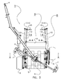
- FIG. 3 shows the wrapper 1 during the loading process.
- the loading arms 12 are moved to the loading position and the grip arms 13 are moved to the closed position, but the loading structure 9 is still in the pick-up position.
- the bale would be enclosed by the loading structure 9.
- the loading arms 12 are arranged substantially parallel to each other.
- the distance between the loading arms 12 is chosen that a bale would be arranged tight-fit between the loading arms 12. This has the advantage that the centre of the bale is aligned with the middle of the wrapping table. This is advantageous in view of the gravity forces exerted on the wrapping table.
- no or less torque is exerted on the wrapping table construction due to misalignment of the bale.
- this position may be corrected by the movement of the loading arms 12 from the receiving position to the loading position. Due to this movement the bale is pushed to a position, wherein the bale is enclosed in a tight-fit manner between the two loading arms 12.
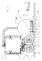
- Figures 4 and 5 show the actual loading of a bale 100 on the wrapping table 5.
- the wrapping table 5 is arranged in a tilted position to facilitate receiving the bale on the wrapping table 5.
- the wrapping table may be moved back to the position shown in Figure 1 to carry out actual wrapping of the bale 100.
- the wrapping table 5 may be tilted in the opposite direction to release the wrapped bale 100 on the ground surface 50.
- FIG 4 shows the wrapper 1 in the same state as Figure 3 , but in side view.
- a bale 100 is arranged on the loading structure 9.
- the bale 100 is enclosed between the loading frame 11, the loading arms 12 in loading position, and the grip arms 13 in the closed position. It will be clear that bales with different diameter sizes can be loaded by the same loading device 8.
- FIG. 5 shows the loading structure 9 in the release position.
- the bale is released from the loading structure 9 on the wrapping table 5.
- This transfer may be completely caused by gravity.
- transfer means may be provided to actively transfer or to guide transfer of the bale from the loading structure 9 to the wrapping table 5.
- the loading structure 9 may be pivoted back to the pick-up position to make rotation of the wrapping means around the bale possible. After wrapping is finished and the wrapped bale is released from the wrapping table 5 a new bale may be loaded by the loading device 8 on the wrapping table 5 for wrapping of this new bale.
- the second section 202 extends from the first section 201 at a greater angle ⁇ 2 with respect to the longitudinal axis I-I (or transport direction X) in the depicted transport position of the wrapper 1.
- the angle ⁇ 2 with respect to the longitudinal axis I-I lies between 30 to 60 degrees, preferably between 40 to 50 degrees in the depicted transport position.
- the first second section 201, 202 of the towbar 200 extend toward the longitudinal axis I-I such that when the wrapper 1 is coupled to a towing vehicle (not shown) the longitudinal axis I-I of the wrapper 1 substantially coincides with a longitudinal axis of the towing vehicle. This has the effect, that the wrapper 1 can be transported in an in-line manner with respect to the towing vehicle by said towing vehicle and that the total width of the combination of the towing vehicle and the wrapper 1 can be kept as small as possible.
Landscapes
- Life Sciences & Earth Sciences (AREA)
- Environmental Sciences (AREA)
- Storage Of Harvested Produce (AREA)
- Packaging Of Special Articles (AREA)
- Basic Packing Technique (AREA)
Applications Claiming Priority (2)
| Application Number | Priority Date | Filing Date | Title |
|---|---|---|---|
| NL1037742A NL1037742C2 (en) | 2010-02-23 | 2010-02-23 | Wrapper for wrapping bales of crop material. |
| EP10803158.4A EP2538765B1 (de) | 2010-02-23 | 2010-12-15 | Wickler zur umwicklung von ballen aus erntegut |
Related Parent Applications (2)
| Application Number | Title | Priority Date | Filing Date |
|---|---|---|---|
| EP10803158.4A Division EP2538765B1 (de) | 2010-02-23 | 2010-12-15 | Wickler zur umwicklung von ballen aus erntegut |
| EP10803158.4A Division-Into EP2538765B1 (de) | 2010-02-23 | 2010-12-15 | Wickler zur umwicklung von ballen aus erntegut |
Publications (3)
| Publication Number | Publication Date |
|---|---|
| EP2721918A2 true EP2721918A2 (de) | 2014-04-23 |
| EP2721918A3 EP2721918A3 (de) | 2014-12-24 |
| EP2721918B1 EP2721918B1 (de) | 2017-02-22 |
Family
ID=42830674
Family Applications (2)
| Application Number | Title | Priority Date | Filing Date |
|---|---|---|---|
| EP13197803.3A Not-in-force EP2721918B1 (de) | 2010-02-23 | 2010-12-15 | Wickler zur Umwicklung von Ballen aus Erntegut |
| EP10803158.4A Not-in-force EP2538765B1 (de) | 2010-02-23 | 2010-12-15 | Wickler zur umwicklung von ballen aus erntegut |
Family Applications After (1)
| Application Number | Title | Priority Date | Filing Date |
|---|---|---|---|
| EP10803158.4A Not-in-force EP2538765B1 (de) | 2010-02-23 | 2010-12-15 | Wickler zur umwicklung von ballen aus erntegut |
Country Status (6)
| Country | Link |
|---|---|
| US (2) | US8578686B2 (de) |
| EP (2) | EP2721918B1 (de) |
| KR (1) | KR20130033357A (de) |
| DK (1) | DK2538765T3 (de) |
| NL (1) | NL1037742C2 (de) |
| WO (1) | WO2011105888A1 (de) |
Families Citing this family (4)
| Publication number | Priority date | Publication date | Assignee | Title |
|---|---|---|---|---|
| US9107346B2 (en) | 2009-05-29 | 2015-08-18 | Lely Patent N.V. | Wrapping device |
| NL1037742C2 (en) * | 2010-02-23 | 2011-08-24 | Forage Innovations Bv | Wrapper for wrapping bales of crop material. |
| US9637255B2 (en) * | 2012-12-26 | 2017-05-02 | The Raymond Corporation | Palletized load wrapping and transporting vehicle and method |
| KR102310914B1 (ko) * | 2021-04-06 | 2021-10-07 | 하명덕 | 베일 구름이 방지되는 랩핑기 |
Citations (1)
| Publication number | Priority date | Publication date | Assignee | Title |
|---|---|---|---|---|
| FI117504B (sv) | 2003-04-24 | 2006-11-15 | Elho Ab Oy | Balinplastare |
Family Cites Families (58)
| Publication number | Priority date | Publication date | Assignee | Title |
|---|---|---|---|---|
| US4019643A (en) * | 1975-07-22 | 1977-04-26 | Chromalloy American Corporation | Hay carrying apparatus |
| US4103794A (en) * | 1976-02-20 | 1978-08-01 | B & K Industries Ltd. | Bale mover |
| EP0110110B1 (de) * | 1982-10-27 | 1988-04-20 | DARIO MANULI S.p.A. | Vorrichtung zum kontinuierlichen und hermetischen Umhüllen eines Körpers, insbesondere eines zylindrischen Heuballens |
| US4578008A (en) * | 1984-04-27 | 1986-03-25 | Gleason Harold T | Hay bale loader |
| DK167043B1 (da) * | 1985-05-30 | 1993-08-23 | Freudendahl J Fab As | Koblingsindretning til sammenkobling af et koerbart markredskab til en traktor |
| US4641484A (en) * | 1985-07-08 | 1987-02-10 | Popelka Frank E | Hay bale wrapping machine |
| US4685282A (en) * | 1985-07-29 | 1987-08-11 | Allen David R | Hay rake assembly |
| US4912911A (en) * | 1986-10-13 | 1990-04-03 | G.D. Engineering Pty. Limited | Machine for stretch wrapping of large reels of paper and other materials |
| US5129215A (en) * | 1990-09-25 | 1992-07-14 | Gratton Robert E | Method and means for wrapping bales of hay |
| GB9302996D0 (en) * | 1993-02-15 | 1993-03-31 | Kverneland Underhaug As | Bale wrapper apparatus |
| US5335856A (en) * | 1992-10-13 | 1994-08-09 | Fmc Corporation | Air boom sprayer trailer hitch and suspension |
| US5483785A (en) * | 1994-06-17 | 1996-01-16 | Dicarlo Machine Corporation | Apparatus for wrapping bales of silage |
| US5822967A (en) * | 1996-06-11 | 1998-10-20 | Vermeer Manufacturing Co. | Baler with swing arm bale wrapper |
| US6000705A (en) * | 1996-09-05 | 1999-12-14 | Wright Mfg., Inc. | Sulky device with triple pivot attachment to mower |
| IES80587B2 (en) * | 1997-07-25 | 1998-10-07 | Comtor Limited | A combined compacting and wrapping machine |
| CA2217075A1 (en) * | 1997-10-01 | 1999-04-01 | Oscar Frey | Bale wrapping machine |
| GB2337245A (en) * | 1998-05-12 | 1999-11-17 | Agri Patents Limited | Bale wrapping apparatus for towing behind baler |
| ATE339085T1 (de) * | 1998-11-11 | 2006-10-15 | Kverneland Naerbo As | Tandem ziehbare kombination |
| US6273446B1 (en) * | 1998-11-13 | 2001-08-14 | Magic Axle Systems Ltd | Steering control system for trailers |
| GB9903741D0 (en) * | 1999-02-19 | 1999-04-14 | Kverneland Underhaug As | Bale handler device for bale wrapper apparatus |
| DE19910555A1 (de) * | 1999-03-10 | 2000-09-14 | Lely Welger Maschinenfabrik Gm | Landwirtschaftliche Rundballenpresse mit einer Wägeeinrichtung |
| US6247291B1 (en) * | 1999-07-21 | 2001-06-19 | New Holland North America, Inc. | Storage apparatus for round baler wrapping material |
| GB9925984D0 (en) * | 1999-11-03 | 2000-01-12 | Kverneland Naerbo As | Bale wrapper apparatus |
| JP3976552B2 (ja) * | 2001-11-19 | 2007-09-19 | 株式会社タカキタ | ロールベーラ |
| DE10240091A1 (de) * | 2002-08-28 | 2004-03-11 | Deere & Company, Moline | Wickelgerät |
| EP1393614A3 (de) * | 2002-08-28 | 2009-06-03 | Deere & Company | Wickelgerät |
| DE10254954A1 (de) * | 2002-11-26 | 2004-06-03 | Deere & Company, Moline | Ballenentladevorrichtung einer Rundballenpresse |
| DE10257252A1 (de) * | 2002-12-07 | 2004-08-12 | Deere & Company, Moline | Presse, insbesondere Rundballenpresse |
| DE10322333A1 (de) * | 2003-05-17 | 2004-12-02 | Deere & Company, Moline | Vorrichtung zur Messung der Gewichtskraft eines Ballens |
| DE10339652B4 (de) * | 2003-08-28 | 2012-09-06 | Deere & Company | Rundballenpresse |
| US20050257513A1 (en) * | 2004-04-01 | 2005-11-24 | Smith Kevin M | Hydraulic bale ramp |
| US20050217233A1 (en) * | 2004-04-01 | 2005-10-06 | Smith Kevin M | Hydraulic bale ramp |
| GB2415177A (en) * | 2004-06-15 | 2005-12-21 | Cnh Belgium Nv | Bale wrapping machine with wrap-retaining arm assembly |
| IES20050548A2 (en) * | 2004-08-18 | 2006-09-06 | William Ian Fallon | A trailer |
| US7197979B2 (en) * | 2005-06-10 | 2007-04-03 | Deere & Company | Controlled bale ejection mechanism |
| GB2444914A (en) * | 2006-12-19 | 2008-06-25 | Cnh Belgium Nv | Improvements in Agricultural Balers |
| US7694491B2 (en) * | 2007-10-30 | 2010-04-13 | Deere & Company | Cotton harvester for producing modules which can be automatically identified and oriented |
| EP2090153B1 (de) * | 2008-02-13 | 2015-09-09 | Usines CLAAS France S.A.S. | Rundballenpresse |
| IES20080391A2 (en) * | 2008-05-19 | 2009-11-25 | Idough Invest Company | A bale wrapping machine |
| ATE514330T1 (de) * | 2008-07-31 | 2011-07-15 | Deere & Co | Ballenpresse und einwicklerkombination |
| PL2229810T3 (pl) * | 2009-03-18 | 2012-12-31 | Deere & Co | Okrągła prasa do belowania z urządzeniem do owijania siatką |
| BE1018759A3 (nl) * | 2009-05-19 | 2011-08-02 | Cnh Belgium Nv | Een rechthoekige balenpers met een verbeterde uitwerpgoot. |
| NL1037002C2 (nl) * | 2009-05-29 | 2010-11-30 | Lely Patent Nv | Centreren van folie. |
| US9560807B2 (en) * | 2009-05-29 | 2017-02-07 | Lely Patent N.V. | Wrapping device and method for wrapping an object |
| NL1037000C2 (en) * | 2009-05-29 | 2010-11-30 | Lely Patent Nv | AGRICULTURAL SYSTEM TO FORM AND WRAP BALES OR CROP MATERIAL. |
| US9107346B2 (en) * | 2009-05-29 | 2015-08-18 | Lely Patent N.V. | Wrapping device |
| NL1037441C2 (en) * | 2009-11-04 | 2011-05-10 | Lely Patent Nv | Agricultural system to form and wrap bales of crop material. |
| BE1019181A3 (nl) * | 2010-02-12 | 2012-04-03 | Cnh Belgium Nv | Vierkantebalenpers en bijbehorende regelmethode. |
| NL1037740C2 (en) * | 2010-02-23 | 2011-08-24 | Forage Innovations Bv | Wrapper for wrapping round bales of crop material. |
| NL1037739C2 (en) * | 2010-02-23 | 2011-08-24 | Forage Innovations Bv | Wrapper for wrapping round bales of crop material. |
| NL1037742C2 (en) * | 2010-02-23 | 2011-08-24 | Forage Innovations Bv | Wrapper for wrapping bales of crop material. |
| US8113113B2 (en) * | 2010-05-04 | 2012-02-14 | Deere & Company | Discharged bale control device and control method |
| EP2608653B1 (de) * | 2010-08-24 | 2018-10-10 | CNH Industrial Belgium nv | Verpackungssystem und -verfahren für grosse baumwoll- oder biomasseballen |
| EP2430904B1 (de) * | 2010-09-16 | 2013-03-13 | Deere & Company | Rundballenpresse mit einer Umhüllungslvorrichtung |
| US20120240795A1 (en) * | 2010-12-28 | 2012-09-27 | Agco Corporation | Roller Bale Chute Accumulation |
| BE1020067A3 (nl) * | 2011-07-11 | 2013-04-02 | Cnh Belgium Nv | Robuust baaluitwerper systeem. |
| BE1020077A3 (nl) * | 2011-07-18 | 2013-04-02 | Cnh Belgium Nv | In lijn liggend baaluitwerpsysteem. |
| US20140261023A1 (en) * | 2013-03-15 | 2014-09-18 | Cnh Industrial America Llc | Bale forming control system and method |
-
2010
- 2010-02-23 NL NL1037742A patent/NL1037742C2/en not_active IP Right Cessation
- 2010-12-15 DK DK10803158.4T patent/DK2538765T3/da active
- 2010-12-15 WO PCT/NL2010/000172 patent/WO2011105888A1/en not_active Ceased
- 2010-12-15 KR KR1020127024783A patent/KR20130033357A/ko not_active Withdrawn
- 2010-12-15 EP EP13197803.3A patent/EP2721918B1/de not_active Not-in-force
- 2010-12-15 EP EP10803158.4A patent/EP2538765B1/de not_active Not-in-force
-
2012
- 2012-08-23 US US13/592,377 patent/US8578686B2/en not_active Expired - Fee Related
-
2013
- 2013-07-10 US US13/938,356 patent/US20130291484A1/en not_active Abandoned
Patent Citations (1)
| Publication number | Priority date | Publication date | Assignee | Title |
|---|---|---|---|---|
| FI117504B (sv) | 2003-04-24 | 2006-11-15 | Elho Ab Oy | Balinplastare |
Also Published As
| Publication number | Publication date |
|---|---|
| EP2721918B1 (de) | 2017-02-22 |
| EP2538765A1 (de) | 2013-01-02 |
| DK2538765T3 (da) | 2014-06-02 |
| US20130291484A1 (en) | 2013-11-07 |
| US20120311970A1 (en) | 2012-12-13 |
| WO2011105888A1 (en) | 2011-09-01 |
| US8578686B2 (en) | 2013-11-12 |
| EP2538765B1 (de) | 2014-02-26 |
| NL1037742C2 (en) | 2011-08-24 |
| EP2721918A3 (de) | 2014-12-24 |
| KR20130033357A (ko) | 2013-04-03 |
Similar Documents
| Publication | Publication Date | Title |
|---|---|---|
| EP2538767B1 (de) | Wickler zur umwicklung von runden ballen aus erntegut | |
| EP2538765B1 (de) | Wickler zur umwicklung von ballen aus erntegut | |
| AU2010253566B2 (en) | Agricultural system to form and wrap bales of crop material | |
| EP2496066B1 (de) | Landwirtschaftliches system zur formung von wickelballen aus erntegut | |
| US9930835B2 (en) | Wrapping device | |
| US9560807B2 (en) | Wrapping device and method for wrapping an object | |
| CN106508300B (zh) | 捆包包装机 | |
| EP3461318B1 (de) | System und verfahren zum rekomprimieren von runden ballen zu quadratischen ballen | |
| WO2011053120A1 (en) | Baling device to form bales of crop material | |
| EP2538766B1 (de) | Wickler zur umwicklung von runden ballen aus erntegut | |
| EP3593622B1 (de) | Verbesserte umwicklungsvorrichtung | |
| EP2434865B1 (de) | Umhüllvorrichtung | |
| EP2434864A1 (de) | Umhüllungseinheit | |
| EP1033072A2 (de) | Ladevorrichtung für Ballenwickler |
Legal Events
| Date | Code | Title | Description |
|---|---|---|---|
| PUAI | Public reference made under article 153(3) epc to a published international application that has entered the european phase |
Free format text: ORIGINAL CODE: 0009012 |
|
| AC | Divisional application: reference to earlier application |
Ref document number: 2538765 Country of ref document: EP Kind code of ref document: P |
|
| AK | Designated contracting states |
Kind code of ref document: A2 Designated state(s): AL AT BE BG CH CY CZ DE DK EE ES FI FR GB GR HR HU IE IS IT LI LT LU LV MC MK MT NL NO PL PT RO RS SE SI SK SM TR |
|
| PUAL | Search report despatched |
Free format text: ORIGINAL CODE: 0009013 |
|
| AK | Designated contracting states |
Kind code of ref document: A3 Designated state(s): AL AT BE BG CH CY CZ DE DK EE ES FI FR GB GR HR HU IE IS IT LI LT LU LV MC MK MT NL NO PL PT RO RS SE SI SK SM TR |
|
| RIC1 | Information provided on ipc code assigned before grant |
Ipc: A01D 87/12 20060101AFI20141114BHEP Ipc: A01F 15/07 20060101ALI20141114BHEP |
|
| 17P | Request for examination filed |
Effective date: 20150624 |
|
| RBV | Designated contracting states (corrected) |
Designated state(s): AL AT BE BG CH CY CZ DE DK EE ES FI FR GB GR HR HU IE IS IT LI LT LU LV MC MK MT NL NO PL PT RO RS SE SI SK SM TR |
|
| GRAP | Despatch of communication of intention to grant a patent |
Free format text: ORIGINAL CODE: EPIDOSNIGR1 |
|
| INTG | Intention to grant announced |
Effective date: 20160816 |
|
| RIN1 | Information on inventor provided before grant (corrected) |
Inventor name: REIJERSEN VAN BUUREN, WILLEM JACOBUS |
|
| STAA | Information on the status of an ep patent application or granted ep patent |
Free format text: STATUS: GRANT OF PATENT IS INTENDED |
|
| GRAS | Grant fee paid |
Free format text: ORIGINAL CODE: EPIDOSNIGR3 |
|
| GRAA | (expected) grant |
Free format text: ORIGINAL CODE: 0009210 |
|
| STAA | Information on the status of an ep patent application or granted ep patent |
Free format text: STATUS: THE PATENT HAS BEEN GRANTED |
|
| AC | Divisional application: reference to earlier application |
Ref document number: 2538765 Country of ref document: EP Kind code of ref document: P |
|
| AK | Designated contracting states |
Kind code of ref document: B1 Designated state(s): AL AT BE BG CH CY CZ DE DK EE ES FI FR GB GR HR HU IE IS IT LI LT LU LV MC MK MT NL NO PL PT RO RS SE SI SK SM TR |
|
| REG | Reference to a national code |
Ref country code: GB Ref legal event code: FG4D |
|
| REG | Reference to a national code |
Ref country code: CH Ref legal event code: EP |
|
| REG | Reference to a national code |
Ref country code: AT Ref legal event code: REF Ref document number: 868556 Country of ref document: AT Kind code of ref document: T Effective date: 20170315 |
|
| REG | Reference to a national code |
Ref country code: IE Ref legal event code: FG4D |
|
| REG | Reference to a national code |
Ref country code: DE Ref legal event code: R096 Ref document number: 602010040291 Country of ref document: DE |
|
| REG | Reference to a national code |
Ref country code: LT Ref legal event code: MG4D |
|
| REG | Reference to a national code |
Ref country code: NL Ref legal event code: MP Effective date: 20170222 |
|
| REG | Reference to a national code |
Ref country code: AT Ref legal event code: MK05 Ref document number: 868556 Country of ref document: AT Kind code of ref document: T Effective date: 20170222 |
|
| PG25 | Lapsed in a contracting state [announced via postgrant information from national office to epo] |
Ref country code: NO Free format text: LAPSE BECAUSE OF FAILURE TO SUBMIT A TRANSLATION OF THE DESCRIPTION OR TO PAY THE FEE WITHIN THE PRESCRIBED TIME-LIMIT Effective date: 20170522 Ref country code: GR Free format text: LAPSE BECAUSE OF FAILURE TO SUBMIT A TRANSLATION OF THE DESCRIPTION OR TO PAY THE FEE WITHIN THE PRESCRIBED TIME-LIMIT Effective date: 20170523 Ref country code: HR Free format text: LAPSE BECAUSE OF FAILURE TO SUBMIT A TRANSLATION OF THE DESCRIPTION OR TO PAY THE FEE WITHIN THE PRESCRIBED TIME-LIMIT Effective date: 20170222 Ref country code: FI Free format text: LAPSE BECAUSE OF FAILURE TO SUBMIT A TRANSLATION OF THE DESCRIPTION OR TO PAY THE FEE WITHIN THE PRESCRIBED TIME-LIMIT Effective date: 20170222 Ref country code: LT Free format text: LAPSE BECAUSE OF FAILURE TO SUBMIT A TRANSLATION OF THE DESCRIPTION OR TO PAY THE FEE WITHIN THE PRESCRIBED TIME-LIMIT Effective date: 20170222 |
|
| PG25 | Lapsed in a contracting state [announced via postgrant information from national office to epo] |
Ref country code: PT Free format text: LAPSE BECAUSE OF FAILURE TO SUBMIT A TRANSLATION OF THE DESCRIPTION OR TO PAY THE FEE WITHIN THE PRESCRIBED TIME-LIMIT Effective date: 20170622 Ref country code: ES Free format text: LAPSE BECAUSE OF FAILURE TO SUBMIT A TRANSLATION OF THE DESCRIPTION OR TO PAY THE FEE WITHIN THE PRESCRIBED TIME-LIMIT Effective date: 20170222 Ref country code: SE Free format text: LAPSE BECAUSE OF FAILURE TO SUBMIT A TRANSLATION OF THE DESCRIPTION OR TO PAY THE FEE WITHIN THE PRESCRIBED TIME-LIMIT Effective date: 20170222 Ref country code: LV Free format text: LAPSE BECAUSE OF FAILURE TO SUBMIT A TRANSLATION OF THE DESCRIPTION OR TO PAY THE FEE WITHIN THE PRESCRIBED TIME-LIMIT Effective date: 20170222 Ref country code: NL Free format text: LAPSE BECAUSE OF FAILURE TO SUBMIT A TRANSLATION OF THE DESCRIPTION OR TO PAY THE FEE WITHIN THE PRESCRIBED TIME-LIMIT Effective date: 20170222 Ref country code: BG Free format text: LAPSE BECAUSE OF FAILURE TO SUBMIT A TRANSLATION OF THE DESCRIPTION OR TO PAY THE FEE WITHIN THE PRESCRIBED TIME-LIMIT Effective date: 20170522 Ref country code: AT Free format text: LAPSE BECAUSE OF FAILURE TO SUBMIT A TRANSLATION OF THE DESCRIPTION OR TO PAY THE FEE WITHIN THE PRESCRIBED TIME-LIMIT Effective date: 20170222 Ref country code: RS Free format text: LAPSE BECAUSE OF FAILURE TO SUBMIT A TRANSLATION OF THE DESCRIPTION OR TO PAY THE FEE WITHIN THE PRESCRIBED TIME-LIMIT Effective date: 20170222 |
|
| PG25 | Lapsed in a contracting state [announced via postgrant information from national office to epo] |
Ref country code: CZ Free format text: LAPSE BECAUSE OF FAILURE TO SUBMIT A TRANSLATION OF THE DESCRIPTION OR TO PAY THE FEE WITHIN THE PRESCRIBED TIME-LIMIT Effective date: 20170222 Ref country code: EE Free format text: LAPSE BECAUSE OF FAILURE TO SUBMIT A TRANSLATION OF THE DESCRIPTION OR TO PAY THE FEE WITHIN THE PRESCRIBED TIME-LIMIT Effective date: 20170222 Ref country code: SK Free format text: LAPSE BECAUSE OF FAILURE TO SUBMIT A TRANSLATION OF THE DESCRIPTION OR TO PAY THE FEE WITHIN THE PRESCRIBED TIME-LIMIT Effective date: 20170222 Ref country code: IT Free format text: LAPSE BECAUSE OF FAILURE TO SUBMIT A TRANSLATION OF THE DESCRIPTION OR TO PAY THE FEE WITHIN THE PRESCRIBED TIME-LIMIT Effective date: 20170222 Ref country code: RO Free format text: LAPSE BECAUSE OF FAILURE TO SUBMIT A TRANSLATION OF THE DESCRIPTION OR TO PAY THE FEE WITHIN THE PRESCRIBED TIME-LIMIT Effective date: 20170222 |
|
| REG | Reference to a national code |
Ref country code: DE Ref legal event code: R097 Ref document number: 602010040291 Country of ref document: DE |
|
| PG25 | Lapsed in a contracting state [announced via postgrant information from national office to epo] |
Ref country code: DK Free format text: LAPSE BECAUSE OF FAILURE TO SUBMIT A TRANSLATION OF THE DESCRIPTION OR TO PAY THE FEE WITHIN THE PRESCRIBED TIME-LIMIT Effective date: 20170222 Ref country code: PL Free format text: LAPSE BECAUSE OF FAILURE TO SUBMIT A TRANSLATION OF THE DESCRIPTION OR TO PAY THE FEE WITHIN THE PRESCRIBED TIME-LIMIT Effective date: 20170222 Ref country code: SM Free format text: LAPSE BECAUSE OF FAILURE TO SUBMIT A TRANSLATION OF THE DESCRIPTION OR TO PAY THE FEE WITHIN THE PRESCRIBED TIME-LIMIT Effective date: 20170222 |
|
| REG | Reference to a national code |
Ref country code: FR Ref legal event code: PLFP Year of fee payment: 8 |
|
| PLBE | No opposition filed within time limit |
Free format text: ORIGINAL CODE: 0009261 |
|
| STAA | Information on the status of an ep patent application or granted ep patent |
Free format text: STATUS: NO OPPOSITION FILED WITHIN TIME LIMIT |
|
| 26N | No opposition filed |
Effective date: 20171123 |
|
| PG25 | Lapsed in a contracting state [announced via postgrant information from national office to epo] |
Ref country code: SI Free format text: LAPSE BECAUSE OF FAILURE TO SUBMIT A TRANSLATION OF THE DESCRIPTION OR TO PAY THE FEE WITHIN THE PRESCRIBED TIME-LIMIT Effective date: 20170222 |
|
| REG | Reference to a national code |
Ref country code: DE Ref legal event code: R081 Ref document number: 602010040291 Country of ref document: DE Owner name: FORAGE COMPANY B.V., NL Free format text: FORMER OWNER: FORAGE INNOVATIONS B.V., MAASSLUIS, NL |
|
| REG | Reference to a national code |
Ref country code: CH Ref legal event code: PL |
|
| PG25 | Lapsed in a contracting state [announced via postgrant information from national office to epo] |
Ref country code: LU Free format text: LAPSE BECAUSE OF NON-PAYMENT OF DUE FEES Effective date: 20171215 Ref country code: MT Free format text: LAPSE BECAUSE OF NON-PAYMENT OF DUE FEES Effective date: 20171215 |
|
| REG | Reference to a national code |
Ref country code: BE Ref legal event code: MM Effective date: 20171231 |
|
| PG25 | Lapsed in a contracting state [announced via postgrant information from national office to epo] |
Ref country code: CH Free format text: LAPSE BECAUSE OF NON-PAYMENT OF DUE FEES Effective date: 20171231 Ref country code: BE Free format text: LAPSE BECAUSE OF NON-PAYMENT OF DUE FEES Effective date: 20171231 Ref country code: LI Free format text: LAPSE BECAUSE OF NON-PAYMENT OF DUE FEES Effective date: 20171231 |
|
| PG25 | Lapsed in a contracting state [announced via postgrant information from national office to epo] |
Ref country code: HU Free format text: LAPSE BECAUSE OF FAILURE TO SUBMIT A TRANSLATION OF THE DESCRIPTION OR TO PAY THE FEE WITHIN THE PRESCRIBED TIME-LIMIT; INVALID AB INITIO Effective date: 20101215 Ref country code: MC Free format text: LAPSE BECAUSE OF FAILURE TO SUBMIT A TRANSLATION OF THE DESCRIPTION OR TO PAY THE FEE WITHIN THE PRESCRIBED TIME-LIMIT Effective date: 20170222 |
|
| PG25 | Lapsed in a contracting state [announced via postgrant information from national office to epo] |
Ref country code: CY Free format text: LAPSE BECAUSE OF NON-PAYMENT OF DUE FEES Effective date: 20170222 |
|
| PG25 | Lapsed in a contracting state [announced via postgrant information from national office to epo] |
Ref country code: MK Free format text: LAPSE BECAUSE OF FAILURE TO SUBMIT A TRANSLATION OF THE DESCRIPTION OR TO PAY THE FEE WITHIN THE PRESCRIBED TIME-LIMIT Effective date: 20170222 |
|
| PG25 | Lapsed in a contracting state [announced via postgrant information from national office to epo] |
Ref country code: TR Free format text: LAPSE BECAUSE OF FAILURE TO SUBMIT A TRANSLATION OF THE DESCRIPTION OR TO PAY THE FEE WITHIN THE PRESCRIBED TIME-LIMIT Effective date: 20170222 |
|
| PGFP | Annual fee paid to national office [announced via postgrant information from national office to epo] |
Ref country code: GB Payment date: 20191220 Year of fee payment: 10 |
|
| PG25 | Lapsed in a contracting state [announced via postgrant information from national office to epo] |
Ref country code: AL Free format text: LAPSE BECAUSE OF FAILURE TO SUBMIT A TRANSLATION OF THE DESCRIPTION OR TO PAY THE FEE WITHIN THE PRESCRIBED TIME-LIMIT Effective date: 20170222 Ref country code: IS Free format text: LAPSE BECAUSE OF FAILURE TO SUBMIT A TRANSLATION OF THE DESCRIPTION OR TO PAY THE FEE WITHIN THE PRESCRIBED TIME-LIMIT Effective date: 20170622 |
|
| GBPC | Gb: european patent ceased through non-payment of renewal fee |
Effective date: 20201215 |
|
| PG25 | Lapsed in a contracting state [announced via postgrant information from national office to epo] |
Ref country code: GB Free format text: LAPSE BECAUSE OF NON-PAYMENT OF DUE FEES Effective date: 20201215 |
|
| PGFP | Annual fee paid to national office [announced via postgrant information from national office to epo] |
Ref country code: IE Payment date: 20211222 Year of fee payment: 12 |
|
| PG25 | Lapsed in a contracting state [announced via postgrant information from national office to epo] |
Ref country code: IE Free format text: LAPSE BECAUSE OF NON-PAYMENT OF DUE FEES Effective date: 20221215 |
|
| PGFP | Annual fee paid to national office [announced via postgrant information from national office to epo] |
Ref country code: FR Payment date: 20231221 Year of fee payment: 14 Ref country code: DE Payment date: 20231214 Year of fee payment: 14 |
|
| REG | Reference to a national code |
Ref country code: DE Ref legal event code: R119 Ref document number: 602010040291 Country of ref document: DE |
|
| PG25 | Lapsed in a contracting state [announced via postgrant information from national office to epo] |
Ref country code: DE Free format text: LAPSE BECAUSE OF NON-PAYMENT OF DUE FEES Effective date: 20250701 |
|
| PG25 | Lapsed in a contracting state [announced via postgrant information from national office to epo] |
Ref country code: FR Free format text: LAPSE BECAUSE OF NON-PAYMENT OF DUE FEES Effective date: 20241231 |