EP2721458B1 - Vorrichtung und verfahren zum ersetzen einer batterie in einem tragbaren endgerät - Google Patents
Vorrichtung und verfahren zum ersetzen einer batterie in einem tragbaren endgerät Download PDFInfo
- Publication number
- EP2721458B1 EP2721458B1 EP12799888.8A EP12799888A EP2721458B1 EP 2721458 B1 EP2721458 B1 EP 2721458B1 EP 12799888 A EP12799888 A EP 12799888A EP 2721458 B1 EP2721458 B1 EP 2721458B1
- Authority
- EP
- European Patent Office
- Prior art keywords
- portable terminal
- battery
- service
- main battery
- controller
- Prior art date
- Legal status (The legal status is an assumption and is not a legal conclusion. Google has not performed a legal analysis and makes no representation as to the accuracy of the status listed.)
- Not-in-force
Links
Images


Classifications
-
- H—ELECTRICITY
- H04—ELECTRIC COMMUNICATION TECHNIQUE
- H04B—TRANSMISSION
- H04B1/00—Details of transmission systems, not covered by a single one of groups H04B3/00 - H04B13/00; Details of transmission systems not characterised by the medium used for transmission
- H04B1/38—Transceivers, i.e. devices in which transmitter and receiver form a structural unit and in which at least one part is used for functions of transmitting and receiving
- H04B1/40—Circuits
-
- G—PHYSICS
- G06—COMPUTING OR CALCULATING; COUNTING
- G06F—ELECTRIC DIGITAL DATA PROCESSING
- G06F1/00—Details not covered by groups G06F3/00 - G06F13/00 and G06F21/00
- G06F1/26—Power supply means, e.g. regulation thereof
- G06F1/263—Arrangements for using multiple switchable power supplies, e.g. battery and AC
-
- G—PHYSICS
- G06—COMPUTING OR CALCULATING; COUNTING
- G06F—ELECTRIC DIGITAL DATA PROCESSING
- G06F1/00—Details not covered by groups G06F3/00 - G06F13/00 and G06F21/00
- G06F1/26—Power supply means, e.g. regulation thereof
-
- G—PHYSICS
- G06—COMPUTING OR CALCULATING; COUNTING
- G06F—ELECTRIC DIGITAL DATA PROCESSING
- G06F1/00—Details not covered by groups G06F3/00 - G06F13/00 and G06F21/00
- G06F1/26—Power supply means, e.g. regulation thereof
- G06F1/32—Means for saving power
- G06F1/3203—Power management, i.e. event-based initiation of a power-saving mode
- G06F1/3206—Monitoring of events, devices or parameters that trigger a change in power modality
-
- H—ELECTRICITY
- H02—GENERATION; CONVERSION OR DISTRIBUTION OF ELECTRIC POWER
- H02J—ELECTRIC POWER NETWORKS; CIRCUIT ARRANGEMENTS OR SYSTEMS FOR SUPPLYING OR DISTRIBUTING ELECTRIC POWER; SYSTEMS FOR STORING ELECTRIC ENERGY
- H02J9/00—Circuit arrangements for emergency or stand-by power supply, e.g. for emergency lighting
- H02J9/04—Circuit arrangements for emergency or stand-by power supply, e.g. for emergency lighting in which the distribution system is disconnected from the normal source and connected to a standby source
- H02J9/06—Circuit arrangements for emergency or stand-by power supply, e.g. for emergency lighting in which the distribution system is disconnected from the normal source and connected to a standby source with automatic change-over, e.g. UPS systems
-
- Y—GENERAL TAGGING OF NEW TECHNOLOGICAL DEVELOPMENTS; GENERAL TAGGING OF CROSS-SECTIONAL TECHNOLOGIES SPANNING OVER SEVERAL SECTIONS OF THE IPC; TECHNICAL SUBJECTS COVERED BY FORMER USPC CROSS-REFERENCE ART COLLECTIONS [XRACs] AND DIGESTS
- Y02—TECHNOLOGIES OR APPLICATIONS FOR MITIGATION OR ADAPTATION AGAINST CLIMATE CHANGE
- Y02B—CLIMATE CHANGE MITIGATION TECHNOLOGIES RELATED TO BUILDINGS, e.g. HOUSING, HOUSE APPLIANCES OR RELATED END-USER APPLICATIONS
- Y02B70/00—Technologies for an efficient end-user side electric power management and consumption
- Y02B70/30—Systems integrating technologies related to power network operation and communication or information technologies for improving the carbon footprint of the management of residential or tertiary loads, i.e. smart grids as climate change mitigation technology in the buildings sector, including also the last stages of power distribution and the control, monitoring or operating management systems at local level
-
- Y—GENERAL TAGGING OF NEW TECHNOLOGICAL DEVELOPMENTS; GENERAL TAGGING OF CROSS-SECTIONAL TECHNOLOGIES SPANNING OVER SEVERAL SECTIONS OF THE IPC; TECHNICAL SUBJECTS COVERED BY FORMER USPC CROSS-REFERENCE ART COLLECTIONS [XRACs] AND DIGESTS
- Y04—INFORMATION OR COMMUNICATION TECHNOLOGIES HAVING AN IMPACT ON OTHER TECHNOLOGY AREAS
- Y04S—SYSTEMS INTEGRATING TECHNOLOGIES RELATED TO POWER NETWORK OPERATION, COMMUNICATION OR INFORMATION TECHNOLOGIES FOR IMPROVING THE ELECTRICAL POWER GENERATION, TRANSMISSION, DISTRIBUTION, MANAGEMENT OR USAGE, i.e. SMART GRIDS
- Y04S20/00—Management or operation of end-user stationary applications or the last stages of power distribution; Controlling, monitoring or operating thereof
- Y04S20/20—End-user application control systems
Definitions
- Another aspect of embodiments of the present invention is to provide a method and apparatus for continuously providing a specific service even though a battery is replaced during the specific service in progress in a portable terminal.
- a portable terminal comprising a main battery, an auxiliary battery, a cover removal sensor configured to sense a removal of a battery cover, and a controller.
- the controller is configured, in response to the battery cover removal, to switch from the main battery to the auxiliary battery for supplying a power
- the auxiliary battery is configured to supply the power to some components of the portable terminal under the control of the controller
- the cover removal sensor is configured to generate a cover removal notification signal when the removal of the battery cover is sensed
- the controller is configured to transmit, during a call service between the portable terminal and a further terminal through a base station, a standby mode transition request to the base station requesting transitioning of the portable terminal from a call mode to a standby mode in which a call connection between the portable terminal and the base station is released while a call connection between the base station and the further terminal is maintained, upon receipt of the cover removal notification signal, and wherein the controller is configured to transmit, during the standby mode,
- the cover removal sensor 105 is provided on a cover covering the main battery 109 or on a bottom plate of the cover. Upon sensing a removal of the cover, the cover removal sensor 105 outputs a cover removal notification signal to the controller 101, indicating the removal of the cover.
- the cover removal sensor 105 may include a switch, an optical sensor, or a touch sensor.
- the display 119 may be configured with a Liquid Crystal Display (LCD) or an Organic Light Emitting Diode (OLED) (e.g. a Passive-Matrix OLED (PMOLED) or Active-Matrix OLED (AMOLED)).
- the display 119 outputs various types of display information generated in the portable terminal.
- the display 119 may include a capacitive or resistive touch screen, to thereby serve as an input unit for controlling the portable terminal, along with the keypad 113.
- the power manager 107 controls charging of the main battery 109 with power (e.g. a charging current value) received through a Travel Adapter (TA) or a Universal Serial Bus (USB) cable and supplies power received from the main battery 109 or the auxiliary battery 111 to each component of the portable terminal.
- the power manager 107 may also output information about the charged state and temperature of the main battery 109 to the controller 101.
- the power manager 107 switches a power supply source from the main battery 109 to the auxiliary battery 111 or from the auxiliary battery 111 to the main battery 109 under the control of the controller 101.
- the power manager 107 periodically measures the voltage of the main battery 109 and outputs the voltage measurement to the controller 101.
- the power manager 107 may be incorporated into the controller 101.
- the controller 101 provides overall control to the portable terminal.
- the controller 101 may switch and control an operation of the portable terminal according to a user input received through the keypad 113 or the display 119.
- the controller 101 transitions the portable terminal from a current operation mode to sleep mode and outputs a battery switch signal to the power manager 107, commanding switching of a power supply source from the main battery 109 to the auxiliary battery 111.
- the sleep mode is a mode that minimizes the power consumption of the portable terminal, and the controller 101 may maintain the sleep mode for about 30 minutes by receiving power from the auxiliary battery 111.
- GPS Global Positioning System
- FIG. 2 is a flowchart illustrating an operation for replacing a battery in the portable terminal according to an embodiment of the present invention.
- the controller 101 executes a service selected by a user or a service scheduled to be executed at a predetermined time in step 201.
- the service refers to any service that can be provided by the portable terminal.
- the service may be an application, a camera service, a DMB service, a call service, a communication service through a 3G network or Wi-Fi, a video play service, a sound source play service, or a game service, which is provided in the portable terminal.
- step 207 the controller 101 determines whether the main battery 109 has been replaced. If the controller 101 determines that the main battery 109 has been replaced, the controller 101 goes to step 209. On the other hand, if the controller 101 determines that the main battery 109 has not been replaced for a predetermined time period, the controller 101 goes to step 213.
- the controller 101 may monitor whether the main battery 109 has been replaced or not based on the voltage of the main battery 109 periodically output from the power manager 107.
- the predetermined time period is a time sufficient for the user to replace the main battery 109, within a range from 10 seconds to 30 seconds.
- the controller 101 may determine that the main battery 109 has been replaced. On the other hand, if the voltage of the main battery 109 is maintained to be 0V for a predetermined time period, the controller 101 determines that the main battery 109 has not been replaced.
- the controller 101 retrieves the service history from the memory 103 and resumes the service executed before the battery replacement using the service history in step 211.
- the service history includes a name of the service and a process of the service.
- the controller 101 stores the service history including a name of the internet application and a web site address in respect to the web surfing.
- BS Base Station
- step 327 the first portable terminal 301 powers off itself.
- the first portable terminal 301 transmits a call mode transition request message to the BS 303, requesting transitioning of the standby mode to the call mode between the first and second portable terminals 301 and 305 in step 323.
- step 325 the BS 303 reconnects the call between the first and second portable terminals 305, thus re-establishing the call connection between them.
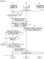
- FIG. 4 is a flowchart illustrating an operation of the portable terminal for replacing the battery according to the embodiment of the present invention illustrated in FIG. 3
- the first portable terminal 301 establishes a call connection with the second portable terminal 305 through the BS 303 in step 401 and determines whether the cover has been removed from the main battery 109 in step 403. If the cover has been removed, the first portable terminal 301 proceeds to step 405 and otherwise, the portable terminal 301 repeats step 403.
- step 405 the first portable terminal 301 transmits a standby mode transition request message to the BS 303, requesting transitioning of the call mode to the standby mode between the first and second portable terminals 301 and 305 and releases the call connection from the BS 303.
- step 407 the first portable terminal 301 transitions to the sleep mode and switches the power supply source from the main battery 109 to the auxiliary battery 111.
- step 409 the first portable terminal 301 determines whether the main battery 109 has been replaced. If the first portable terminal 301 determines that the main battery 109 has been replaced, the first portable terminal 301 goes to step 411. On the other hand, if the first portable terminal 301 determines that the main battery 109 has not been replaced for a predetermined time period, the first portable terminal 301 goes to step 415.
- step 415 the first portable terminal 301 powers off itself.
- the first portable terminal 301 switches the power supply source from the auxiliary battery 111 to the main battery 109 and transitions from the sleep mode to the active mode in step 411.
- the first portable terminal 301 performs steps 401 to 415 in this manner, it can allow for replacement of the main battery 109 without power-off during a call with the second portable terminal.
- the first portable terminal 301 reconnects the call to the second portable terminal 305 as soon as the main battery 109 has been completely replaced, the replacement of the main battery 109 is possible, without terminating the call service.
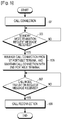
- FIG. 5 is a flowchart illustrating an operation of the BS for reconnecting a call after the battery of the portable terminal is replaced according to the embodiment of the present invention illustrated in FIG. 3 .
- the BS 303 establishes a call connection between the first and second portable terminals 301 and 305 in step 501 and determines whether a standby mode transition request message has been received from the first portable terminal 301 in step 503. Upon receipt of the standby mode transition request message, the BS 303 proceeds to step 505 and otherwise, the BS 303 repeats step 503.
- step 505 the BS 303 releases the call connection from the first portable terminal 301, while maintaining the call connection with the second portable terminal 305 from which the call connection to the first portable terminal 301 has been released.
- the BS 303 determines whether a call mode transition request message has been received from the first portable terminal 301 in step 507. Upon receipt of the call mode transition request message, the BS 303 proceeds to step 509 and otherwise, the BS 303 repeats step 507.
- step 509 the BS 303 reconnects the call between the first and second portable terminals 301 and 305, thus re-establishing the call connection between them.
- the BS 303 maintains the call connection with the second portable terminal 305 for a predetermined time period. If the call mode transition request message has not been received from the first portable terminal 301 for the predetermined time period, the BS 303 may release the call connection from the second portable terminal 305.
- the predetermined time period represents a duration sufficient for replacing the main battery 109. For example, the predetermined time period may be within a range from 10 seconds to 30 seconds.
- the service history of a specific service being executed before the battery replacement is stored so that the specific service may continue in spite of the battery replacement of the portable terminal.
Landscapes
- Engineering & Computer Science (AREA)
- Theoretical Computer Science (AREA)
- General Engineering & Computer Science (AREA)
- General Physics & Mathematics (AREA)
- Physics & Mathematics (AREA)
- Power Engineering (AREA)
- Business, Economics & Management (AREA)
- Emergency Management (AREA)
- Computer Networks & Wireless Communication (AREA)
- Signal Processing (AREA)
- Telephone Function (AREA)
- Mobile Radio Communication Systems (AREA)
- Battery Mounting, Suspending (AREA)
- Charge And Discharge Circuits For Batteries Or The Like (AREA)
Claims (12)
- Tragbares Endgerät, das Folgendes umfasst:eine Hauptbatterie (109);eine Hilfsbatterie (111);einen Abdeckungsentfernungssensor (105), der dafür konfiguriert ist, eine Entfernung einer Batterieabdeckung zu erfassen; undeine Steuerheit (101), die als Reaktion auf das Entfernen der Batterieabdeckung dafür konfiguriert ist, von der Hauptbatterie (109) zur Hilfsbatterie (111) zu schalten, um Energie zuzuführen,wobei die Hilfsbatterie (111) dafür konfiguriert ist, einige Komponenten des tragbaren Endgeräts unter der Steuerung der Steuereinheit (101) mit Strom zu versorgen, und wobei der Abdeckungsentfernungssensor (105) dafür konfiguriert ist, ein Abdeckungsentfernungsbenachrichtigungssignal zu erzeugen, wenn das Entfernen der Batterieabdeckung erfasst wird, und wobei die Steuereinheit (101) dafür konfiguriert ist, während eines Anrufdienstes zwischen dem tragbaren Endgerät und einem weiteren Endgerät durch eine Basisstation (303) eine Bereitschaftsmodus-Übergangsanforderung an die Basisstation (303) zu senden, die den Übergang des tragbaren Endgeräts von einem Anrufmodus in einen Bereitschaftsmodus anfrordert, bei dem eine Anrufverbindung zwischen dem tragbaren Endgerät und der Basisstation (303) aufgehoben wird, während eine Anrufverbindung zwischen der Basisstation und dem weiteren Endgerät nach Empfang des Abdeckungsentfernungsbenachrichtigungssignals aufrechterhalten wird, und wobei die Steuereinheit dafür konfiguriert ist, während des Bereitschaftsmodus eine Anrufübergangs-anforderung an die Basisstation zu senden, die den Übergang des tragbaren Endgeräts von dem Bereitschaftsmodus in einen Anrufmodus anfordert, in dem eine Anrufverbindung zwischen dem tragbaren Endgerät und der Basisstation (303) wieder hergestellt wird, sobald die Hauptbatterie ersetzt wurde.
- Tragbares Endgerät nach Anspruch 1, wobei die Steuereinheit (101) dafür konfiguriert ist, das tragbare Endgerät als Reaktion auf das Entfernen der Batterieabdeckung von einem aktuellen Betriebsmodus in einen Schlafmodus überzuführen.
- Tragbares Endgerät nach Anspruch 1, wobei die Steuereinheit (101) dafür konfiguriert ist, zu bestimmen, ob die Hauptbatterie (109) innerhalb einer vorbestimmten Zeitspanne ausgetauscht worden ist,
wobei die vorbestimmte Zeitspanne eine Zeit ist, die zum Ersetzen der Hauptbatterie (109) ausreicht. - Tragbares Endgerät nach Anspruch 3, wobei die Steuereinheit (101) dafür konfiguriert ist, die Stromversorgungsquelle zurück zu der Hauptbatterie (109) zu schalten, wenn die Hauptbatterie (109) ausgewechselt wurde, und das tragbare Endgerät von dem Schlafmodus in einen aktiven Modus übergeht.
- Tragbares Endgerät nach Anspruch 1, wobei die Steuereinheit (101) dafür konfiguriert ist, kontinuierlich einen Dienst bereitzustellen, der vor dem Batteriewechsel für den Benutzer und nach dem Umschalten auf die Hilfsbatterie (111) ausgeführt wird.
- Tragbares Endgerät nach Anspruch 5, wobei es sich bei dem Dienst mindestens um einen Anrufdienst, einen Musikwiedergabedienst, einen Videoabspieldienst, einen Kommunikationsdienst oder einen Spieldienst handelt.
- Verfahren zum Ersetzen einer Batterie in einem tragbaren Endgerät, das Folgendes umfasst:Erfassen (203, 309, 403) einer Entfernung einer Batterieabdeckung;als Reaktion auf das Entfernen der Batterieabdeckung Umschalten (205, 317, 407) von einer Hauptbatterie (109) zu einer Hilfsbatterie (111) zum Zuführen einer Energie;wobei die Hilfsbatterie (111) den Strom zu einigen Komponenten des tragbaren Endgeräts unter der Steuerung einer Steuereinheit (101) zuführt, und wobei das Erfassen des Entfernens der Batterieabdeckung ein Erzeugen eines Abdeckungsentfernungsbenachrichtigungssignals umfasst, wenn das Entfernen der Batterieabdeckung erfasst wird, und wobei das Verfahren ferner Folgendes umfasst:
Übertragen (311) während eines Anrufdienstes zwischen dem tragbaren Endgerät und einem weiteren Endgerät durch eine Basisstation (303) einer Bereitschaftsmodus-Übergangsanforderung an die Basisstation (303) umfasst, die den Übergang des tragbaren Endgeräts in einen Bereitschaftsmodus anfordert, in dem eine Anrufverbindung zwischen dem tragbaren Endgerät und der Basisstation (303) freigegeben wird, während eine Anrufverbindung zwischen der Basisstation (303) und dem weiteren Endgerät als Reaktion auf den Empfang des Abdeckungsentfernungsbenachrichtigungssignals aufrechterhalten wird, und wobei das Verfahren ferner Folgendes umfasst:
Übertragen einer Anrufübergangsanforderung an die Basisstation (303) während des Bereitschaftsmodus umfasst, die den Übergang des tragbaren Endgeräts von dem Bereitschaftsmodus in einen Anrufmodus anfordert, in dem eine Anrufverbindung zwischen dem tragbaren Endgerät und der Basisstation (303) wieder hergestellt wird, sobald die Hauptbatterie ersetzt wurde. - Verfahren nach Anspruch 7, wobei das Umschalten (205, 317, 407) von der Hauptbatterie (109) zu der Hilfsbatterie (111) zum Zuführen der Energie das Überführen des tragbaren Endgeräts von einem aktuellen Betriebsmodus in einen Schlafmodus als Reaktion auf das Entfernen der Batterieabdeckung umfasst.
- Verfahren nach Anspruch 7, wobei das Umschalten (205, 317, 407) von der Hauptbatterie (109) zu der Hilfsbatterie (111) zum Zuführen der Energie das Bestimmen umfasst, ob die Hauptbatterie (109) innerhalb einer vorbestimmten Zeitperiode ausgetauscht worden ist,
wobei die vorbestimmte Zeitspanne eine Zeit ist, die zum Ersetzen der Hauptbatterie (109) ausreicht. - Verfahren nach Anspruch 9, das ferner Folgendes umfasst:Umschalten (321, 411) der Energieversorgungsquelle zurück zu der Hauptbatterie (109), wenn die Hauptbatterie (109) ersetzt worden ist; undÜberführen des tragbaren Endgeräts aus dem Schlafmodus in einen aktiven Modus.
- Verfahren nach Anspruch 7, das ferner das kontinuierliche Bereitstellen eines Dienstes umfasst, der vor dem Batteriewechsel für den Benutzer und nach dem Umschalten auf die Hilfsbatterie ausgeführt wird.
- Verfahren nach Anspruch 10, wobei es sich bei dem Dienst mindestens um einen Anrufdienst, einen Musikwiedergabedienst, einen Videoabspieldienst, einen Kommunikationsdienst oder einen Spieldienst handelt.
Applications Claiming Priority (2)
| Application Number | Priority Date | Filing Date | Title |
|---|---|---|---|
| KR1020110057684A KR101843983B1 (ko) | 2011-06-14 | 2011-06-14 | 휴대 단말기에서 배터리를 교체하는 장치 및 방법 |
| PCT/KR2012/004696 WO2012173406A2 (en) | 2011-06-14 | 2012-06-14 | Apparatus and method for replacing a battery in a portable terminal |
Publications (3)
| Publication Number | Publication Date |
|---|---|
| EP2721458A2 EP2721458A2 (de) | 2014-04-23 |
| EP2721458A4 EP2721458A4 (de) | 2015-11-11 |
| EP2721458B1 true EP2721458B1 (de) | 2018-05-30 |
Family
ID=47354058
Family Applications (1)
| Application Number | Title | Priority Date | Filing Date |
|---|---|---|---|
| EP12799888.8A Not-in-force EP2721458B1 (de) | 2011-06-14 | 2012-06-14 | Vorrichtung und verfahren zum ersetzen einer batterie in einem tragbaren endgerät |
Country Status (6)
| Country | Link |
|---|---|
| US (2) | US8660619B2 (de) |
| EP (1) | EP2721458B1 (de) |
| JP (1) | JP2014519790A (de) |
| KR (1) | KR101843983B1 (de) |
| CN (1) | CN103748528B (de) |
| WO (1) | WO2012173406A2 (de) |
Families Citing this family (20)
| Publication number | Priority date | Publication date | Assignee | Title |
|---|---|---|---|---|
| KR101843983B1 (ko) * | 2011-06-14 | 2018-03-30 | 삼성전자주식회사 | 휴대 단말기에서 배터리를 교체하는 장치 및 방법 |
| JP5988142B2 (ja) * | 2011-07-08 | 2016-09-07 | パナソニックIpマネジメント株式会社 | 情報処理装置および情報処理装置の制御方法 |
| CN103142315B (zh) * | 2013-04-01 | 2014-11-05 | 深圳市理邦精密仪器股份有限公司 | 一种具有无线及有线模式的监护探头及其模式切换方法 |
| KR101475332B1 (ko) * | 2014-03-05 | 2014-12-22 | 장보배로 | 보조배터리가 구비된 휴대단말기 |
| KR101442587B1 (ko) * | 2014-04-28 | 2014-09-22 | 최수선 | 배터리 교체 시 전원 유지 기능을 가지는 휴대용 전자기기 |
| CN104248455B (zh) * | 2014-08-20 | 2016-04-27 | 深圳市理邦精密仪器股份有限公司 | 多床位胎儿监护仪的无线传感器管理控制方法及系统 |
| US9857863B2 (en) * | 2014-10-20 | 2018-01-02 | Seiko Epson Corporation | Display apparatus, control method for display apparatus, and program that can switch an operation mode of a display apparatus from a normal operation mode to a battery replacement mode |
| KR102296909B1 (ko) | 2015-01-09 | 2021-09-01 | 삼성전자주식회사 | 보조 배터리를 내장한 전자장치 및 보조 배터리 충전 방법 |
| WO2016114342A1 (ja) * | 2015-01-15 | 2016-07-21 | 日本電気株式会社 | 情報処理装置、制御方法及びプログラム |
| KR101649664B1 (ko) | 2015-03-20 | 2016-08-22 | 엘지전자 주식회사 | 이동 단말기 |
| KR102285145B1 (ko) * | 2015-05-11 | 2021-08-04 | 삼성에스디아이 주식회사 | 전기 이동 수단 및 그 제어 방법 |
| TWI603564B (zh) * | 2015-10-28 | 2017-10-21 | 群邁通訊股份有限公司 | 感測器裝置及具有該感測器裝置之可穿戴裝置 |
| US9826485B2 (en) * | 2015-11-20 | 2017-11-21 | Symbol Technologies, Llc | Power source hot swap mode |
| KR20180000511A (ko) * | 2016-06-23 | 2018-01-03 | 엘지전자 주식회사 | 이동단말기 및 그 제어방법 |
| US20180123385A1 (en) * | 2016-10-28 | 2018-05-03 | Qualcomm Incorporated | Hardware switch initiated battery current control |
| JP6257820B1 (ja) * | 2017-03-13 | 2018-01-10 | 株式会社フジクラ | センサ装置およびセンサネットワークシステム |
| US10539990B2 (en) * | 2017-08-04 | 2020-01-21 | Dell Products L.P. | Multiple power paths in a multi-battery information handling system |
| US11152663B2 (en) * | 2018-06-18 | 2021-10-19 | Datalogic Ip Tech S.R.L. | Advanced battery system |
| CN110082916A (zh) * | 2019-04-19 | 2019-08-02 | 杭州历历信息科技有限公司 | 支持运行状态切换电池的智能眼镜及其切换方法 |
| NL2031737B1 (en) * | 2022-04-29 | 2023-11-13 | Microsoft Technology Licensing Llc | Device chassis separation detection |
Citations (1)
| Publication number | Priority date | Publication date | Assignee | Title |
|---|---|---|---|---|
| JP2001086553A (ja) * | 1999-09-10 | 2001-03-30 | Munehiro Kimoto | 移動通信システムと、この移動通信システムで使用される移動通信網および移動端末装置 |
Family Cites Families (30)
| Publication number | Priority date | Publication date | Assignee | Title |
|---|---|---|---|---|
| US5036532A (en) * | 1989-08-03 | 1991-07-30 | Motorola, Inc. | Portable telephone with power source/mode change during calls |
| JP2582721Y2 (ja) * | 1991-03-18 | 1998-10-08 | 富士通株式会社 | 情報処理装置 |
| EP0525800A2 (de) * | 1991-08-02 | 1993-02-03 | Nippon Steel Corporation | Batteriebetriebener Rechner |
| US5287013A (en) * | 1992-02-03 | 1994-02-15 | Motorola, Inc. | Battery compartment safety interlock |
| JP3733554B2 (ja) | 1994-10-31 | 2006-01-11 | 富士通株式会社 | バッテリ駆動型電子機器 |
| US5604708A (en) * | 1995-01-25 | 1997-02-18 | Dell Usa L.P. | Fail-safe system for preserving a backup battery |
| EP0736828A3 (de) * | 1995-04-06 | 1997-11-12 | Seiko Epson Corporation | Batteriebetriebenes elektronisches Gerät und Verfahren zur Steuerung der Stromversorgung im Gerät |
| US5733673A (en) * | 1995-06-07 | 1998-03-31 | Norand Corporation | Method and apparatus to detect imminent battery removal in a portable electronic device |
| US5898290A (en) * | 1995-09-07 | 1999-04-27 | Norand Corporation | Battery pack with capacity and pre-removal indicators |
| US5684384A (en) * | 1995-10-31 | 1997-11-04 | Motorola, Inc. | Apparatus and method for discharging and charging a multiple battery arrangement |
| JP3405633B2 (ja) * | 1996-03-19 | 2003-05-12 | 富士通株式会社 | 携帯用装置及びバッテリロック機構 |
| US5832282A (en) * | 1997-01-02 | 1998-11-03 | Dell U.S.A., L.P. | Method and apparatus for implementing protected battery hot swapping in portable computers |
| KR100536589B1 (ko) | 1999-07-27 | 2005-12-14 | 삼성전자주식회사 | 배터리 전원의 전자 장치 및 그의 전원 공급 제어 방법 |
| KR20010053847A (ko) * | 1999-12-02 | 2001-07-02 | 윤종용 | 무선 단말기에서 통화중 배터리 교체 방법 |
| US20020140846A1 (en) * | 2001-03-29 | 2002-10-03 | Ping-Yim Cheung | System for supplying backup electricity |
| JP3873864B2 (ja) * | 2002-10-18 | 2007-01-31 | 松下電器産業株式会社 | バックアップ充電回路 |
| TW200413887A (en) * | 2003-01-20 | 2004-08-01 | Htc Corp | Automatic turn-on portable device by detecting a battery condition |
| JP3994071B2 (ja) | 2003-06-12 | 2007-10-17 | インターナショナル・ビジネス・マシーンズ・コーポレーション | コンピュータ装置、システムの稼働状態の切り換え制御方法、およびプログラム |
| JP2005253255A (ja) * | 2004-03-08 | 2005-09-15 | Nec Corp | 携帯型通信装置用バッテリー切り換え回路 |
| KR100575282B1 (ko) | 2004-09-16 | 2006-04-28 | 에스케이 텔레콤주식회사 | 통신 단말기의 배터리 교환시 통화 유지 서비스 방법 |
| KR100702362B1 (ko) * | 2004-10-06 | 2007-04-02 | 삼성전자주식회사 | 안정적인 시스템 종료를 위한 전원 공급 회로 및 방법 |
| TW200837548A (en) * | 2007-03-09 | 2008-09-16 | Acer Inc | Method for reducing NB battery change operation time and the battery detector thereof |
| TW200847735A (en) * | 2007-05-21 | 2008-12-01 | Inventec Appliances Corp | Mobile phone |
| US20090021216A1 (en) * | 2007-07-17 | 2009-01-22 | Malcolm Hills | Dual-Battery Charging And Discharging Method And Device And Portable Electronic Device Containing The Same |
| KR101456072B1 (ko) | 2007-08-24 | 2014-11-03 | 삼성전자주식회사 | 복수개의 배터리를 제어하는 전원 제어 및 공급 전원의 표시 방법과 장치, 이를 이용하는 휴대 단말기 |
| US8135358B1 (en) * | 2008-02-27 | 2012-03-13 | Thales Communications Inc. | Device, method, and system for extended frequency band communication |
| JP5360968B2 (ja) * | 2008-03-03 | 2013-12-04 | パナソニック株式会社 | 情報処理装置および集積回路 |
| US8169786B2 (en) * | 2008-05-16 | 2012-05-01 | Psion Teklogix Inc. | Ruggedized housing and components for a handled device |
| US8030800B1 (en) * | 2009-04-08 | 2011-10-04 | William J Terrell | Integrated power sources for mobile electronic devices |
| KR101843983B1 (ko) * | 2011-06-14 | 2018-03-30 | 삼성전자주식회사 | 휴대 단말기에서 배터리를 교체하는 장치 및 방법 |
-
2011
- 2011-06-14 KR KR1020110057684A patent/KR101843983B1/ko not_active Expired - Fee Related
-
2012
- 2012-06-13 US US13/495,294 patent/US8660619B2/en not_active Expired - Fee Related
- 2012-06-14 CN CN201280034922.3A patent/CN103748528B/zh not_active Expired - Fee Related
- 2012-06-14 WO PCT/KR2012/004696 patent/WO2012173406A2/en not_active Ceased
- 2012-06-14 EP EP12799888.8A patent/EP2721458B1/de not_active Not-in-force
- 2012-06-14 JP JP2014515750A patent/JP2014519790A/ja active Pending
-
2014
- 2014-01-14 US US14/154,609 patent/US9519321B2/en not_active Expired - Fee Related
Patent Citations (1)
| Publication number | Priority date | Publication date | Assignee | Title |
|---|---|---|---|---|
| JP2001086553A (ja) * | 1999-09-10 | 2001-03-30 | Munehiro Kimoto | 移動通信システムと、この移動通信システムで使用される移動通信網および移動端末装置 |
Also Published As
| Publication number | Publication date |
|---|---|
| JP2014519790A (ja) | 2014-08-14 |
| US8660619B2 (en) | 2014-02-25 |
| US20140129862A1 (en) | 2014-05-08 |
| US9519321B2 (en) | 2016-12-13 |
| US20120322431A1 (en) | 2012-12-20 |
| WO2012173406A3 (en) | 2013-03-28 |
| EP2721458A2 (de) | 2014-04-23 |
| KR101843983B1 (ko) | 2018-03-30 |
| CN103748528B (zh) | 2017-03-15 |
| WO2012173406A2 (en) | 2012-12-20 |
| KR20120138311A (ko) | 2012-12-26 |
| CN103748528A (zh) | 2014-04-23 |
| EP2721458A4 (de) | 2015-11-11 |
Similar Documents
| Publication | Publication Date | Title |
|---|---|---|
| EP2721458B1 (de) | Vorrichtung und verfahren zum ersetzen einer batterie in einem tragbaren endgerät | |
| CN112074006B (zh) | 电力敏感无线通信无线电管理 | |
| US10416748B2 (en) | Method and apparatus for controlling an operation mode of a mobile terminal | |
| US8633672B2 (en) | Apparatus and method for charging battery in a portable terminal with solar cell | |
| KR101824248B1 (ko) | 휴대단말기에서 위치 정보를 공유하여 사용하는 방법 및 시스템 | |
| WO2017128639A1 (zh) | 一种终端设备 | |
| CN103500002A (zh) | 应用程序管理的方法、装置及终端设备 | |
| KR20150080446A (ko) | 무선네트워크 온오프 제어방법, 장치, 이동단말기, 무선액세스설비, 무선네트워크 온오프 제어시스템, 프로그램 및 기록매체 | |
| CN106020782A (zh) | 一种指纹解锁控制方法、及移动终端 | |
| US11050282B2 (en) | Power supply control method and device, storage medium and electronic device | |
| KR20150065339A (ko) | 액세스 포인트 네트워크에서의 전력 절감 방법 및 장치 | |
| EP3547752A1 (de) | Zellumschaltungsverfahren und endgerätevorrichtung | |
| CN103200077B (zh) | 一种语音通话时数据交互的方法、装置及系统 | |
| CN107391732B (zh) | 应用程序的功能引导方法、装置及终端设备 | |
| US20160353381A1 (en) | Operational management methods and systems for a wireless connecting unit | |
| KR101964932B1 (ko) | 심카드를 구비한 휴대 단말기 및 이의 배터리 관리 방법 | |
| CN106648976A (zh) | 一种数据备份方法及装置 | |
| CN112542867A (zh) | 移动终端供电控制方法、装置、终端设备及存储介质 | |
| CN110046033A (zh) | 应用程序处理方法和装置、电子设备、计算机可读存储介质 | |
| CN103731552B (zh) | 一种移动终端的拍摄切换方法、装置及电子设备 | |
| CN109151154B (zh) | 功耗控制方法、及移动终端 | |
| CN106227322B (zh) | 一种调整屏幕工作模式的方法及终端 | |
| CN111987764B (zh) | 放电控制方法、装置、存储介质及移动终端 | |
| CN119052771A (zh) | 设备查找方法、设备、装置、存储介质及计算机程序产品 | |
| CN111857347A (zh) | 移动终端控制方法、系统、存储介质及移动终端 |
Legal Events
| Date | Code | Title | Description |
|---|---|---|---|
| PUAI | Public reference made under article 153(3) epc to a published international application that has entered the european phase |
Free format text: ORIGINAL CODE: 0009012 |
|
| 17P | Request for examination filed |
Effective date: 20140106 |
|
| AK | Designated contracting states |
Kind code of ref document: A2 Designated state(s): AL AT BE BG CH CY CZ DE DK EE ES FI FR GB GR HR HU IE IS IT LI LT LU LV MC MK MT NL NO PL PT RO RS SE SI SK SM TR |
|
| DAX | Request for extension of the european patent (deleted) | ||
| A4 | Supplementary search report drawn up and despatched |
Effective date: 20151008 |
|
| RIC1 | Information provided on ipc code assigned before grant |
Ipc: G06F 1/30 20060101AFI20151002BHEP |
|
| 17Q | First examination report despatched |
Effective date: 20160811 |
|
| STAA | Information on the status of an ep patent application or granted ep patent |
Free format text: STATUS: EXAMINATION IS IN PROGRESS |
|
| GRAP | Despatch of communication of intention to grant a patent |
Free format text: ORIGINAL CODE: EPIDOSNIGR1 |
|
| STAA | Information on the status of an ep patent application or granted ep patent |
Free format text: STATUS: GRANT OF PATENT IS INTENDED |
|
| INTG | Intention to grant announced |
Effective date: 20170705 |
|
| GRAJ | Information related to disapproval of communication of intention to grant by the applicant or resumption of examination proceedings by the epo deleted |
Free format text: ORIGINAL CODE: EPIDOSDIGR1 |
|
| STAA | Information on the status of an ep patent application or granted ep patent |
Free format text: STATUS: EXAMINATION IS IN PROGRESS |
|
| INTC | Intention to grant announced (deleted) | ||
| GRAP | Despatch of communication of intention to grant a patent |
Free format text: ORIGINAL CODE: EPIDOSNIGR1 |
|
| STAA | Information on the status of an ep patent application or granted ep patent |
Free format text: STATUS: GRANT OF PATENT IS INTENDED |
|
| INTG | Intention to grant announced |
Effective date: 20171218 |
|
| GRAS | Grant fee paid |
Free format text: ORIGINAL CODE: EPIDOSNIGR3 |
|
| GRAA | (expected) grant |
Free format text: ORIGINAL CODE: 0009210 |
|
| STAA | Information on the status of an ep patent application or granted ep patent |
Free format text: STATUS: THE PATENT HAS BEEN GRANTED |
|
| AK | Designated contracting states |
Kind code of ref document: B1 Designated state(s): AL AT BE BG CH CY CZ DE DK EE ES FI FR GB GR HR HU IE IS IT LI LT LU LV MC MK MT NL NO PL PT RO RS SE SI SK SM TR |
|
| REG | Reference to a national code |
Ref country code: GB Ref legal event code: FG4D |
|
| REG | Reference to a national code |
Ref country code: CH Ref legal event code: EP |
|
| REG | Reference to a national code |
Ref country code: AT Ref legal event code: REF Ref document number: 1004261 Country of ref document: AT Kind code of ref document: T Effective date: 20180615 |
|
| REG | Reference to a national code |
Ref country code: IE Ref legal event code: FG4D |
|
| REG | Reference to a national code |
Ref country code: DE Ref legal event code: R096 Ref document number: 602012046974 Country of ref document: DE |
|
| REG | Reference to a national code |
Ref country code: NL Ref legal event code: MP Effective date: 20180530 |
|
| REG | Reference to a national code |
Ref country code: LT Ref legal event code: MG4D |
|
| PG25 | Lapsed in a contracting state [announced via postgrant information from national office to epo] |
Ref country code: NO Free format text: LAPSE BECAUSE OF FAILURE TO SUBMIT A TRANSLATION OF THE DESCRIPTION OR TO PAY THE FEE WITHIN THE PRESCRIBED TIME-LIMIT Effective date: 20180830 Ref country code: LT Free format text: LAPSE BECAUSE OF FAILURE TO SUBMIT A TRANSLATION OF THE DESCRIPTION OR TO PAY THE FEE WITHIN THE PRESCRIBED TIME-LIMIT Effective date: 20180530 Ref country code: ES Free format text: LAPSE BECAUSE OF FAILURE TO SUBMIT A TRANSLATION OF THE DESCRIPTION OR TO PAY THE FEE WITHIN THE PRESCRIBED TIME-LIMIT Effective date: 20180530 Ref country code: SE Free format text: LAPSE BECAUSE OF FAILURE TO SUBMIT A TRANSLATION OF THE DESCRIPTION OR TO PAY THE FEE WITHIN THE PRESCRIBED TIME-LIMIT Effective date: 20180530 Ref country code: CY Free format text: LAPSE BECAUSE OF FAILURE TO SUBMIT A TRANSLATION OF THE DESCRIPTION OR TO PAY THE FEE WITHIN THE PRESCRIBED TIME-LIMIT Effective date: 20180530 Ref country code: FI Free format text: LAPSE BECAUSE OF FAILURE TO SUBMIT A TRANSLATION OF THE DESCRIPTION OR TO PAY THE FEE WITHIN THE PRESCRIBED TIME-LIMIT Effective date: 20180530 Ref country code: BG Free format text: LAPSE BECAUSE OF FAILURE TO SUBMIT A TRANSLATION OF THE DESCRIPTION OR TO PAY THE FEE WITHIN THE PRESCRIBED TIME-LIMIT Effective date: 20180830 |
|
| PG25 | Lapsed in a contracting state [announced via postgrant information from national office to epo] |
Ref country code: RS Free format text: LAPSE BECAUSE OF FAILURE TO SUBMIT A TRANSLATION OF THE DESCRIPTION OR TO PAY THE FEE WITHIN THE PRESCRIBED TIME-LIMIT Effective date: 20180530 Ref country code: HR Free format text: LAPSE BECAUSE OF FAILURE TO SUBMIT A TRANSLATION OF THE DESCRIPTION OR TO PAY THE FEE WITHIN THE PRESCRIBED TIME-LIMIT Effective date: 20180530 Ref country code: LV Free format text: LAPSE BECAUSE OF FAILURE TO SUBMIT A TRANSLATION OF THE DESCRIPTION OR TO PAY THE FEE WITHIN THE PRESCRIBED TIME-LIMIT Effective date: 20180530 Ref country code: GR Free format text: LAPSE BECAUSE OF FAILURE TO SUBMIT A TRANSLATION OF THE DESCRIPTION OR TO PAY THE FEE WITHIN THE PRESCRIBED TIME-LIMIT Effective date: 20180831 |
|
| REG | Reference to a national code |
Ref country code: AT Ref legal event code: MK05 Ref document number: 1004261 Country of ref document: AT Kind code of ref document: T Effective date: 20180530 |
|
| PG25 | Lapsed in a contracting state [announced via postgrant information from national office to epo] |
Ref country code: NL Free format text: LAPSE BECAUSE OF FAILURE TO SUBMIT A TRANSLATION OF THE DESCRIPTION OR TO PAY THE FEE WITHIN THE PRESCRIBED TIME-LIMIT Effective date: 20180530 |
|
| REG | Reference to a national code |
Ref country code: DE Ref legal event code: R119 Ref document number: 602012046974 Country of ref document: DE |
|
| PG25 | Lapsed in a contracting state [announced via postgrant information from national office to epo] |
Ref country code: EE Free format text: LAPSE BECAUSE OF FAILURE TO SUBMIT A TRANSLATION OF THE DESCRIPTION OR TO PAY THE FEE WITHIN THE PRESCRIBED TIME-LIMIT Effective date: 20180530 Ref country code: PL Free format text: LAPSE BECAUSE OF FAILURE TO SUBMIT A TRANSLATION OF THE DESCRIPTION OR TO PAY THE FEE WITHIN THE PRESCRIBED TIME-LIMIT Effective date: 20180530 Ref country code: DK Free format text: LAPSE BECAUSE OF FAILURE TO SUBMIT A TRANSLATION OF THE DESCRIPTION OR TO PAY THE FEE WITHIN THE PRESCRIBED TIME-LIMIT Effective date: 20180530 Ref country code: SK Free format text: LAPSE BECAUSE OF FAILURE TO SUBMIT A TRANSLATION OF THE DESCRIPTION OR TO PAY THE FEE WITHIN THE PRESCRIBED TIME-LIMIT Effective date: 20180530 Ref country code: CZ Free format text: LAPSE BECAUSE OF FAILURE TO SUBMIT A TRANSLATION OF THE DESCRIPTION OR TO PAY THE FEE WITHIN THE PRESCRIBED TIME-LIMIT Effective date: 20180530 Ref country code: AT Free format text: LAPSE BECAUSE OF FAILURE TO SUBMIT A TRANSLATION OF THE DESCRIPTION OR TO PAY THE FEE WITHIN THE PRESCRIBED TIME-LIMIT Effective date: 20180530 Ref country code: RO Free format text: LAPSE BECAUSE OF FAILURE TO SUBMIT A TRANSLATION OF THE DESCRIPTION OR TO PAY THE FEE WITHIN THE PRESCRIBED TIME-LIMIT Effective date: 20180530 |
|
| REG | Reference to a national code |
Ref country code: CH Ref legal event code: PL |
|
| PG25 | Lapsed in a contracting state [announced via postgrant information from national office to epo] |
Ref country code: IT Free format text: LAPSE BECAUSE OF FAILURE TO SUBMIT A TRANSLATION OF THE DESCRIPTION OR TO PAY THE FEE WITHIN THE PRESCRIBED TIME-LIMIT Effective date: 20180530 Ref country code: SM Free format text: LAPSE BECAUSE OF FAILURE TO SUBMIT A TRANSLATION OF THE DESCRIPTION OR TO PAY THE FEE WITHIN THE PRESCRIBED TIME-LIMIT Effective date: 20180530 |
|
| REG | Reference to a national code |
Ref country code: BE Ref legal event code: MM Effective date: 20180630 |
|
| REG | Reference to a national code |
Ref country code: IE Ref legal event code: MM4A |
|
| PG25 | Lapsed in a contracting state [announced via postgrant information from national office to epo] |
Ref country code: LU Free format text: LAPSE BECAUSE OF NON-PAYMENT OF DUE FEES Effective date: 20180614 Ref country code: MC Free format text: LAPSE BECAUSE OF FAILURE TO SUBMIT A TRANSLATION OF THE DESCRIPTION OR TO PAY THE FEE WITHIN THE PRESCRIBED TIME-LIMIT Effective date: 20180530 |
|
| PLBE | No opposition filed within time limit |
Free format text: ORIGINAL CODE: 0009261 |
|
| STAA | Information on the status of an ep patent application or granted ep patent |
Free format text: STATUS: NO OPPOSITION FILED WITHIN TIME LIMIT |
|
| PG25 | Lapsed in a contracting state [announced via postgrant information from national office to epo] |
Ref country code: FR Free format text: LAPSE BECAUSE OF NON-PAYMENT OF DUE FEES Effective date: 20180730 Ref country code: LI Free format text: LAPSE BECAUSE OF NON-PAYMENT OF DUE FEES Effective date: 20180630 Ref country code: CH Free format text: LAPSE BECAUSE OF NON-PAYMENT OF DUE FEES Effective date: 20180630 Ref country code: DE Free format text: LAPSE BECAUSE OF NON-PAYMENT OF DUE FEES Effective date: 20190101 Ref country code: IE Free format text: LAPSE BECAUSE OF NON-PAYMENT OF DUE FEES Effective date: 20180614 |
|
| 26N | No opposition filed |
Effective date: 20190301 |
|
| PG25 | Lapsed in a contracting state [announced via postgrant information from national office to epo] |
Ref country code: BE Free format text: LAPSE BECAUSE OF NON-PAYMENT OF DUE FEES Effective date: 20180630 Ref country code: SI Free format text: LAPSE BECAUSE OF FAILURE TO SUBMIT A TRANSLATION OF THE DESCRIPTION OR TO PAY THE FEE WITHIN THE PRESCRIBED TIME-LIMIT Effective date: 20180530 |
|
| PGFP | Annual fee paid to national office [announced via postgrant information from national office to epo] |
Ref country code: GB Payment date: 20190521 Year of fee payment: 8 |
|
| PG25 | Lapsed in a contracting state [announced via postgrant information from national office to epo] |
Ref country code: AL Free format text: LAPSE BECAUSE OF FAILURE TO SUBMIT A TRANSLATION OF THE DESCRIPTION OR TO PAY THE FEE WITHIN THE PRESCRIBED TIME-LIMIT Effective date: 20180530 |
|
| PG25 | Lapsed in a contracting state [announced via postgrant information from national office to epo] |
Ref country code: MT Free format text: LAPSE BECAUSE OF NON-PAYMENT OF DUE FEES Effective date: 20180614 |
|
| PG25 | Lapsed in a contracting state [announced via postgrant information from national office to epo] |
Ref country code: TR Free format text: LAPSE BECAUSE OF FAILURE TO SUBMIT A TRANSLATION OF THE DESCRIPTION OR TO PAY THE FEE WITHIN THE PRESCRIBED TIME-LIMIT Effective date: 20180530 |
|
| PG25 | Lapsed in a contracting state [announced via postgrant information from national office to epo] |
Ref country code: HU Free format text: LAPSE BECAUSE OF FAILURE TO SUBMIT A TRANSLATION OF THE DESCRIPTION OR TO PAY THE FEE WITHIN THE PRESCRIBED TIME-LIMIT; INVALID AB INITIO Effective date: 20120614 Ref country code: PT Free format text: LAPSE BECAUSE OF FAILURE TO SUBMIT A TRANSLATION OF THE DESCRIPTION OR TO PAY THE FEE WITHIN THE PRESCRIBED TIME-LIMIT Effective date: 20180530 |
|
| PG25 | Lapsed in a contracting state [announced via postgrant information from national office to epo] |
Ref country code: MK Free format text: LAPSE BECAUSE OF NON-PAYMENT OF DUE FEES Effective date: 20180530 |
|
| PG25 | Lapsed in a contracting state [announced via postgrant information from national office to epo] |
Ref country code: IS Free format text: LAPSE BECAUSE OF FAILURE TO SUBMIT A TRANSLATION OF THE DESCRIPTION OR TO PAY THE FEE WITHIN THE PRESCRIBED TIME-LIMIT Effective date: 20180930 |
|
| GBPC | Gb: european patent ceased through non-payment of renewal fee |
Effective date: 20200614 |
|
| PG25 | Lapsed in a contracting state [announced via postgrant information from national office to epo] |
Ref country code: GB Free format text: LAPSE BECAUSE OF NON-PAYMENT OF DUE FEES Effective date: 20200614 |