EP2720970B1 - Device for unwinding and winding up one or more lines - Google Patents
Device for unwinding and winding up one or more lines Download PDFInfo
- Publication number
- EP2720970B1 EP2720970B1 EP12732574.4A EP12732574A EP2720970B1 EP 2720970 B1 EP2720970 B1 EP 2720970B1 EP 12732574 A EP12732574 A EP 12732574A EP 2720970 B1 EP2720970 B1 EP 2720970B1
- Authority
- EP
- European Patent Office
- Prior art keywords
- lines
- line
- winding body
- winding
- sub
- Prior art date
- Legal status (The legal status is an assumption and is not a legal conclusion. Google has not performed a legal analysis and makes no representation as to the accuracy of the status listed.)
- Active
Links
- 238000004804 winding Methods 0.000 title claims description 42
- 239000004020 conductor Substances 0.000 claims description 6
- 230000003287 optical effect Effects 0.000 claims description 3
- 239000007789 gas Substances 0.000 claims description 2
- 239000007788 liquid Substances 0.000 claims description 2
- 239000007787 solid Substances 0.000 claims description 2
- 239000000203 mixture Substances 0.000 claims 1
- 238000005452 bending Methods 0.000 description 2
- 238000000034 method Methods 0.000 description 2
- 238000000926 separation method Methods 0.000 description 2
- 230000006735 deficit Effects 0.000 description 1
- 238000005516 engineering process Methods 0.000 description 1
- 239000012530 fluid Substances 0.000 description 1
- 239000000463 material Substances 0.000 description 1
- 238000005259 measurement Methods 0.000 description 1
- 239000013307 optical fiber Substances 0.000 description 1
- 230000002093 peripheral effect Effects 0.000 description 1
- 238000005096 rolling process Methods 0.000 description 1
- 230000008054 signal transmission Effects 0.000 description 1
- 210000003462 vein Anatomy 0.000 description 1
Images
Classifications
-
- H—ELECTRICITY
- H02—GENERATION; CONVERSION OR DISTRIBUTION OF ELECTRIC POWER
- H02G—INSTALLATION OF ELECTRIC CABLES OR LINES, OR OF COMBINED OPTICAL AND ELECTRIC CABLES OR LINES
- H02G11/00—Arrangements of electric cables or lines between relatively-movable parts
- H02G11/02—Arrangements of electric cables or lines between relatively-movable parts using take-up reel or drum
-
- B—PERFORMING OPERATIONS; TRANSPORTING
- B65—CONVEYING; PACKING; STORING; HANDLING THIN OR FILAMENTARY MATERIAL
- B65H—HANDLING THIN OR FILAMENTARY MATERIAL, e.g. SHEETS, WEBS, CABLES
- B65H75/00—Storing webs, tapes, or filamentary material, e.g. on reels
- B65H75/02—Cores, formers, supports, or holders for coiled, wound, or folded material, e.g. reels, spindles, bobbins, cop tubes, cans, mandrels or chucks
- B65H75/34—Cores, formers, supports, or holders for coiled, wound, or folded material, e.g. reels, spindles, bobbins, cop tubes, cans, mandrels or chucks specially adapted or mounted for storing and repeatedly paying-out and re-storing lengths of material provided for particular purposes, e.g. anchored hoses, power cables
- B65H75/38—Cores, formers, supports, or holders for coiled, wound, or folded material, e.g. reels, spindles, bobbins, cop tubes, cans, mandrels or chucks specially adapted or mounted for storing and repeatedly paying-out and re-storing lengths of material provided for particular purposes, e.g. anchored hoses, power cables involving the use of a core or former internal to, and supporting, a stored package of material
- B65H75/44—Constructional details
- B65H75/4449—Arrangements or adaptations to avoid movable contacts or rotary couplings, e.g. by the use of an expansion chamber for a lenght of the cord or hose
-
- G—PHYSICS
- G02—OPTICS
- G02B—OPTICAL ELEMENTS, SYSTEMS OR APPARATUS
- G02B6/00—Light guides; Structural details of arrangements comprising light guides and other optical elements, e.g. couplings
- G02B6/44—Mechanical structures for providing tensile strength and external protection for fibres, e.g. optical transmission cables
- G02B6/4439—Auxiliary devices
- G02B6/4457—Bobbins; Reels
-
- B—PERFORMING OPERATIONS; TRANSPORTING
- B65—CONVEYING; PACKING; STORING; HANDLING THIN OR FILAMENTARY MATERIAL
- B65H—HANDLING THIN OR FILAMENTARY MATERIAL, e.g. SHEETS, WEBS, CABLES
- B65H2701/00—Handled material; Storage means
- B65H2701/30—Handled filamentary material
- B65H2701/33—Hollow or hose-like material
-
- B—PERFORMING OPERATIONS; TRANSPORTING
- B65—CONVEYING; PACKING; STORING; HANDLING THIN OR FILAMENTARY MATERIAL
- B65H—HANDLING THIN OR FILAMENTARY MATERIAL, e.g. SHEETS, WEBS, CABLES
- B65H2701/00—Handled material; Storage means
- B65H2701/30—Handled filamentary material
- B65H2701/34—Handled filamentary material electric cords or electric power cables
Definitions
- the present invention relates generally to devices for unwinding and winding one or more lines for uninterrupted connection between two connection points, in particular so-called line drums, such as cable drums, hose drums, etc.
- line drums such as cable drums, hose drums, etc.
- So-called cable drums (actually cable reels) have e.g. the disadvantage that the power is indeed through continuous lines, but for unwinding or rolling the connections to the drum must be separated to prevent twisting of the connected lines, since the connectors are connected to the drum and so rotate during the winding process.
- connection cable includes a extending in the axial direction of the take-up drum section.
- This section has a freely arranged in space cable spiral, which is held at their ends in each case in an opening of the take-up drum.
- the cable spiral consists of several, z. B. three to four, windings are arranged exposed in the space between the provided as a guide and holding elements openings.
- GB 691817 describes a non-contact device for simultaneously winding and unwinding electrical conductors or conduits onto a rotatable drum, wherein a portion of the conductors or conduits may be spirally guided axially within the drum.
- An object of the present invention is therefore to provide a device for unwinding and winding one or more lines for uninterrupted connection between two connection points which does not require separation of the lines during the unwinding or winding operation and at the same time permits a compact design.
- the device comprises a rotatable winding body for unwinding and winding the one or more lines.
- the conduit (s) is / are moved from the first fixed connection point in a first subsection from a fixed first position coaxial to the winding body to a second position opposite to the first position and from this second position to substantially in a plane having the first position guided with the winding body rotatable third position.
- the line (s) in the first section is / are helically guided freestanding between the first and second position and between the second and third position, wherein the second position is arranged freely rotatably independently of the winding body.
- the line (s) is / are performed by the third position in a second section to the peripheral side of the bobbin and possibly a number of windings around the winding body to the second connection point.
- the device according to the invention allows one or more lines to save space and unwind as needed without removing or twisting the connection lines attached thereto.
- the length of the helical portion between a fixed and a rotatable point in dependence on the minimum bending radius of the line (s) determines in principle the possible number of revolutions during unwinding and winding.
- the unwinding and winding one or more lines means in practice that the lines are inherently only one (so-called usable) part of their entire length and wound up wound. This usable part essentially corresponds to the portion of the lines located in the region of the winding body when the lines are completely wound on it.
- An uninterrupted connection in the sense of the invention means that the lines within the device are not interrupted by connecting elements, such as sliding contacts, rotary joints or the like, but are executed continuously from the first to the second connection points.
- the line (s) between the first and second position is / are guided in a helical manner. If multiple lines are present, they may or may not be laterally solidarized between the first and second positions, thus forming either one or more helices.
- the line (s) is additionally helically guided between the second and third position (free-standing in space).
- the second position is freely rotatably arranged independently of the winding body.
- This embodiment in principle allows a doubling of the usable length of the helical portion as compared to an embodiment in which the second and third positions are rotatable but relative to each other to the first position.
- the particular advantage is that this allows a space-saving design without much effort and that, moreover, unwanted distortions and looping are largely avoided, which significantly increases the reliability and reliability of the device over longer operating cycles.
- the second position is arranged axially offset from the first position.
- the particular advantage of an eccentric arrangement of the second relative to the first position is a better one Space utilization within the space required for the helix.
- the distance (A) between the second position and a position coaxial with the first position is preferably selected such that 0.1 d ⁇ A ⁇ 10 d, preferably 0.2 d ⁇ A ⁇ 5 d, very particularly preferably 0.5 d is ⁇ A ⁇ 2 d, where d is the mean (effective) diameter of the helix.
- the mean (effective) diameter of the bobbin (D) determines the length of the unwinding line per revolution, while the average (effective) diameter of the helix (d) largely from the minimum bending radius of the line (s), and the desired number and diameter Lines is specified.
- the average diameter of the winding body (D) is therefore chosen in practice preferably relatively large to the average diameter of the conductor carrier (d), e.g. 1.1 d ⁇ D ⁇ 100 d or more, preferably 1.5 d ⁇ D ⁇ 50 d, very particularly preferably 2 d ⁇ D ⁇ 25 d.
- the width of the conductor carrier is preferably chosen so that at least the desired number of lines can be accommodated. Another advantage of the invention is that it is even possible without further effort to subsequently insert further lines when the line carrier is sufficiently dimensioned.
- the winding body is designed as a hollow cylinder, preferably as a drum.
- the coaxially arranged flexible conductor carrier is arranged laterally offset (outside) or space-saving within this cylinder.
- Lines within the meaning of the inventions are energy, information / signal (e.g., galvanic or optical) or material carrying lines, e.g. single- or multi-core electrical cables, single or multi-core optical cables (optical fibers), single or multiple gas, liquid or solid (pressure) hoses, etc.
- the wires or channels can be parallel, twisted or coaxial .
- the term “conduit” may include both the single “vein” and the multicore or multichannel conduit itself, e.g. an electric cable.
- these lines are at least partially joined together to facilitate handling during the winding operation, e.g. at least in the up and unwindable area laterally parallel to each other, so that they form a straight line in the unwound state.
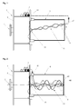
- the in the Fig. 1 for illustration shown device 1 for unwinding and winding one or more lines 2 comprises a rotatable winding body, here in the form of a drum 3.
- the device shown leads the lines from a fixed first connection point 7 in a first partial section from a first position 41 via a second position 42 to a third position 43.
- the helix 44 is provided between the first 41 and the second position 42.
- Position 42 is in Fig. 1 not arranged coaxially with the drum 3, but at a distance A.
- the helix 44 is arranged laterally of the drum 3 and protected by a housing 5.
- the housing 5 is fixed to the rotatable drum 3 in this case.
- the wires 6 of the line 2 are individually guided in the helix.
- device 1 shown for unwinding and winding one or more lines 2 comprises one rotatable bobbin, here in the form of a drum 3.
- the helix 44 is arranged laterally of the drum 3 and protected by a housing 5.
- the housing 5 is fixed to the rotatable drum 3 in this case.
- the wires 6 of the line 2 are individually guided in the helix.
- the helix 44 leads between the first 41 and the second position 42 and between the second 42 and the third position 43 is provided.
- the second position 42 is indicated by a hook or as in Fig. 2 shown as a ring 45 through which the wires 6 are passed or secured.
- the second position 42 is freely rotatably mounted to the housing 5, so that can rotate during unwinding and winding.
- the freely rotatable inflection point within the double helix allows, in principle, a similarly high number of revolutions of the drum as a twice as long individually guided helix, but significantly reduces the dimensions of the housing 5.
- the ring 45 rotates with half Angular velocity of the drum 3.
- the position 42 could also be similar to in Fig. 1 not be arranged coaxially with the drum 3.
Landscapes
- Physics & Mathematics (AREA)
- General Physics & Mathematics (AREA)
- Optics & Photonics (AREA)
- Storing, Repeated Paying-Out, And Re-Storing Of Elongated Articles (AREA)
- Electric Cable Arrangement Between Relatively Moving Parts (AREA)
- Storage Of Web-Like Or Filamentary Materials (AREA)
- Light Guides In General And Applications Therefor (AREA)
Description
Die vorliegende Erfindung betrifft allgemein Vorrichtungen zum Ab- und Aufwickeln einer oder mehreren Leitungen zur unterbrechungsfreien Verbindung zwischen zwei Verbindungspunkten, insbesondere sogenannte Leitungstrommeln, wie Kabeltrommeln, Schlauchtrommeln, usw.The present invention relates generally to devices for unwinding and winding one or more lines for uninterrupted connection between two connection points, in particular so-called line drums, such as cable drums, hose drums, etc.
Vorrichtungen zum Ab- und Aufwickeln einer oder mehreren Leitungen sind allgemein bekannt, haben jedoch je nach Anwendung verschiedene Nachteile.Devices for unwinding and winding one or more lines are well known but have several disadvantages depending on the application.
Sogenannte Kabeltrommeln (eigentlich Leitungsroller) haben z.B. den Nachteil, dass die Stromzufuhr zwar über durchgehende Leitungen erfolgt, zum Ab- oder Aufrollen die Verbindungen zur Trommel jedoch getrennt werden müssen um ein Verdrehen der angeschlossenen Leitungen zu verhindern, da die Steckverbindungen mit der Trommel verbunden sind und so beim Wickelvorgang mitdrehen.So-called cable drums (actually cable reels) have e.g. the disadvantage that the power is indeed through continuous lines, but for unwinding or rolling the connections to the drum must be separated to prevent twisting of the connected lines, since the connectors are connected to the drum and so rotate during the winding process.
Bei sogenannten Automatik-Kabelrollern oder Zugleitungsrollern ist eine Trennung der Steckverbindungen während dem Ab-, bzw. Aufrollvorgang nicht nötig da innerhalb des Rollers die Verbindung über Schleifringe oder -kontakte erfolgt. Dies führt jedoch prinzipbedingt zu einem erhöhten mechanischen Verschleiß und/oder einer gesteigerten Verschmutzungsanfälligkeit. Auch im Fall von fluidführenden Leitungen muss eine Dichtigkeit der Drehkupplungen über längere Benutzungszyklen gewährleistet sein.In so-called automatic cable reels or Zugleitungsrollern a separation of the connectors during the Ab-, or reeling is not necessary because within the scooter, the connection via slip rings or contacts. However, this leads in principle to increased mechanical wear and / or increased susceptibility to soiling. Even in the case of fluid-carrying lines, a tightness of the rotary joints must be ensured over long periods of use.
Außerdem ist die Verwendung von Schleifringen oder Drehkupplungen nicht immer durchführbar. Zum einen verbietet sich die Verwendung von Schleifkontakten in manchen Bereichen z.B. in der Signalübertragung, da Schleifkontakte hier zu erheblichen Beeinträchtigungen führen würden. Zum anderen ist eine solche Lösung auch technisch sehr aufwändig in Fällen wo eine größere Anzahl Leitungen über Schleifringe oder Drehkupplungen oder gemischt mehrere elektrische und fluidführende Leitungen zuverlässig zu überbrücken sind. Außerdem ist in diesem Fall eine kompakte und/oder wirtschaftliche Ausführung der Rolle kaum durchführbar.In addition, the use of slip rings or rotary joints is not always feasible. On the one hand, the use of sliding contacts in some areas, for example, in signal transmission, since sliding contacts here would lead to significant impairment. On the other hand, such a solution is also technically very complicated in cases where a larger number of lines via slip rings or rotary joints or mixed several electrical and fluid lines are to be bridged reliably. In addition, a compact and / or economical design of the role is hardly feasible in this case.
Um die Benutzung von Schleifkontakten zu umgehen sind außerdem Lösungen bekannt in denen eine Leitung durchgehend über zwei Trommeln geführt wird, wobei eine fest steht und eine drehbar angeordnet ist. Beim Abwickeln des nutzbaren Teils der Leitung von der drehbaren Trommel wickelt sich ein anderer Teil der Leitung um die feststehende Trommel auf. Obwohl solche Lösungen kein Abstecken der Verbindungen während dem Wickelvorgang benötigen, bereitet insbesondere das Aufwickeln auf der feststehenden Trommel oft Probleme durch Verwerfungen und Schlaufenbildung der Leitung. Außerdem scheinen solche Vorrichtungen für die Führung mehrerer Leitungen ungeeignet.To circumvent the use of sliding contacts solutions are also known in which a line is continuously passed over two drums, one is fixed and one is rotatably arranged. As the usable portion of the tubing unwinds from the rotatable drum, another portion of the tubing winds around the fixed drum. Although such solutions require no staking of the connections during the winding process, in particular the winding on the fixed drum often causes problems due to warping and looping of the pipe. In addition, such devices seem unsuitable for the guidance of multiple lines.
Schlussendlich wäre es im Hinblick auf die immer umfangreichere Mess-, Kontroll- und Automatisierungstechnik wünschenswert, dass zu den klassischen Anwendungsleitungen zusätzlich (ggf. auch nachträglich) Informations- oder Signalleitungen in einer einzigen Vorrichtung mitgeführt werden könnten.Finally, in view of the increasingly extensive measurement, control and automation technology, it would be desirable for information (or even subsequently) information or signal lines to be included in a single device in addition to the classic application lines.
Eine Aufgabe der vorliegenden Erfindung ist es demnach, eine Vorrichtung zum Ab- und Aufwickeln einer oder mehreren Leitungen zur unterbrechungsfreien Verbindung zwischen zwei Verbindungspunkten zur Verfügung zu stellen die keine Trennung der Leitungen während des Ab- oder Aufwickelvorgangs benötigt und gleichzeitig eine kompakte Ausführung erlaubt.An object of the present invention is therefore to provide a device for unwinding and winding one or more lines for uninterrupted connection between two connection points which does not require separation of the lines during the unwinding or winding operation and at the same time permits a compact design.
Diese Aufgabe wird erfindungsgemäß gelöst durch eine Vorrichtung zum (wenigstens teilweise) Ab- und Aufwickeln einer oder mehreren Leitungen zur unterbrechungsfreien Verbindung jeder der einen oder mehreren Leitungen zwischen zwei Verbindungspunkten, wobei die unterbrechungsfreie Verbindung zwischen einem festen ersten Verbindungspunkt und einem variabel entfernten oder jeweils einem von mehreren unterschiedlich entfernten zweiten Verbindungspunkt herstellbar ist. Die Vorrichtung umfasst einen drehbaren Wickelkörper zum Ab- und Aufwickeln der einen oder mehreren Leitungen. Die Leitung(en) wird/werden vom ersten festen Verbindungspunkt in einem ersten Teilabschnitt von einer feststehenden zum Wickelkörper koaxialen ersten Position zu einer der ersten Position gegenüberliegenden, zweiten Position und von dieser zweiten Position zu einer im wesentlichen in einer Ebene mit der ersten Position aber mit dem Wickelkörper drehbaren dritten Position geführt. Die Leitung(en) im ersten Teilabschnitt wird/werden zwischen der ersten und zweiten Position und zwischen der zweiten und dritten Position freistehend helixförmig geführt, wobei die zweite Position unabhängig vom Wickelkörper frei drehbar angeordnet ist. Die Leitung(en) wird/werden von der dritten Position in einem zweiten Teilabschnitt zur Umfangsseite des Wickelkörpers und ggf. über eine Anzahl Wicklungen um den Wickelkörper zum zweiten Verbindungspunkt geführt.This object is achieved by a device for (at least partially) unwinding and winding one or more lines for uninterrupted connection of each of the one or more lines between two connection points, wherein the uninterrupted connection between a fixed first connection point and a variably removed or one each of several differently distant second connection point can be produced. The device comprises a rotatable winding body for unwinding and winding the one or more lines. The conduit (s) is / are moved from the first fixed connection point in a first subsection from a fixed first position coaxial to the winding body to a second position opposite to the first position and from this second position to substantially in a plane having the first position guided with the winding body rotatable third position. The line (s) in the first section is / are helically guided freestanding between the first and second position and between the second and third position, wherein the second position is arranged freely rotatably independently of the winding body. The line (s) is / are performed by the third position in a second section to the peripheral side of the bobbin and possibly a number of windings around the winding body to the second connection point.
Die erfindungsgemäße Vorrichtung erlaubt es eine oder mehrere Leitungen platzsparend auf- und abzuwickeln je nach Bedarf ohne Entfernen, bzw. Verdrehen der daran befestigten Verbindungsleitungen. Die Länge des helixförmigen Abschnitts zwischen einem feststehendem und einem drehbaren Punkt in Abhängigkeit mit dem minimalen Biegeradius der Leitung(en) bestimmt dabei im Prinzip die mögliche Anzahl der Umdrehungen beim Ab- und Aufwickeln.The device according to the invention allows one or more lines to save space and unwind as needed without removing or twisting the connection lines attached thereto. The length of the helical portion between a fixed and a rotatable point in dependence on the minimum bending radius of the line (s) determines in principle the possible number of revolutions during unwinding and winding.
Das Ab- und Aufwickeln einer oder mehreren Leitungen bedeutet in der Praxis, dass die Leitungen prinzipbedingt nur zu einem (sogenannten nutzbaren) Teil ihrer gesamten Länge ab- und aufwickelbar sind. Dieser nutzbare Teil entspricht im wesentlichen dem im Bereich des Wickelkörpers befindlichen Abschnitts der Leitungen wenn die Leitungen darauf vollständig aufgewickelt sind.The unwinding and winding one or more lines means in practice that the lines are inherently only one (so-called usable) part of their entire length and wound up wound. This usable part essentially corresponds to the portion of the lines located in the region of the winding body when the lines are completely wound on it.
Eine unterbrechungsfreie Verbindung im Sinne der Erfindung bedeutet, dass die Leitungen innerhalb der Vorrichtung nicht durch Verbindungselemente, wie Schleifkontakte, Drehkupplungen oder ähnliches unterbrochen sind, sondern durchgehend vom ersten zum zweiten Verbindungspunkten ausgeführt sind.An uninterrupted connection in the sense of the invention means that the lines within the device are not interrupted by connecting elements, such as sliding contacts, rotary joints or the like, but are executed continuously from the first to the second connection points.
Erfindungsgemäß wird/werden die Leitung(en) zwischen der ersten und zweiten Position (im Raum freistehend) helixförmig geführt. Falls mehrere Leitungen vorhanden sind, können diese zwischen der ersten und zweiten Position seitlich solidarisiert sein oder nicht und so entweder eine oder mehrere Helices bilden.According to the invention, the line (s) between the first and second position (free-standing in space) is / are guided in a helical manner. If multiple lines are present, they may or may not be laterally solidarized between the first and second positions, thus forming either one or more helices.
Erfindungsgemäß wird/werden die Leitung(en) zusätzlich zwischen der zweiten und dritten Position (im Raum freistehend) helixförmig geführt.According to the invention, the line (s) is additionally helically guided between the second and third position (free-standing in space).
Erfindungsgemäß ist die zweite Position unabhängig vom Wickelkörper frei drehbar angeordnet. Diese Ausführung ermöglicht im Prinzip eine Verdopplung der nutzbaren Länge des helixförmigen Abschnitts im Vergleich zu einer Ausführungsform in der die zweite und dritte Position zur ersten Position drehbar aber relativ zueinander fest sind. Der besondere Vorteil ist, dass dies eine platzsparendere Ausführung ohne größeren Aufwand erlaubt und dass darüber hinaus auch unerwünschte Verwerfungen und Schlaufenbildung weitestgehend vermieden werden, was die Zuverlässigkeit und die Betriebssicherheit der Vorrichtung auch über längere Betriebszyklen deutlich erhöht.According to the invention, the second position is freely rotatably arranged independently of the winding body. This embodiment in principle allows a doubling of the usable length of the helical portion as compared to an embodiment in which the second and third positions are rotatable but relative to each other to the first position. The particular advantage is that this allows a space-saving design without much effort and that, moreover, unwanted distortions and looping are largely avoided, which significantly increases the reliability and reliability of the device over longer operating cycles.
In einer bevorzugten Ausführungsform der Vorrichtung ist die zweite Position zur ersten Position axial versetzt angeordnet. Der besondere Vorteil einer exzentrischen Anordnung der zweiten relativ zur ersten Position ist eine bessere Raumausnutzung innerhalb des für die Helix benötigten Raumes. Dabei wird der Abstand (A) zwischen der zweiten Position und einer zur ersten Position koaxialen Position vorzugsweise so gewählt, dass 0,1 d < A < 10 d, bevorzugt 0,2 d < A < 5 d, ganz besonders bevorzugt 0,5 d < A < 2 d beträgt, wobei d der mittlere (effektive) Durchmesser der Helix ist.In a preferred embodiment of the device, the second position is arranged axially offset from the first position. The particular advantage of an eccentric arrangement of the second relative to the first position is a better one Space utilization within the space required for the helix. The distance (A) between the second position and a position coaxial with the first position is preferably selected such that 0.1 d <A <10 d, preferably 0.2 d <A <5 d, very particularly preferably 0.5 d is <A <2 d, where d is the mean (effective) diameter of the helix.
Der mittlere (effektive) Durchmesser des Wickelkörpers (D) bestimmt die Länge der abwickelbaren Leitung pro Umdrehung, während der mittlere (effektive) Durchmesser der Helix (d) größtenteils von dem minimalen Biegeradius der Leitung(en), sowie der gewünschten Anzahl und Durchmesser der Leitungen vorgegeben wird. Der mittlere Durchmesser des Wickelkörpers (D) wird daher in der Praxis bevorzugt relativ groß zum mittleren Durchmesser des Leitungsträgers (d) gewählt, z.B. 1,1 d < D < 100 d oder mehr, bevorzugt 1,5 d < D < 50 d, ganz besonders bevorzugt 2 d < D < 25 d.The mean (effective) diameter of the bobbin (D) determines the length of the unwinding line per revolution, while the average (effective) diameter of the helix (d) largely from the minimum bending radius of the line (s), and the desired number and diameter Lines is specified. The average diameter of the winding body (D) is therefore chosen in practice preferably relatively large to the average diameter of the conductor carrier (d), e.g. 1.1 d <D <100 d or more, preferably 1.5 d <D <50 d, very particularly preferably 2 d <D <25 d.
Die Breite des Leitungsträgers wird bevorzugt so gewählt, dass mindestens die gewünschte Anzahl Leitungen untergebracht werden kann. Ein weiterer Vorteil der Erfindung ist es, dass es sogar möglich ist ohne größeren Aufwand nachträglich weitere Leitungen einzufügen, wenn der Leitungsträger ausreichend dimensioniert ist.The width of the conductor carrier is preferably chosen so that at least the desired number of lines can be accommodated. Another advantage of the invention is that it is even possible without further effort to subsequently insert further lines when the line carrier is sufficiently dimensioned.
In einer bevorzugten Ausführungsform ist der Wickelkörper als hohler Zylinder, bevorzugt als Trommel ausgebildet. Dabei wird der koaxial angeordnete flexible Leitungsträger seitlich versetzt (außerhalb) oder platzsparender innerhalb dieses Zylinders angeordnet.In a preferred embodiment, the winding body is designed as a hollow cylinder, preferably as a drum. In this case, the coaxially arranged flexible conductor carrier is arranged laterally offset (outside) or space-saving within this cylinder.
Leitungen im Sinne der Erfindungen sind energie-, informations-/signal-(z.B. galvanisch oder optisch) oder stoffführende Leitungen, z.B. ein- oder mehradrige Elektrokabel, ein- oder mehradrige optische Kabel (Lichtleiter), ein- oder mehrfach Gas-, Flüssigkeits- oder Feststoff(druck)schläuche, usw. Bei mehradrigen oder mehrfach Leitungen können die Adern oder Kanäle parallel, verdrillt oder koaxial verlaufen. Im Sinne dieser Erfindung kann je nach Kontext der Begriff "Leitung" sowohl die einzelne "Ader" als auch die mehradrige oder mehrkanalige Leitung selbst, z.B. einen Elektrokabel, bezeichnen.Lines within the meaning of the inventions are energy, information / signal (e.g., galvanic or optical) or material carrying lines, e.g. single- or multi-core electrical cables, single or multi-core optical cables (optical fibers), single or multiple gas, liquid or solid (pressure) hoses, etc. In multicore or multiple lines, the wires or channels can be parallel, twisted or coaxial , For the purposes of this invention, depending on the context, the term "conduit" may include both the single "vein" and the multicore or multichannel conduit itself, e.g. an electric cable.
Der Führung mehrerer Leitungen in der Vorrichtung ist somit im Prinzip keine Grenzen gesetzt und die Vorrichtung ist deshalb sehr vielseitig einsetzbar. Mehrere Leitungen können demzufolge (wenigstens abschnittweise) parallel, verdrillt, koaxial oder gemischt parallel, verdrillt und/oder koaxial je nach Art der Leitung oder dessen Anwendung geführt werden. In einer bevorzugten Vorrichtung sind mehrere Leitungen parallel angeordnet.The leadership of multiple lines in the device is therefore in principle no limits and the device is therefore very versatile. Consequently, several lines can be parallel (parallel to one another), twisted, coaxial or mixed, parallel, twisted and / or coaxial, depending on the type of line or its application. In a preferred device several lines are arranged in parallel.
Bevorzugt sind diese Leitungen wenigstens abschnittsweise miteinander verbunden um die Handhabung während des Wickelvorgangs zu erleichtern, z.B. wenigstens im auf- und abwickelbaren Bereich seitlich parallel zueinander, so dass sie im abgewickelten Zustand eine gerade Leitung bilden.Preferably, these lines are at least partially joined together to facilitate handling during the winding operation, e.g. at least in the up and unwindable area laterally parallel to each other, so that they form a straight line in the unwound state.
Im Folgenden wird nun eine Ausgestaltung der Erfindung anhand der beiliegenden Figuren beschrieben. Diese zeigen:
-
Fig. 1 einen Teilquerschnitt einer nicht erfindungsgemäßen Ausführung und -
Fig. 2 einen Teilquerschnitt einer Ausführung der Erfindung.
-
Fig. 1 a partial cross section of a non-inventive embodiment and -
Fig. 2 a partial cross section of an embodiment of the invention.
Weitere Einzelheiten und Vorteile der Erfindung können der nachfolgenden ausführlichen Beschreibung möglicher Ausführungsformen der Erfindung anhand der beiliegenden Figuren entnommen werden.Further details and advantages of the invention can be taken from the following detailed description of possible embodiments of the invention with reference to the accompanying figures.
Die in der
Die in der
In der in
- 11
- Vorrichtung zum Ab- und Aufwickeln einer oder mehreren LeitungenDevice for unwinding and winding one or more lines
- 22
- Leitungen (auf der Trommel)Pipes (on the drum)
- 33
- Trommeldrum
- 4141
- erste Positionfirst position
- 4242
- zweite Positionsecond position
- 4343
- dritte Positionthird position
- 4444
- Helixhelix
- 4545
- Ringring
- 55
- Gehäusecasing
- 66
- Leitungen (bevorzugt als einzelne Adern im Bereich der Helix)Lines (preferably as individual wires in the area of the helix)
- 77
- erster Verbindungspunktfirst connection point
Claims (11)
- A device (1) for unwinding and winding up one or more lines (2) for uninterrupted connection of each of the one or more lines between two connection points, wherein the uninterrupted connection may be produced between a fixed first connection point (7) and a second connection point which is at a variable distance or in each case one of a plurality of second connection points which are at different distances, wherein the device comprises a rotatable winding body (3) for unwinding and winding up the one or more lines, wherein the line(s) is/are guided in a first sub-portion from the first fixed connection point from a stationary first position (41) coaxial with the winding body to a second position (42) located opposite the first position and from said second position to a third position (43) substantially in a plane with the first position but rotatable with the winding body, wherein the line(s) is/are guided helically in the first sub-portion between the first and second positions, wherein the line(s) is/are guided from the third position in a second sub-portion to the circumferential side of the winding body and optionally via a number of windings around the winding body to the second connection point, characterised in that the line(s) is/are guided helically in the first sub-portion between the second and third positions and in that the second position is arranged freely rotatably independently of the winding body.
- A device according to claim 1, wherein the second position is arranged at an axial offset to the first position.
- A device according to one of claims 1 to 2, wherein the distance A between the second position and a position coaxial with the first position is selected such that 0.1 d < A < 10 d, preferably 0.2 d < A < 5 d, particularly preferably 0.5 d < A < 2 d, wherein d is the average (effective) diameter of the helix.
- A device according to one of claims 1 to 3, wherein the winding body takes the form of a hollow cylinder, preferably a drum.
- A device according to claim 4, wherein the first sub-portion of the line(s) is arranged laterally of said hollow cylinder or said drum.
- A device according to claim 4, wherein the first sub-portion of the line(s) is arranged within said hollow cylinder or said drum.
- A device according to one of claims 1 to 6, wherein a plurality of electrical and/or fluid-conveying lines are connected together at least in portions in a parallel, twisted or coaxial manner or in a mixture of parallel, twisted and/or coaxial manners.
- A device according to one of claims 1 to 6, wherein a plurality of electrical and/or fluid-conveying lines are arranged in parallel.
- A device according to claim 8, wherein the plurality of lines are laterally connected at least in portions.
- A device according to one of claims 1 to 9, wherein the average diameter d of the helix of the line(s) is smaller than the average diameter D of the winding body, preferably 1.1 d < D < 100 d, particularly preferably 1.5 d < D < 50 d and in particular 2 d < D < 25 d.
- A device according to one of claims 1 to 10, wherein the lines are power-, data-/signal- or material-conveying lines, for example single- or multi-core electrical cables, single- or multi-core galvanic or optical conductors or single or multiple gas, liquid or solids (pressure) hoses.
Applications Claiming Priority (2)
| Application Number | Priority Date | Filing Date | Title |
|---|---|---|---|
| LU91826A LU91826B1 (en) | 2011-06-17 | 2011-06-17 | Device for unwinding and winding up one or more lines |
| PCT/EP2012/061604 WO2012172110A1 (en) | 2011-06-17 | 2012-06-18 | Device for unwinding and winding up one or more lines |
Publications (2)
| Publication Number | Publication Date |
|---|---|
| EP2720970A1 EP2720970A1 (en) | 2014-04-23 |
| EP2720970B1 true EP2720970B1 (en) | 2016-10-05 |
Family
ID=46458456
Family Applications (1)
| Application Number | Title | Priority Date | Filing Date |
|---|---|---|---|
| EP12732574.4A Active EP2720970B1 (en) | 2011-06-17 | 2012-06-18 | Device for unwinding and winding up one or more lines |
Country Status (8)
| Country | Link |
|---|---|
| US (1) | US9620948B2 (en) |
| EP (1) | EP2720970B1 (en) |
| JP (1) | JP6008955B2 (en) |
| CN (1) | CN103648944B (en) |
| CA (1) | CA2838548C (en) |
| ES (1) | ES2609605T3 (en) |
| LU (1) | LU91826B1 (en) |
| WO (1) | WO2012172110A1 (en) |
Families Citing this family (4)
| Publication number | Priority date | Publication date | Assignee | Title |
|---|---|---|---|---|
| CN104914534B (en) * | 2015-05-29 | 2017-12-08 | 成都亨通光通信有限公司 | A kind of application method of optical cable admission machine |
| CN107631137B (en) * | 2017-09-28 | 2024-02-09 | 天津汇讯视通科技有限公司 | Tripod head camera winding structure |
| JP7081311B2 (en) * | 2018-06-04 | 2022-06-07 | 京セラドキュメントソリューションズ株式会社 | Image forming device |
| CN111252631B (en) * | 2020-03-24 | 2024-08-09 | 士商(湖州)精密技术有限公司 | Intelligent electric winder and control method thereof |
Family Cites Families (21)
| Publication number | Priority date | Publication date | Assignee | Title |
|---|---|---|---|---|
| US2141909A (en) * | 1938-05-21 | 1938-12-27 | Edward J Hauser | Floor lamp with cord take-up device |
| NL68475C (en) * | 1946-05-02 | |||
| DE830371C (en) * | 1950-02-21 | 1952-02-04 | Paul Meyer | Winding device for the pendulum cord of height-adjustable electric hanging lights |
| GB691817A (en) * | 1951-02-01 | 1953-05-20 | Clyde Crane & Booth Ltd | Improvements in devices for winding up electric conductors |
| US3144218A (en) * | 1961-06-26 | 1964-08-11 | Gen Dynamics Corp | Transmission cable storing and positioning mechanism |
| US3372887A (en) * | 1966-03-23 | 1968-03-12 | Ladany Shaul | Retractable cord device |
| GB1217332A (en) * | 1967-03-17 | 1970-12-31 | Plessey Co Ltd | Improvements in or relating to reeling apparatus |
| SE7809764L (en) * | 1978-09-15 | 1980-03-16 | Hansson Nils Ove | CABLE TRANSMISSION |
| JPS57115522A (en) | 1981-01-09 | 1982-07-19 | Alps Electric Co Ltd | Liquid crystal display |
| JPS6211148Y2 (en) * | 1981-01-09 | 1987-03-16 | ||
| JPS5874466A (en) * | 1981-10-26 | 1983-05-04 | Sumitomo Heavy Ind Ltd | Cable coupling device of rotary part to stationary part in cable winder |
| DE8522019U1 (en) * | 1985-07-31 | 1985-11-14 | Manfred Fladung GmbH, 8752 Mömbris | Device for stowing the connection cable of a central on-board power supply system |
| JPS6443469A (en) * | 1987-08-11 | 1989-02-15 | Hitachi Ltd | Cable container |
| DE9010213U1 (en) * | 1990-07-05 | 1990-10-18 | Manfred Fladung GmbH, 63776 Mömbris | Device for storing a thick cable |
| JPH06276655A (en) | 1993-03-16 | 1994-09-30 | Kubota Corp | Electric wiring construction relative rotating body |
| SE505396C2 (en) * | 1995-11-09 | 1997-08-18 | Electrolux Ab | Towing device for a cable reel with a cable drum rotating on a stationary shaft |
| DE19621490C1 (en) * | 1996-05-29 | 1997-09-18 | Schaeff Karl Gmbh & Co | Supply cable drum for electric crane or mining machine |
| JP3178354B2 (en) | 1996-05-31 | 2001-06-18 | 株式会社日立製作所 | Washing machine |
| JP4281034B2 (en) * | 1999-12-24 | 2009-06-17 | 城勝 浦 | Cleaning hose storage device |
| JP5037191B2 (en) | 2007-03-27 | 2012-09-26 | 東京エレクトロン株式会社 | Substrate transfer device and cable wiring structure |
| JP4206426B1 (en) * | 2008-05-30 | 2009-01-14 | モリテックスチール株式会社 | Long body take-up reel device |
-
2011
- 2011-06-17 LU LU91826A patent/LU91826B1/en active
-
2012
- 2012-06-18 US US14/126,647 patent/US9620948B2/en active Active
- 2012-06-18 WO PCT/EP2012/061604 patent/WO2012172110A1/en active Application Filing
- 2012-06-18 JP JP2014515228A patent/JP6008955B2/en active Active
- 2012-06-18 ES ES12732574.4T patent/ES2609605T3/en active Active
- 2012-06-18 CA CA2838548A patent/CA2838548C/en active Active
- 2012-06-18 CN CN201280029743.0A patent/CN103648944B/en active Active
- 2012-06-18 EP EP12732574.4A patent/EP2720970B1/en active Active
Also Published As
| Publication number | Publication date |
|---|---|
| LU91826B1 (en) | 2012-12-18 |
| JP2014519805A (en) | 2014-08-14 |
| JP6008955B2 (en) | 2016-10-19 |
| CN103648944A (en) | 2014-03-19 |
| WO2012172110A1 (en) | 2012-12-20 |
| CA2838548C (en) | 2019-01-08 |
| ES2609605T3 (en) | 2017-04-21 |
| US9620948B2 (en) | 2017-04-11 |
| CA2838548A1 (en) | 2012-12-20 |
| CN103648944B (en) | 2016-05-25 |
| US20140217225A1 (en) | 2014-08-07 |
| NZ618550A (en) | 2015-07-31 |
| EP2720970A1 (en) | 2014-04-23 |
Similar Documents
| Publication | Publication Date | Title |
|---|---|---|
| DE69318291T3 (en) | METHOD AND DEVICE FOR PRODUCING A CONNECTING CABLE | |
| EP3445695B1 (en) | Routing system for at least one supply line which can be coiled and uncoiled, and rotary guide therefor | |
| DE69215591T2 (en) | Connector system with fiber optic cable with a metal tube jacket | |
| DE102016204832B3 (en) | Guide device and X-ray device | |
| EP2720970B1 (en) | Device for unwinding and winding up one or more lines | |
| EP3111524B1 (en) | Laying aid for a cable, in particular an induction cable | |
| EP3626662A1 (en) | Cable reel | |
| WO2018192955A1 (en) | Magazine apparatus for lines and line-guiding devices | |
| DE1665421A1 (en) | Reel device | |
| EP2535303A1 (en) | Apparatus for unwinding and winding one or more conductors | |
| DE4426395C2 (en) | Charger with a power cord and a consumer connection | |
| DE3133842C2 (en) | Device for operational winding and unwinding of electrical cables | |
| EP2875987A1 (en) | Electrical wire and electrical machine | |
| EP4031790B1 (en) | Rotary guide for one or more lines | |
| EP4077184B1 (en) | Energy supply system | |
| DE10017599A1 (en) | Towing cable winch, for decoy bodies towed by combat aircraft, has multi-stage planetary gear with secondary stage driving hollow cylinder with curved groove engaged by drive pin for moving drum when cylinder turns | |
| EP3499518B1 (en) | Electric conductor made of solid segments | |
| DE202018101827U1 (en) | Modular rotary feedthrough with energy guiding chains | |
| EP3423880B1 (en) | Submarine communications cable, and method and device for the production thereof | |
| EP1859521B1 (en) | Tube | |
| DE102019131782A1 (en) | Motor-line reel arrangement or motor-hose-reel arrangement | |
| EP2548831A2 (en) | Conduit reservoir for holding an electrical, optical or fluid conduit | |
| DE4004401C2 (en) | Winding device for a line arrangement | |
| DE9210074U1 (en) | Drag chain replacement with spring | |
| EP4402084A1 (en) | Reel arrangement |
Legal Events
| Date | Code | Title | Description |
|---|---|---|---|
| PUAI | Public reference made under article 153(3) epc to a published international application that has entered the european phase |
Free format text: ORIGINAL CODE: 0009012 |
|
| 17P | Request for examination filed |
Effective date: 20131203 |
|
| AK | Designated contracting states |
Kind code of ref document: A1 Designated state(s): AL AT BE BG CH CY CZ DE DK EE ES FI FR GB GR HR HU IE IS IT LI LT LU LV MC MK MT NL NO PL PT RO RS SE SI SK SM TR |
|
| DAX | Request for extension of the european patent (deleted) | ||
| 17Q | First examination report despatched |
Effective date: 20151016 |
|
| GRAP | Despatch of communication of intention to grant a patent |
Free format text: ORIGINAL CODE: EPIDOSNIGR1 |
|
| INTG | Intention to grant announced |
Effective date: 20160502 |
|
| GRAS | Grant fee paid |
Free format text: ORIGINAL CODE: EPIDOSNIGR3 |
|
| GRAA | (expected) grant |
Free format text: ORIGINAL CODE: 0009210 |
|
| AK | Designated contracting states |
Kind code of ref document: B1 Designated state(s): AL AT BE BG CH CY CZ DE DK EE ES FI FR GB GR HR HU IE IS IT LI LT LU LV MC MK MT NL NO PL PT RO RS SE SI SK SM TR |
|
| REG | Reference to a national code |
Ref country code: GB Ref legal event code: FG4D Free format text: NOT ENGLISH |
|
| REG | Reference to a national code |
Ref country code: CH Ref legal event code: EP |
|
| REG | Reference to a national code |
Ref country code: AT Ref legal event code: REF Ref document number: 834447 Country of ref document: AT Kind code of ref document: T Effective date: 20161015 |
|
| REG | Reference to a national code |
Ref country code: IE Ref legal event code: FG4D Free format text: LANGUAGE OF EP DOCUMENT: GERMAN |
|
| REG | Reference to a national code |
Ref country code: DE Ref legal event code: R096 Ref document number: 502012008434 Country of ref document: DE |
|
| REG | Reference to a national code |
Ref country code: NL Ref legal event code: MP Effective date: 20161005 |
|
| REG | Reference to a national code |
Ref country code: LT Ref legal event code: MG4D |
|
| PG25 | Lapsed in a contracting state [announced via postgrant information from national office to epo] |
Ref country code: LV Free format text: LAPSE BECAUSE OF FAILURE TO SUBMIT A TRANSLATION OF THE DESCRIPTION OR TO PAY THE FEE WITHIN THE PRESCRIBED TIME-LIMIT Effective date: 20161005 |
|
| REG | Reference to a national code |
Ref country code: ES Ref legal event code: FG2A Ref document number: 2609605 Country of ref document: ES Kind code of ref document: T3 Effective date: 20170421 |
|
| PG25 | Lapsed in a contracting state [announced via postgrant information from national office to epo] |
Ref country code: GR Free format text: LAPSE BECAUSE OF FAILURE TO SUBMIT A TRANSLATION OF THE DESCRIPTION OR TO PAY THE FEE WITHIN THE PRESCRIBED TIME-LIMIT Effective date: 20170106 Ref country code: SE Free format text: LAPSE BECAUSE OF FAILURE TO SUBMIT A TRANSLATION OF THE DESCRIPTION OR TO PAY THE FEE WITHIN THE PRESCRIBED TIME-LIMIT Effective date: 20161005 Ref country code: LT Free format text: LAPSE BECAUSE OF FAILURE TO SUBMIT A TRANSLATION OF THE DESCRIPTION OR TO PAY THE FEE WITHIN THE PRESCRIBED TIME-LIMIT Effective date: 20161005 Ref country code: NO Free format text: LAPSE BECAUSE OF FAILURE TO SUBMIT A TRANSLATION OF THE DESCRIPTION OR TO PAY THE FEE WITHIN THE PRESCRIBED TIME-LIMIT Effective date: 20170105 |
|
| REG | Reference to a national code |
Ref country code: FR Ref legal event code: PLFP Year of fee payment: 6 |
|
| PG25 | Lapsed in a contracting state [announced via postgrant information from national office to epo] |
Ref country code: RS Free format text: LAPSE BECAUSE OF FAILURE TO SUBMIT A TRANSLATION OF THE DESCRIPTION OR TO PAY THE FEE WITHIN THE PRESCRIBED TIME-LIMIT Effective date: 20161005 Ref country code: FI Free format text: LAPSE BECAUSE OF FAILURE TO SUBMIT A TRANSLATION OF THE DESCRIPTION OR TO PAY THE FEE WITHIN THE PRESCRIBED TIME-LIMIT Effective date: 20161005 Ref country code: PT Free format text: LAPSE BECAUSE OF FAILURE TO SUBMIT A TRANSLATION OF THE DESCRIPTION OR TO PAY THE FEE WITHIN THE PRESCRIBED TIME-LIMIT Effective date: 20170206 Ref country code: PL Free format text: LAPSE BECAUSE OF FAILURE TO SUBMIT A TRANSLATION OF THE DESCRIPTION OR TO PAY THE FEE WITHIN THE PRESCRIBED TIME-LIMIT Effective date: 20161005 Ref country code: IS Free format text: LAPSE BECAUSE OF FAILURE TO SUBMIT A TRANSLATION OF THE DESCRIPTION OR TO PAY THE FEE WITHIN THE PRESCRIBED TIME-LIMIT Effective date: 20170205 Ref country code: NL Free format text: LAPSE BECAUSE OF FAILURE TO SUBMIT A TRANSLATION OF THE DESCRIPTION OR TO PAY THE FEE WITHIN THE PRESCRIBED TIME-LIMIT Effective date: 20161005 Ref country code: HR Free format text: LAPSE BECAUSE OF FAILURE TO SUBMIT A TRANSLATION OF THE DESCRIPTION OR TO PAY THE FEE WITHIN THE PRESCRIBED TIME-LIMIT Effective date: 20161005 |
|
| REG | Reference to a national code |
Ref country code: DE Ref legal event code: R097 Ref document number: 502012008434 Country of ref document: DE |
|
| PG25 | Lapsed in a contracting state [announced via postgrant information from national office to epo] |
Ref country code: DK Free format text: LAPSE BECAUSE OF FAILURE TO SUBMIT A TRANSLATION OF THE DESCRIPTION OR TO PAY THE FEE WITHIN THE PRESCRIBED TIME-LIMIT Effective date: 20161005 Ref country code: SK Free format text: LAPSE BECAUSE OF FAILURE TO SUBMIT A TRANSLATION OF THE DESCRIPTION OR TO PAY THE FEE WITHIN THE PRESCRIBED TIME-LIMIT Effective date: 20161005 Ref country code: CZ Free format text: LAPSE BECAUSE OF FAILURE TO SUBMIT A TRANSLATION OF THE DESCRIPTION OR TO PAY THE FEE WITHIN THE PRESCRIBED TIME-LIMIT Effective date: 20161005 Ref country code: EE Free format text: LAPSE BECAUSE OF FAILURE TO SUBMIT A TRANSLATION OF THE DESCRIPTION OR TO PAY THE FEE WITHIN THE PRESCRIBED TIME-LIMIT Effective date: 20161005 Ref country code: RO Free format text: LAPSE BECAUSE OF FAILURE TO SUBMIT A TRANSLATION OF THE DESCRIPTION OR TO PAY THE FEE WITHIN THE PRESCRIBED TIME-LIMIT Effective date: 20161005 |
|
| PLBE | No opposition filed within time limit |
Free format text: ORIGINAL CODE: 0009261 |
|
| STAA | Information on the status of an ep patent application or granted ep patent |
Free format text: STATUS: NO OPPOSITION FILED WITHIN TIME LIMIT |
|
| PG25 | Lapsed in a contracting state [announced via postgrant information from national office to epo] |
Ref country code: BG Free format text: LAPSE BECAUSE OF FAILURE TO SUBMIT A TRANSLATION OF THE DESCRIPTION OR TO PAY THE FEE WITHIN THE PRESCRIBED TIME-LIMIT Effective date: 20170105 Ref country code: SM Free format text: LAPSE BECAUSE OF FAILURE TO SUBMIT A TRANSLATION OF THE DESCRIPTION OR TO PAY THE FEE WITHIN THE PRESCRIBED TIME-LIMIT Effective date: 20161005 |
|
| 26N | No opposition filed |
Effective date: 20170706 |
|
| PG25 | Lapsed in a contracting state [announced via postgrant information from national office to epo] |
Ref country code: SI Free format text: LAPSE BECAUSE OF FAILURE TO SUBMIT A TRANSLATION OF THE DESCRIPTION OR TO PAY THE FEE WITHIN THE PRESCRIBED TIME-LIMIT Effective date: 20161005 |
|
| PG25 | Lapsed in a contracting state [announced via postgrant information from national office to epo] |
Ref country code: MC Free format text: LAPSE BECAUSE OF FAILURE TO SUBMIT A TRANSLATION OF THE DESCRIPTION OR TO PAY THE FEE WITHIN THE PRESCRIBED TIME-LIMIT Effective date: 20161005 |
|
| REG | Reference to a national code |
Ref country code: CH Ref legal event code: PL |
|
| REG | Reference to a national code |
Ref country code: IE Ref legal event code: MM4A |
|
| REG | Reference to a national code |
Ref country code: FR Ref legal event code: PLFP Year of fee payment: 7 |
|
| PG25 | Lapsed in a contracting state [announced via postgrant information from national office to epo] |
Ref country code: CH Free format text: LAPSE BECAUSE OF NON-PAYMENT OF DUE FEES Effective date: 20170630 Ref country code: LI Free format text: LAPSE BECAUSE OF NON-PAYMENT OF DUE FEES Effective date: 20170630 Ref country code: IE Free format text: LAPSE BECAUSE OF NON-PAYMENT OF DUE FEES Effective date: 20170618 Ref country code: LU Free format text: LAPSE BECAUSE OF NON-PAYMENT OF DUE FEES Effective date: 20170618 |
|
| REG | Reference to a national code |
Ref country code: BE Ref legal event code: MM Effective date: 20170630 |
|
| REG | Reference to a national code |
Ref country code: AT Ref legal event code: MM01 Ref document number: 834447 Country of ref document: AT Kind code of ref document: T Effective date: 20170618 |
|
| PG25 | Lapsed in a contracting state [announced via postgrant information from national office to epo] |
Ref country code: BE Free format text: LAPSE BECAUSE OF NON-PAYMENT OF DUE FEES Effective date: 20170630 |
|
| PG25 | Lapsed in a contracting state [announced via postgrant information from national office to epo] |
Ref country code: MT Free format text: LAPSE BECAUSE OF FAILURE TO SUBMIT A TRANSLATION OF THE DESCRIPTION OR TO PAY THE FEE WITHIN THE PRESCRIBED TIME-LIMIT Effective date: 20161005 |
|
| PG25 | Lapsed in a contracting state [announced via postgrant information from national office to epo] |
Ref country code: AT Free format text: LAPSE BECAUSE OF NON-PAYMENT OF DUE FEES Effective date: 20170618 |
|
| PG25 | Lapsed in a contracting state [announced via postgrant information from national office to epo] |
Ref country code: HU Free format text: LAPSE BECAUSE OF FAILURE TO SUBMIT A TRANSLATION OF THE DESCRIPTION OR TO PAY THE FEE WITHIN THE PRESCRIBED TIME-LIMIT; INVALID AB INITIO Effective date: 20120618 |
|
| PG25 | Lapsed in a contracting state [announced via postgrant information from national office to epo] |
Ref country code: CY Free format text: LAPSE BECAUSE OF NON-PAYMENT OF DUE FEES Effective date: 20161005 |
|
| PG25 | Lapsed in a contracting state [announced via postgrant information from national office to epo] |
Ref country code: MK Free format text: LAPSE BECAUSE OF FAILURE TO SUBMIT A TRANSLATION OF THE DESCRIPTION OR TO PAY THE FEE WITHIN THE PRESCRIBED TIME-LIMIT Effective date: 20161005 |
|
| PG25 | Lapsed in a contracting state [announced via postgrant information from national office to epo] |
Ref country code: TR Free format text: LAPSE BECAUSE OF FAILURE TO SUBMIT A TRANSLATION OF THE DESCRIPTION OR TO PAY THE FEE WITHIN THE PRESCRIBED TIME-LIMIT Effective date: 20161005 |
|
| PG25 | Lapsed in a contracting state [announced via postgrant information from national office to epo] |
Ref country code: AL Free format text: LAPSE BECAUSE OF FAILURE TO SUBMIT A TRANSLATION OF THE DESCRIPTION OR TO PAY THE FEE WITHIN THE PRESCRIBED TIME-LIMIT Effective date: 20161005 |
|
| REG | Reference to a national code |
Ref country code: DE Ref legal event code: R082 Ref document number: 502012008434 Country of ref document: DE |
|
| PGFP | Annual fee paid to national office [announced via postgrant information from national office to epo] |
Ref country code: IT Payment date: 20230412 Year of fee payment: 12 |
|
| PGFP | Annual fee paid to national office [announced via postgrant information from national office to epo] |
Ref country code: ES Payment date: 20230728 Year of fee payment: 12 |
|
| PGFP | Annual fee paid to national office [announced via postgrant information from national office to epo] |
Ref country code: GB Payment date: 20240416 Year of fee payment: 13 |
|
| PGFP | Annual fee paid to national office [announced via postgrant information from national office to epo] |
Ref country code: DE Payment date: 20240524 Year of fee payment: 13 |
|
| PGFP | Annual fee paid to national office [announced via postgrant information from national office to epo] |
Ref country code: FR Payment date: 20240419 Year of fee payment: 13 |