EP2720945B1 - Elektrische antriebsvorrichtung für ein luftfahrzeug - Google Patents
Elektrische antriebsvorrichtung für ein luftfahrzeug Download PDFInfo
- Publication number
- EP2720945B1 EP2720945B1 EP12740465.5A EP12740465A EP2720945B1 EP 2720945 B1 EP2720945 B1 EP 2720945B1 EP 12740465 A EP12740465 A EP 12740465A EP 2720945 B1 EP2720945 B1 EP 2720945B1
- Authority
- EP
- European Patent Office
- Prior art keywords
- drive device
- aircraft
- lithium
- coolant
- battery
- Prior art date
- Legal status (The legal status is an assumption and is not a legal conclusion. Google has not performed a legal analysis and makes no representation as to the accuracy of the status listed.)
- Active
Links
Images

Classifications
-
- B—PERFORMING OPERATIONS; TRANSPORTING
- B64—AIRCRAFT; AVIATION; COSMONAUTICS
- B64D—EQUIPMENT FOR FITTING IN OR TO AIRCRAFT; FLIGHT SUITS; PARACHUTES; ARRANGEMENT OR MOUNTING OF POWER PLANTS OR PROPULSION TRANSMISSIONS IN AIRCRAFT
- B64D33/00—Arrangement in aircraft of power plant parts or auxiliaries not otherwise provided for
- B64D33/08—Arrangement in aircraft of power plant parts or auxiliaries not otherwise provided for of power plant cooling systems
-
- B—PERFORMING OPERATIONS; TRANSPORTING
- B64—AIRCRAFT; AVIATION; COSMONAUTICS
- B64D—EQUIPMENT FOR FITTING IN OR TO AIRCRAFT; FLIGHT SUITS; PARACHUTES; ARRANGEMENT OR MOUNTING OF POWER PLANTS OR PROPULSION TRANSMISSIONS IN AIRCRAFT
- B64D27/00—Arrangement or mounting of power plants in aircraft; Aircraft characterised by the type or position of power plants
- B64D27/02—Aircraft characterised by the type or position of power plants
- B64D27/30—Aircraft characterised by electric power plants
- B64D27/34—All-electric aircraft
-
- B—PERFORMING OPERATIONS; TRANSPORTING
- B64—AIRCRAFT; AVIATION; COSMONAUTICS
- B64D—EQUIPMENT FOR FITTING IN OR TO AIRCRAFT; FLIGHT SUITS; PARACHUTES; ARRANGEMENT OR MOUNTING OF POWER PLANTS OR PROPULSION TRANSMISSIONS IN AIRCRAFT
- B64D27/00—Arrangement or mounting of power plants in aircraft; Aircraft characterised by the type or position of power plants
- B64D27/02—Aircraft characterised by the type or position of power plants
- B64D27/30—Aircraft characterised by electric power plants
- B64D27/35—Arrangements for on-board electric energy production, distribution, recovery or storage
- B64D27/357—Arrangements for on-board electric energy production, distribution, recovery or storage using batteries
-
- B—PERFORMING OPERATIONS; TRANSPORTING
- B64—AIRCRAFT; AVIATION; COSMONAUTICS
- B64D—EQUIPMENT FOR FITTING IN OR TO AIRCRAFT; FLIGHT SUITS; PARACHUTES; ARRANGEMENT OR MOUNTING OF POWER PLANTS OR PROPULSION TRANSMISSIONS IN AIRCRAFT
- B64D31/00—Power plant control systems; Arrangement of power plant control systems in aircraft
- B64D31/16—Power plant control systems; Arrangement of power plant control systems in aircraft for electric power plants
-
- Y—GENERAL TAGGING OF NEW TECHNOLOGICAL DEVELOPMENTS; GENERAL TAGGING OF CROSS-SECTIONAL TECHNOLOGIES SPANNING OVER SEVERAL SECTIONS OF THE IPC; TECHNICAL SUBJECTS COVERED BY FORMER USPC CROSS-REFERENCE ART COLLECTIONS [XRACs] AND DIGESTS
- Y02—TECHNOLOGIES OR APPLICATIONS FOR MITIGATION OR ADAPTATION AGAINST CLIMATE CHANGE
- Y02T—CLIMATE CHANGE MITIGATION TECHNOLOGIES RELATED TO TRANSPORTATION
- Y02T50/00—Aeronautics or air transport
- Y02T50/60—Efficient propulsion technologies, e.g. for aircraft
Definitions
- the invention relates to an electric drive device for an aircraft, comprising at least one battery for storing electrical energy, an electric motor for driving a propeller, a conduit means for transmitting the electrical energy from the battery to the electric motor, and a first control means for controlling the electric motor.
- the invention finds application in the aircraft industry.
- the object of the invention is to provide an improved electric drive device which is suitable for driving larger aircraft for passenger or freight transport.
- an aircraft propulsion device comprising at least one battery for storing electrical energy, an electric motor for driving a propeller, a conduit for transmitting the electrical energy from the battery to the electric motor, and a first control means for controlling the electric motor
- the drive device according to the invention is also characterized in that the battery is a lithium-air battery; the electric motor is a high temperature superconductor motor; there is at least one reservoir for a coolant and a cooling system connected to the reservoir for cooling the high temperature superconductor motor, the cooling system comprising a second control means for controlling the cooling system; a first means for variable arrangement of the lithium-air battery and / or a second means for variable arrangement of the memory in the aircraft is / are; and a third control means for controlling the first and / or the second means is provided, wherein the control of the first and / or the second means takes place such that the lithium-air battery and / or the memory in the aircraft are arranged such that a mass increase of the lithium-air battery resulting during operation of the drive
- the lithium-air battery and its operating principle are known in the art.
- the lithium-air battery is characterized by a particularly high energy density of theoretically up to more than 5,000 Wh / kg with an open circuit voltage of 2.91 V.
- the lithium Li of the anode is oxidized to lithium oxide Li 2 O or lithium peroxide Li 2 O 2 .
- the drive device comprises a reservoir with coolant, with which at least the high-temperature superconductor motor, and preferably also the conduit means as far as can be cooled, that superconductivity occurs.
- the coolant in the reservoir is preferably liquid nitrogen. Possible alternatives are liquid hydrogen or liquid helium.
- the conductive agent is preferably a copper oxide-based high-temperature superconductor. For cooling the high-temperature superconductor motor or the conduit means, the coolant is brought into thermally conductive contact with the high-temperature superconductor motor or the conduit means.
- the coolant in the present case ultimately discharged into the free atmosphere, so that the coolant level in the memory decreases during operation.
- the release of nitrogen to the atmosphere is harmless for environmental reasons.
- the loss of coolant in the reservoir leads to a mass or weight loss of the coolant contained in the memory.
- the lithium-air battery and / or the memory with the coolant in the aircraft can be variably arranged.
- the lithium-air battery and / or the memory are arranged in the fuselage of the aircraft.
- the lithium-air battery is arranged in a housing having the outer dimensions of a standard air cargo container, in particular LD3, LD6.
- a standard air cargo container in particular LD3, LD6.
- the first means is present. It comprises a drive (eg a linear drive) and a corresponding mechanism.
- the second means is analogously available.
- the arrangement of the lithium-air battery and / or the memory of the third control means is controlled such that a center of gravity of the aircraft does not change.
- only the lithium-air battery can be variably arranged in the aircraft.
- a preferred embodiment of the drive device according to the invention is characterized in that the lithium-air battery has a pressure-tight housing, which is supplied with external air via a separate, in particular one of an air supply to a passenger cabin of the aircraft independent air supply.
- This independent air supply can allow for a flying height dependent printing of the pressure-tight battery housing. By separating the air supply, the air supply can be optimally adapted to the needs of the lithium-air battery.
- a further preferred development of the drive device according to the invention is characterized in that in addition to the high-temperature superconductor motor and the conduit means is superconducting, and that the cooling system is designed and set up for cooling the conduit means.
- the electrical energy can be transferred almost loss-free from the lithium-air battery to the high-temperature superconductor electric motor.
- the cooling system is designed and set up such that the coolant is supplied from the store in normal operation to the following components in the following order, first the conduit, then the electric motor and subsequently other systems of the aircraft, in particular the first control means second control means, the third control means and / or avionics systems, before the coolant flows out through an outlet in an environment.
- a further preferred embodiment of the drive device according to the invention is characterized in that the second control means and the cooling system are designed and arranged such that a ranking can be determined depending on a drive power retrieved by the drive device according to the invention, with which a cooling of the individual components is to take place. and the coolant is supplied to the individual components according to the ranking.
- the cooling predominantly of the high temperature superconductor motor and second priority of the conduit means, while the cooling of the other system components only in a reduced form and not he follows.
- a particularly preferred development of the drive device according to the invention is characterized in that solar cells, at least one fuel cell and / or an internal combustion engine with an electric generator are present for charging the battery and / or for providing further electrical energy.
- the drive device may in particular comprise two electric motors, each driving a propeller whose propeller axes are mounted concentrically.
- the invention further comprises an aircraft with a drive device as described above.
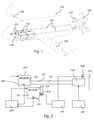
- Fig. 1 shows a schematic representation of an integrated into an aircraft 100 with conventional lifting surfaces 106 (wings) inventive drive device.
- the aircraft 100 is designed to carry a payload of 6,600 kg (about 70 passengers) over a distance of 500 nautical miles [NM] at an airspeed of 500 km / h.
- a lift-to-drag-ratio of 24 applies for the aircraft 100.
- To start the aircraft 100 approximately 4,000 kW are needed at short notice.
- a lithium-air battery 101 with a mass of 4,570 kg with a battery volume of approximately 6.8 m 3 is provided.
- the lithium-air battery 101 has an energy density of 1,000 Wh / kg.
- the lithium-air battery 101 consists in the present case of two interconnected lithium-air batteries 101, each housed in a standard air freight container LD3.
- the containers are slidably disposed along the longitudinal axis of the aircraft 100 (indicated by the arrow above the batteries 101).
- the aircraft 100 further comprises an electric motor 103 for driving a double propeller 104 at the rear of the aircraft 100, and a superconductive conduit means 102 for transmitting electrical energy from the lithium-air batteries 101 to the electric motor 103.
- the conduit means 102 is surrounded by coolant lines 107, the cool the conduit to maintain superconductivity.
- the coolant is stored in a memory 105 also displaceably arranged along the longitudinal axis of the aircraft.
- the electric motor 103 is configured here as a high-temperature superconductor motor and is also cooled by the coolant.
- Fig. 2 shows a schematic representation for explaining the interaction of components of the drive device according to the invention for in Fig. 1
- the aircraft includes a battery 101 for storing electrical energy, a high-temperature superconductor motor 103 for driving a propeller 104, a conduit 102 for transferring the electrical energy from the battery 101 to the high-temperature superconductor motor 103, and a first control means 201 for controlling the electric motor 103.
- the drive apparatus is further characterized in that the battery 101 is a lithium-air battery; the conduit 102 is superconducting; at least one coolant storage 105 and one cooling system connected to the storage 105 for cooling the high temperature superconducting motor 103 and the conduit means 102, the cooling system including a second control means 202 for controlling the cooling system; a first means 204 for the variable arrangement of the lithium-air battery 101 and a second means 205 for the variable arrangement of the memory 105 are present in the aircraft 100; and a third control means 203 for controlling the first 204 and / or the second 205 means is provided, wherein the control of the first 204 and second 205 means is such that the lithium-air battery 101 and the memory 105 in the aircraft 100 along the longitudinal axis of the aircraft are arranged such that a resulting during operation of the drive device mass increase of the lithium-air battery 101 and resulting during operation of the drive device mass decrease of the liquid nitrogen in the memory 105 does not change a center of gravity of the aircraft 100.
- the cooling system has a pipe system through which the coolant flows.
- the piping system first conveys the coolant from the reservoir 105 to the conduit means 102. There it flows to the high-temperature superconductor motor for cooling by cooling lines 107 surrounding the conduit means 103, where it is used to cool it. After flowing through the high-temperature superconducting motor 103, it is still used for cooling a power electronics 305, before it is discharged into the surrounding atmosphere.
- the control of the cooling system is performed by the second means, the present at least two valves 208 controls.
- the third control means 203 is presently connected to two sensors 206 and 207.
- the sensor 206 is used to determine the current weight of the lithium-air battery.
- the sensor 207 serves to determine the current weight of the coolant contained in the memory. Both information is used by the third control means 203 to move the lithium-air batteries 101 and the memory 105 in the aircraft 100 by means of the first 204 and the second means 205 along the longitudinal axis of the aircraft 100 such that during operation of the Drive device resulting increase in mass of the lithium-air batteries 101 and resulting during operation of the drive device mass decrease of the liquid nitrogen in the memory 105, the center of gravity of the aircraft 100 does not change.
- Fig. 3 2 shows a schematic representation of the cooling of the high-temperature superconducting electric motor 103 and a non-superconducting control electronics 305.
- Liquid nitrogen is available in the accumulator 105 as coolant, which via the coolant lines 107 and the valve 301 after cooling the line means 102, the high-temperature superconductor Electric motor 103 is supplied.
- the liquid nitrogen is guided with approximately 80 Kelvin [K] from the reservoir 105 via a feed pump (not shown) into the heat exchanger 304 of the high-temperature superconductor electric motor 103.
- the gaseous, still cold (just over 80 K) nitrogen is mixed by means of a mixing valve 306 with ambient air to increase the cooling mass flow.
- the ambient air is brought to the pressure in the coolant system by means of a compressor 308.
- the mixture of ambient air and nitrogen takes in a further heat exchanger 304, the heat loss of the control electronics 305 and is discharged via an exhaust system with the valve 307 to the environment.
- the valve 307 at the exit of the coolant maintains the pressure in the cooling system.
- the ratio of the air-nitrogen mixture can be varied. For example, when starting and landing at 30 ° C outside temperature can be effectively cooled with a high nitrogen content. In flight at high altitude with less Performance and outside temperature of the nitrogen content can be reduced to the necessary minimum for cooling the superconducting electric motor 103.
Landscapes
- Engineering & Computer Science (AREA)
- Aviation & Aerospace Engineering (AREA)
- Chemical & Material Sciences (AREA)
- Combustion & Propulsion (AREA)
- Mechanical Engineering (AREA)
- Hybrid Cells (AREA)
- Secondary Cells (AREA)
- Charge And Discharge Circuits For Batteries Or The Like (AREA)
Description
- Die Erfindung betrifft eine elektrische Antriebsvorrichtung für ein Luftfahrzeug, die mindestens eine Batterie zur Speicherung elektrischer Energie, einen Elektromotor zum Antrieb eines Propellers, ein Leitungsmittel zum Übertagen der elektrischen Energie von der Batterie an den Elektromotor, und ein erstes Steuermittel zur Steuerung des Elektromotors umfasst. Die Erfindung findet Anwendung in der Luftfahrzeugindustrie.
- Gattungsgemäße Antriebsvorrichtungen für sogenannte "Elektroflugzeuge" sind im Stand der Technik bekannt. Erste solche Anwendungen von Elektronantrieben finden sich im Flugzeug-Modellbau. Ein zentraler Punkt bei Elektroantrieben für Luftfahrzeuge ist die Speicherung und/oder Erzeugung von elektrischer Antriebsenergie an Bord des Luftfahrzeugs. Durch entsprechende Weiterentwicklungen der Batterietechnologie bis heute, insbesondere durch Erhöhung der spezifischen Energiedichte [Wh/kg] von Batterien, ist in letzter Zeit der Elektroantrieb auch für Flugzeuge realisiert worden, die sich bspw. zum Personentransport eignen. Neben der Energieversorgung des Elektroantriebes durch Batterien werden typischerweise zusätzliche Technologien zur Erzeugung von elektrischer Energie an Bord des Luftfahrzeugs eingesetzt. So ist der Einsatz von Brennstoffzellen zur On-Bord Energieerzeugung bspw. von dem deutschen Erprobungsträger Antares 20E, einem einsitzigen Motorsegler mit einem von einem Elektromotor angetriebenen Propeller bekannt. Darüber hinaus ist es mit einem Solarflugzeug des Schweizer Projekts SOLAR IMPULSE kürzlich gelungen, das von einem Piloten gesteuerte Solarflugzeug mit einer Spannweite von ca. 64 Meter Spannweite und einem Gewicht von ca. 1,6 t durch eine ganze Nacht hindurch zu betreiben. Die tagsüber aufgenommene, in elektrische Energie umgewandelte und in Batterien gespeicherte Sonnenenergie ermöglichte diesen Flug mit einer Flugzeit von ca. 26 Stunden.
- Zum Stand der Technik wird auf folgende Dokumente verwiesen:
CN 201 009 757 Y ,WO 2011/023396 A2 ,DE 10 2007 017332 A1 , undUS 2006/254255 A1 . - Aufgabe der Erfindung ist es, eine verbesserte elektrische Antriebsvorrichtung anzugeben, die zum Antrieb größerer Luftfahrzeuge zum Personen- oder Frachttransport geeignet ist.
- Die Erfindung ergibt sich aus den Merkmalen der unabhängigen Ansprüche. Vorteilhafte Weiterbildungen und Ausgestaltungen sind Gegenstand der abhängigen Ansprüche. Weitere Merkmale, Anwendungsmöglichkeiten und Vorteile der Erfindung ergeben sich aus der nachfolgenden Beschreibung, sowie der Erläuterung von Ausführungsbeispielen der Erfindung, die in den Figuren dargestellt sind.
- Die Aufgabe ist mit einer Antriebsvorrichtung für ein Luftfahrzeug gelöst, die mindestens eine Batterie zur Speicherung elektrischer Energie, einen Elektromotor zum Antrieb eines Propellers, ein Leitungsmittel zum Übertagen der elektrischen Energie von der Batterie an den Elektromotor, und ein erstes Steuermittel zur Steuerung des Elektromotors umfasst. Die erfindungsgemäße Antriebsvorrichtung zeichnet sich darüber hinaus dadurch aus, dass die Batterie eine Lithium-Luft-Batterie ist; der Elektromotor ein Hochtemperatur-Supraleiter-Motor ist; zumindest ein Speicher für ein Kühlmittel und ein mit dem Speicher verbundenes Kühlsystem zur Kühlung des Hochtemperatur-Supraleiter-Motors vorhanden ist, wobei das Kühlsystem ein zweites Steuermittel zur Steuerung des Kühlsystems umfasst; ein erstes Mittel zur variablen Anordnung der Lithium-Luft-Batterie und/oder ein zweites Mittel zur variablen Anordnung des Speichers im Luftfahrzeug vorhanden ist/sind; und ein drittes Steuermittel zur Steuerung des ersten und/oder des zweiten Mittels vorhanden ist, wobei die Steuerung des ersten und/oder des zweiten Mittels derart erfolgt, dass die Lithium-Luft-Batterie und/oder der Speicher im Luftfahrzeug derart angeordnet werden, dass eine sich während eines Betriebes der Antriebsvorrichtung ergebende Massenzunahme der Lithium-Luft-Batterie und eine sich während eines Betriebes der Antriebsvorrichtung ergebende Massenabnahme des Kühlmittels (bspw. flüssiger Stickstoff) im Speicher eine Schwerpunktlage des Luftfahrzeugs nicht ändert.
- Die Lithium-Luft Batterie und deren Wirkprinzip sind im Stand der Technik bekannt. Die Lithium-Luft-Batterie zeichnet sich durch eine besonders große Energiedichte von theoretisch bis über 5.000 Wh/kg bei einer Leerlaufspannung von 2.91 V aus. Bei der Entladung der Lithium-Luft-Batterie, d.h. bei einer Entnahme elektrischer Energie, wird das Lithium Li der Anode zu Lithium-Oxid Li2O oder Lithium-Peroxid Li2O2 oxidiert. Dies führt zu einer Massen- bzw. Gewichtszunahme der Batterie, die bei entsprechend großen Batterien, wie sie vorliegend benötigt werden, einige 100 kg ausmachen kann. Diese Gewichtsänderung führt zu einer Verschiebung des Schwerpunkts des Luftfahrzeugs während des Betriebs.
- Die Antriebsvorrichtung umfasst erfindungsgemäß einen Speicher mit Kühlmittel, mit dem zumindest der Hochtemperatur-Supraleiter-Motor, und bevorzugt auch das Leitungsmittel soweit gekühlt werden können, dass Supraleitung auftritt. Derartige Motoren erlauben eine weitere Verringerung von Energieverlusten bei der Umsetzung von elektrischer Energie aus der Lithium-Luft-Batterie in mechanische Energie.
Das Kühlmittel im Speicher ist bevorzugt flüssiger Stickstoff. Mögliche Alternativen sind flüssiger Wasserstoff oder flüssiges Helium. Das Leitungsmittel ist bevorzugt ein Kupferoxid-basierter Hochtemperatursupraleiter. Zur Kühlung des Hochtemperatur-Supraleiter-Motors bzw. des Leitungsmittels wird das Kühlmittel in thermisch leitenden Kontakt mit dem Hochtemperatur-Supraleiter-Motor bzw. dem Leitungsmittel gebracht. Durch den Betrieb des Kühlsystems wird das Kühlmittel, vorliegend letztlich in die freie Atmosphäre abgegeben, so dass der Kühlmittelstand im Speicher im Laufe des Betriebs abnimmt. Die Abgabe von Stickstoff an die Atmosphäre ist aus Umweltschutzgründen unbedenklich. Der Verlust an Kühlmittel im Speicher führt zu einem Massen- bzw. Gewichtsverlust des im Speicher enthaltenen Kühlmittels. - Um einerseits die Massen- bzw. Gewichtszunahme der Lithium-Luft-Batterie und andererseits die Massen- bzw. Gewichtsabnahme des Kühlmittels im Speicher in Bezug auf die dadurch im Betrieb erzeugten Verschiebungen des Massenschwerpunkts des Luftfahrzeugs bzw. die dadurch auftretenden Momente auszugleichen, ist/sind die Lithium-Luft-Batterie und/oder der Speicher mit dem Kühlmittel im Luftfahrzeug variabel anordenbar. Bevorzugt sind die Lithium-Luft-Batterie und/oder der Speicher dabei im Rumpf des Luftfahrzeugs angeordnet. Weiterhin bevorzugt, ist die Lithium-Luft-Batterie in einem Gehäuse angeordnet, das Außenmaße eines Standard Luftfracht Containers, insbesondere LD3, LD6, aufweist. So können vorhandene Standard-Frachträume zur Unterbringung der Lithium-Luft-Batterie genutzt werden. Es sei an dieser Stelle noch angemerkt, dass vorliegend der Begriff "Lithium-Luft-Batterie" insbesondere auch eine Zusammenschaltung mehrerer Lithium-Luft-Batterien umfasst.
- Zur variablen Anordnung der Lithium-Luft-Batterie, d.h. insbesondere zu deren Verschiebung entlang einer Längsachse des Luftfahrzeugs, ist das erste Mittel vorhanden. Es umfasst einen Antrieb (bspw. einen Linearantrieb) und eine entsprechende Mechanik. Zur variablen Anordnung des Kühlmittel-Speichers, d.h. insbesondere zu dessen Verschiebung entlang der Längsachse des Luftfahrzeugs, ist analoger Weise das zweite Mittel vorhanden. Erfindungsgemäß wird die Anordnung der Lithium-Luft-Batterie und/oder des Speichers von dem dritten Steuermittel derart gesteuert, dass sich eine Schwerpunktlage des Luftfahrzeugs nicht ändert. In einer bevorzugten Ausführungsform ist dabei lediglich die Lithium-Luft-Batterie variabel im Luftfahrzeug anordenbar.
- Eine bevorzugte Weiterbildung der erfindungsgemäßen Antriebsvorrichtung zeichnet sich dadurch aus, dass die Lithium-Luft-Batterie ein druckdichtes Gehäuse aufweist, welches über eine separate, insbesondere eine von einer Luftversorgung einer Passagierkabine des Luftfahrzeugs unabhängige Luftversorgung mit Außenluft versorgt wird. Diese unabhängige Luftversorgung kann eine flughöhenabhängige Bedruckung des druckdichten Batteriegehäuses ermöglichen. Durch die Separierung der Luftversorgung kann die Luftversorgung optimal auf die Bedürfnisse der Lithium-Luft-Batterie abgestimmt werden.
- Eine weitere bevorzugte Weiterbildung der erfindungsgemäßen Antriebsvorrichtung zeichnet sich dadurch aus, dass zusätzlich zum Hochtemperatur-Supraleiter-Motor auch das Leitungsmittel supraleitend ist, und dass das Kühlsystem zur Kühlung des Leitungsmittels ausgelegt und eingerichtet ist. Durch das supraleitende Leitungsmittel kann die elektrische Energie nahezu verlustfrei von der Lithium-Luft-Batterie zum Hochtemperatur-Supraleiter-Elektromotor übertragen werden.
- In einer weiteren bevorzugten Weiterbildung ist das Kühlsystem derart ausgeführt und eingerichtet, dass das Kühlmittel vom Speicher im Normalbetrieb den nachfolgend genannten Komponenten in folgender Reihenfolge zugeführt wird, zunächst dem Leitungsmittel, anschließend dem Elektromotor und anschließend weiteren Systemen des Luftfahrzeugs, insbesondere dem ersten Steuermittel, dem zweiten Steuermittel, dem dritten Steuermittel und/oder Avioniksystemen, bevor das Kühlmittel über einen Auslass in eine Umgebung ausströmt. Dadurch wird das Kühlmittel in optimaler weise zur Kühlung von Systemkomponenten des Luftfahrzeugs genutzt, bevor es an die umgebende Atmosphäre abgegeben wird.
- Eine weitere bevorzugte Weiterbildung der erfindungsgemäßem Antriebsvorrichtung zeichnet sich dadurch aus, dass das zweite Steuermittel und das Kühlsystem derart ausgelegt und eingerichtet sind, dass abhängig von einer von der erfindungsgemäßen Antriebsvorrichtung abgerufenen Antriebsleistung eine Rangfolge ermittelbar ist, mit der eine Kühlung der einzelnen Komponenten erfolgen soll, und das Kühlmittel den einzelnen Komponenten entsprechend der Rangfolge zugeleitet wird. In dieser Konfiguration kann bspw. während der Startphase, in der eine maximale Antriebsleitung von der Antriebsvorrichtung abgerufen wird, die Kühlung vorwiegend des Hochtemperatur-Supraleiter-Motors und mit zweiter Priorität des Leitungsmittel erfolgen, während die Kühlung der weiteren Systemkomponenten nur in reduzierter Form und nicht erfolgt.
- Eine besonders bevorzugte Weiterbildung der erfindungsgemäßen Antriebsvorrichtung zeichnet sich dadurch aus, dass zur Ladung der Batterie und/oder zur Bereitstellung weiterer elektrischer Energie Solarzellen, zumindest eine Brennstoffzelle und/oder ein Verbrennungsmotor mit Stromgenerator vorhanden ist/sind.
- Die Antriebsvorrichtung kann insbesondere zwei Elektromotoren aufweisen, die jeweils einen Propeller antreiben, deren Propellerachsen konzentrisch gelagert sind.
- Die Erfindung umfasst weiterhin ein Flugzeug mit einer vorbeschriebenen Antriebsvorrichtung.
- Weitere Vorteile, Merkmale und Einzelheiten ergeben sich aus der nachfolgenden Beschreibung, in der unter Bezug auf die Zeichnung Ausführungsbeispiele im Einzelnen beschrieben sind. Gleiche, ähnliche und/oder funktionsgleiche Teile sind mit gleichen Bezugszeichen versehen.
- Es zeigen:
- Fig. 1
- eine schematische Darstellung einer in ein Luftfahrzeug integrierten erfindungsgemäßen Antriebsvorrichtung,
- Fig. 2
- eine schematische Darstellung zur Erläuterung des Zusammenwirkens von Komponenten der erfindungsgemäßen Antriebsvorrichtung, und
- Fig. 3
- eine schematische Darstellung der Kühlung eines supraleitenden Elektromotors und einer nicht supraleitenden Steuerungselektronik.
-
Fig. 1 zeigt eine schematische Darstellung einer in ein Luftfahrzeug 100 mit konventionellen Auftriebsflächen 106 (Flügeln) integrierten erfindungsgemäßen Antriebsvorrichtung. Das Luftfahrzeug 100 sei zum Transport einer Nutzlast von 6.600 kg (ca. 70 Passagiere) über eine Entfernung von 500 nautischen Meilen [NM] bei einer Fluggeschwindigkeit von 500 km/h ausgelegt. Für das Luftfahrzeug 100 gelte ein Gleitverhältnis (engl. "lift-to-drag-ratio") von 24. Für diese Flugmission ist eine Energie von 14.700 MJ (= 4.100 kWh) erforderlich. Zum Start des Luftfahrzeugs 100 werden kurzfristig ca. 4.000 kW benötigt. Um eine solche Flugmission mit einer erfindungsgemäßen Antriebsvorrichtung durchzuführen, ist eine Lithium-Luft-Batterie 101 mit einer Masse von 4.570 kg bei einem Batterievolumen von ca. 6,8 m3 vorgesehen. Die Lithium-Luft-Batterie 101 weist dabei eine Energiedichte von 1.000 Wh/kg auf. Die Lithium-Luft-Batterie 101 besteht vorliegend aus zwei zusammengeschaltete Lithium-Luft-Batterien 101, die jeweils in einem Standard Luftfracht-Container LD3 untergebracht sind. Die Container sind entlang der Längsachse des Luftfahrzeugs 100 verschiebbar (angedeutet durch den Pfeil über den Batterien 101) angeordnet. Das Luftfahrzeug 100 umfasst weiterhin einen Elektromotor 103 zum Antrieb eines Doppelpropellers 104 am Heck des Luftfahrzeugs 100, sowie ein supraleitfähiges Leitungsmittel 102 zur Übertragung elektrischer Energie von den Lithium-Luft-Batterien 101 zum Elektromotor 103. Das Leitungsmittel 102 ist umgeben von Kühlmittelleitungen 107, die das Leitungsmittel zur Aufrechterhaltung der Supraleitung kühlen. Das Kühlmittel ist in einem ebenfalls entlang der Längsachse des Luftfahrzeugs verschiebbar angeordneten Speicher 105 bevorratet. Der Elektromotor 103 ist vorliegend als Hochtemperatur-Supraleiter-Motor ausgestaltet und wird ebenfalls durch das Kühlmittel gekühlt. -
Fig. 2 zeigt eine schematische Darstellung zur Erläuterung des Zusammenwirkens von Komponenten der erfindungsgemäßen Antriebsvorrichtung für das inFig. 1 gezeigte Luftfahrzeug 100. Die Antriebsvorrichtung umfasst eine Batterie 101 zur Speicherung elektrischer Energie, einen Hochtemperatur-Supraleiter-Motor 103 zum Antrieb eines Propellers 104, ein Leitungsmittel 102 zum Übertagen der elektrischen Energie von der Batterie 101 an den Hochtemperatur-Supraleiter-Motor 103, und ein erstes Steuermittel 201 zur Steuerung des Elektromotors 103. Die Antriebsvorrichtung zeichnet sich weiterhin dadurch aus, dass die Batterie 101 eine Lithium-Luft-Batterie ist; das Leitungsmittel 102 supraleitend ist; zumindest ein Speicher 105 für ein Kühlmittel und ein mit dem Speicher 105 verbundenes Kühlsystem zur Kühlung des Hochtemperatur-Supraleiter-Motors 103 und des Leitungsmittels 102 vorhanden ist, wobei das Kühlsystem ein zweites Steuermittel 202 zur Steuerung des Kühlsystems umfasst; ein erstes Mittel 204 zur variablen Anordnung der Lithium-Luft-Batterie 101 und ein zweites Mittel 205 zur variablen Anordnung des Speichers 105 im Luftfahrzeug 100 vorhanden sind; und ein drittes Steuermittel 203 zur Steuerung des ersten 204 und/oder des zweiten 205 Mittels vorhanden ist, wobei die Steuerung des ersten 204 und des zweiten 205 Mittels derart erfolgt, dass die Lithium-Luft-Batterie 101 und der Speicher 105 im Luftfahrzeug 100 entlang der Längsachse des Luftfahrzeugs derart angeordnet werden, dass eine sich während eines Betriebes der Antriebsvorrichtung ergebende Massenzunahme der Lithium-Luft-Batterie 101 und eine sich während eines Betriebes der Antriebsvorrichtung ergebende Massenabnahme des flüssigen Stickstoffs im Speicher 105 eine Schwerpunktlage des Luftfahrzeugs 100 nicht ändert. Das Kühlsystem weist ein Rohrsystem auf, das vom Kühlmittel durchströmt wird. Das Rohrsystem führt das Kühlmittel vom Speicher 105 zunächst zum Leitungsmittel 102. Dort strömt es zur Kühlung durch das Leitungsmittel umgebende Kühlleitungen 107 zum Hochtemperatur-Supraleiter-Motor 103, wo es zu dessen Kühlung genutzt wird. Nach Durchströmen des Hochtemperatur-Supraleiter-Motors 103 wird es noch zur Kühlung einer Leistungselektronik 305 genutzt, bevor es in die umgebende Atmosphäre entlassen wird. Die Steuerung des Kühlsystems erfolgt durch das zweite Mittel, das vorliegend zumindest zwei Ventile 208 ansteuert. - Das dritte Steuermittel 203 ist vorliegend mit zwei Sensoren 206 und 207 verbunden. Der Sensor 206 dient zur Bestimmung des aktuellen Gewichts der Lithium-Luft-Batterie. Der Sensor 207 dient zur Bestimmung des aktuellen Gewichts des im Speicher enthaltenen Kühlmittels. Beide Informationen werden vom dritten Steuermittel 203 genutzt, um die Lithium-Luft-Batterien 101 und den Speicher 105 im Luftfahrzeug 100 mittels des ersten 204 und des zweiten Mittels 205 entlang der Längsachse des Luftfahrzeugs 100 derart zu verschieben, dass eine sich während eines Betriebes der Antriebsvorrichtung ergebende Massenzunahme der Lithium-Luft-Batterien 101 und eine sich während eines Betriebes der Antriebsvorrichtung ergebende Massenabnahme des flüssigen Stickstoffs im Speicher 105 die Schwerpunktlage des Luftfahrzeugs 100 nicht ändert.
-
Fig. 3 zeigt eine schematische Darstellung der Kühlung des Hochtemperatur-Supraleiter-Elektromotors 103 und einer nicht supraleitenden Steuerungselektronik 305. Als Kühlmittel ist im Speicher 105 flüssiger Stickstoff verfügbar, der über die Kühlmittelleitungen 107 und das Ventil 301 nach dem Kühlen des Leitungsmittels 102 dem Hochtemperatur-Supraleiter-Elektromotor 103 zugeführt wird. Der flüssige Stickstoff wird dabei mit ca. 80 Kelvin [K] vom Speicher 105 über eine Förderpumpe (nicht dargestellt) in den Wärmetauscher 304 des Hochtemperatur-Supraleiter-Elektromotors 103 geführt. Dort verdampft je nach Massenstrom ein Teil des Stickstoffs und nimmt dabei durch Verdunstungskälte die Verlustwärme (mechanische Verluste, Isolationsverluste) des Hochtemperatur-Supraleiter-Elektromotors 103 auf. Der gasförmige, immer noch kalte (knapp über 80 K) Stickstoff wird mittels eines Mischventils 306 mit Umgebungsluft vermischt um den Kühlmassenstrom zu erhöhen. Die Umgebungsluft wird mittels eines Verdichters 308 auf den Druck im Kühlmittelsystem gebracht. Das Gemisch aus Umgebungsluft und Stickstoff nimmt in einem weiteren Wärmetauscher 304 die Verlustwärme der Steuerelektronik 305 auf und wird über ein Abgassystem mit dem Ventil 307 an die Umgebung abgegeben. Das Ventil 307 am Austritt des Kühlmittels hält den Druck im Kühlsystem aufrecht. Je nach Kühlungsbedarf und Außentemperatur kann das Verhältnis der Luft-Stickstoffmischung variiert werden. Beispielsweise kann bei Start und Landung bei 30°C Außentemperatur effektiv mit einem hohen Stickstoff-Anteil gekühlt werden. Im Reiseflug in großer Höhe bei geringerer Leistung und Außentemperatur kann der Sticksoff-Anteil auf das notwendige Minimum zur Kühlung des supraleitenden Elektromotors 103 zurückgefahren werden. -
- 100
- Luftfahrzeug
- 101
- Lithium-Luft-Batterien
- 102
- supraleitfähiges Leitungsmittel zur Übertragung der elektrischen Energie von der Batterie zum Elektromotor
- 103
- Elektromotor, Hochtemperatur-Supraleiter-Motor
- 104
- Propeller
- 105
- Speicher für Kühlmittel
- 106
- Auftriebsflächen (Flügel)
- 107
- Kühlleitungen
- 201
- erstes Steuermittel
- 202
- zweites Steuermittel
- 203
- drittes Steuermittel
- 204
- erstes Mittel zur variablen Anordnung der Lithium-Luft-Batterie
- 205
- zweites Mittel zur variablen Anordnung des Speichers
- 206
- Sensor zur Bestimmung des aktuellen Gewichts der Lithium-Luft-Batterie
- 207
- Sensor zur Bestimmung des aktuellen Gewichts des im Speicher enthaltenen Kühlmittels
- 208
- Ventile
- 301
- Ventil
- 302
- flüssiges Kühlmittel
- 303
- gasförmiges Kühlmittel
- 304
- Wärmetauscher
- 305
- Steuerungselektronik
- 306
- Mischventil
- 307
- Auslassventil
- 308
- Verdichter
Claims (10)
- Antriebsvorrichtung für ein Luftfahrzeug (100), mindestens umfassend eine Batterie (101) zur Speicherung elektrischer Energie, einen Elektromotor (103) zum Antrieb eines Propellers (104), ein Leitungsmittel (102) zum Übertagen der elektrischen Energie von der Batterie (101) an den Elektromotor (103), und ein erstes Steuermittel (201) zur Steuerung des Elektromotors (103),
dadurch gekennzeichnet, dass- die Batterie (101) eine Lithium-Luft-Batterie ist,- der Elektromotor (103) ein Hochtemperatur-Supraleiter-Motor ist,- zumindest ein Speicher (105) für ein Kühlmittel und ein mit dem Speicher (105) verbundenes Kühlsystem zur Kühlung des Hochtemperatur-Supraleiter-Motors (103) vorhanden ist, wobei das Kühlsystem ein zweites Steuermittel (202) zur Steuerung des Kühlsystems umfasst,- ein erstes Mittel (204) zur variablen Anordnung der Lithium-Luft-Batterie (101) und/oder ein zweites Mittel (205) zur variablen Anordnung des Speichers (105) im Luftfahrzeug (100) vorhanden ist/sind, und- ein drittes Steuermittel (203) zur Steuerung des ersten (204) und/oder des zweiten (205) Mittels vorhanden ist, wobei die Steuerung des ersten (204) und/oder des zweiten (205) Mittels derart erfolgt, dass die Lithium-Luft-Batterie (101) und/oder der Speicher (105) im Luftfahrzeug (100) derart angeordnet werden, dass eine sich während eines Betriebes der Antriebsvorrichtung ergebende Massenzunahme der Lithium-Luft-Batterie (101) und eine sich während eines Betriebes der Antriebsvorrichtung ergebende Massenabnahme des flüssigen Stickstoffs im Speicher (105) eine Schwerpunktlage des Luftfahrzeugs (100) nicht ändert. - Antriebsvorrichtung gemäß Anspruch 1,
dadurch gekennzeichnet, dass nur die Lithium-Luft-Batterie (101) variabel anordenbar ist. - Antriebsvorrichtung gemäß Anspruch 1 oder 2,
dadurch gekennzeichnet, dass die Lithium-Luft-Batterie (101) ein druckdichtes Gehäuse aufweist, welches über eine separate, insbesondere eine von einer Luftversorgung einer Passagierkabine des Luftfahrzeugs (100) unabhängige Luftversorgung mit Außenluft versorgt wird. - Antriebsvorrichtung gemäß einem der Ansprüche 1 bis 3,
dadurch gekennzeichnet, dass das Leitungsmittel (102) supraleitfähig ist, und dass das Kühlsystem zur Kühlung des Leitungsmittels (102) ausgelegt und eingerichtet ist. - Antriebsvorrichtung gemäß einem der Ansprüche 1 bis 4,
dadurch gekennzeichnet, dass das Kühlsystem derart ausgeführt und eingerichtet ist, dass das Kühlmittel vom Speicher (105) im Normalbetrieb den nachfolgend genannten Komponenten in folgender Reihenfolge zugeführt wird, zunächst dem Leitungsmittel (102), anschließend dem Elektromotor (103) und anschließend weiteren Systemen des Luftfahrzeugs (100), insbesondere dem ersten Steuermittel (201), dem zweiten Steuermittel (202), dem dritten Steuermittel (203) und/oder Avioniksystemen, bevor das Kühlmittel über einen Auslass in eine Umgebung ausströmt. - Antriebsvorrichtung gemäß Anspruch 5,
dadurch gekennzeichnet, dass das zweite Steuermittel (202) und das Kühlsystem derart ausgelegt und eingerichtet sind, dass abhängig von einer von der Antriebsvorrichtung abgerufenen Antriebsleistung eine Rangfolge ermittelbar ist, mit der eine Kühlung der einzelnen Komponenten erfolgen soll, und das Kühlmittel den einzelnen Komponenten entsprechend der Rangfolge zugeleitet wird. - Antriebsvorrichtung gemäß einem der Ansprüche 1 bis 6 ,
dadurch gekennzeichnet, dass das Kühlmittel im Speicher (105) flüssiger Stickstoff ist. - Antriebsvorrichtung gemäß einem der Ansprüche 1 bis 7,
dadurch gekennzeichnet, dass zwei Elektromotoren (103) vorhanden sind, die jeweils einen Propeller (104) antreiben, deren Propellerachsen konzentrisch gelagert sind. - Antriebsvorrichtung gemäß einem der Ansprüche 1 bis 8,
dadurch gekennzeichnet, dass die Lithium-Luft-Batterie (101) in einem Gehäuse angeordnet ist, das Außenmaße eines Standard Luftfracht Containers, insbesondere LD3, LD6, aufweist. - Flugzeug mit einer Antriebsvorrichtung gemäß einem der Ansprüche 1 bis 9.
Applications Claiming Priority (2)
| Application Number | Priority Date | Filing Date | Title |
|---|---|---|---|
| DE102011105880.3A DE102011105880B4 (de) | 2011-06-14 | 2011-06-14 | Elektrische Antriebsvorrrichtung für ein Luftfahrzeug |
| PCT/DE2012/000544 WO2012171520A1 (de) | 2011-06-14 | 2012-05-25 | Elektrische antriebsvorrichtung für ein luftfahrzeug |
Publications (2)
| Publication Number | Publication Date |
|---|---|
| EP2720945A1 EP2720945A1 (de) | 2014-04-23 |
| EP2720945B1 true EP2720945B1 (de) | 2016-04-13 |
Family
ID=46583815
Family Applications (1)
| Application Number | Title | Priority Date | Filing Date |
|---|---|---|---|
| EP12740465.5A Active EP2720945B1 (de) | 2011-06-14 | 2012-05-25 | Elektrische antriebsvorrichtung für ein luftfahrzeug |
Country Status (4)
| Country | Link |
|---|---|
| US (1) | US9162770B2 (de) |
| EP (1) | EP2720945B1 (de) |
| DE (1) | DE102011105880B4 (de) |
| WO (1) | WO2012171520A1 (de) |
Families Citing this family (85)
| Publication number | Priority date | Publication date | Assignee | Title |
|---|---|---|---|---|
| DE102013205506A1 (de) * | 2013-03-27 | 2014-10-02 | Siemens Aktiengesellschaft | Elektrische Maschine und Verfahren zum Kühlen einer elektrischen Maschine |
| FR3006669B1 (fr) * | 2013-06-07 | 2015-06-05 | Eads Europ Aeronautic Defence | Dispositif d’alimentation electrique pour aeronef a propulsion electrique |
| FR3006997B1 (fr) * | 2013-06-14 | 2016-12-23 | Airbus | Aeronef a moyens de propulsion electriques |
| DE102013213311A1 (de) * | 2013-07-08 | 2015-01-08 | Lufthansa Technik Ag | Versorgungssystem für eine Flugzeugkabine |
| DE102014208437A1 (de) * | 2014-05-06 | 2015-11-12 | Siemens Aktiengesellschaft | Kühleinrichtung für wenigstens zwei zu kühlende Komponenten, Schienenfahrzeug und Verfahren zur Kühlung |
| US20160257416A1 (en) * | 2014-09-02 | 2016-09-08 | Hamilton Sundstrand Corporation | Propulsion system |
| WO2016061726A1 (zh) | 2014-10-20 | 2016-04-28 | 深圳市大疆创新科技有限公司 | 无人机电机驱动智能功率控制系统和方法以及无人机 |
| US9764837B2 (en) * | 2014-11-14 | 2017-09-19 | Top Flight Technologies, Inc. | Micro hybrid generator system drone |
| US10618661B2 (en) | 2015-02-23 | 2020-04-14 | Airbus Operations Gmbh | On-board removable container for cooling cargo materials and equipment in aircraft |
| DE102015215430A1 (de) * | 2015-08-13 | 2017-02-16 | Siemens Aktiengesellschaft | Luftfahrzeug und Verfahren zum Betrieb eines Luftfahrzeuges |
| US9957055B2 (en) | 2015-09-21 | 2018-05-01 | General Electric Company | Aft engine for an aircraft |
| US9884687B2 (en) | 2015-09-21 | 2018-02-06 | General Electric Company | Non-axis symmetric aft engine |
| US9815560B2 (en) * | 2015-09-21 | 2017-11-14 | General Electric Company | AFT engine nacelle shape for an aircraft |
| US9821917B2 (en) | 2015-09-21 | 2017-11-21 | General Electric Company | Aft engine for an aircraft |
| US10017270B2 (en) | 2015-10-09 | 2018-07-10 | General Electric Company | Aft engine for an aircraft |
| US11105340B2 (en) * | 2016-08-19 | 2021-08-31 | General Electric Company | Thermal management system for an electric propulsion engine |
| DE102017102657A1 (de) | 2017-02-10 | 2018-08-16 | Airbus Defence and Space GmbH | Energieversorgungssystem für elektrische Verbraucher eines Luftfahrzeugs |
| EP3361587B1 (de) | 2017-02-10 | 2020-11-25 | Airbus Operations GmbH | Schutz und fehlererkennung für hochspannungskabel in einem flugzeug |
| US10538337B2 (en) * | 2017-04-21 | 2020-01-21 | General Electric Company | Propulsion system for an aircraft |
| US11145211B2 (en) | 2017-04-25 | 2021-10-12 | Joby Elevate, Inc. | Efficient VTOL resource management in an aviation transport network |
| US20180372588A1 (en) * | 2017-06-23 | 2018-12-27 | General Electric Company | Propulsion system for an aircraft |
| FR3068308B1 (fr) * | 2017-06-28 | 2019-07-19 | Airbus Group Sas | Systeme de stockage d’energie electrique d’un vehicule et vehicule adapte a le mettre en œuvre |
| US11136105B2 (en) | 2017-08-02 | 2021-10-05 | Joby Elevate, Inc. | VTOL aircraft for network system |
| US11074540B2 (en) | 2017-10-10 | 2021-07-27 | Uber Technologies, Inc. | Network system including drones |
| US10759537B2 (en) | 2017-11-03 | 2020-09-01 | Uber Technologies, Inc. | Safe vertical take-off and landing aircraft payload assignment |
| US10913528B1 (en) | 2017-11-03 | 2021-02-09 | Uber Technologies, Inc. | Safe vertical take-off and landing aircraft payload distribution and adjustment |
| DE102017223803A1 (de) * | 2017-12-27 | 2019-06-27 | Siemens Aktiengesellschaft | Elektrisches Antriebssystem, Fahrzeug und Verfahren zum Antrieb eines Fahrzeugs |
| US11542016B2 (en) * | 2018-03-23 | 2023-01-03 | Raytheon Technologies Corporation | Cryogenic cooling system for an aircraft |
| EP3785217B1 (de) | 2018-04-24 | 2026-02-11 | Joby Aero, Inc. | Bestimmung der vtol-abflugzeit in einem lufttransportnetzwerk zur effizienten ressourcenverwaltung |
| US11238745B2 (en) | 2018-05-07 | 2022-02-01 | Joby Aero, Inc. | Dynamic aircraft routing |
| WO2019217432A1 (en) | 2018-05-07 | 2019-11-14 | Uber Technologies, Inc. | System and method for landing and storing vertical take-off and landing aircraft |
| US10593215B2 (en) | 2018-05-07 | 2020-03-17 | Uber Technologies, Inc. | Dynamic aircraft routing |
| DE102018116160B4 (de) * | 2018-07-04 | 2022-07-07 | Dr. Ing. H.C. F. Porsche Aktiengesellschaft | Luftfahrzeug |
| DE102018116161A1 (de) * | 2018-07-04 | 2020-01-09 | Dr. Ing. H.C. F. Porsche Aktiengesellschaft | Luftfahrzeug |
| DE102018116170A1 (de) * | 2018-07-04 | 2020-01-09 | Dr. Ing. H.C. F. Porsche Aktiengesellschaft | Luftfahrzeug |
| DE102018116171B4 (de) * | 2018-07-04 | 2022-05-05 | Dr. Ing. H.C. F. Porsche Aktiengesellschaft | Luftfahrzeug |
| DE102018116152B4 (de) * | 2018-07-04 | 2025-01-02 | Dr. Ing. H.C. F. Porsche Aktiengesellschaft | Luftfahrzeug |
| DE102018116151A1 (de) * | 2018-07-04 | 2020-01-09 | Dr. Ing. H.C. F. Porsche Aktiengesellschaft | Luftfahrzeug |
| DE102018116144B4 (de) * | 2018-07-04 | 2022-08-11 | Dr. Ing. H.C. F. Porsche Aktiengesellschaft | Luftfahrzeug |
| DE102018116146B4 (de) | 2018-07-04 | 2022-06-09 | Dr. Ing. H.C. F. Porsche Aktiengesellschaft | Luftfahrzeug |
| US11926429B2 (en) | 2018-07-04 | 2024-03-12 | Dr. Ing. H.C. F. Porsche Aktiengesellschaft | Aircraft having cooling system for distributing heat transfer liquid to different regions of aircraft |
| DE102018116155A1 (de) * | 2018-07-04 | 2020-01-09 | Dr. Ing. H.C. F. Porsche Aktiengesellschaft | Luftfahrzeug |
| DE102018116154B4 (de) * | 2018-07-04 | 2022-09-01 | Dr. Ing. H.C. F. Porsche Aktiengesellschaft | Luftfahrzeug |
| DE102018116168A1 (de) * | 2018-07-04 | 2020-01-09 | Dr. Ing. H.C. F. Porsche Aktiengesellschaft | Luftfahrzeug |
| DE102018116169B4 (de) * | 2018-07-04 | 2022-02-24 | Dr. Ing. H.C. F. Porsche Aktiengesellschaft | Luftfahrzeug |
| EP3595135A1 (de) | 2018-07-13 | 2020-01-15 | Siemens Aktiengesellschaft | Leistungsfähige bzw. schnelllaufende dynamoelektrische rotatorische maschine |
| GB201811982D0 (en) * | 2018-07-23 | 2018-09-05 | Rolls Royce Plc | A distributed energy storage system |
| DE102018120200A1 (de) * | 2018-08-20 | 2020-02-20 | Dr. Ing. H.C. F. Porsche Aktiengesellschaft | Luftfahrzeug |
| US11936074B2 (en) | 2018-08-22 | 2024-03-19 | Alumapower Corporation | Rapid electrolyte replenishment system for aerial drones |
| US11097849B2 (en) | 2018-09-10 | 2021-08-24 | General Electric Company | Aircraft having an aft engine |
| DE102018123470B4 (de) * | 2018-09-24 | 2022-07-28 | Dr. Ing. H.C. F. Porsche Aktiengesellschaft | Luftfahrzeug |
| DE102018130822B4 (de) * | 2018-12-04 | 2022-07-07 | Dr. Ing. H.C. F. Porsche Aktiengesellschaft | Luftfahrzeug |
| DE102019101360A1 (de) * | 2019-01-21 | 2020-07-23 | Dr. Ing. H.C. F. Porsche Aktiengesellschaft | Luftfahrzeug |
| DE102019101358A1 (de) * | 2019-01-21 | 2020-07-23 | Dr. Ing. H.C. F. Porsche Aktiengesellschaft | Luftfahrzeug |
| DE102019101361A1 (de) * | 2019-01-21 | 2020-07-23 | Dr. Ing. H.C. F. Porsche Aktiengesellschaft | Mantelpropeller und Luftfahrzeug |
| DE102019101362A1 (de) * | 2019-01-21 | 2020-07-23 | Dr. Ing. H.C. F. Porsche Aktiengesellschaft | Luftfahrzeug |
| US10837786B2 (en) | 2019-03-18 | 2020-11-17 | Uber Technologies, Inc. | Multi-modal transportation service planning and fulfillment |
| US11230384B2 (en) | 2019-04-23 | 2022-01-25 | Joby Aero, Inc. | Vehicle cabin thermal management system and method |
| DE102019118024B4 (de) * | 2019-07-04 | 2022-11-10 | Dr. Ing. H.C. F. Porsche Aktiengesellschaft | Luftfahrzeug |
| US12339661B2 (en) | 2019-11-06 | 2025-06-24 | Joby Aero, Inc. | Aerial ride quality improvement system using feedback |
| EP3825229A1 (de) | 2019-11-19 | 2021-05-26 | AIRBUS HELICOPTERS DEUTSCHLAND GmbH | Antriebssystem für ein elektrisch angetriebenes flugzeug, flugzeug mit antriebssystem und verfahren zur selektiven anpassung einer energieversorgung in einem antriebssystem eines elektrisch angetriebenen flugzeugs |
| CN111284714A (zh) * | 2019-12-30 | 2020-06-16 | 中电科芜湖钻石飞机制造有限公司 | 一种通勤类电动飞机系统 |
| US12211392B2 (en) | 2019-12-31 | 2025-01-28 | Joby Aero, Inc. | Systems and methods for providing aircraft sensory cues |
| ES1246309Y (es) * | 2020-02-26 | 2020-08-27 | Arnim Paukner | Avión de ala fija |
| US12012229B2 (en) | 2020-03-06 | 2024-06-18 | Joby Aero, Inc. | System and method for robotic charging aircraft |
| WO2021195382A1 (en) | 2020-03-25 | 2021-09-30 | Joby Elevate, Inc. | Systems and methods for generating flight plans used by a ride sharing network |
| DE102020109854A1 (de) | 2020-04-08 | 2021-10-14 | Audi Aktiengesellschaft | Verfahren zur Transportsteuerung und gemäß dem Verfahren steuerbares Transportsystem mit zumindest einem Luftfahrzeug |
| US12157580B2 (en) | 2020-04-29 | 2024-12-03 | Joby Aero, Inc. | Systems and methods for transferring aircraft |
| US11448133B2 (en) * | 2020-05-05 | 2022-09-20 | Raytheon Technologies Corporation | Moderate pressure liquid hydrogen storage for hybrid-electric propulsion system |
| US12400160B2 (en) | 2020-05-07 | 2025-08-26 | Joby Aero, Inc. | Systems and methods for simulating aircraft systems |
| US12254777B2 (en) | 2020-05-28 | 2025-03-18 | Joby Aero, Inc. | Cloud service integration with onboard vehicle system |
| US11893521B2 (en) | 2020-09-01 | 2024-02-06 | Joby Aero, Inc. | Systems and methods for facilitating aerial vehicle services |
| US11652255B2 (en) * | 2020-09-04 | 2023-05-16 | Beta Air, Llc | System and method for high energy density battery module |
| US12560440B2 (en) | 2020-10-12 | 2026-02-24 | Joby Aero, Inc. | Systems and methods for mitigating third party contingencies |
| US12387607B2 (en) | 2020-12-10 | 2025-08-12 | Joby Aero, Inc. | Unmanned aircraft control using ground control station |
| US12372978B2 (en) | 2021-07-02 | 2025-07-29 | Joby Aero, Inc. | Vehicle autonomy architecture |
| ES3002634T3 (en) * | 2021-07-13 | 2025-03-07 | Airbus Operations Slu | Method for cooling an electrical aircraft propulsion system |
| WO2023012240A1 (en) | 2021-08-03 | 2023-02-09 | Talon Ventures & Consulting Gmbh | Drivetrain and apparatus for use in an airplane propulsion system |
| US12597357B2 (en) | 2021-09-03 | 2026-04-07 | Joby Aero, Inc. | Automatic aircraft taxiing |
| KR102559847B1 (ko) | 2021-09-13 | 2023-07-25 | 한국항공우주연구원 | 전기추진 항공기 |
| FR3141679A1 (fr) | 2022-11-03 | 2024-05-10 | Jean-Louis Montagné | Ensemble comportant un avion et une infrastructure ainsi que procédé de décollage de l'avion à partir de l'infrastructure |
| US12462697B2 (en) | 2023-01-17 | 2025-11-04 | Joby Aero, Inc. | Traffic pattern control of UAVS and automated downwind extensions |
| US20240271833A1 (en) * | 2023-02-15 | 2024-08-15 | General Electric Company | Systems, methods, and apparatus for cooling superconducting motors |
| US12459666B2 (en) | 2023-03-07 | 2025-11-04 | Joby Aero, Inc. | Sidestripe identification, estimation and characterization for arbitrary runways |
| DE102024116403A1 (de) | 2024-06-12 | 2025-12-18 | Dr. Ing. H.C. F. Porsche Aktiengesellschaft | Vorrichtung und Verfahren zur Kühlung einer Komponente eines senkrechtstart- und landefähigen Luftfahrzeugs, die Vorrichtung umfassendes senkrechtstart- und landefähiges Luftfahrzeug |
Family Cites Families (9)
| Publication number | Priority date | Publication date | Assignee | Title |
|---|---|---|---|---|
| DE3914426C2 (de) * | 1989-05-02 | 1994-11-10 | Eckart Dipl Ing Berling | Hybrid- Antriebsaggregat aus Hochtemperatur-Supraleiter-Elektromotor und Flüssigwasserstoff-Verbrennungsmotor |
| DE4128362A1 (de) * | 1991-08-27 | 1992-03-12 | Eckart Dipl Ing Berling | Hochtemperatur- supraleiter magnetokalorischer wasserstoff-verfluessiger (linear und rotierend) integriert in htsl-spule/hohlzylinder-speicher/akku und kfz-htsl-motor/generator, beide fluessigwasserstoff gekuehlt |
| DE19600936B4 (de) * | 1996-01-12 | 2006-12-07 | Berling, Eckart, Dipl.-Ing. | Hybrid-Wasserflugzeug mit Flüssigwasserstoff-Kraftstoffanlage für Flüssigwasserstoff-gekühlten-HTSL-Linearmotor-Katapult-Start und HTSL-MHD-Wasserung mit Fortbewegung auf dem Wasser |
| US6568633B2 (en) * | 2000-08-24 | 2003-05-27 | James P. Dunn | Fuel cell powered electric aircraft |
| US7270295B2 (en) * | 2004-04-30 | 2007-09-18 | The Regents Of The University Of California | Solar thermal aircraft |
| JP4092728B2 (ja) | 2005-01-25 | 2008-05-28 | 独立行政法人 宇宙航空研究開発機構 | 航空機用推進システム |
| CN201009757Y (zh) | 2007-01-19 | 2008-01-23 | 肖英佳 | 低温深冷超导体电子电动汽车 |
| DE102007017332A1 (de) | 2007-04-11 | 2008-10-16 | Flight - Design - GmbH Flugsportgeräte | Luftfahrzeug |
| FR2949434B1 (fr) | 2009-08-28 | 2011-10-07 | Benjamin Parzy | Aeronef comportant au moins deux groupes motopropulseurs electriques montes a l'arriere |
-
2011
- 2011-06-14 DE DE102011105880.3A patent/DE102011105880B4/de not_active Expired - Fee Related
-
2012
- 2012-05-25 WO PCT/DE2012/000544 patent/WO2012171520A1/de not_active Ceased
- 2012-05-25 US US14/124,912 patent/US9162770B2/en active Active
- 2012-05-25 EP EP12740465.5A patent/EP2720945B1/de active Active
Also Published As
| Publication number | Publication date |
|---|---|
| US20140179535A1 (en) | 2014-06-26 |
| DE102011105880B4 (de) | 2014-05-08 |
| EP2720945A1 (de) | 2014-04-23 |
| WO2012171520A1 (de) | 2012-12-20 |
| DE102011105880A1 (de) | 2012-12-20 |
| US9162770B2 (en) | 2015-10-20 |
Similar Documents
| Publication | Publication Date | Title |
|---|---|---|
| WO2012171520A1 (de) | Elektrische antriebsvorrichtung für ein luftfahrzeug | |
| Stückl | Methods for the design and evaluation of future aircraft concepts utilizing electric propulsion systems | |
| US11909079B2 (en) | Fuel cell oxygen delivery system, method and apparatus for clean fuel electric aircraft | |
| EP2293979B1 (de) | Flugzeug mit einer brennstoffzelle als energiequelle für ein radantriebssystem | |
| DE3533720C2 (de) | ||
| EP3867507A1 (de) | Flugzeugtriebwerksystem, betriebsverfahren und verwendung | |
| DE102020126045A1 (de) | Flugzeug mit einem Antriebs- und Energiesystem für emissionsarmen Reiseflug | |
| EP1537017B1 (de) | Ausrüstungssystem-schiffstyp "fregatte" | |
| DE102015215130A1 (de) | Antriebssystem und Verfahren zum Antreiben eines Vortriebsmittels eines Fahrzeugs | |
| DE102012021339A1 (de) | Unbemanntes Luftfahrzeug und Betriebsverfahren hierfür | |
| DE102014119279A1 (de) | Hilfsenergiesystem für ein Flugzeug und ein Flugzeug mit einem derartigen Hilfsenergiesystem | |
| DE102018116167A1 (de) | Luftfahrzeug | |
| Serafini et al. | Conceptual all-electric retrofit of helicopters: Review, technological outlook, and a sample design | |
| DE202021105654U1 (de) | Wasserstoff-Brennstoffzellen-Frachtdrohne mit austauschbaren Wasserstoffspeichertanks | |
| DE202020005286U1 (de) | Integrierte Flugantriebseinheit | |
| DE102016120671B4 (de) | Luftfahrzeug in Tailsitter-Konfiguration und dessen Verwendung | |
| DE102007013873A1 (de) | Verfahren und Vorrichtung zum Laden eines Energiespeichers | |
| Misra | Technical challenges and barriers affecting turbo-electric and hybrid electric aircraft propulsion | |
| WO2015067239A1 (de) | Luftfahrzeug mit einer brennstoffzelleneinrichtung | |
| DE102019213753B4 (de) | Verfahren und Vorrichtung zum Betreiben eines Brennstoffzellensystems unter Berücksichtigung eines Wärmebedarfs eines Teils des Fortbewegungsmittels und ein solches Fortbewegungsmittel | |
| DE10156868A1 (de) | Antriebssystem für ein Fluggerät | |
| Ng et al. | Development of Propulsion System Models for Electric-VTOL Aircraft | |
| Rajamani | Unsettled Domains Concerning Electric Propulsion Technology for Commercial Aircraft | |
| DE102012013053A1 (de) | Fluggerät und Anordnung aus Fluggerät und Führungsbahn | |
| DE2946371A1 (de) | System zur flexiblen leistungsentnahme bei gasturbinen von hochleitstungsflugzeugen |
Legal Events
| Date | Code | Title | Description |
|---|---|---|---|
| PUAI | Public reference made under article 153(3) epc to a published international application that has entered the european phase |
Free format text: ORIGINAL CODE: 0009012 |
|
| 17P | Request for examination filed |
Effective date: 20131213 |
|
| AK | Designated contracting states |
Kind code of ref document: A1 Designated state(s): AL AT BE BG CH CY CZ DE DK EE ES FI FR GB GR HR HU IE IS IT LI LT LU LV MC MK MT NL NO PL PT RO RS SE SI SK SM TR |
|
| DAX | Request for extension of the european patent (deleted) | ||
| RAP1 | Party data changed (applicant data changed or rights of an application transferred) |
Owner name: AIRBUS DEFENCE AND SPACE GMBH |
|
| GRAP | Despatch of communication of intention to grant a patent |
Free format text: ORIGINAL CODE: EPIDOSNIGR1 |
|
| INTG | Intention to grant announced |
Effective date: 20151023 |
|
| GRAS | Grant fee paid |
Free format text: ORIGINAL CODE: EPIDOSNIGR3 |
|
| GRAA | (expected) grant |
Free format text: ORIGINAL CODE: 0009210 |
|
| AK | Designated contracting states |
Kind code of ref document: B1 Designated state(s): AL AT BE BG CH CY CZ DE DK EE ES FI FR GB GR HR HU IE IS IT LI LT LU LV MC MK MT NL NO PL PT RO RS SE SI SK SM TR |
|
| REG | Reference to a national code |
Ref country code: GB Ref legal event code: FG4D Free format text: NOT ENGLISH |
|
| REG | Reference to a national code |
Ref country code: AT Ref legal event code: REF Ref document number: 789820 Country of ref document: AT Kind code of ref document: T Effective date: 20160415 Ref country code: CH Ref legal event code: EP |
|
| REG | Reference to a national code |
Ref country code: IE Ref legal event code: FG4D Free format text: LANGUAGE OF EP DOCUMENT: GERMAN |
|
| REG | Reference to a national code |
Ref country code: FR Ref legal event code: PLFP Year of fee payment: 5 |
|
| REG | Reference to a national code |
Ref country code: DE Ref legal event code: R096 Ref document number: 502012006725 Country of ref document: DE |
|
| REG | Reference to a national code |
Ref country code: LT Ref legal event code: MG4D |
|
| REG | Reference to a national code |
Ref country code: DE Ref legal event code: R082 Ref document number: 502012006725 Country of ref document: DE Representative=s name: ISARPATENT - PATENT- UND RECHTSANWAELTE BEHNIS, DE Ref country code: DE Ref legal event code: R082 Ref document number: 502012006725 Country of ref document: DE Representative=s name: ISARPATENT - PATENT- UND RECHTSANWAELTE BARTH , DE Ref country code: DE Ref legal event code: R082 Ref document number: 502012006725 Country of ref document: DE Representative=s name: ISARPATENT - PATENTANWAELTE- UND RECHTSANWAELT, DE |
|
| PG25 | Lapsed in a contracting state [announced via postgrant information from national office to epo] |
Ref country code: BE Free format text: LAPSE BECAUSE OF NON-PAYMENT OF DUE FEES Effective date: 20160531 |
|
| REG | Reference to a national code |
Ref country code: NL Ref legal event code: MP Effective date: 20160413 |
|
| PG25 | Lapsed in a contracting state [announced via postgrant information from national office to epo] |
Ref country code: NL Free format text: LAPSE BECAUSE OF FAILURE TO SUBMIT A TRANSLATION OF THE DESCRIPTION OR TO PAY THE FEE WITHIN THE PRESCRIBED TIME-LIMIT Effective date: 20160413 Ref country code: FI Free format text: LAPSE BECAUSE OF FAILURE TO SUBMIT A TRANSLATION OF THE DESCRIPTION OR TO PAY THE FEE WITHIN THE PRESCRIBED TIME-LIMIT Effective date: 20160413 Ref country code: LT Free format text: LAPSE BECAUSE OF FAILURE TO SUBMIT A TRANSLATION OF THE DESCRIPTION OR TO PAY THE FEE WITHIN THE PRESCRIBED TIME-LIMIT Effective date: 20160413 Ref country code: NO Free format text: LAPSE BECAUSE OF FAILURE TO SUBMIT A TRANSLATION OF THE DESCRIPTION OR TO PAY THE FEE WITHIN THE PRESCRIBED TIME-LIMIT Effective date: 20160713 Ref country code: PL Free format text: LAPSE BECAUSE OF FAILURE TO SUBMIT A TRANSLATION OF THE DESCRIPTION OR TO PAY THE FEE WITHIN THE PRESCRIBED TIME-LIMIT Effective date: 20160413 |
|
| PG25 | Lapsed in a contracting state [announced via postgrant information from national office to epo] |
Ref country code: PT Free format text: LAPSE BECAUSE OF FAILURE TO SUBMIT A TRANSLATION OF THE DESCRIPTION OR TO PAY THE FEE WITHIN THE PRESCRIBED TIME-LIMIT Effective date: 20160816 Ref country code: HR Free format text: LAPSE BECAUSE OF FAILURE TO SUBMIT A TRANSLATION OF THE DESCRIPTION OR TO PAY THE FEE WITHIN THE PRESCRIBED TIME-LIMIT Effective date: 20160413 Ref country code: RS Free format text: LAPSE BECAUSE OF FAILURE TO SUBMIT A TRANSLATION OF THE DESCRIPTION OR TO PAY THE FEE WITHIN THE PRESCRIBED TIME-LIMIT Effective date: 20160413 Ref country code: LV Free format text: LAPSE BECAUSE OF FAILURE TO SUBMIT A TRANSLATION OF THE DESCRIPTION OR TO PAY THE FEE WITHIN THE PRESCRIBED TIME-LIMIT Effective date: 20160413 Ref country code: ES Free format text: LAPSE BECAUSE OF FAILURE TO SUBMIT A TRANSLATION OF THE DESCRIPTION OR TO PAY THE FEE WITHIN THE PRESCRIBED TIME-LIMIT Effective date: 20160413 Ref country code: SE Free format text: LAPSE BECAUSE OF FAILURE TO SUBMIT A TRANSLATION OF THE DESCRIPTION OR TO PAY THE FEE WITHIN THE PRESCRIBED TIME-LIMIT Effective date: 20160413 Ref country code: GR Free format text: LAPSE BECAUSE OF FAILURE TO SUBMIT A TRANSLATION OF THE DESCRIPTION OR TO PAY THE FEE WITHIN THE PRESCRIBED TIME-LIMIT Effective date: 20160714 |
|
| PG25 | Lapsed in a contracting state [announced via postgrant information from national office to epo] |
Ref country code: IT Free format text: LAPSE BECAUSE OF FAILURE TO SUBMIT A TRANSLATION OF THE DESCRIPTION OR TO PAY THE FEE WITHIN THE PRESCRIBED TIME-LIMIT Effective date: 20160413 |
|
| REG | Reference to a national code |
Ref country code: CH Ref legal event code: PL |
|
| REG | Reference to a national code |
Ref country code: DE Ref legal event code: R097 Ref document number: 502012006725 Country of ref document: DE |
|
| PG25 | Lapsed in a contracting state [announced via postgrant information from national office to epo] |
Ref country code: MC Free format text: LAPSE BECAUSE OF FAILURE TO SUBMIT A TRANSLATION OF THE DESCRIPTION OR TO PAY THE FEE WITHIN THE PRESCRIBED TIME-LIMIT Effective date: 20160413 Ref country code: CH Free format text: LAPSE BECAUSE OF NON-PAYMENT OF DUE FEES Effective date: 20160531 Ref country code: CZ Free format text: LAPSE BECAUSE OF FAILURE TO SUBMIT A TRANSLATION OF THE DESCRIPTION OR TO PAY THE FEE WITHIN THE PRESCRIBED TIME-LIMIT Effective date: 20160413 Ref country code: SK Free format text: LAPSE BECAUSE OF FAILURE TO SUBMIT A TRANSLATION OF THE DESCRIPTION OR TO PAY THE FEE WITHIN THE PRESCRIBED TIME-LIMIT Effective date: 20160413 Ref country code: LI Free format text: LAPSE BECAUSE OF NON-PAYMENT OF DUE FEES Effective date: 20160531 Ref country code: DK Free format text: LAPSE BECAUSE OF FAILURE TO SUBMIT A TRANSLATION OF THE DESCRIPTION OR TO PAY THE FEE WITHIN THE PRESCRIBED TIME-LIMIT Effective date: 20160413 Ref country code: EE Free format text: LAPSE BECAUSE OF FAILURE TO SUBMIT A TRANSLATION OF THE DESCRIPTION OR TO PAY THE FEE WITHIN THE PRESCRIBED TIME-LIMIT Effective date: 20160413 Ref country code: RO Free format text: LAPSE BECAUSE OF FAILURE TO SUBMIT A TRANSLATION OF THE DESCRIPTION OR TO PAY THE FEE WITHIN THE PRESCRIBED TIME-LIMIT Effective date: 20160413 |
|
| PLBE | No opposition filed within time limit |
Free format text: ORIGINAL CODE: 0009261 |
|
| STAA | Information on the status of an ep patent application or granted ep patent |
Free format text: STATUS: NO OPPOSITION FILED WITHIN TIME LIMIT |
|
| REG | Reference to a national code |
Ref country code: IE Ref legal event code: MM4A |
|
| PG25 | Lapsed in a contracting state [announced via postgrant information from national office to epo] |
Ref country code: SM Free format text: LAPSE BECAUSE OF FAILURE TO SUBMIT A TRANSLATION OF THE DESCRIPTION OR TO PAY THE FEE WITHIN THE PRESCRIBED TIME-LIMIT Effective date: 20160413 |
|
| 26N | No opposition filed |
Effective date: 20170116 |
|
| REG | Reference to a national code |
Ref country code: FR Ref legal event code: PLFP Year of fee payment: 6 |
|
| PG25 | Lapsed in a contracting state [announced via postgrant information from national office to epo] |
Ref country code: SI Free format text: LAPSE BECAUSE OF FAILURE TO SUBMIT A TRANSLATION OF THE DESCRIPTION OR TO PAY THE FEE WITHIN THE PRESCRIBED TIME-LIMIT Effective date: 20160413 Ref country code: IE Free format text: LAPSE BECAUSE OF NON-PAYMENT OF DUE FEES Effective date: 20160525 |
|
| REG | Reference to a national code |
Ref country code: FR Ref legal event code: PLFP Year of fee payment: 7 |
|
| PG25 | Lapsed in a contracting state [announced via postgrant information from national office to epo] |
Ref country code: HU Free format text: LAPSE BECAUSE OF FAILURE TO SUBMIT A TRANSLATION OF THE DESCRIPTION OR TO PAY THE FEE WITHIN THE PRESCRIBED TIME-LIMIT; INVALID AB INITIO Effective date: 20120525 Ref country code: CY Free format text: LAPSE BECAUSE OF FAILURE TO SUBMIT A TRANSLATION OF THE DESCRIPTION OR TO PAY THE FEE WITHIN THE PRESCRIBED TIME-LIMIT Effective date: 20160413 |
|
| PG25 | Lapsed in a contracting state [announced via postgrant information from national office to epo] |
Ref country code: MK Free format text: LAPSE BECAUSE OF FAILURE TO SUBMIT A TRANSLATION OF THE DESCRIPTION OR TO PAY THE FEE WITHIN THE PRESCRIBED TIME-LIMIT Effective date: 20160413 Ref country code: MT Free format text: LAPSE BECAUSE OF FAILURE TO SUBMIT A TRANSLATION OF THE DESCRIPTION OR TO PAY THE FEE WITHIN THE PRESCRIBED TIME-LIMIT Effective date: 20160413 Ref country code: LU Free format text: LAPSE BECAUSE OF NON-PAYMENT OF DUE FEES Effective date: 20160525 Ref country code: TR Free format text: LAPSE BECAUSE OF FAILURE TO SUBMIT A TRANSLATION OF THE DESCRIPTION OR TO PAY THE FEE WITHIN THE PRESCRIBED TIME-LIMIT Effective date: 20160413 Ref country code: IS Free format text: LAPSE BECAUSE OF FAILURE TO SUBMIT A TRANSLATION OF THE DESCRIPTION OR TO PAY THE FEE WITHIN THE PRESCRIBED TIME-LIMIT Effective date: 20160413 |
|
| REG | Reference to a national code |
Ref country code: AT Ref legal event code: MM01 Ref document number: 789820 Country of ref document: AT Kind code of ref document: T Effective date: 20170525 |
|
| PG25 | Lapsed in a contracting state [announced via postgrant information from national office to epo] |
Ref country code: BG Free format text: LAPSE BECAUSE OF FAILURE TO SUBMIT A TRANSLATION OF THE DESCRIPTION OR TO PAY THE FEE WITHIN THE PRESCRIBED TIME-LIMIT Effective date: 20160413 |
|
| PG25 | Lapsed in a contracting state [announced via postgrant information from national office to epo] |
Ref country code: AT Free format text: LAPSE BECAUSE OF NON-PAYMENT OF DUE FEES Effective date: 20170525 |
|
| PG25 | Lapsed in a contracting state [announced via postgrant information from national office to epo] |
Ref country code: AL Free format text: LAPSE BECAUSE OF FAILURE TO SUBMIT A TRANSLATION OF THE DESCRIPTION OR TO PAY THE FEE WITHIN THE PRESCRIBED TIME-LIMIT Effective date: 20160413 |
|
| PGFP | Annual fee paid to national office [announced via postgrant information from national office to epo] |
Ref country code: DE Payment date: 20250521 Year of fee payment: 14 |
|
| PGFP | Annual fee paid to national office [announced via postgrant information from national office to epo] |
Ref country code: GB Payment date: 20250521 Year of fee payment: 14 |
|
| PGFP | Annual fee paid to national office [announced via postgrant information from national office to epo] |
Ref country code: FR Payment date: 20250528 Year of fee payment: 14 |