EP2720309A2 - Electric storage apparatus - Google Patents
Electric storage apparatus Download PDFInfo
- Publication number
- EP2720309A2 EP2720309A2 EP13187826.6A EP13187826A EP2720309A2 EP 2720309 A2 EP2720309 A2 EP 2720309A2 EP 13187826 A EP13187826 A EP 13187826A EP 2720309 A2 EP2720309 A2 EP 2720309A2
- Authority
- EP
- European Patent Office
- Prior art keywords
- controller
- power consumption
- electric storage
- power
- engine
- Prior art date
- Legal status (The legal status is an assumption and is not a legal conclusion. Google has not performed a legal analysis and makes no representation as to the accuracy of the status listed.)
- Granted
Links
Images


Classifications
-
- B—PERFORMING OPERATIONS; TRANSPORTING
- B60—VEHICLES IN GENERAL
- B60L—PROPULSION OF ELECTRICALLY-PROPELLED VEHICLES; SUPPLYING ELECTRIC POWER FOR AUXILIARY EQUIPMENT OF ELECTRICALLY-PROPELLED VEHICLES; ELECTRODYNAMIC BRAKE SYSTEMS FOR VEHICLES IN GENERAL; MAGNETIC SUSPENSION OR LEVITATION FOR VEHICLES; MONITORING OPERATING VARIABLES OF ELECTRICALLY-PROPELLED VEHICLES; ELECTRIC SAFETY DEVICES FOR ELECTRICALLY-PROPELLED VEHICLES
- B60L50/00—Electric propulsion with power supplied within the vehicle
- B60L50/10—Electric propulsion with power supplied within the vehicle using propulsion power supplied by engine-driven generators, e.g. generators driven by combustion engines
-
- B—PERFORMING OPERATIONS; TRANSPORTING
- B60—VEHICLES IN GENERAL
- B60L—PROPULSION OF ELECTRICALLY-PROPELLED VEHICLES; SUPPLYING ELECTRIC POWER FOR AUXILIARY EQUIPMENT OF ELECTRICALLY-PROPELLED VEHICLES; ELECTRODYNAMIC BRAKE SYSTEMS FOR VEHICLES IN GENERAL; MAGNETIC SUSPENSION OR LEVITATION FOR VEHICLES; MONITORING OPERATING VARIABLES OF ELECTRICALLY-PROPELLED VEHICLES; ELECTRIC SAFETY DEVICES FOR ELECTRICALLY-PROPELLED VEHICLES
- B60L50/00—Electric propulsion with power supplied within the vehicle
- B60L50/50—Electric propulsion with power supplied within the vehicle using propulsion power supplied by batteries or fuel cells
-
- B—PERFORMING OPERATIONS; TRANSPORTING
- B60—VEHICLES IN GENERAL
- B60L—PROPULSION OF ELECTRICALLY-PROPELLED VEHICLES; SUPPLYING ELECTRIC POWER FOR AUXILIARY EQUIPMENT OF ELECTRICALLY-PROPELLED VEHICLES; ELECTRODYNAMIC BRAKE SYSTEMS FOR VEHICLES IN GENERAL; MAGNETIC SUSPENSION OR LEVITATION FOR VEHICLES; MONITORING OPERATING VARIABLES OF ELECTRICALLY-PROPELLED VEHICLES; ELECTRIC SAFETY DEVICES FOR ELECTRICALLY-PROPELLED VEHICLES
- B60L50/00—Electric propulsion with power supplied within the vehicle
- B60L50/50—Electric propulsion with power supplied within the vehicle using propulsion power supplied by batteries or fuel cells
- B60L50/60—Electric propulsion with power supplied within the vehicle using propulsion power supplied by batteries or fuel cells using power supplied by batteries
- B60L50/64—Constructional details of batteries specially adapted for electric vehicles
-
- B—PERFORMING OPERATIONS; TRANSPORTING
- B60—VEHICLES IN GENERAL
- B60L—PROPULSION OF ELECTRICALLY-PROPELLED VEHICLES; SUPPLYING ELECTRIC POWER FOR AUXILIARY EQUIPMENT OF ELECTRICALLY-PROPELLED VEHICLES; ELECTRODYNAMIC BRAKE SYSTEMS FOR VEHICLES IN GENERAL; MAGNETIC SUSPENSION OR LEVITATION FOR VEHICLES; MONITORING OPERATING VARIABLES OF ELECTRICALLY-PROPELLED VEHICLES; ELECTRIC SAFETY DEVICES FOR ELECTRICALLY-PROPELLED VEHICLES
- B60L58/00—Methods or circuit arrangements for monitoring or controlling batteries or fuel cells, specially adapted for electric vehicles
- B60L58/10—Methods or circuit arrangements for monitoring or controlling batteries or fuel cells, specially adapted for electric vehicles for monitoring or controlling batteries
- B60L58/12—Methods or circuit arrangements for monitoring or controlling batteries or fuel cells, specially adapted for electric vehicles for monitoring or controlling batteries responding to state of charge [SoC]
- B60L58/13—Maintaining the SoC within a determined range
-
- B—PERFORMING OPERATIONS; TRANSPORTING
- B60—VEHICLES IN GENERAL
- B60L—PROPULSION OF ELECTRICALLY-PROPELLED VEHICLES; SUPPLYING ELECTRIC POWER FOR AUXILIARY EQUIPMENT OF ELECTRICALLY-PROPELLED VEHICLES; ELECTRODYNAMIC BRAKE SYSTEMS FOR VEHICLES IN GENERAL; MAGNETIC SUSPENSION OR LEVITATION FOR VEHICLES; MONITORING OPERATING VARIABLES OF ELECTRICALLY-PROPELLED VEHICLES; ELECTRIC SAFETY DEVICES FOR ELECTRICALLY-PROPELLED VEHICLES
- B60L58/00—Methods or circuit arrangements for monitoring or controlling batteries or fuel cells, specially adapted for electric vehicles
- B60L58/10—Methods or circuit arrangements for monitoring or controlling batteries or fuel cells, specially adapted for electric vehicles for monitoring or controlling batteries
- B60L58/12—Methods or circuit arrangements for monitoring or controlling batteries or fuel cells, specially adapted for electric vehicles for monitoring or controlling batteries responding to state of charge [SoC]
- B60L58/15—Preventing overcharging
-
- G—PHYSICS
- G01—MEASURING; TESTING
- G01R—MEASURING ELECTRIC VARIABLES; MEASURING MAGNETIC VARIABLES
- G01R31/00—Arrangements for testing electric properties; Arrangements for locating electric faults; Arrangements for electrical testing characterised by what is being tested not provided for elsewhere
- G01R31/005—Testing of electric installations on transport means
-
- G—PHYSICS
- G01—MEASURING; TESTING
- G01R—MEASURING ELECTRIC VARIABLES; MEASURING MAGNETIC VARIABLES
- G01R31/00—Arrangements for testing electric properties; Arrangements for locating electric faults; Arrangements for electrical testing characterised by what is being tested not provided for elsewhere
- G01R31/36—Arrangements for testing, measuring or monitoring the electrical condition of accumulators or electric batteries, e.g. capacity or state of charge [SoC]
- G01R31/374—Arrangements for testing, measuring or monitoring the electrical condition of accumulators or electric batteries, e.g. capacity or state of charge [SoC] with means for correcting the measurement for temperature or ageing
-
- G—PHYSICS
- G01—MEASURING; TESTING
- G01R—MEASURING ELECTRIC VARIABLES; MEASURING MAGNETIC VARIABLES
- G01R31/00—Arrangements for testing electric properties; Arrangements for locating electric faults; Arrangements for electrical testing characterised by what is being tested not provided for elsewhere
- G01R31/36—Arrangements for testing, measuring or monitoring the electrical condition of accumulators or electric batteries, e.g. capacity or state of charge [SoC]
- G01R31/382—Arrangements for monitoring battery or accumulator variables, e.g. SoC
-
- G—PHYSICS
- G01—MEASURING; TESTING
- G01R—MEASURING ELECTRIC VARIABLES; MEASURING MAGNETIC VARIABLES
- G01R31/00—Arrangements for testing electric properties; Arrangements for locating electric faults; Arrangements for electrical testing characterised by what is being tested not provided for elsewhere
- G01R31/36—Arrangements for testing, measuring or monitoring the electrical condition of accumulators or electric batteries, e.g. capacity or state of charge [SoC]
- G01R31/382—Arrangements for monitoring battery or accumulator variables, e.g. SoC
- G01R31/3842—Arrangements for monitoring battery or accumulator variables, e.g. SoC combining voltage and current measurements
-
- H—ELECTRICITY
- H01—ELECTRIC ELEMENTS
- H01H—ELECTRIC SWITCHES; RELAYS; SELECTORS; EMERGENCY PROTECTIVE DEVICES
- H01H47/00—Circuit arrangements not adapted to a particular application of the relay and designed to obtain desired operating characteristics or to provide energising current
- H01H47/22—Circuit arrangements not adapted to a particular application of the relay and designed to obtain desired operating characteristics or to provide energising current for supplying energising current for relay coil
-
- H—ELECTRICITY
- H01—ELECTRIC ELEMENTS
- H01M—PROCESSES OR MEANS, e.g. BATTERIES, FOR THE DIRECT CONVERSION OF CHEMICAL ENERGY INTO ELECTRICAL ENERGY
- H01M10/00—Secondary cells; Manufacture thereof
- H01M10/05—Accumulators with non-aqueous electrolyte
- H01M10/052—Li-accumulators
- H01M10/0525—Rocking-chair batteries, i.e. batteries with lithium insertion or intercalation in both electrodes; Lithium-ion batteries
-
- H—ELECTRICITY
- H01—ELECTRIC ELEMENTS
- H01M—PROCESSES OR MEANS, e.g. BATTERIES, FOR THE DIRECT CONVERSION OF CHEMICAL ENERGY INTO ELECTRICAL ENERGY
- H01M10/00—Secondary cells; Manufacture thereof
- H01M10/42—Methods or arrangements for servicing or maintenance of secondary cells or secondary half-cells
-
- H—ELECTRICITY
- H01—ELECTRIC ELEMENTS
- H01M—PROCESSES OR MEANS, e.g. BATTERIES, FOR THE DIRECT CONVERSION OF CHEMICAL ENERGY INTO ELECTRICAL ENERGY
- H01M10/00—Secondary cells; Manufacture thereof
- H01M10/42—Methods or arrangements for servicing or maintenance of secondary cells or secondary half-cells
- H01M10/48—Accumulators combined with arrangements for measuring, testing or indicating the condition of cells, e.g. the level or density of the electrolyte
-
- H—ELECTRICITY
- H01—ELECTRIC ELEMENTS
- H01M—PROCESSES OR MEANS, e.g. BATTERIES, FOR THE DIRECT CONVERSION OF CHEMICAL ENERGY INTO ELECTRICAL ENERGY
- H01M10/00—Secondary cells; Manufacture thereof
- H01M10/42—Methods or arrangements for servicing or maintenance of secondary cells or secondary half-cells
- H01M10/48—Accumulators combined with arrangements for measuring, testing or indicating the condition of cells, e.g. the level or density of the electrolyte
- H01M10/486—Accumulators combined with arrangements for measuring, testing or indicating the condition of cells, e.g. the level or density of the electrolyte for measuring temperature
-
- H—ELECTRICITY
- H01—ELECTRIC ELEMENTS
- H01M—PROCESSES OR MEANS, e.g. BATTERIES, FOR THE DIRECT CONVERSION OF CHEMICAL ENERGY INTO ELECTRICAL ENERGY
- H01M4/00—Electrodes
- H01M4/02—Electrodes composed of, or comprising, active material
- H01M4/36—Selection of substances as active materials, active masses, active liquids
- H01M4/58—Selection of substances as active materials, active masses, active liquids of inorganic compounds other than oxides or hydroxides, e.g. sulfides, selenides, tellurides, halogenides or LiCoFy; of polyanionic structures, e.g. phosphates, silicates or borates
- H01M4/5825—Oxygenated metallic salts or polyanionic structures, e.g. borates, phosphates, silicates, olivines
-
- H—ELECTRICITY
- H01—ELECTRIC ELEMENTS
- H01M—PROCESSES OR MEANS, e.g. BATTERIES, FOR THE DIRECT CONVERSION OF CHEMICAL ENERGY INTO ELECTRICAL ENERGY
- H01M4/00—Electrodes
- H01M4/02—Electrodes composed of, or comprising, active material
- H01M4/36—Selection of substances as active materials, active masses, active liquids
- H01M4/58—Selection of substances as active materials, active masses, active liquids of inorganic compounds other than oxides or hydroxides, e.g. sulfides, selenides, tellurides, halogenides or LiCoFy; of polyanionic structures, e.g. phosphates, silicates or borates
- H01M4/583—Carbonaceous material, e.g. graphite-intercalation compounds or CFx
- H01M4/587—Carbonaceous material, e.g. graphite-intercalation compounds or CFx for inserting or intercalating light metals
-
- H—ELECTRICITY
- H02—GENERATION; CONVERSION OR DISTRIBUTION OF ELECTRIC POWER
- H02J—ELECTRIC POWER NETWORKS; CIRCUIT ARRANGEMENTS OR SYSTEMS FOR SUPPLYING OR DISTRIBUTING ELECTRIC POWER; SYSTEMS FOR STORING ELECTRIC ENERGY
- H02J7/00—Circuit arrangements for charging or discharging batteries or for supplying loads from batteries
- H02J7/14—Circuit arrangements for charging or discharging batteries or for supplying loads from batteries for charging batteries from dynamo-electric generators driven at varying speed, e.g. on vehicle
-
- H—ELECTRICITY
- H02—GENERATION; CONVERSION OR DISTRIBUTION OF ELECTRIC POWER
- H02J—ELECTRIC POWER NETWORKS; CIRCUIT ARRANGEMENTS OR SYSTEMS FOR SUPPLYING OR DISTRIBUTING ELECTRIC POWER; SYSTEMS FOR STORING ELECTRIC ENERGY
- H02J7/00—Circuit arrangements for charging or discharging batteries or for supplying loads from batteries
- H02J7/50—Circuit arrangements for charging or discharging batteries or for supplying loads from batteries acting upon multiple batteries simultaneously or sequentially
-
- H—ELECTRICITY
- H02—GENERATION; CONVERSION OR DISTRIBUTION OF ELECTRIC POWER
- H02J—ELECTRIC POWER NETWORKS; CIRCUIT ARRANGEMENTS OR SYSTEMS FOR SUPPLYING OR DISTRIBUTING ELECTRIC POWER; SYSTEMS FOR STORING ELECTRIC ENERGY
- H02J7/00—Circuit arrangements for charging or discharging batteries or for supplying loads from batteries
- H02J7/50—Circuit arrangements for charging or discharging batteries or for supplying loads from batteries acting upon multiple batteries simultaneously or sequentially
- H02J7/52—Circuit arrangements for charging or discharging batteries or for supplying loads from batteries acting upon multiple batteries simultaneously or sequentially for charge balancing, e.g. equalisation of charge between batteries
- H02J7/54—Passive balancing, e.g. using resistors or parallel MOSFETs
-
- H—ELECTRICITY
- H02—GENERATION; CONVERSION OR DISTRIBUTION OF ELECTRIC POWER
- H02J—ELECTRIC POWER NETWORKS; CIRCUIT ARRANGEMENTS OR SYSTEMS FOR SUPPLYING OR DISTRIBUTING ELECTRIC POWER; SYSTEMS FOR STORING ELECTRIC ENERGY
- H02J7/00—Circuit arrangements for charging or discharging batteries or for supplying loads from batteries
- H02J7/60—Circuit arrangements for charging or discharging batteries or for supplying loads from batteries including safety or protection arrangements
- H02J7/61—Circuit arrangements for charging or discharging batteries or for supplying loads from batteries including safety or protection arrangements against overcharge
-
- H—ELECTRICITY
- H02—GENERATION; CONVERSION OR DISTRIBUTION OF ELECTRIC POWER
- H02J—ELECTRIC POWER NETWORKS; CIRCUIT ARRANGEMENTS OR SYSTEMS FOR SUPPLYING OR DISTRIBUTING ELECTRIC POWER; SYSTEMS FOR STORING ELECTRIC ENERGY
- H02J7/00—Circuit arrangements for charging or discharging batteries or for supplying loads from batteries
- H02J7/80—Circuit arrangements for charging or discharging batteries or for supplying loads from batteries including monitoring or indicating arrangements
- H02J7/82—Control of state of charge [SOC]
-
- H—ELECTRICITY
- H02—GENERATION; CONVERSION OR DISTRIBUTION OF ELECTRIC POWER
- H02J—ELECTRIC POWER NETWORKS; CIRCUIT ARRANGEMENTS OR SYSTEMS FOR SUPPLYING OR DISTRIBUTING ELECTRIC POWER; SYSTEMS FOR STORING ELECTRIC ENERGY
- H02J9/00—Circuit arrangements for emergency or stand-by power supply, e.g. for emergency lighting
- H02J9/005—Circuit arrangements for emergency or stand-by power supply, e.g. for emergency lighting using a power saving mode
-
- B—PERFORMING OPERATIONS; TRANSPORTING
- B60—VEHICLES IN GENERAL
- B60Y—INDEXING SCHEME RELATING TO ASPECTS CROSS-CUTTING VEHICLE TECHNOLOGY
- B60Y2200/00—Type of vehicle
- B60Y2200/10—Road Vehicles
-
- B—PERFORMING OPERATIONS; TRANSPORTING
- B60—VEHICLES IN GENERAL
- B60Y—INDEXING SCHEME RELATING TO ASPECTS CROSS-CUTTING VEHICLE TECHNOLOGY
- B60Y2200/00—Type of vehicle
- B60Y2200/90—Vehicles comprising electric prime movers
- B60Y2200/92—Hybrid vehicles
-
- H—ELECTRICITY
- H01—ELECTRIC ELEMENTS
- H01M—PROCESSES OR MEANS, e.g. BATTERIES, FOR THE DIRECT CONVERSION OF CHEMICAL ENERGY INTO ELECTRICAL ENERGY
- H01M10/00—Secondary cells; Manufacture thereof
- H01M10/42—Methods or arrangements for servicing or maintenance of secondary cells or secondary half-cells
- H01M10/425—Structural combination with electronic components, e.g. electronic circuits integrated to the outside of the casing
- H01M2010/4271—Battery management systems including electronic circuits, e.g. control of current or voltage to keep battery in healthy state, cell balancing
-
- H—ELECTRICITY
- H01—ELECTRIC ELEMENTS
- H01M—PROCESSES OR MEANS, e.g. BATTERIES, FOR THE DIRECT CONVERSION OF CHEMICAL ENERGY INTO ELECTRICAL ENERGY
- H01M2220/00—Batteries for particular applications
- H01M2220/20—Batteries in motive systems, e.g. vehicle, ship, plane
-
- H—ELECTRICITY
- H02—GENERATION; CONVERSION OR DISTRIBUTION OF ELECTRIC POWER
- H02J—ELECTRIC POWER NETWORKS; CIRCUIT ARRANGEMENTS OR SYSTEMS FOR SUPPLYING OR DISTRIBUTING ELECTRIC POWER; SYSTEMS FOR STORING ELECTRIC ENERGY
- H02J2207/00—Details of circuit arrangements for charging or discharging batteries or supplying loads from batteries
- H02J2207/10—Control circuit supply, e.g. means for supplying power to the control circuit
-
- Y—GENERAL TAGGING OF NEW TECHNOLOGICAL DEVELOPMENTS; GENERAL TAGGING OF CROSS-SECTIONAL TECHNOLOGIES SPANNING OVER SEVERAL SECTIONS OF THE IPC; TECHNICAL SUBJECTS COVERED BY FORMER USPC CROSS-REFERENCE ART COLLECTIONS [XRACs] AND DIGESTS
- Y02—TECHNOLOGIES OR APPLICATIONS FOR MITIGATION OR ADAPTATION AGAINST CLIMATE CHANGE
- Y02E—REDUCTION OF GREENHOUSE GAS [GHG] EMISSIONS, RELATED TO ENERGY GENERATION, TRANSMISSION OR DISTRIBUTION
- Y02E60/00—Enabling technologies; Technologies with a potential or indirect contribution to GHG emissions mitigation
- Y02E60/10—Energy storage using batteries
-
- Y—GENERAL TAGGING OF NEW TECHNOLOGICAL DEVELOPMENTS; GENERAL TAGGING OF CROSS-SECTIONAL TECHNOLOGIES SPANNING OVER SEVERAL SECTIONS OF THE IPC; TECHNICAL SUBJECTS COVERED BY FORMER USPC CROSS-REFERENCE ART COLLECTIONS [XRACs] AND DIGESTS
- Y02—TECHNOLOGIES OR APPLICATIONS FOR MITIGATION OR ADAPTATION AGAINST CLIMATE CHANGE
- Y02T—CLIMATE CHANGE MITIGATION TECHNOLOGIES RELATED TO TRANSPORTATION
- Y02T10/00—Road transport of goods or passengers
- Y02T10/60—Other road transportation technologies with climate change mitigation effect
- Y02T10/70—Energy storage systems for electromobility, e.g. batteries
-
- Y—GENERAL TAGGING OF NEW TECHNOLOGICAL DEVELOPMENTS; GENERAL TAGGING OF CROSS-SECTIONAL TECHNOLOGIES SPANNING OVER SEVERAL SECTIONS OF THE IPC; TECHNICAL SUBJECTS COVERED BY FORMER USPC CROSS-REFERENCE ART COLLECTIONS [XRACs] AND DIGESTS
- Y02—TECHNOLOGIES OR APPLICATIONS FOR MITIGATION OR ADAPTATION AGAINST CLIMATE CHANGE
- Y02T—CLIMATE CHANGE MITIGATION TECHNOLOGIES RELATED TO TRANSPORTATION
- Y02T90/00—Enabling technologies or technologies with a potential or indirect contribution to GHG emissions mitigation
- Y02T90/10—Technologies relating to charging of electric vehicles
- Y02T90/16—Information or communication technologies improving the operation of electric vehicles
Definitions
- the present invention relates to a technology for reducing power consumption in an electric storage apparatus while power supply to an electric load is halted.
- a battery is installed in a vehicle for supplying power to a starter to start an engine.
- the battery may also be used as a power source for supplying power to various on-vehicle devices.
- the battery is charged by an electric generator when the engine is running, for example, during driving. In contrast, the battery is not charged when the engine is stopped.
- a state of charge of the battery decreases if the power is being supplied to the on-vehicle devices or a dark current exists.
- the state of charge of the battery may decrease to a level at which the engine cannot be started, i.e., the battery may run out.
- a relay that shuts down the power supply route for supplying power is provided outside the battery.
- a system outside the battery is configured to monitor the battery voltage and shut down the relay based on the result of the monitoring.
- the system outside the battery is required to shut down the relay, and thus a communication means between the battery and the system outside the battery is necessary.
- This specification describes a technology in which the electric storage apparatus itself controls the amount of charge thereof independently from a system outside the electric storage apparatus so as not to decrease to the level at which the engine cannot be started.
- An electric storage apparatus described herein includes an output terminal configured to be electrically connected to a system including an engine, an electric storage device, a monitoring apparatus including a detector and a controller, and a relay disposed between the output terminal and the electric storage device.
- the detector is configured to detect a variation value corresponding to an amount of charge of the electric storage device.
- the controller is configured to determine whether the variation value detected by the detector is equal to or lower than an opening threshold, and execute an opening process to switch a state of the relay from a closed state to an open state if the variation value is equal to or lower than the opening threshold.
- the opening threshold is larger than an engine activation low-threshold by a predetermined value.
- the engine activation low-threshold is a lowest level of the amount of charge at which the engine is able to be started.
- an electric storage apparatus includes an output terminal to be electrically connected to a system including an engine, an electric storage device, a monitoring apparatus including a detector and a controller, and a relay disposed between the output terminal and the electric storage device.
- the detector is configured to detect a variation value corresponding to an amount of charge of the electric storage device.
- the controller is configured to determine whether the variation value detected by the detector is equal to or lower than an opening threshold, and execute an opening process to switch a state of the relay from a closed state to an open state if the variation value is equal to or lower than the opening threshold.
- the opening threshold is larger than an engine activation low-threshold by a predetermined value.
- the engine activation low-threshold is a lowest level of the amount of charge at which the engine is able to be started.
- the electric storage apparatus includes the relay.
- the relay in the closed state is switched to the open state when the controller determines that the variation value corresponding to the amount of charge of the electric storage device is equal to or lower than the opening threshold.
- the controller is further configured to switch a power consumption mode of the monitoring apparatus between a first power consumption mode, in which the monitoring apparatus monitors the electric storage device, and a second power consumption mode, in which the monitoring apparatus consumes less power supplied from the electric storage device than in the first power consumption mode, determine whether the variation value detected by the detector is lower than a low power threshold, and execute a power saving process to switch the power consumption mode of the monitoring apparatus from the first power consumption mode to the second consumption state if the variation value is equal to or lower than the low power threshold.
- the monitoring apparatus monitors the electric storage device.
- the second power consumption mode the monitoring apparatus consumes less power supplied from the electric storage device than in the second power consumption mode. With this configuration, the monitoring apparatus consumes less power of the electric storage device.
- the above-described electric storage apparatus further includes a receiver that is configured to receive a return instruction based on an eternal input.
- the controller is configured to execute a return process to switch the power consumption mode of the monitoring apparatus from the second power consumption mode back to the first power consumption mode if the receiver receives the return instruction.
- the controller is configured to execute a closing process to switch the state of the relay from the open state back to the closed state if the controller executes the return process to switch the power consumption mode of the monitoring apparatus back to the first power consumption mode.
- the controller is configured to determine whether the engine is started in a period between when the state of the relay is switched back to the closed state and when reference closing time is completed, and execute a re-opening process to switch the state of the relay from the closed state to the open state again if the start of the engine is not determined.
- the charge of the electric storage device starts when the engine is started. However, if a condition in which the engine is not started continues after the state of the relay is switched back to the closed state, the power provided by the electric storage device is consumed by the electric load because the relay is in the closed state, and thus the amount of charge of the electric storage device decreases to the level at which the engine cannot be started.
- the state of the relay is switched back to the open state if the controller determines that the engine is not started in the period between when the state of the relay is switched back to the closed state and when the reference closing time is completed. With this configuration, the power provided by the electric storage device is less likely to be continuously consumed by the electric load because the relay does not remain in the closed state for a long time while the engine is not started after the relay is switched back to the closed state.
- the controller is further configured to determine whether the engine is started in a period between when the power consumption mode is switched back to the first power consumption mode and when reference power time is completed, and execute a re-power saving process to switch the power consumption mode of the monitoring apparatus back to the second power consumption mode if the start of the engine is not determined.
- a condition in which the engine is not started for a long time after the power consumption mode of the monitoring apparatus is back in the first power consumption mode does not continue, and thus the power of the electric storage device may not be consumed by the controller in the first power consumption mode.
- the controller is configured to determine whether a voltage of the electric storage device exceeds an overcharge threshold based on the variation value detected by the detector, and execute an overcharge protection process to switch the state of the relay from the closed state to the open state if the voltage of the electric storage device exceeds the overcharge threshold.
- the relay can be used to prevent overcharge.
- the technologies described herein can be used in various applications including an electric storage apparatus, a power control method of an electric storage apparatus, a computer program for executing the function of the apparatus or the method, or a recording medium that stores the computer program.
- the electric storage apparatus is configured to control the amount of charge thereof independently from a system outside the electric storage apparatus so as not to decrease to the level at which the engine cannot be started.
- a battery 1 is a starter battery that supplies power to a starter 3 to start an engine 2.
- the battery 1 is installed in a vehicle such as an engine vehicle or a hybrid vehicle.
- the battery 1 also supplies power to an engine control unit (hereinafter, referred to as an ECU) 4, and an on-vehicle device 5 such as a clock, a light, an audio system, or a security system.
- the battery 1 is charged by an alternator 6 that generates power using the rotation of the engine 2.
- the battery 1 is an example of an electric storage apparatus.
- the ECU 4 or the on-vehicle device 5 is an example of an electric load.
- the battery 1 includes an assembled battery 11, a relay 12, a battery management system (hereinafter, referred to as BMS) 13, and an output terminal 14.
- the assembled battery 11 is an example of an electric storage device.
- the assembled battery 11 includes cells C that are connected in series.
- the cell C is a secondary battery that is rechargeable, specifically, an iron phosphate lithium ion battery that has a graphite anode. In FIG. 1 and the description below, the assembled battery 11 includes four cells C.
- the starter 3, the ECU 4, the on-vehicle device 5, and the alternator 6 are electrically connected to the output terminal 14.
- the relay 12 is provided inside the battery 1 and is connected between the assembled battery 11 and the output terminal 14. The state of the relay 12 is switched between an open state and a closed state by an opening or closing control of a controller 22, which will be described later.
- the relay 12 is a latching relay. Once the relay 12 is set in the open state or the closed state through an instruction from the controller 22, the open state or the closed state is maintained even when the power supply is stopped.
- the battery 1 can supply power to the starter 3, the ECU 4, or the on-vehicle device 5, and the battery 1 can be charged by the alternator 6.
- the battery 1 In the open state of the relay 12, the battery 1 cannot supply power to the starter 3 and the others, and the battery 1 cannot be charged by the alternator 6.
- the BMS 13 includes a voltage detection circuit 21, the controller 22, an activation switch 23, a communication unit 24, and four equalization circuits (discharge circuits) 25.
- the BMS 13 is an example of a monitoring apparatus.
- the voltage detection circuit 21 is an example of a detector.
- the voltage detection circuit 21 detects the voltage of each cell C and transmits the detected voltage to the controller 22.
- the voltage detection circuit 21 may be configured to detect a voltage across the assembled battery 11.
- the BMS 13 may include other detectors in addition to the voltage detection circuit 21. Examples thereof include a current detector that detects a current flowing through the assembled battery 11 and a temperature detector that detects a temperature of the assembled battery 11.
- the BMS 13 may be configured to monitor states of the assembled battery 11 such as an internal resistance or a state of charge (hereinafter, referred to as SOC) based on the detection results.
- SOC state of charge
- the controller 22 includes a central processing unit (hereinafter, referred to as a CPU) 22A and a memory 22B.
- the controller 22 and the voltage detection circuit 21 are activated when power is supplied from the assembled battery 11.
- the controller 22 is configured to switch a power consumption mode of the BMS 13 among a normal mode, a sleep mode, and a deep sleep mode. In these modes, the BMS 13 consumes power supplied by the assembled battery 11 at different levels. In other words, the controller 22 has a power saving function or a power switching function.
- the normal mode is an example of a first power consumption mode of the BMS 13 while the vehicle is driving.
- the power is supplied from the assembled battery 11 to the voltage detection circuit 21, the controller 22, and the communication unit 24. This enables the BMS 13 to monitor the state of the assembled battery 11 such as a voltage of the cell C.
- the sleep mode is another example of the first power consumption mode of the BMS 13 in which the BMS 13 consumes less power than in normal mode.
- the BMS 13 is in this power consumption mode while the vehicle is parked and the engine 2 is stopped.
- the power is supplied from the assembled battery 11 to the voltage detection circuit 21, the controller 22, and the communication unit 24. This enables the BMS 13 to monitor the state of the assembled battery 11.
- the BMS 13 monitors the voltage of the cells C in a longer cycle than in the normal mode, for example, by lowering a clock frequency of the controller 22.
- the deep sleep mode is an example of a second power consumption mode.
- the BMS 13 consumes much less power than in the sleep mode.
- the power is supplied from the assembled battery 11 to none of the voltage detection circuit 21, the controller 22, and the communication unit 24. This does not enable the BMS 13 to monitor the state of the assembled battery 11.
- the memory 22B stores various programs for controlling the operation of the controller 22 (including programs for executing a power control process, which will be described later).
- the CPU 22A controls each unit of the controller 22 in accordance with the program that is read out of the memory 22B.
- the memory 22B includes RAM or ROM.
- the programs may be stored in a non-volatile memory such as CD-ROM, a hard disc device, or a flush memory.
- the activation switch 23 is an electrical switch such as an FET.
- the switch 23 applies activation signal SG1 to a built-in switch, which is not illustrated, of the controller 22 based on an input through an operation by the user.
- the controller 22 Upon receiving the activation signal SG1 while the power consumption mode is in the deep sleep mode, the controller 22 turns on the built-in switch and the current starts to flow. Then, the assembled battery 11 starts to supply the power again and the power consumption mode of the BMS 13 is back in the normal mode or the sleep mode.
- the activation switch 23 is an example of a receiver and the input through an operation by the user is an example of external input.
- the communication unit 24 receives signals SG2 to SG5, which will be described later, from the ECU 4 and inputs the signals SG2 to SG5 to the CPU 22A.
- the equalization circuits 25 are connected in parallel to the respective cells C and each include a switching element 25A and a discharge resistance 25B.
- the controller 22 closes the switching element 25A of each equalization circuit 25 to discharge the power of the cell C, which is connected in parallel to the equalization circuit 25, through the discharge resistance 25B.
- the controller 22 executes the power control process illustrated in FIG. 2A when the power from the assembled battery 11 is supplied thereto.
- the controller 22 determines whether the engine 2 is stopped (S1).
- the ECU 4 transmits a lock signal SG3, an accessory signal SG4, an ignition-on signal SG5, or an engine activation signal SG2 to the communication unit 24 according to a position of an ignition switch, i.e., a lock position, an accessory position, an ignition-on position, or a start position, respectively.
- the controller 22 determines that the engine 2 is stopped if the signal received by the communication unit 24 is the lock signal SG3 or the accessory signal SG4. If the signal received by the communication unit 24 after the engine activation signal SG2 is the ignition-on signal SG5, the controller 22 determines that the engine 2 is running. If the battery 1 is installed in an idling stop vehicle, the engine 2 of which is temporary stopped during driving, the controller 22 may be configured to determine that the engine 2 is stopped or determine that the engine 2 is running because the stop is temporary when the communication unit 24 receives an engine temporary stop signal from the ECU 4.
- the controller 22 switches the power consumption mode of the BMS 13 to the normal mode (S2). Specifically, if the BMS 13 is in the normal mode, the controller 22 maintains the normal mode, and if the BMS 13 is in another mode, the controller 22 switches the mode to the normal mode. In the normal mode, the relay 12 is usually in the closed state.
- the ECU 4 executes a charge control if the SOC of the assembled battery 11 decreases to the level that corresponds to a charge start SOC, at which the charging of the assembled battery 11 is started, while the engine 2 is running.
- the charge control the assembled battery 11 is charged by the power generated by the alternator 6 and the charging ends when the SOC reaches a level that corresponds to a charge stop SOC (about 99%).
- a region of about 75% to about 100% of SOC is a flat region (plateau) in which a change rate of an open circuit voltage (hereinafter, referred to as OCV) is relatively low, and it is difficult to accurately estimate an SOC from the OCV.
- a region of about 55% to 70% of SOC is a variation region in which the change rate of the OCV is higher than the flat region, and an SOC can be accurately estimated from the OCV.
- the charge start SOC is set at about 60% (refer to a charge control region in FIG. 3 ).
- the controller 22 executes an overcharge protection process (S3 to S6) after the controller 22 switches the power consumption mode of the BMS 13 to the normal mode.
- the controller 22 determines whether a cell voltage Vc of at least one of the cells C is higher than an overcharge threshold Vth2 (S3). If cell voltages Vc of all the cells C are lower than the overcharge threshold Vth2 (NO in step S3), the cells C are in a normal state, and the controller 22 returns to step S1.
- the controller 22 determines that the cell voltage Vc of at least one of the cells C is equal to or higher than the overcharge threshold Vth 2 (YES in step S3), the at least one cell C is in an overcharged state, and the controller 22 proceeds to the next overcharge protection steps (S4 to S6).
- the controller 22 switches the state of the relay 12 to the open state to stop the charge by the alternator 6 (S4), and executes equalization (S5).
- the controller 22 closes the switch element 25A of the equalization circuit 25 that is connected in parallel to the cell C that is in the overcharged state to reduce the cell voltage Vc thereof to the same level as the cell voltage Vc of the other cells C.
- the controller 22 executes a return process to switch the state of the relay 12 to the closed state again (S6). Then, the controller 22 returns to step S1.
- the relay 12 can be used for the overcharge protection.
- the ECU 4 preferably supplies the power generated by the alternator 6 to the on-vehicle device 5 or other devices while the relay 12 is opened.
- the controller 22 may execute the equalization (S5) before step S4, or may not execute the equalization (S5).
- step S1 if the controller 22 determines that the engine 2 is stopped (YES in step S1), the controller 22 switches the power consumption mode of the BMS 13 to the sleep mode (S7). Specifically, if the BMS 13 is in the sleep mode, the controller 22 maintains the sleep mode, and if the BMS 13 is in the other mode, the controller 22 switches the mode to the sleep mode. Like in the normal mode, in the sleep mode, the relay 12 is usually in the closed state. This allows the power supply from the assembled battery 11 to the on-vehicle device 5 or other devices, but the assembled battery 11 is not charged. Accordingly, the SOC decreases due to self-discharge, power consumption by the BMS 13 or the on-vehicle device 5, or the dark current.
- the controller 22 can estimate the OCV or the SOC of each cell based on the cell voltage Vc of each cell C.
- the controller 22 determines whether the cell voltage Vc of at least one of the cells C is equal to or lower than a power-saving threshold Vth1 (an example of a low power threshold and an opening threshold) (S8).
- the power-saving threshold Vth1 is larger than an engine activation low-threshold Vth3.
- the power-saving threshold Vth1 is obtained by adding a predetermined value to the engine activation low-threshold Vth3.
- the engine activation low-threshold Vth3 is an OCV that corresponds to the lowest level of the SOC at which the engine 2 can be started (the lowest SOC).
- the predetermined value is less than 1.0 V, less than 0.5 V, or less than 0.1 V.
- the controller 22 may be configured to determine whether the cell voltage Vc of each of the cells C is equal to or lower than the power-saving threshold Vth1, or whether a lowest cell voltage of the cell voltages Vc of the cells C is equal to or lower than the power-saving threshold Vth1.
- the controller 22 may be configured to determine whether the cell voltage Vc of at least one of the cells C is between the power-saving threshold Vth1 and the engine activation low-threshold Vth3.
- the controller 22 may be configured to determine whether the total voltage of the assembled battery 11 (the total of the cell voltages Vc of all the cells C), instead of the cell voltage Vc of each cell C, is lower than the opening threshold in step S8.
- the region of about 40% to 50% of the SOC is the flat region, and the region of about 20% to 35% of the SOC is the variation region.
- the power-saving threshold Vth1 is preferably set in this variation region.
- the power-saving threshold Vth1 is set at the OCV (about 3.28 V) that corresponds to about 30% of the SOC.
- OCV about 3.28 V
- step S8 if the controller 22 determines that the cell voltages Vc of all the cells C are higher than the power-saving threshold Vth1 (NO in step S8), the SOC of each cell C is at a level at which the engine 2 can be started. Then, the controller 22 returns to step S1. In contrast, if the controller 22 determines that the cell voltage Vc of at least one of the cells C is equal to or lower than the power-saving threshold Vth1 (YES in step S8), the SOC of the cell C may be close to the lowest SOC at which the engine 2 cannot be started. Therefore, the controller 22 switches the state of the relay 12 to the open state and switches the power consumption mode of the BMS 13 to the deep sleep mode (S9). Accordingly, the power is not supplied from the assembled battery 11 to the controller 22 and the communication unit 24.
- step S9 the timing of the opening of the relay 12 and the timing of switching the power consumption mode of the BMS 13 to the deep sleep mode may be or may not be the same.
- the controller 22 may switch the power consumption mode of the BMS 13 to the deep sleep mode after the opening of the relay 12.
- step S9 the power supply from the assembled battery 11 to the on-vehicle device 5 or other devices stops. With this configuration, the power consumption of the assembled battery 11 is reduced. As a result, after the cell voltage Vc becomes equal to or lower than the power saving threshold Vth1, the SOC of the cell C decreases toward the lowest SOC more slowly than that of a cell in a battery with a configuration in which step S9 is not performed. In other words, the SOCs of the cells C remain in the engine startable region for a longer period of time and the battery hardly runs out.
- the SOC of the assembled battery 11 is not always maintained at about 100% during the driving of the vehicle. In some cases, the SOC may decrease to about 60% immediately after the engine 2 is stopped (refer to an engine stopped region in FIG. 3 , in which a vehicle is parked). Accordingly, the battery 1 of this embodiment is particularly useful compared to the configuration in which the ECU 4 always charges the assembled battery 11 to full capacity during the driving of the vehicle.
- the power consumption of the assembled battery 11 due to the self-discharge was about 1 mA/day in terms of current
- the power consumption of the BMS 13 in the sleep mode was about 1 mA/day in terms of current
- the power consumption of the on-vehicle device 5 was about 15 mA/day in terms of current.
- the SOC at the time when the engine 2 was stopped was 60%
- the SOC corresponding to the power-saving threshold Vth1 was 30%
- the lowest SOC was 20%.
- the SOC of the cell C decreased to the lowest SOC on 47th day after the engine 2 was stopped.
- step S9 executed step S9 on about 35th day after the engine 2 was stopped, and then the SOC of the cell C decreased to the lowest SOC on about 114th day.
- the SOC of the cell C in this embodiment took a longer time to reach the lowest SOC by more than 100 days than the comparative example without the processes in S9.
- Step S8 and step S9 are examples of the opening process and the power saving process.
- the SOC in the engine unstartable region or other regions differ depending on types of vehicle or environments.
- the activation switch 23 is turned on when the BMS 13 is in the deep sleep mode and the power is not supplied to the controller 22, the current starts flowing through the controller 22 and the power is supplied from the assembled battery 11 to the controller 22 again.
- the controller 22 executes an activation process illustrated in FIG. 2B .
- the engine 2 is more likely to start shortly after the activation switch 23 of the battery is turned on, and thus the controller 22 switches the state of the relay 12 back to the closed state and switches the power consumption mode of the BMS 13 back to the sleep mode (S11).
- step S11 the timing of the closing the relay 12 and the timing of the switching back of the BMS 13 to the sleep mode may be or may not be the same.
- the controller 22 may switch the state of the relay 12 to the closed state after switching the power consumption mode of the BMS 13 back to the sleep mode.
- step S11 allow the assembled battery 11 to be back in the state that can supply the power to the on-vehicle device 5 and allow the BMS 13 to be back in the state that can monitor the assembled battery 11 before the engine 2 starts.
- the BMS 13 can be back in the sleep mode or the other mode that can monitor the assembled battery 13. Accordingly, while the vehicle is parked, the BMS 13 can be in the deep sleep mode to reduce the power consumption without any problems.
- the controller 22 determines whether the engine 2 is started in a period between when the mode of the BMS 13 is switched back to the sleep mode or the other mode and when waiting time (an example of reference closing time or reference power time) is completed (S12). If the controller 22 receives the engine activation signal SG2 before the waiting time is completed, the controller 22 determines that the engine 2 is started (YES in step 12) and the controller 22 returns to step S1 in FIG. 2A . Then, the controller 22 proceeds to step S2, and thus the assembled battery 11 is charged by the alternator 6.
- the controller 22 determines that the engine 2 is not started (NO in step S12).
- the controller 22 switches the state of the relay 12 to the open state again and switches the power consumption mode of the BMS 13 to the deep sleep mode again (S13).
- the power provided by the assembled battery 11 is less likely to be continuously consumed by the on-vehicle device 5 or the BMS 13 because the relay 12 does not remain in the closed state for a long time while the engine 2 is not started after the relay 12 is switched back to the closed state. Therefore, the battery 1 is less likely to be dead.
- the battery 1 includes the relay 12 and the BMS 13 therein in addition to the assembled battery 11.
- the BMS 13 controls the opening and the closing of the relay 12.
- the battery 1 can control itself independently from systems installed in a vehicle body, i.e., systems other than BMS 13 in the vehicle, so as not to run out.
- the relay 12 is less likely to be out of control due to communication errors between the battery 1 and the other system.
- the electric storage device is not limited to the electric storage device that includes the cells connected in series, but may be an electric storage device that includes cells connected in parallel. The number of the cells may suitably be changed.
- the electric storage device is not limited to the assembled battery 11, but may include a single cell.
- the electric storage device is not limited to the iron phosphate lithium ion battery that has a graphite anode.
- the electric storage device may be other non-aqueous electrolyte secondary batteries such as a manganese lithium ion battery, or other batteries than the non-aqueous electrolyte secondary battery such as a lead electric storage battery or a nickel metal hydride battery.
- the electric storage device is not limited to the secondary battery, but may be a capacitor.
- the electric storage device may be any battery that is used to start an engine of a machine provided with an engine (internal combustion engine, for example) as a driving source.
- the machine may be an aircraft or a machine tool in addition to the vehicle.
- the second power consumption mode may be a mode in which the assembled battery 11 supplies the power to at least one of the voltage detection circuit 21, the controller 22, and the communication unit 24.
- the power may be supplied to the controller 22 and the communication unit 24, and the power may not be supplied to the voltage detection circuit 21.
- the controller 22 may stop the monitoring of the voltage of the cell C and stop the opening or closing of the relay 12, and may be only capable of determining whether the communication unit 24 receives the input signal from outside.
- the controller 22 may switch the power consumption mode of the BMS 13 back to the sleep mode or the normal mode when the communication unit 24 receives the input signal.
- the controller 22 can determine that the return instruction is received when the communication unit 24 receives the ignition-on signal SG5.
- the engine 2 is more likely to start when a driver turns the ignition switch to the ignition-on position.
- the communication unit 24 is an example of a receiver.
- the communication unit 24 may be configured to receive the return instruction via wire communication or via wireless communication.
- the communication unit 24 may be configured to receive the return instruction based on radio transmissions from a remote control switch operated by the driver.
- the controller 22 may determine that the return instruction is received upon receiving the accessory signal SG4.
- step S9 the controller 22 may switch the state of the relay 12 to the open state after the controller 22 switches the power consumption mode of the BMS 13 to the deep sleep mode. Further, in step S11, the controller 22 may switch the power consumption mode of the BMS 13 back to the sleep mode or the normal mode after the controller 22 switches the state of the relay 12 back to the closed state.
- the waiting time may be set longer for the case where the controller 22 receives the activation signal SG1 than for the case where the controller 22 receives the ignition-on signal SG5 or the accessory signal SG4. This is based on the assumption that a longer time is required if the controller 22 receives the activation signal SG1, because, after turning on the activation switch 23 of the battery 1, the driver needs to come back from the position where the battery 1 is installed to the driver's seat to turn the ignition switch to the start position.
- the receiver may be configured to receive the return instruction based on the input signal from the communication unit 24, or may be configured to receive the return instruction based on the human-operated input using the activation switch 23.
- the activation switch 23 may be a mechanical switch and may be configured to be switched between the open state and closed state by an operation of the user. When the activation switch 23 is switched to the closed state, the power starts to be supplied from the assembled battery 11 to the controller 22 again, and the power consumption mode of the BMS 13 is switched back to the normal mode or the sleep mode.
- the controller 22 including one CPU 22A and the memory 22B is described as an example of a controller.
- the controller is not limited to this.
- the controller may include a plurality of CPUs or may include a hard circuit such as an ASIC (Application Specific Integrated Circuit) or may include both of the hard circuit and the CPU.
- the controller may execute some processes or all of the processes of the power control process by different CPUs or hard circuits. The order of the steps in FIGS. 2A, 2B may be suitably changed.
- the low power threshold or the opening threshold are the same power-saving threshold Vth1.
- the present technology is not limited to this.
- the low power threshold and the opening threshold may differ from each other.
- the controller 22 may compare the cell voltage Vc of each cell C to the opening threshold in addition to the power-saving threshold Vth1.
- the controller 22 may be configured to switch the power consumption mode of the BMS 13 to the deep sleep mode when determining that at least one of the cells C has the cell voltage Vc that is lower than the power-saving threshold Vth1, and to switch the state of the relay 12 to the open state when determining that at least one of the cells C has the cell voltage Vc that is lower than the opening threshold.
- the reference closing time and the reference power time are the same waiting time.
- the reference closing time and the reference power time may differ from each other.
- the controller 22 may determine whether a first waiting time and a second waiting time that are different from each other elapse from the time when the BMS 13 is back in the sleep mode or the other mode. If the controller 22 determines that the engine 2 does not start by the end of the first waiting time, the controller 22 may switch the state of the relay 12 to the open state again. If the controller 22 determines that the engine 2 does not start by the end of the second waiting time, the controller 22 may switch the power consumption mode of the BMS 13 to the deep sleep mode again.
- the controller 22 may be configured to determine whether the engine 2 is stopped based on the voltage or the current of the assembled battery 11 in step S1. For example, the controller 22 may determine that the engine 2 is stopped if the controller 22 determines that a variation amount of the voltage of the assembled battery 11 continues to be lower than a reference value for a predetermined time.
- the controller 22 determines about the SOC based on the voltage Vc of the cell C.
- the controller 22 may determine about the SOC based on a variable element that has a correlation with the SOC.
- the variable element is a current accumulated amount that is obtained by integrating charge and discharge currents over time.
- the controller 22 may have any configuration that can execute the process in step S8 based on the variation value corresponding to the amount of charge of the assembled battery 11.
- the controller 22 may not be configured to switch the power consumption mode of the BMS 13 to the sleep mode in step S9. Even in such a configuration, the BMS 13 consumes less power of the assembled battery 11.
Landscapes
- Engineering & Computer Science (AREA)
- Power Engineering (AREA)
- Chemical & Material Sciences (AREA)
- Transportation (AREA)
- Mechanical Engineering (AREA)
- Chemical Kinetics & Catalysis (AREA)
- General Chemical & Material Sciences (AREA)
- Electrochemistry (AREA)
- Sustainable Development (AREA)
- Sustainable Energy (AREA)
- Life Sciences & Earth Sciences (AREA)
- Manufacturing & Machinery (AREA)
- Physics & Mathematics (AREA)
- General Physics & Mathematics (AREA)
- Business, Economics & Management (AREA)
- Emergency Management (AREA)
- Inorganic Chemistry (AREA)
- Materials Engineering (AREA)
- Crystallography & Structural Chemistry (AREA)
- Charge And Discharge Circuits For Batteries Or The Like (AREA)
- Secondary Cells (AREA)
Abstract

Description
- The present invention relates to a technology for reducing power consumption in an electric storage apparatus while power supply to an electric load is halted.
- A battery is installed in a vehicle for supplying power to a starter to start an engine. The battery may also be used as a power source for supplying power to various on-vehicle devices. The battery is charged by an electric generator when the engine is running, for example, during driving. In contrast, the battery is not charged when the engine is stopped. A state of charge of the battery decreases if the power is being supplied to the on-vehicle devices or a dark current exists. The state of charge of the battery may decrease to a level at which the engine cannot be started, i.e., the battery may run out.
- There is a known technology (for example,
JP-A-2006-327487 - In a known technology, a relay that shuts down the power supply route for supplying power is provided outside the battery. A system outside the battery is configured to monitor the battery voltage and shut down the relay based on the result of the monitoring. In other words, in the known technology, the system outside the battery is required to shut down the relay, and thus a communication means between the battery and the system outside the battery is necessary. This is an example of disadvantages of the known technology.
- This specification describes a technology in which the electric storage apparatus itself controls the amount of charge thereof independently from a system outside the electric storage apparatus so as not to decrease to the level at which the engine cannot be started.
- An electric storage apparatus described herein includes an output terminal configured to be electrically connected to a system including an engine, an electric storage device, a monitoring apparatus including a detector and a controller, and a relay disposed between the output terminal and the electric storage device. The detector is configured to detect a variation value corresponding to an amount of charge of the electric storage device. The controller is configured to determine whether the variation value detected by the detector is equal to or lower than an opening threshold, and execute an opening process to switch a state of the relay from a closed state to an open state if the variation value is equal to or lower than the opening threshold. The opening threshold is larger than an engine activation low-threshold by a predetermined value. The engine activation low-threshold is a lowest level of the amount of charge at which the engine is able to be started.
-
-
FIG. 1 is a configuration diagram of a battery according to an embodiment, an on-vehicle device, and other devices. -
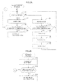
FIG. 2A is a flowchart of a power control process. -
FIG. 2B is a flowchart of an activation process. -
FIG. 3 is a graph illustrating SOC-OCV characteristics of an iron phosphate lithium ion battery. - According to a first aspect of the present invention, an electric storage apparatus includes an output terminal to be electrically connected to a system including an engine, an electric storage device, a monitoring apparatus including a detector and a controller, and a relay disposed between the output terminal and the electric storage device. The detector is configured to detect a variation value corresponding to an amount of charge of the electric storage device. The controller is configured to determine whether the variation value detected by the detector is equal to or lower than an opening threshold, and execute an opening process to switch a state of the relay from a closed state to an open state if the variation value is equal to or lower than the opening threshold. The opening threshold is larger than an engine activation low-threshold by a predetermined value. The engine activation low-threshold is a lowest level of the amount of charge at which the engine is able to be started.
- The electric storage apparatus according to this aspect includes the relay. The relay in the closed state is switched to the open state when the controller determines that the variation value corresponding to the amount of charge of the electric storage device is equal to or lower than the opening threshold. With this configuration, the electric storage apparatus itself can control the amount of charge thereof independently from a system outside the electric storage apparatus so as not to decrease to the level at which the engine cannot be started.
- According to a second aspect of the present invention, in the above-described electric storage apparatus, the controller is further configured to switch a power consumption mode of the monitoring apparatus between a first power consumption mode, in which the monitoring apparatus monitors the electric storage device, and a second power consumption mode, in which the monitoring apparatus consumes less power supplied from the electric storage device than in the first power consumption mode, determine whether the variation value detected by the detector is lower than a low power threshold, and execute a power saving process to switch the power consumption mode of the monitoring apparatus from the first power consumption mode to the second consumption state if the variation value is equal to or lower than the low power threshold. In the first power consumption mode, the monitoring apparatus monitors the electric storage device. In the second power consumption mode, the monitoring apparatus consumes less power supplied from the electric storage device than in the second power consumption mode. With this configuration, the monitoring apparatus consumes less power of the electric storage device.
- According to a third aspect of the present invention, the above-described electric storage apparatus further includes a receiver that is configured to receive a return instruction based on an eternal input. The controller is configured to execute a return process to switch the power consumption mode of the monitoring apparatus from the second power consumption mode back to the first power consumption mode if the receiver receives the return instruction. With this configuration, the monitoring apparatus can monitor the electric storage device again.
- According to a fourth aspect of the present invention, in the above-described electric storage apparatus, the controller is configured to execute a closing process to switch the state of the relay from the open state back to the closed state if the controller executes the return process to switch the power consumption mode of the monitoring apparatus back to the first power consumption mode. With this configuration, the power of the electric storage device can be supplied to the engine again.
- According to a fifth aspect of the present invention, in the above-described electric storage apparatus, the controller is configured to determine whether the engine is started in a period between when the state of the relay is switched back to the closed state and when reference closing time is completed, and execute a re-opening process to switch the state of the relay from the closed state to the open state again if the start of the engine is not determined.
- The charge of the electric storage device starts when the engine is started. However, if a condition in which the engine is not started continues after the state of the relay is switched back to the closed state, the power provided by the electric storage device is consumed by the electric load because the relay is in the closed state, and thus the amount of charge of the electric storage device decreases to the level at which the engine cannot be started. To solve this problem, in the electric storage apparatus, the state of the relay is switched back to the open state if the controller determines that the engine is not started in the period between when the state of the relay is switched back to the closed state and when the reference closing time is completed. With this configuration, the power provided by the electric storage device is less likely to be continuously consumed by the electric load because the relay does not remain in the closed state for a long time while the engine is not started after the relay is switched back to the closed state.
- According to a sixth aspect of the present invention, in the above-described electric storage apparatus, the controller is further configured to determine whether the engine is started in a period between when the power consumption mode is switched back to the first power consumption mode and when reference power time is completed, and execute a re-power saving process to switch the power consumption mode of the monitoring apparatus back to the second power consumption mode if the start of the engine is not determined. In this configuration, a condition in which the engine is not started for a long time after the power consumption mode of the monitoring apparatus is back in the first power consumption mode does not continue, and thus the power of the electric storage device may not be consumed by the controller in the first power consumption mode.
- According to a seventh aspect of the present invention, in the above-described electric storage apparatus, the controller is configured to determine whether a voltage of the electric storage device exceeds an overcharge threshold based on the variation value detected by the detector, and execute an overcharge protection process to switch the state of the relay from the closed state to the open state if the voltage of the electric storage device exceeds the overcharge threshold. With this configuration, the relay can be used to prevent overcharge.
- The technologies described herein can be used in various applications including an electric storage apparatus, a power control method of an electric storage apparatus, a computer program for executing the function of the apparatus or the method, or a recording medium that stores the computer program.
- According to the technology described herein, the electric storage apparatus is configured to control the amount of charge thereof independently from a system outside the electric storage apparatus so as not to decrease to the level at which the engine cannot be started.
- An embodiment will be described with reference to
FIG. 1 to FIG. 3 . - As illustrated in
FIG. 1 , abattery 1 according to this embodiment is a starter battery that supplies power to astarter 3 to start anengine 2. Thebattery 1 is installed in a vehicle such as an engine vehicle or a hybrid vehicle. Thebattery 1 also supplies power to an engine control unit (hereinafter, referred to as an ECU) 4, and an on-vehicle device 5 such as a clock, a light, an audio system, or a security system. Thebattery 1 is charged by analternator 6 that generates power using the rotation of theengine 2. Thebattery 1 is an example of an electric storage apparatus. TheECU 4 or the on-vehicle device 5 is an example of an electric load. - The
battery 1 includes an assembledbattery 11, arelay 12, a battery management system (hereinafter, referred to as BMS) 13, and anoutput terminal 14. The assembledbattery 11 is an example of an electric storage device. The assembledbattery 11 includes cells C that are connected in series. The cell C is a secondary battery that is rechargeable, specifically, an iron phosphate lithium ion battery that has a graphite anode. InFIG. 1 and the description below, the assembledbattery 11 includes four cells C. - The
starter 3, theECU 4, the on-vehicle device 5, and thealternator 6 are electrically connected to theoutput terminal 14. Therelay 12 is provided inside thebattery 1 and is connected between the assembledbattery 11 and theoutput terminal 14. The state of therelay 12 is switched between an open state and a closed state by an opening or closing control of acontroller 22, which will be described later. Therelay 12 is a latching relay. Once therelay 12 is set in the open state or the closed state through an instruction from thecontroller 22, the open state or the closed state is maintained even when the power supply is stopped. In the closed state of therelay 12, thebattery 1 can supply power to thestarter 3, theECU 4, or the on-vehicle device 5, and thebattery 1 can be charged by thealternator 6. In the open state of therelay 12, thebattery 1 cannot supply power to thestarter 3 and the others, and thebattery 1 cannot be charged by thealternator 6. - The
BMS 13 includes avoltage detection circuit 21, thecontroller 22, anactivation switch 23, acommunication unit 24, and four equalization circuits (discharge circuits) 25. TheBMS 13 is an example of a monitoring apparatus. Thevoltage detection circuit 21 is an example of a detector. Thevoltage detection circuit 21 detects the voltage of each cell C and transmits the detected voltage to thecontroller 22. Thevoltage detection circuit 21 may be configured to detect a voltage across the assembledbattery 11. TheBMS 13 may include other detectors in addition to thevoltage detection circuit 21. Examples thereof include a current detector that detects a current flowing through the assembledbattery 11 and a temperature detector that detects a temperature of the assembledbattery 11. TheBMS 13 may be configured to monitor states of the assembledbattery 11 such as an internal resistance or a state of charge (hereinafter, referred to as SOC) based on the detection results. - The
controller 22 includes a central processing unit (hereinafter, referred to as a CPU) 22A and amemory 22B. Thecontroller 22 and thevoltage detection circuit 21 are activated when power is supplied from the assembledbattery 11. Thecontroller 22 is configured to switch a power consumption mode of theBMS 13 among a normal mode, a sleep mode, and a deep sleep mode. In these modes, theBMS 13 consumes power supplied by the assembledbattery 11 at different levels. In other words, thecontroller 22 has a power saving function or a power switching function. - The normal mode is an example of a first power consumption mode of the
BMS 13 while the vehicle is driving. In normal mode, the power is supplied from the assembledbattery 11 to thevoltage detection circuit 21, thecontroller 22, and thecommunication unit 24. This enables theBMS 13 to monitor the state of the assembledbattery 11 such as a voltage of the cell C. - The sleep mode is another example of the first power consumption mode of the
BMS 13 in which theBMS 13 consumes less power than in normal mode. TheBMS 13 is in this power consumption mode while the vehicle is parked and theengine 2 is stopped. Like in the normal mode, in the sleep mode, the power is supplied from the assembledbattery 11 to thevoltage detection circuit 21, thecontroller 22, and thecommunication unit 24. This enables theBMS 13 to monitor the state of the assembledbattery 11. However, in the sleep mode, theBMS 13 monitors the voltage of the cells C in a longer cycle than in the normal mode, for example, by lowering a clock frequency of thecontroller 22. - The deep sleep mode is an example of a second power consumption mode. In deep sleep mode, the
BMS 13 consumes much less power than in the sleep mode. In the deep sleep mode, the power is supplied from the assembledbattery 11 to none of thevoltage detection circuit 21, thecontroller 22, and thecommunication unit 24. This does not enable theBMS 13 to monitor the state of the assembledbattery 11. - The
memory 22B stores various programs for controlling the operation of the controller 22 (including programs for executing a power control process, which will be described later). TheCPU 22A controls each unit of thecontroller 22 in accordance with the program that is read out of thememory 22B. Thememory 22B includes RAM or ROM. Other than the RAM or the ROM, the programs may be stored in a non-volatile memory such as CD-ROM, a hard disc device, or a flush memory. - The
activation switch 23 is an electrical switch such as an FET. Theswitch 23 applies activation signal SG1 to a built-in switch, which is not illustrated, of thecontroller 22 based on an input through an operation by the user. Upon receiving the activation signal SG1 while the power consumption mode is in the deep sleep mode, thecontroller 22 turns on the built-in switch and the current starts to flow. Then, the assembledbattery 11 starts to supply the power again and the power consumption mode of theBMS 13 is back in the normal mode or the sleep mode. In this embodiment, theactivation switch 23 is an example of a receiver and the input through an operation by the user is an example of external input. - The
communication unit 24 receives signals SG2 to SG5, which will be described later, from theECU 4 and inputs the signals SG2 to SG5 to theCPU 22A. Theequalization circuits 25 are connected in parallel to the respective cells C and each include aswitching element 25A and adischarge resistance 25B. Thecontroller 22 closes theswitching element 25A of eachequalization circuit 25 to discharge the power of the cell C, which is connected in parallel to theequalization circuit 25, through thedischarge resistance 25B. - The
controller 22 executes the power control process illustrated inFIG. 2A when the power from the assembledbattery 11 is supplied thereto. Thecontroller 22 determines whether theengine 2 is stopped (S1). TheECU 4 transmits a lock signal SG3, an accessory signal SG4, an ignition-on signal SG5, or an engine activation signal SG2 to thecommunication unit 24 according to a position of an ignition switch, i.e., a lock position, an accessory position, an ignition-on position, or a start position, respectively. - The
controller 22 determines that theengine 2 is stopped if the signal received by thecommunication unit 24 is the lock signal SG3 or the accessory signal SG4. If the signal received by thecommunication unit 24 after the engine activation signal SG2 is the ignition-on signal SG5, thecontroller 22 determines that theengine 2 is running. If thebattery 1 is installed in an idling stop vehicle, theengine 2 of which is temporary stopped during driving, thecontroller 22 may be configured to determine that theengine 2 is stopped or determine that theengine 2 is running because the stop is temporary when thecommunication unit 24 receives an engine temporary stop signal from theECU 4. - If the
engine 2 is running (NO in step S1), thecontroller 22 switches the power consumption mode of theBMS 13 to the normal mode (S2). Specifically, if theBMS 13 is in the normal mode, thecontroller 22 maintains the normal mode, and if theBMS 13 is in another mode, thecontroller 22 switches the mode to the normal mode. In the normal mode, therelay 12 is usually in the closed state. - The
ECU 4 executes a charge control if the SOC of the assembledbattery 11 decreases to the level that corresponds to a charge start SOC, at which the charging of the assembledbattery 11 is started, while theengine 2 is running. In the charge control, the assembledbattery 11 is charged by the power generated by thealternator 6 and the charging ends when the SOC reaches a level that corresponds to a charge stop SOC (about 99%). As illustrated inFIG. 3 , in the iron phosphate lithium ion battery, a region of about 75% to about 100% of SOC is a flat region (plateau) in which a change rate of an open circuit voltage (hereinafter, referred to as OCV) is relatively low, and it is difficult to accurately estimate an SOC from the OCV. In contract, a region of about 55% to 70% of SOC is a variation region in which the change rate of the OCV is higher than the flat region, and an SOC can be accurately estimated from the OCV. In this embodiment, the charge start SOC is set at about 60% (refer to a charge control region inFIG. 3 ). - The
controller 22 executes an overcharge protection process (S3 to S6) after thecontroller 22 switches the power consumption mode of theBMS 13 to the normal mode. In the overcharge protection process, based on a detection result of thevoltage detection circuit 21, thecontroller 22 determines whether a cell voltage Vc of at least one of the cells C is higher than an overcharge threshold Vth2 (S3). If cell voltages Vc of all the cells C are lower than the overcharge threshold Vth2 (NO in step S3), the cells C are in a normal state, and thecontroller 22 returns to step S1. If thecontroller 22 determines that the cell voltage Vc of at least one of the cells C is equal to or higher than the overcharge threshold Vth 2 (YES in step S3), the at least one cell C is in an overcharged state, and thecontroller 22 proceeds to the next overcharge protection steps (S4 to S6). - The
controller 22 switches the state of therelay 12 to the open state to stop the charge by the alternator 6 (S4), and executes equalization (S5). Thecontroller 22 closes theswitch element 25A of theequalization circuit 25 that is connected in parallel to the cell C that is in the overcharged state to reduce the cell voltage Vc thereof to the same level as the cell voltage Vc of the other cells C. - After the equalization, the
controller 22 executes a return process to switch the state of therelay 12 to the closed state again (S6). Then, thecontroller 22 returns to step S1. In this configuration, therelay 12 can be used for the overcharge protection. TheECU 4 preferably supplies the power generated by thealternator 6 to the on-vehicle device 5 or other devices while therelay 12 is opened. Thecontroller 22 may execute the equalization (S5) before step S4, or may not execute the equalization (S5). - In step S1, if the
controller 22 determines that theengine 2 is stopped (YES in step S1), thecontroller 22 switches the power consumption mode of theBMS 13 to the sleep mode (S7). Specifically, if theBMS 13 is in the sleep mode, thecontroller 22 maintains the sleep mode, and if theBMS 13 is in the other mode, thecontroller 22 switches the mode to the sleep mode. Like in the normal mode, in the sleep mode, therelay 12 is usually in the closed state. This allows the power supply from the assembledbattery 11 to the on-vehicle device 5 or other devices, but the assembledbattery 11 is not charged. Accordingly, the SOC decreases due to self-discharge, power consumption by theBMS 13 or the on-vehicle device 5, or the dark current. - In this step, variations in the cell voltages Vc of the cells C are relatively small because the
engine 2 is stopped and theBMS 13 is in the sleep mode. Therefore, the cell voltages Vc are substantially in proportion to the OCV. Accordingly, thecontroller 22 can estimate the OCV or the SOC of each cell based on the cell voltage Vc of each cell C. - After the
controller 22 switches the power consumption mode of theBMS 13 to the sleep mode, based on the detection result of thevoltage detection circuit 21, thecontroller 22 determines whether the cell voltage Vc of at least one of the cells C is equal to or lower than a power-saving threshold Vth1 (an example of a low power threshold and an opening threshold) (S8). The power-saving threshold Vth1 is larger than an engine activation low-threshold Vth3. Specifically, the power-saving threshold Vth1 is obtained by adding a predetermined value to the engine activation low-threshold Vth3. The engine activation low-threshold Vth3 is an OCV that corresponds to the lowest level of the SOC at which theengine 2 can be started (the lowest SOC). For example, the predetermined value is less than 1.0 V, less than 0.5 V, or less than 0.1 V. - The
controller 22 may be configured to determine whether the cell voltage Vc of each of the cells C is equal to or lower than the power-saving threshold Vth1, or whether a lowest cell voltage of the cell voltages Vc of the cells C is equal to or lower than the power-saving threshold Vth1. Thecontroller 22 may be configured to determine whether the cell voltage Vc of at least one of the cells C is between the power-saving threshold Vth1 and the engine activation low-threshold Vth3. In addition, thecontroller 22 may be configured to determine whether the total voltage of the assembled battery 11 (the total of the cell voltages Vc of all the cells C), instead of the cell voltage Vc of each cell C, is lower than the opening threshold in step S8. - As indicated in
FIG. 3 , in an engine startable region (20% to 100% of SOC) of the iron phosphate lithium ion battery, the region of about 40% to 50% of the SOC is the flat region, and the region of about 20% to 35% of the SOC is the variation region. The power-saving threshold Vth1 is preferably set in this variation region. In this embodiment, the power-saving threshold Vth1 is set at the OCV (about 3.28 V) that corresponds to about 30% of the SOC. Hereinafter, such an SOC is referred to as the power saving SOC. - In step S8, if the
controller 22 determines that the cell voltages Vc of all the cells C are higher than the power-saving threshold Vth1 (NO in step S8), the SOC of each cell C is at a level at which theengine 2 can be started. Then, thecontroller 22 returns to step S1. In contrast, if thecontroller 22 determines that the cell voltage Vc of at least one of the cells C is equal to or lower than the power-saving threshold Vth1 (YES in step S8), the SOC of the cell C may be close to the lowest SOC at which theengine 2 cannot be started. Therefore, thecontroller 22 switches the state of therelay 12 to the open state and switches the power consumption mode of theBMS 13 to the deep sleep mode (S9). Accordingly, the power is not supplied from the assembledbattery 11 to thecontroller 22 and thecommunication unit 24. - In step S9, the timing of the opening of the
relay 12 and the timing of switching the power consumption mode of theBMS 13 to the deep sleep mode may be or may not be the same. For example, thecontroller 22 may switch the power consumption mode of theBMS 13 to the deep sleep mode after the opening of therelay 12. - When step S9 is performed, the power supply from the assembled
battery 11 to the on-vehicle device 5 or other devices stops. With this configuration, the power consumption of the assembledbattery 11 is reduced. As a result, after the cell voltage Vc becomes equal to or lower than the power saving threshold Vth1, the SOC of the cell C decreases toward the lowest SOC more slowly than that of a cell in a battery with a configuration in which step S9 is not performed. In other words, the SOCs of the cells C remain in the engine startable region for a longer period of time and the battery hardly runs out. - Since the
ECU 4 executes the charge control as described above, the SOC of the assembledbattery 11 is not always maintained at about 100% during the driving of the vehicle. In some cases, the SOC may decrease to about 60% immediately after theengine 2 is stopped (refer to an engine stopped region inFIG. 3 , in which a vehicle is parked). Accordingly, thebattery 1 of this embodiment is particularly useful compared to the configuration in which theECU 4 always charges the assembledbattery 11 to full capacity during the driving of the vehicle. - Experiments were conducted under the following conditions: the power consumption of the assembled
battery 11 due to the self-discharge was about 1 mA/day in terms of current; the power consumption of theBMS 13 in the sleep mode was about 1 mA/day in terms of current; and the power consumption of the on-vehicle device 5 was about 15 mA/day in terms of current. Further, the SOC at the time when theengine 2 was stopped was 60%, the SOC corresponding to the power-saving threshold Vth1 was 30%, and the lowest SOC was 20%. In a comparative example in which a controller did not execute the processes in step S9, the SOC of the cell C decreased to the lowest SOC on 47th day after theengine 2 was stopped. In contrast, thecontroller 22 of this embodiment executed step S9 on about 35th day after theengine 2 was stopped, and then the SOC of the cell C decreased to the lowest SOC on about 114th day. As apparent from this example, the SOC of the cell C in this embodiment took a longer time to reach the lowest SOC by more than 100 days than the comparative example without the processes in S9. - In the iron phosphate lithium ion battery, if the SOC of the cell C is in an engine unstartable region (for example, 0% to 20% of SOC, refer to
FIG. 3 ), the battery goes dead, and if the SOC is lower than 0, the battery may not be reused. Step S8 and step S9 are examples of the opening process and the power saving process. The SOC in the engine unstartable region or other regions differ depending on types of vehicle or environments. - If the
activation switch 23 is turned on when theBMS 13 is in the deep sleep mode and the power is not supplied to thecontroller 22, the current starts flowing through thecontroller 22 and the power is supplied from the assembledbattery 11 to thecontroller 22 again. Thecontroller 22 executes an activation process illustrated inFIG. 2B . Theengine 2 is more likely to start shortly after theactivation switch 23 of the battery is turned on, and thus thecontroller 22 switches the state of therelay 12 back to the closed state and switches the power consumption mode of theBMS 13 back to the sleep mode (S11). - In step S11, the timing of the closing the
relay 12 and the timing of the switching back of theBMS 13 to the sleep mode may be or may not be the same. For example, thecontroller 22 may switch the state of therelay 12 to the closed state after switching the power consumption mode of theBMS 13 back to the sleep mode. - The processes in step S11 allow the assembled
battery 11 to be back in the state that can supply the power to the on-vehicle device 5 and allow theBMS 13 to be back in the state that can monitor the assembledbattery 11 before theengine 2 starts. In other words, even if theBMS 13 is in the deep sleep mode and not monitoring the assembledbattery 11, upon receiving the return instruction, theBMS 13 can be back in the sleep mode or the other mode that can monitor the assembledbattery 13. Accordingly, while the vehicle is parked, theBMS 13 can be in the deep sleep mode to reduce the power consumption without any problems. - Subsequently, the
controller 22 determines whether theengine 2 is started in a period between when the mode of theBMS 13 is switched back to the sleep mode or the other mode and when waiting time (an example of reference closing time or reference power time) is completed (S12). If thecontroller 22 receives the engine activation signal SG2 before the waiting time is completed, thecontroller 22 determines that theengine 2 is started (YES in step 12) and thecontroller 22 returns to step S1 inFIG. 2A . Then, thecontroller 22 proceeds to step S2, and thus the assembledbattery 11 is charged by thealternator 6. - If the
controller 22 does not receive the engine activation signal SG2 by the end of the waiting time, thecontroller 22 determines that theengine 2 is not started (NO in step S12). Thecontroller 22 switches the state of therelay 12 to the open state again and switches the power consumption mode of theBMS 13 to the deep sleep mode again (S13). With this configuration, the power provided by the assembledbattery 11 is less likely to be continuously consumed by the on-vehicle device 5 or theBMS 13 because therelay 12 does not remain in the closed state for a long time while theengine 2 is not started after therelay 12 is switched back to the closed state. Therefore, thebattery 1 is less likely to be dead. - According to this embodiment, the
battery 1 includes therelay 12 and theBMS 13 therein in addition to the assembledbattery 11. TheBMS 13 controls the opening and the closing of therelay 12. With this configuration, thebattery 1 can control itself independently from systems installed in a vehicle body, i.e., systems other thanBMS 13 in the vehicle, so as not to run out. In comparison to a configuration in which therelay 12 is provided in anywhere in the vehicle other than inside thebattery 1, therelay 12 is less likely to be out of control due to communication errors between thebattery 1 and the other system. - The present invention is not limited to the embodiment described above and illustrated in the drawings. The following various embodiments are also included in the technical scope of the present invention.
- The electric storage device is not limited to the electric storage device that includes the cells connected in series, but may be an electric storage device that includes cells connected in parallel. The number of the cells may suitably be changed. The electric storage device is not limited to the assembled
battery 11, but may include a single cell. The electric storage device is not limited to the iron phosphate lithium ion battery that has a graphite anode. The electric storage device may be other non-aqueous electrolyte secondary batteries such as a manganese lithium ion battery, or other batteries than the non-aqueous electrolyte secondary battery such as a lead electric storage battery or a nickel metal hydride battery. Further, the electric storage device is not limited to the secondary battery, but may be a capacitor. The electric storage device may be any battery that is used to start an engine of a machine provided with an engine (internal combustion engine, for example) as a driving source. For example, the machine may be an aircraft or a machine tool in addition to the vehicle. - The second power consumption mode may be a mode in which the assembled
battery 11 supplies the power to at least one of thevoltage detection circuit 21, thecontroller 22, and thecommunication unit 24. For example, in the deep sleep mode, the power may be supplied to thecontroller 22 and thecommunication unit 24, and the power may not be supplied to thevoltage detection circuit 21. In such a case, thecontroller 22 may stop the monitoring of the voltage of the cell C and stop the opening or closing of therelay 12, and may be only capable of determining whether thecommunication unit 24 receives the input signal from outside. Thecontroller 22 may switch the power consumption mode of theBMS 13 back to the sleep mode or the normal mode when thecommunication unit 24 receives the input signal. - Specifically, if the power is supplied from a power source other than the assembled
battery 11 to theECU 4 and theECU 4 can output the signals such as the ignition-on signal SG5 to thecommunication unit 24 with therelay 12 in the open state, thecontroller 22 can determine that the return instruction is received when thecommunication unit 24 receives the ignition-on signal SG5. Theengine 2 is more likely to start when a driver turns the ignition switch to the ignition-on position. In this configuration, thecommunication unit 24 is an example of a receiver. Thecommunication unit 24 may be configured to receive the return instruction via wire communication or via wireless communication. For example, thecommunication unit 24 may be configured to receive the return instruction based on radio transmissions from a remote control switch operated by the driver. Thecontroller 22 may determine that the return instruction is received upon receiving the accessory signal SG4. - In the above configuration in which the power can be supplied to the
controller 22 and thecommunication unit 22 in the deep sleep mode, in step S9, thecontroller 22 may switch the state of therelay 12 to the open state after thecontroller 22 switches the power consumption mode of theBMS 13 to the deep sleep mode. Further, in step S11, thecontroller 22 may switch the power consumption mode of theBMS 13 back to the sleep mode or the normal mode after thecontroller 22 switches the state of therelay 12 back to the closed state. - In the above configuration in which the power can be supplied to the
controller 22 and thecommunication unit 22 in the deep sleep mode, the waiting time may be set longer for the case where thecontroller 22 receives the activation signal SG1 than for the case where thecontroller 22 receives the ignition-on signal SG5 or the accessory signal SG4. This is based on the assumption that a longer time is required if thecontroller 22 receives the activation signal SG1, because, after turning on theactivation switch 23 of thebattery 1, the driver needs to come back from the position where thebattery 1 is installed to the driver's seat to turn the ignition switch to the start position. - As described above, the receiver may be configured to receive the return instruction based on the input signal from the
communication unit 24, or may be configured to receive the return instruction based on the human-operated input using theactivation switch 23. Theactivation switch 23 may be a mechanical switch and may be configured to be switched between the open state and closed state by an operation of the user. When theactivation switch 23 is switched to the closed state, the power starts to be supplied from the assembledbattery 11 to thecontroller 22 again, and the power consumption mode of theBMS 13 is switched back to the normal mode or the sleep mode. - In the above embodiment, the
controller 22 including oneCPU 22A and thememory 22B is described as an example of a controller. However, the controller is not limited to this. The controller may include a plurality of CPUs or may include a hard circuit such as an ASIC (Application Specific Integrated Circuit) or may include both of the hard circuit and the CPU. For example, the controller may execute some processes or all of the processes of the power control process by different CPUs or hard circuits. The order of the steps inFIGS. 2A, 2B may be suitably changed. - In the above embodiment, the low power threshold or the opening threshold are the same power-saving threshold Vth1. However, the present technology is not limited to this. The low power threshold and the opening threshold may differ from each other. Specifically, in step S8 and step S9, the
controller 22 may compare the cell voltage Vc of each cell C to the opening threshold in addition to the power-saving threshold Vth1. Thecontroller 22 may be configured to switch the power consumption mode of theBMS 13 to the deep sleep mode when determining that at least one of the cells C has the cell voltage Vc that is lower than the power-saving threshold Vth1, and to switch the state of therelay 12 to the open state when determining that at least one of the cells C has the cell voltage Vc that is lower than the opening threshold. - In the above embodiment, the reference closing time and the reference power time are the same waiting time. However, the present technology is not limited to this. The reference closing time and the reference power time may differ from each other. Specifically, in step S12 and step S13, the
controller 22 may determine whether a first waiting time and a second waiting time that are different from each other elapse from the time when theBMS 13 is back in the sleep mode or the other mode. If thecontroller 22 determines that theengine 2 does not start by the end of the first waiting time, thecontroller 22 may switch the state of therelay 12 to the open state again. If thecontroller 22 determines that theengine 2 does not start by the end of the second waiting time, thecontroller 22 may switch the power consumption mode of theBMS 13 to the deep sleep mode again. - The
controller 22 may be configured to determine whether theengine 2 is stopped based on the voltage or the current of the assembledbattery 11 in step S1. For example, thecontroller 22 may determine that theengine 2 is stopped if thecontroller 22 determines that a variation amount of the voltage of the assembledbattery 11 continues to be lower than a reference value for a predetermined time. - In the above embodiment, in S8 or other steps, the
controller 22 determines about the SOC based on the voltage Vc of the cell C. However, the present technology is not limited to this. Thecontroller 22 may determine about the SOC based on a variable element that has a correlation with the SOC. For example, the variable element is a current accumulated amount that is obtained by integrating charge and discharge currents over time. In other words, thecontroller 22 may have any configuration that can execute the process in step S8 based on the variation value corresponding to the amount of charge of the assembledbattery 11. - The
controller 22 may not be configured to switch the power consumption mode of theBMS 13 to the sleep mode in step S9. Even in such a configuration, theBMS 13 consumes less power of the assembledbattery 11.
Claims (7)
- An electric storage apparatus comprising:an output terminal configured to be electrically connected to a system including an engine;an electric storage device:a monitoring apparatus including a detector and a controller, the detector being configured to detect a variation value corresponding to an amount of charge of the electric storage device; anda relay disposed between the output terminal and the electric storage device, whereinthe controller is configured to:determine whether the variation value detected by the detector is equal to or lower than an opening threshold, the opening threshold being larger than an engine activation low-threshold by a predetermined value, the engine activation low-threshold being a lowest level of the amount of charge at which the engine is able to be started; andexecute an opening process to switch a state of the relay from a closed state to an open state if the variation value is equal to or lower than the opening threshold.
- The electric storage apparatus according to claim 1, wherein
the controller is further configured to:switch a power consumption mode of the monitoring apparatus between a first power consumption mode, in which the monitoring apparatus monitors the electric storage device, and a second power consumption mode, in which the monitoring apparatus consumes less power supplied from the electric storage device than in the first power consumption mode;determine whether the variation value detected by the detector is lower than a low power threshold; andexecute a power saving process to switch the power consumption mode of the monitoring apparatus from the first power consumption mode to the second consumption state if the variation value is equal to or lower than the low power threshold. - The electric storage apparatus according to claim 2, further comprising a receiver configured to receive a return instruction based on an eternal input apparatus, wherein
the controller is configured to execute a return process to switch the power consumption mode of the monitoring apparatus from the second power consumption mode back to the first power consumption mode if the receiver receives the return instruction. - The electric storage apparatus according to claim 3, wherein the controller is configured to execute a closing process to switch the state of the relay from the open state back to the closed state if the controller executes the return process to switch the power consumption mode of the monitoring apparatus back to the first power consumption mode.
- The electric storage apparatus according to claim 4, wherein the controller is configured to:determine whether the engine is started in a period between when the state of the relay is switched back to the closed state and when reference closing time is completed, andexecute a re-opening process to switch the state of the relay from the closed state to the open state again if the start of the engine is not determined.
- The electric storage apparatus according to any one of claims 3 to 5, wherein the controller is further configured to:determine whether the engine is started in a period between when the power consumption mode is switched back to the first power consumption mode and when reference power time is completed; andexecute a re-power saving process to switch the power consumption mode of the monitoring apparatus back to the second power consumption mode if the start of the engine is not determined .
- The electric storage apparatus according to any one of claims 1 to 6, wherein the controller is configured to:determine whether a voltage of the electric storage device exceeds an overcharge threshold based on the variation value detected by the detector; andexecute an overcharge protection process to switch the state of the relay from the closed state to the open state if the voltage of the electric storage device exceeds the overcharge threshold.
Applications Claiming Priority (2)
| Application Number | Priority Date | Filing Date | Title |
|---|---|---|---|
| JP2012225832 | 2012-10-11 | ||
| JP2013187835A JP6234127B2 (en) | 2012-10-11 | 2013-09-11 | Power storage device |
Publications (3)
| Publication Number | Publication Date |
|---|---|
| EP2720309A2 true EP2720309A2 (en) | 2014-04-16 |
| EP2720309A3 EP2720309A3 (en) | 2014-09-24 |
| EP2720309B1 EP2720309B1 (en) | 2018-12-05 |
Family
ID=49322266
Family Applications (1)
| Application Number | Title | Priority Date | Filing Date |
|---|---|---|---|
| EP13187826.6A Active EP2720309B1 (en) | 2012-10-11 | 2013-10-09 | Electric storage apparatus |
Country Status (6)
| Country | Link |
|---|---|
| US (5) | US9165736B2 (en) |
| EP (1) | EP2720309B1 (en) |
| JP (1) | JP6234127B2 (en) |
| KR (1) | KR102021155B1 (en) |
| CN (2) | CN108011433B (en) |
| DE (2) | DE202013012142U1 (en) |
Cited By (6)
| Publication number | Priority date | Publication date | Assignee | Title |
|---|---|---|---|---|
| GB2548786A (en) * | 2015-12-30 | 2017-10-04 | Hyperdrive Innovation Ltd | Battery management system |
| CN107499138A (en) * | 2017-07-24 | 2017-12-22 | 广州小鹏汽车科技有限公司 | A kind of power control method and system of electric automobile central control system |
| CN108695566A (en) * | 2017-04-05 | 2018-10-23 | 广东广晟通信技术有限公司 | A kind of synchronous control system framework promoting energy-saving efficiency |
| EP3598600A4 (en) * | 2017-04-12 | 2020-01-22 | LG Chem, Ltd. | DEVICE AND METHOD FOR PREVENTING AND REUSE OF AN OVERLOAD OF AN ENERGY STORAGE DEVICE |
| CN112186279A (en) * | 2020-09-30 | 2021-01-05 | 宁波新舜信息科技有限公司 | Power management system with dormancy activation function |
| US11961977B2 (en) | 2015-12-30 | 2024-04-16 | Turntide Drives Limited | Battery management system |
Families Citing this family (51)
| Publication number | Priority date | Publication date | Assignee | Title |
|---|---|---|---|---|
| JP6234127B2 (en) * | 2012-10-11 | 2017-11-22 | 株式会社Gsユアサ | Power storage device |
| KR102082866B1 (en) * | 2013-04-18 | 2020-04-14 | 삼성에스디아이 주식회사 | Battery management system and driving method thereof |
| JP6107562B2 (en) | 2013-09-19 | 2017-04-05 | 株式会社豊田自動織機 | Battery control unit system |
| EP3216078B1 (en) | 2014-11-04 | 2021-07-21 | CPS Technology Holdings LLC | Modular design of a 48-volt li-ion battery for ease of assembly and disassembly |
| US10388995B2 (en) * | 2015-03-25 | 2019-08-20 | Gs Yuasa International Ltd. | Monitoring apparatus for energy storage device, energy storage apparatus, and a method of monitoring energy storage device |
| JP6489366B2 (en) * | 2015-05-26 | 2019-03-27 | 株式会社Gsユアサ | A battery pack monitoring device and battery pack capacity equalization method. |
| CN107848104B (en) * | 2015-07-31 | 2021-07-09 | 工机控股株式会社 | electrical tools |
| CN105128783B (en) * | 2015-09-22 | 2017-03-29 | 华晨汽车集团控股有限公司 | A kind of distributed energy of electric automobile regulates and controls method |
| CN106556800B (en) * | 2015-09-24 | 2019-06-11 | 华为技术有限公司 | A method and device for battery detection |
| KR101744712B1 (en) | 2015-12-10 | 2017-06-08 | 현대오트론 주식회사 | Apparatus and method for preventing over-charging |
| JP2017136901A (en) | 2016-02-02 | 2017-08-10 | 株式会社Gsユアサ | Battery device, vehicle, automatic vehicle |
| JP6769046B2 (en) * | 2016-03-01 | 2020-10-14 | 株式会社Gsユアサ | Power storage element monitoring device, power storage element module, SOC estimation method |
| CN107332292B (en) * | 2016-04-29 | 2021-02-26 | 华为技术有限公司 | Voltage acquisition circuit and circuit control method |
| JP6515875B2 (en) * | 2016-06-10 | 2019-05-22 | 株式会社デンソー | Automotive power system |
| JP6755136B2 (en) * | 2016-07-13 | 2020-09-16 | 株式会社デンソーテン | Voltage detector and voltage detection method |
| CN105958142A (en) * | 2016-07-14 | 2016-09-21 | 成都有米科技有限公司 | Electromechanical-hybrid-based servo storage battery automation protection device and method |
| JP6807018B2 (en) * | 2016-10-03 | 2021-01-06 | 株式会社Gsユアサ | Power storage device for vehicles and vehicles |
| CN107681707A (en) * | 2016-10-17 | 2018-02-09 | 深圳市东方之星电源有限公司 | A kind of automobile and automobile power supply system dormancy control circuit |
| EP3316385B1 (en) * | 2016-10-26 | 2019-04-17 | Samsung SDI Co., Ltd. | Battery system with internally powered real time clock, power supply circuit for a real time clock and method for operating a real time clock of a battery system |
| CN106515455B (en) * | 2016-11-30 | 2018-10-02 | 成都雅骏新能源汽车科技股份有限公司 | A kind of vehicle pattern switching strategy suitable for pure electric vehicle logistic car |
| JP6965560B2 (en) * | 2017-05-09 | 2021-11-10 | コニカミノルタ株式会社 | Medical diagnostic imaging equipment |
| KR102348118B1 (en) * | 2017-06-15 | 2022-01-07 | 현대자동차주식회사 | Apparatus for controlling dark current of vehicle and method thereof |
| EP3709471B1 (en) * | 2017-11-10 | 2023-12-20 | Kabushiki Kaisha Toshiba | Storage battery system, method, and program |
| DE102017011040A1 (en) * | 2017-11-29 | 2019-05-29 | Iie Gmbh & Co. Kg | Electrical system |
| JP7024463B2 (en) | 2018-02-01 | 2022-02-24 | 株式会社Gsユアサ | Management device, power storage device, management method of power storage element |
| JP7008265B2 (en) | 2018-04-17 | 2022-01-25 | 株式会社Gsユアサ | Management method of power storage device and power storage element |
| CN108627773B (en) * | 2018-05-04 | 2022-05-24 | 深圳市道通智能航空技术股份有限公司 | Battery power consumption control method and device and unmanned aerial vehicle |
| CN108839624B (en) * | 2018-06-28 | 2020-10-30 | 潍柴动力股份有限公司 | Automobile ignition switch control system and method |
| JP7056513B2 (en) * | 2018-10-26 | 2022-04-19 | トヨタ自動車株式会社 | Battery control device |
| KR102711058B1 (en) * | 2018-11-12 | 2024-09-27 | 주식회사 엘지에너지솔루션 | Method for eliminating voltage imbalance between battery modules connected in series and battery pack to which the method is applied |
| JP7284911B2 (en) * | 2019-03-06 | 2023-06-01 | 株式会社Gsユアサ | Storage device management device, system, and storage device management method |
| CN113544927A (en) | 2019-03-22 | 2021-10-22 | 株式会社杰士汤浅国际 | Power storage element management device and power storage device |
| JP7156150B2 (en) * | 2019-04-16 | 2022-10-19 | トヨタ自動車株式会社 | Drive system controller |
| JP7115409B2 (en) * | 2019-04-19 | 2022-08-09 | トヨタ自動車株式会社 | Drive system controller |
| WO2021010007A1 (en) * | 2019-07-17 | 2021-01-21 | パナソニックIpマネジメント株式会社 | Power cutoff device |
| US11271256B2 (en) | 2020-01-10 | 2022-03-08 | Lg Energy Solution, Ltd. | Externally mode-switchable battery pack and method for externally switching mode of battery pack |
| CN113212329B (en) * | 2020-01-21 | 2024-05-17 | 广州汽车集团股份有限公司 | Vehicle power control method, power controller and power control system |
| CN111537901B (en) * | 2020-04-09 | 2022-06-17 | 浙江南都电源动力股份有限公司 | Battery power state measuring and calculating method, battery pack and vehicle |
| US12024056B2 (en) * | 2020-08-21 | 2024-07-02 | Hyundai Motor Company | Method and apparatus for managing shared personal mobility vehicle |
| JP7380535B2 (en) * | 2020-11-19 | 2023-11-15 | トヨタ自動車株式会社 | Battery monitoring device, method, program, and vehicle |
| EP4270703A4 (en) * | 2020-12-28 | 2024-03-27 | Dongguan Poweramp Technology Limited | ELECTROCHEMICAL LONG STANDBY DEVICE, ENERGY STORAGE SYSTEM AND ELECTRIC VEHICLE |
| JP7746685B2 (en) * | 2021-05-13 | 2025-10-01 | 株式会社Gsユアサ | Control method for power storage device and current interruption device |
| WO2022262139A1 (en) * | 2021-06-18 | 2022-12-22 | 武汉领普科技有限公司 | Power supply circuit, and sensing device and application thereof |
| JP7705308B2 (en) * | 2021-08-31 | 2025-07-09 | 株式会社Subaru | vehicle |
| KR102954622B1 (en) * | 2021-09-07 | 2026-04-20 | 컨템포러리 엠퍼렉스 테크놀로지 (홍콩) 리미티드 | Over-discharge protection method and system, vehicle, battery management system and storage medium |
| US11932268B2 (en) * | 2022-05-27 | 2024-03-19 | Plusai, Inc. | Methods and apparatus for tamper detection of a vehicle system |
| CN115333201B (en) * | 2022-08-30 | 2024-09-03 | 重庆长安新能源汽车科技有限公司 | TBOX chip backup battery power management method, control system and storage medium |
| DE102022212625A1 (en) | 2022-11-25 | 2024-05-29 | Robert Bosch Gesellschaft mit beschränkter Haftung | Electrical energy storage |
| CN116101126A (en) * | 2023-03-07 | 2023-05-12 | 珠海冠宇动力电源有限公司 | Battery system and car |
| WO2026003958A1 (en) * | 2024-06-25 | 2026-01-02 | 株式会社オートネットワーク技術研究所 | Onboard control device |
| WO2026057783A1 (en) * | 2024-09-13 | 2026-03-19 | Jt International Sa | An aerosol generating device |
Citations (1)
| Publication number | Priority date | Publication date | Assignee | Title |
|---|---|---|---|---|
| JP2006327487A (en) | 2005-05-27 | 2006-12-07 | Fujitsu Ten Ltd | Vehicle control device and method |
Family Cites Families (43)
| Publication number | Priority date | Publication date | Assignee | Title |
|---|---|---|---|---|
| US5332958A (en) | 1986-12-12 | 1994-07-26 | Sloan Jeffrey M | Battery disconnect device |
| US4902956A (en) * | 1986-12-12 | 1990-02-20 | Sloan Jeffrey M | Safety device to prevent excessive battery drain |
| DE4019478A1 (en) | 1989-06-20 | 1991-01-10 | Honda Motor Co Ltd | ELECTRIC POWER SUPPLY CONTROL UNIT FOR A MOTOR VEHICLE |
| US5343351A (en) * | 1991-11-18 | 1994-08-30 | Electro-Tech, Inc. | Starter motor protection circuit with relay protection |
| US5381295A (en) * | 1991-12-12 | 1995-01-10 | Datamax Electronics, Inc. | Resetable battery drain limitation circuit with improved latching relay |
| US5327068A (en) * | 1992-07-01 | 1994-07-05 | Peerless Innovations, Inc. | Battery protection system |
| DE4337792C2 (en) | 1993-11-05 | 2003-03-13 | Bosch Gmbh Robert | Multi-function control device for a motor vehicle |
| AU724292C (en) | 1995-06-21 | 2001-10-11 | Batteryguard Limited | Battery monitor |
| JP3374360B2 (en) | 1996-08-28 | 2003-02-04 | 矢崎総業株式会社 | Vehicle battery power supply method and vehicle battery power supply device |
| JPH10322930A (en) * | 1997-05-22 | 1998-12-04 | Yazaki Corp | Vehicle power supply method and vehicle power supply device |
| US5963018A (en) * | 1997-09-08 | 1999-10-05 | Exide Batteries Ltd. | Automobile batteries with inherent immobilizers |
| JP3830243B2 (en) | 1997-10-06 | 2006-10-04 | トヨタ自動車株式会社 | Battery power supply |
| JP3570665B2 (en) * | 1998-05-27 | 2004-09-29 | 矢崎総業株式会社 | Battery rise prevention device |
| JP2000041342A (en) * | 1998-07-21 | 2000-02-08 | Shin Caterpillar Mitsubishi Ltd | Electric circuit for battery |
| DE19941513A1 (en) | 1999-08-31 | 2001-03-01 | Stefan Maier | Regulator device for electrical energy consumption in motor vehicles has detector unit for battery charge condition and control unit to stop energy take-up when battery charge is at set condition |
| JP2001268787A (en) * | 2000-01-13 | 2001-09-28 | Toyota Motor Corp | Power circuit |
| US6712923B2 (en) | 2000-01-12 | 2004-03-30 | Toyota Jidosha Kabushiki Kaisha | Manufacturing apparatus and manufacturing method of solid polymer film with catalyst deposited thereon |
| CN2590190Y (en) * | 2000-04-10 | 2003-12-03 | 詹立英 | Password recognition theft-proof battery |
| JP4693290B2 (en) | 2001-07-06 | 2011-06-01 | 矢崎総業株式会社 | Battery rise prevention device |
| JP4693291B2 (en) | 2001-07-06 | 2011-06-01 | 矢崎総業株式会社 | Battery rise prevention device |
| JP2004168263A (en) * | 2002-11-22 | 2004-06-17 | Yazaki Corp | Battery SOC detection method and device, battery power supply control method and device |
| JP4211715B2 (en) * | 2004-08-23 | 2009-01-21 | 株式会社デンソー | In-vehicle power supply system |
| US7146959B2 (en) * | 2004-12-28 | 2006-12-12 | Detroit Diesel Corporation | Battery voltage threshold adjustment for automatic start and stop system |
| JP2006296085A (en) | 2005-04-11 | 2006-10-26 | Furukawa Electric Co Ltd:The | Vehicle power management device and power management system |
| JP5050325B2 (en) * | 2005-07-12 | 2012-10-17 | 日産自動車株式会社 | Battery control device |
| JP2007078443A (en) | 2005-09-13 | 2007-03-29 | Yazaki Corp | Battery state detection device |
| EP1780867B1 (en) * | 2005-10-28 | 2016-11-30 | Black & Decker Inc. | Battery pack for cordless power tools |
| JP4875368B2 (en) | 2006-01-26 | 2012-02-15 | 古河電気工業株式会社 | Vehicle power distribution system |
| JP2007203929A (en) * | 2006-02-02 | 2007-08-16 | Auto Network Gijutsu Kenkyusho:Kk | Dark current measuring device for vehicle and power supply control device for vehicle |
| JP5091473B2 (en) | 2006-12-14 | 2012-12-05 | パナソニック株式会社 | Battery pack control method, battery pack control circuit, charging circuit including the battery pack, and battery pack |
| JP5517398B2 (en) * | 2007-03-15 | 2014-06-11 | 三菱重工業株式会社 | Power storage system |
| US20090147427A1 (en) | 2007-09-24 | 2009-06-11 | Yeshaiahou Aharon Levinas | Battery disconnect device |
| US7986055B2 (en) | 2008-01-22 | 2011-07-26 | Honda Motor Co., Ltd. | Adjustment of control strategy based on temperature |
| JP5238431B2 (en) * | 2008-09-26 | 2013-07-17 | 本田技研工業株式会社 | Vehicle load control device |
| CN102202929B (en) | 2008-10-31 | 2014-01-01 | 丰田自动车株式会社 | Electric power source system for electrically driven vehicle and its control method |
| JP5493407B2 (en) * | 2009-03-17 | 2014-05-14 | 日産自動車株式会社 | Battery pack capacity adjustment device |
| JP2011108537A (en) * | 2009-11-19 | 2011-06-02 | Nippon Yusoki Co Ltd | Cassette battery device |
| JP2011115012A (en) * | 2009-11-30 | 2011-06-09 | Sony Corp | Battery pack and control method |
| JP5352524B2 (en) * | 2009-11-30 | 2013-11-27 | 日立オートモティブシステムズ株式会社 | Motor drive device |
| KR20110134018A (en) * | 2010-06-08 | 2011-12-14 | 현대자동차주식회사 | How to protect your battery in a hybrid vehicle |
| JP5546370B2 (en) | 2010-06-28 | 2014-07-09 | 日立ビークルエナジー株式会社 | Capacitor control circuit and power storage device |
| TWM406269U (en) | 2011-01-21 | 2011-06-21 | Jackfame Internat Corp | Battery carrier |
| JP6234127B2 (en) * | 2012-10-11 | 2017-11-22 | 株式会社Gsユアサ | Power storage device |
-
2013
- 2013-09-11 JP JP2013187835A patent/JP6234127B2/en active Active
- 2013-10-04 KR KR1020130118363A patent/KR102021155B1/en active Active
- 2013-10-08 US US14/048,789 patent/US9165736B2/en active Active
- 2013-10-09 DE DE202013012142.4U patent/DE202013012142U1/en not_active Expired - Lifetime
- 2013-10-09 CN CN201711422012.3A patent/CN108011433B/en active Active
- 2013-10-09 EP EP13187826.6A patent/EP2720309B1/en active Active
- 2013-10-09 CN CN201310466821.XA patent/CN103723098B/en active Active
- 2013-10-09 DE DE202013012133.5U patent/DE202013012133U1/en not_active Expired - Lifetime
-
2015
- 2015-08-03 US US14/816,769 patent/US9463699B2/en active Active
-
2016
- 2016-09-16 US US15/268,283 patent/US9701207B2/en active Active
-
2017
- 2017-05-23 US US15/602,719 patent/US10336196B2/en active Active
-
2019
- 2019-05-31 US US16/428,085 patent/US10661667B2/en active Active
Patent Citations (1)
| Publication number | Priority date | Publication date | Assignee | Title |
|---|---|---|---|---|
| JP2006327487A (en) | 2005-05-27 | 2006-12-07 | Fujitsu Ten Ltd | Vehicle control device and method |
Cited By (8)
| Publication number | Priority date | Publication date | Assignee | Title |
|---|---|---|---|---|
| GB2548786A (en) * | 2015-12-30 | 2017-10-04 | Hyperdrive Innovation Ltd | Battery management system |
| GB2548786B (en) * | 2015-12-30 | 2018-08-01 | Hyperdrive Innovation Ltd | Battery management system |
| US11961977B2 (en) | 2015-12-30 | 2024-04-16 | Turntide Drives Limited | Battery management system |
| CN108695566A (en) * | 2017-04-05 | 2018-10-23 | 广东广晟通信技术有限公司 | A kind of synchronous control system framework promoting energy-saving efficiency |
| EP3598600A4 (en) * | 2017-04-12 | 2020-01-22 | LG Chem, Ltd. | DEVICE AND METHOD FOR PREVENTING AND REUSE OF AN OVERLOAD OF AN ENERGY STORAGE DEVICE |
| US11527784B2 (en) | 2017-04-12 | 2022-12-13 | Lg Energy Solution, Ltd. | Device and method for preventing over-discharge of energy storage device and re-operating same |
| CN107499138A (en) * | 2017-07-24 | 2017-12-22 | 广州小鹏汽车科技有限公司 | A kind of power control method and system of electric automobile central control system |
| CN112186279A (en) * | 2020-09-30 | 2021-01-05 | 宁波新舜信息科技有限公司 | Power management system with dormancy activation function |
Also Published As
| Publication number | Publication date |
|---|---|
| KR20140046989A (en) | 2014-04-21 |
| US9463699B2 (en) | 2016-10-11 |
| CN108011433A (en) | 2018-05-08 |
| CN108011433B (en) | 2022-10-04 |
| EP2720309A3 (en) | 2014-09-24 |
| JP6234127B2 (en) | 2017-11-22 |
| US9701207B2 (en) | 2017-07-11 |
| US20140104739A1 (en) | 2014-04-17 |
| US20170253128A1 (en) | 2017-09-07 |
| KR102021155B1 (en) | 2019-09-11 |
| US20170001525A1 (en) | 2017-01-05 |
| US10661667B2 (en) | 2020-05-26 |
| US10336196B2 (en) | 2019-07-02 |
| CN103723098A (en) | 2014-04-16 |
| US20150336459A1 (en) | 2015-11-26 |
| EP2720309B1 (en) | 2018-12-05 |
| CN103723098B (en) | 2018-01-26 |
| US9165736B2 (en) | 2015-10-20 |
| DE202013012133U1 (en) | 2015-04-29 |
| US20190283614A1 (en) | 2019-09-19 |
| JP2014096975A (en) | 2014-05-22 |
| DE202013012142U1 (en) | 2015-05-06 |
Similar Documents
| Publication | Publication Date | Title |
|---|---|---|
| US10661667B2 (en) | Electric storage apparatus | |
| JP6436201B2 (en) | Power storage device | |
| US11205804B2 (en) | BMS wake-up device, and BMS and battery pack including same | |
| KR102016752B1 (en) | Battery pack and method for controlling the same | |
| JP6384412B2 (en) | Power supply | |
| US9444285B2 (en) | Charge controller for vehicle | |
| CN102468656B (en) | Charging control device, method and battery management system | |
| JP6155569B2 (en) | Power system | |
| US20180093581A1 (en) | Power supply device for vehicle | |
| JP2006060946A (en) | In-vehicle power supply system | |
| CN110011368A (en) | Charge storage element protective device, electrical storage device and charge storage element guard method | |
| US10615616B2 (en) | Energy storage apparatus for vehicle and vehicle | |
| US10498154B2 (en) | Electric power system | |
| CN111002826A (en) | Control apparatus and control method | |
| KR102062706B1 (en) | Battery pack and control method thereof | |
| JP5796545B2 (en) | Power system | |
| JP2023543581A (en) | Overdischarge prevention device and method | |
| EP3454444A1 (en) | Power supply device | |
| KR102696166B1 (en) | Vehicle emergency starting device and a control method thereof | |
| CN113511108A (en) | Control circuit, method and system | |
| KR20250062887A (en) | Hybrid battery system | |
| JP2007089290A (en) | Vehicle generator control device |
Legal Events
| Date | Code | Title | Description |
|---|---|---|---|
| PUAI | Public reference made under article 153(3) epc to a published international application that has entered the european phase |
Free format text: ORIGINAL CODE: 0009012 |
|
| AK | Designated contracting states |
Kind code of ref document: A2 Designated state(s): AL AT BE BG CH CY CZ DE DK EE ES FI FR GB GR HR HU IE IS IT LI LT LU LV MC MK MT NL NO PL PT RO RS SE SI SK SM TR |
|
| AX | Request for extension of the european patent |
Extension state: BA ME |
|
| PUAL | Search report despatched |
Free format text: ORIGINAL CODE: 0009013 |
|
| AK | Designated contracting states |
Kind code of ref document: A3 Designated state(s): AL AT BE BG CH CY CZ DE DK EE ES FI FR GB GR HR HU IE IS IT LI LT LU LV MC MK MT NL NO PL PT RO RS SE SI SK SM TR |
|
| AX | Request for extension of the european patent |
Extension state: BA ME |
|
| RIC1 | Information provided on ipc code assigned before grant |
Ipc: B60R 16/033 20060101ALI20140820BHEP Ipc: H02J 7/00 20060101ALI20140820BHEP Ipc: H01M 10/42 20060101AFI20140820BHEP |
|
| 17P | Request for examination filed |
Effective date: 20141203 |
|
| RBV | Designated contracting states (corrected) |
Designated state(s): AL AT BE BG CH CY CZ DE DK EE ES FI FR GB GR HR HU IE IS IT LI LT LU LV MC MK MT NL NO PL PT RO RS SE SI SK SM TR |
|
| 17Q | First examination report despatched |
Effective date: 20150921 |
|
| STAA | Information on the status of an ep patent application or granted ep patent |
Free format text: STATUS: EXAMINATION IS IN PROGRESS |
|
| GRAJ | Information related to disapproval of communication of intention to grant by the applicant or resumption of examination proceedings by the epo deleted |
Free format text: ORIGINAL CODE: EPIDOSDIGR1 |
|
| GRAP | Despatch of communication of intention to grant a patent |
Free format text: ORIGINAL CODE: EPIDOSNIGR1 |
|
| GRAP | Despatch of communication of intention to grant a patent |
Free format text: ORIGINAL CODE: EPIDOSNIGR1 |
|
| STAA | Information on the status of an ep patent application or granted ep patent |
Free format text: STATUS: GRANT OF PATENT IS INTENDED |
|
| INTG | Intention to grant announced |
Effective date: 20180518 |
|
| INTC | Intention to grant announced (deleted) | ||
| INTG | Intention to grant announced |
Effective date: 20180601 |
|
| GRAS | Grant fee paid |
Free format text: ORIGINAL CODE: EPIDOSNIGR3 |
|
| GRAA | (expected) grant |
Free format text: ORIGINAL CODE: 0009210 |
|
| STAA | Information on the status of an ep patent application or granted ep patent |
Free format text: STATUS: THE PATENT HAS BEEN GRANTED |
|
| AK | Designated contracting states |
Kind code of ref document: B1 Designated state(s): AL AT BE BG CH CY CZ DE DK EE ES FI FR GB GR HR HU IE IS IT LI LT LU LV MC MK MT NL NO PL PT RO RS SE SI SK SM TR |
|
| REG | Reference to a national code |
Ref country code: GB Ref legal event code: FG4D |
|
| REG | Reference to a national code |
Ref country code: CH Ref legal event code: EP |
|
| REG | Reference to a national code |
Ref country code: AT Ref legal event code: REF Ref document number: 1074200 Country of ref document: AT Kind code of ref document: T Effective date: 20181215 |
|
| REG | Reference to a national code |
Ref country code: DE Ref legal event code: R096 Ref document number: 602013047703 Country of ref document: DE |
|
| REG | Reference to a national code |
Ref country code: IE Ref legal event code: FG4D |
|
| REG | Reference to a national code |
Ref country code: NL Ref legal event code: MP Effective date: 20181205 |
|
| REG | Reference to a national code |
Ref country code: AT Ref legal event code: MK05 Ref document number: 1074200 Country of ref document: AT Kind code of ref document: T Effective date: 20181205 |
|
| REG | Reference to a national code |
Ref country code: LT Ref legal event code: MG4D |
|
| PG25 | Lapsed in a contracting state [announced via postgrant information from national office to epo] |
Ref country code: AT Free format text: LAPSE BECAUSE OF FAILURE TO SUBMIT A TRANSLATION OF THE DESCRIPTION OR TO PAY THE FEE WITHIN THE PRESCRIBED TIME-LIMIT Effective date: 20181205 Ref country code: HR Free format text: LAPSE BECAUSE OF FAILURE TO SUBMIT A TRANSLATION OF THE DESCRIPTION OR TO PAY THE FEE WITHIN THE PRESCRIBED TIME-LIMIT Effective date: 20181205 Ref country code: ES Free format text: LAPSE BECAUSE OF FAILURE TO SUBMIT A TRANSLATION OF THE DESCRIPTION OR TO PAY THE FEE WITHIN THE PRESCRIBED TIME-LIMIT Effective date: 20181205 Ref country code: BG Free format text: LAPSE BECAUSE OF FAILURE TO SUBMIT A TRANSLATION OF THE DESCRIPTION OR TO PAY THE FEE WITHIN THE PRESCRIBED TIME-LIMIT Effective date: 20190305 Ref country code: FI Free format text: LAPSE BECAUSE OF FAILURE TO SUBMIT A TRANSLATION OF THE DESCRIPTION OR TO PAY THE FEE WITHIN THE PRESCRIBED TIME-LIMIT Effective date: 20181205 Ref country code: LV Free format text: LAPSE BECAUSE OF FAILURE TO SUBMIT A TRANSLATION OF THE DESCRIPTION OR TO PAY THE FEE WITHIN THE PRESCRIBED TIME-LIMIT Effective date: 20181205 Ref country code: LT Free format text: LAPSE BECAUSE OF FAILURE TO SUBMIT A TRANSLATION OF THE DESCRIPTION OR TO PAY THE FEE WITHIN THE PRESCRIBED TIME-LIMIT Effective date: 20181205 Ref country code: NO Free format text: LAPSE BECAUSE OF FAILURE TO SUBMIT A TRANSLATION OF THE DESCRIPTION OR TO PAY THE FEE WITHIN THE PRESCRIBED TIME-LIMIT Effective date: 20190305 |
|
| PG25 | Lapsed in a contracting state [announced via postgrant information from national office to epo] |
Ref country code: GR Free format text: LAPSE BECAUSE OF FAILURE TO SUBMIT A TRANSLATION OF THE DESCRIPTION OR TO PAY THE FEE WITHIN THE PRESCRIBED TIME-LIMIT Effective date: 20190306 Ref country code: RS Free format text: LAPSE BECAUSE OF FAILURE TO SUBMIT A TRANSLATION OF THE DESCRIPTION OR TO PAY THE FEE WITHIN THE PRESCRIBED TIME-LIMIT Effective date: 20181205 Ref country code: AL Free format text: LAPSE BECAUSE OF FAILURE TO SUBMIT A TRANSLATION OF THE DESCRIPTION OR TO PAY THE FEE WITHIN THE PRESCRIBED TIME-LIMIT Effective date: 20181205 Ref country code: SE Free format text: LAPSE BECAUSE OF FAILURE TO SUBMIT A TRANSLATION OF THE DESCRIPTION OR TO PAY THE FEE WITHIN THE PRESCRIBED TIME-LIMIT Effective date: 20181205 |
|
| PG25 | Lapsed in a contracting state [announced via postgrant information from national office to epo] |
Ref country code: NL Free format text: LAPSE BECAUSE OF FAILURE TO SUBMIT A TRANSLATION OF THE DESCRIPTION OR TO PAY THE FEE WITHIN THE PRESCRIBED TIME-LIMIT Effective date: 20181205 |
|
| PG25 | Lapsed in a contracting state [announced via postgrant information from national office to epo] |
Ref country code: PL Free format text: LAPSE BECAUSE OF FAILURE TO SUBMIT A TRANSLATION OF THE DESCRIPTION OR TO PAY THE FEE WITHIN THE PRESCRIBED TIME-LIMIT Effective date: 20181205 Ref country code: PT Free format text: LAPSE BECAUSE OF FAILURE TO SUBMIT A TRANSLATION OF THE DESCRIPTION OR TO PAY THE FEE WITHIN THE PRESCRIBED TIME-LIMIT Effective date: 20190405 Ref country code: CZ Free format text: LAPSE BECAUSE OF FAILURE TO SUBMIT A TRANSLATION OF THE DESCRIPTION OR TO PAY THE FEE WITHIN THE PRESCRIBED TIME-LIMIT Effective date: 20181205 Ref country code: IT Free format text: LAPSE BECAUSE OF FAILURE TO SUBMIT A TRANSLATION OF THE DESCRIPTION OR TO PAY THE FEE WITHIN THE PRESCRIBED TIME-LIMIT Effective date: 20181205 |
|
| PG25 | Lapsed in a contracting state [announced via postgrant information from national office to epo] |
Ref country code: SK Free format text: LAPSE BECAUSE OF FAILURE TO SUBMIT A TRANSLATION OF THE DESCRIPTION OR TO PAY THE FEE WITHIN THE PRESCRIBED TIME-LIMIT Effective date: 20181205 Ref country code: SM Free format text: LAPSE BECAUSE OF FAILURE TO SUBMIT A TRANSLATION OF THE DESCRIPTION OR TO PAY THE FEE WITHIN THE PRESCRIBED TIME-LIMIT Effective date: 20181205 Ref country code: EE Free format text: LAPSE BECAUSE OF FAILURE TO SUBMIT A TRANSLATION OF THE DESCRIPTION OR TO PAY THE FEE WITHIN THE PRESCRIBED TIME-LIMIT Effective date: 20181205 Ref country code: RO Free format text: LAPSE BECAUSE OF FAILURE TO SUBMIT A TRANSLATION OF THE DESCRIPTION OR TO PAY THE FEE WITHIN THE PRESCRIBED TIME-LIMIT Effective date: 20181205 Ref country code: IS Free format text: LAPSE BECAUSE OF FAILURE TO SUBMIT A TRANSLATION OF THE DESCRIPTION OR TO PAY THE FEE WITHIN THE PRESCRIBED TIME-LIMIT Effective date: 20190405 |
|
| REG | Reference to a national code |
Ref country code: DE Ref legal event code: R097 Ref document number: 602013047703 Country of ref document: DE |
|
| PLBE | No opposition filed within time limit |
Free format text: ORIGINAL CODE: 0009261 |
|
| STAA | Information on the status of an ep patent application or granted ep patent |
Free format text: STATUS: NO OPPOSITION FILED WITHIN TIME LIMIT |
|
| PG25 | Lapsed in a contracting state [announced via postgrant information from national office to epo] |
Ref country code: SI Free format text: LAPSE BECAUSE OF FAILURE TO SUBMIT A TRANSLATION OF THE DESCRIPTION OR TO PAY THE FEE WITHIN THE PRESCRIBED TIME-LIMIT Effective date: 20181205 Ref country code: DK Free format text: LAPSE BECAUSE OF FAILURE TO SUBMIT A TRANSLATION OF THE DESCRIPTION OR TO PAY THE FEE WITHIN THE PRESCRIBED TIME-LIMIT Effective date: 20181205 |
|
| 26N | No opposition filed |
Effective date: 20190906 |
|
| PG25 | Lapsed in a contracting state [announced via postgrant information from national office to epo] |
Ref country code: TR Free format text: LAPSE BECAUSE OF FAILURE TO SUBMIT A TRANSLATION OF THE DESCRIPTION OR TO PAY THE FEE WITHIN THE PRESCRIBED TIME-LIMIT Effective date: 20181205 |
|
| PG25 | Lapsed in a contracting state [announced via postgrant information from national office to epo] |
Ref country code: MC Free format text: LAPSE BECAUSE OF FAILURE TO SUBMIT A TRANSLATION OF THE DESCRIPTION OR TO PAY THE FEE WITHIN THE PRESCRIBED TIME-LIMIT Effective date: 20181205 |
|
| REG | Reference to a national code |
Ref country code: CH Ref legal event code: PL |
|
| PG25 | Lapsed in a contracting state [announced via postgrant information from national office to epo] |
Ref country code: LU Free format text: LAPSE BECAUSE OF NON-PAYMENT OF DUE FEES Effective date: 20191009 Ref country code: LI Free format text: LAPSE BECAUSE OF NON-PAYMENT OF DUE FEES Effective date: 20191031 Ref country code: CH Free format text: LAPSE BECAUSE OF NON-PAYMENT OF DUE FEES Effective date: 20191031 |
|
| REG | Reference to a national code |
Ref country code: BE Ref legal event code: MM Effective date: 20191031 |
|
| PG25 | Lapsed in a contracting state [announced via postgrant information from national office to epo] |
Ref country code: BE Free format text: LAPSE BECAUSE OF NON-PAYMENT OF DUE FEES Effective date: 20191031 |
|
| PG25 | Lapsed in a contracting state [announced via postgrant information from national office to epo] |
Ref country code: IE Free format text: LAPSE BECAUSE OF NON-PAYMENT OF DUE FEES Effective date: 20191009 |
|
| PG25 | Lapsed in a contracting state [announced via postgrant information from national office to epo] |
Ref country code: CY Free format text: LAPSE BECAUSE OF FAILURE TO SUBMIT A TRANSLATION OF THE DESCRIPTION OR TO PAY THE FEE WITHIN THE PRESCRIBED TIME-LIMIT Effective date: 20181205 |
|
| PG25 | Lapsed in a contracting state [announced via postgrant information from national office to epo] |
Ref country code: HU Free format text: LAPSE BECAUSE OF FAILURE TO SUBMIT A TRANSLATION OF THE DESCRIPTION OR TO PAY THE FEE WITHIN THE PRESCRIBED TIME-LIMIT; INVALID AB INITIO Effective date: 20131009 Ref country code: MT Free format text: LAPSE BECAUSE OF FAILURE TO SUBMIT A TRANSLATION OF THE DESCRIPTION OR TO PAY THE FEE WITHIN THE PRESCRIBED TIME-LIMIT Effective date: 20181205 |
|
| PG25 | Lapsed in a contracting state [announced via postgrant information from national office to epo] |
Ref country code: MK Free format text: LAPSE BECAUSE OF FAILURE TO SUBMIT A TRANSLATION OF THE DESCRIPTION OR TO PAY THE FEE WITHIN THE PRESCRIBED TIME-LIMIT Effective date: 20181205 |
|
| P01 | Opt-out of the competence of the unified patent court (upc) registered |
Effective date: 20230522 |
|
| PGFP | Annual fee paid to national office [announced via postgrant information from national office to epo] |
Ref country code: GB Payment date: 20250923 Year of fee payment: 13 |
|
| PGFP | Annual fee paid to national office [announced via postgrant information from national office to epo] |
Ref country code: FR Payment date: 20250924 Year of fee payment: 13 |
|
| PGFP | Annual fee paid to national office [announced via postgrant information from national office to epo] |
Ref country code: DE Payment date: 20250923 Year of fee payment: 13 |