JP5546370B2 - Capacitor control circuit and power storage device - Google Patents
Capacitor control circuit and power storage device Download PDFInfo
- Publication number
- JP5546370B2 JP5546370B2 JP2010146734A JP2010146734A JP5546370B2 JP 5546370 B2 JP5546370 B2 JP 5546370B2 JP 2010146734 A JP2010146734 A JP 2010146734A JP 2010146734 A JP2010146734 A JP 2010146734A JP 5546370 B2 JP5546370 B2 JP 5546370B2
- Authority
- JP
- Japan
- Prior art keywords
- power storage
- control means
- storage device
- unit
- storage unit
- Prior art date
- Legal status (The legal status is an assumption and is not a legal conclusion. Google has not performed a legal analysis and makes no representation as to the accuracy of the status listed.)
- Active
Links
Images


Classifications
-
- B—PERFORMING OPERATIONS; TRANSPORTING
- B60—VEHICLES IN GENERAL
- B60L—PROPULSION OF ELECTRICALLY-PROPELLED VEHICLES; SUPPLYING ELECTRIC POWER FOR AUXILIARY EQUIPMENT OF ELECTRICALLY-PROPELLED VEHICLES; ELECTRODYNAMIC BRAKE SYSTEMS FOR VEHICLES IN GENERAL; MAGNETIC SUSPENSION OR LEVITATION FOR VEHICLES; MONITORING OPERATING VARIABLES OF ELECTRICALLY-PROPELLED VEHICLES; ELECTRIC SAFETY DEVICES FOR ELECTRICALLY-PROPELLED VEHICLES
- B60L58/00—Methods or circuit arrangements for monitoring or controlling batteries or fuel cells, specially adapted for electric vehicles
- B60L58/10—Methods or circuit arrangements for monitoring or controlling batteries or fuel cells, specially adapted for electric vehicles for monitoring or controlling batteries
- B60L58/18—Methods or circuit arrangements for monitoring or controlling batteries or fuel cells, specially adapted for electric vehicles for monitoring or controlling batteries of two or more battery modules
- B60L58/21—Methods or circuit arrangements for monitoring or controlling batteries or fuel cells, specially adapted for electric vehicles for monitoring or controlling batteries of two or more battery modules having the same nominal voltage
-
- B—PERFORMING OPERATIONS; TRANSPORTING
- B60—VEHICLES IN GENERAL
- B60L—PROPULSION OF ELECTRICALLY-PROPELLED VEHICLES; SUPPLYING ELECTRIC POWER FOR AUXILIARY EQUIPMENT OF ELECTRICALLY-PROPELLED VEHICLES; ELECTRODYNAMIC BRAKE SYSTEMS FOR VEHICLES IN GENERAL; MAGNETIC SUSPENSION OR LEVITATION FOR VEHICLES; MONITORING OPERATING VARIABLES OF ELECTRICALLY-PROPELLED VEHICLES; ELECTRIC SAFETY DEVICES FOR ELECTRICALLY-PROPELLED VEHICLES
- B60L58/00—Methods or circuit arrangements for monitoring or controlling batteries or fuel cells, specially adapted for electric vehicles
- B60L58/10—Methods or circuit arrangements for monitoring or controlling batteries or fuel cells, specially adapted for electric vehicles for monitoring or controlling batteries
- B60L58/18—Methods or circuit arrangements for monitoring or controlling batteries or fuel cells, specially adapted for electric vehicles for monitoring or controlling batteries of two or more battery modules
- B60L58/22—Balancing the charge of battery modules
-
- H—ELECTRICITY
- H01—ELECTRIC ELEMENTS
- H01M—PROCESSES OR MEANS, e.g. BATTERIES, FOR THE DIRECT CONVERSION OF CHEMICAL ENERGY INTO ELECTRICAL ENERGY
- H01M10/00—Secondary cells; Manufacture thereof
- H01M10/42—Methods or arrangements for servicing or maintenance of secondary cells or secondary half-cells
- H01M10/4207—Methods or arrangements for servicing or maintenance of secondary cells or secondary half-cells for several batteries or cells simultaneously or sequentially
-
- H—ELECTRICITY
- H01—ELECTRIC ELEMENTS
- H01M—PROCESSES OR MEANS, e.g. BATTERIES, FOR THE DIRECT CONVERSION OF CHEMICAL ENERGY INTO ELECTRICAL ENERGY
- H01M10/00—Secondary cells; Manufacture thereof
- H01M10/42—Methods or arrangements for servicing or maintenance of secondary cells or secondary half-cells
- H01M10/48—Accumulators combined with arrangements for measuring, testing or indicating the condition of cells, e.g. the level or density of the electrolyte
-
- H—ELECTRICITY
- H02—GENERATION; CONVERSION OR DISTRIBUTION OF ELECTRIC POWER
- H02J—CIRCUIT ARRANGEMENTS OR SYSTEMS FOR SUPPLYING OR DISTRIBUTING ELECTRIC POWER; SYSTEMS FOR STORING ELECTRIC ENERGY
- H02J7/00—Circuit arrangements for charging or depolarising batteries or for supplying loads from batteries
- H02J7/0013—Circuit arrangements for charging or depolarising batteries or for supplying loads from batteries acting upon several batteries simultaneously or sequentially
- H02J7/0014—Circuits for equalisation of charge between batteries
- H02J7/0016—Circuits for equalisation of charge between batteries using shunting, discharge or bypass circuits
-
- B—PERFORMING OPERATIONS; TRANSPORTING
- B60—VEHICLES IN GENERAL
- B60L—PROPULSION OF ELECTRICALLY-PROPELLED VEHICLES; SUPPLYING ELECTRIC POWER FOR AUXILIARY EQUIPMENT OF ELECTRICALLY-PROPELLED VEHICLES; ELECTRODYNAMIC BRAKE SYSTEMS FOR VEHICLES IN GENERAL; MAGNETIC SUSPENSION OR LEVITATION FOR VEHICLES; MONITORING OPERATING VARIABLES OF ELECTRICALLY-PROPELLED VEHICLES; ELECTRIC SAFETY DEVICES FOR ELECTRICALLY-PROPELLED VEHICLES
- B60L2200/00—Type of vehicles
- B60L2200/26—Rail vehicles
-
- H—ELECTRICITY
- H01—ELECTRIC ELEMENTS
- H01M—PROCESSES OR MEANS, e.g. BATTERIES, FOR THE DIRECT CONVERSION OF CHEMICAL ENERGY INTO ELECTRICAL ENERGY
- H01M10/00—Secondary cells; Manufacture thereof
- H01M10/42—Methods or arrangements for servicing or maintenance of secondary cells or secondary half-cells
- H01M10/425—Structural combination with electronic components, e.g. electronic circuits integrated to the outside of the casing
- H01M2010/4271—Battery management systems including electronic circuits, e.g. control of current or voltage to keep battery in healthy state, cell balancing
-
- H—ELECTRICITY
- H02—GENERATION; CONVERSION OR DISTRIBUTION OF ELECTRIC POWER
- H02J—CIRCUIT ARRANGEMENTS OR SYSTEMS FOR SUPPLYING OR DISTRIBUTING ELECTRIC POWER; SYSTEMS FOR STORING ELECTRIC ENERGY
- H02J7/00—Circuit arrangements for charging or depolarising batteries or for supplying loads from batteries
- H02J7/007—Regulation of charging or discharging current or voltage
- H02J7/00712—Regulation of charging or discharging current or voltage the cycle being controlled or terminated in response to electric parameters
- H02J7/00714—Regulation of charging or discharging current or voltage the cycle being controlled or terminated in response to electric parameters in response to battery charging or discharging current
- H02J7/00716—Regulation of charging or discharging current or voltage the cycle being controlled or terminated in response to electric parameters in response to battery charging or discharging current in response to integrated charge or discharge current
-
- H—ELECTRICITY
- H02—GENERATION; CONVERSION OR DISTRIBUTION OF ELECTRIC POWER
- H02J—CIRCUIT ARRANGEMENTS OR SYSTEMS FOR SUPPLYING OR DISTRIBUTING ELECTRIC POWER; SYSTEMS FOR STORING ELECTRIC ENERGY
- H02J7/00—Circuit arrangements for charging or depolarising batteries or for supplying loads from batteries
- H02J7/02—Circuit arrangements for charging or depolarising batteries or for supplying loads from batteries for charging batteries from ac mains by converters
- H02J7/04—Regulation of charging current or voltage
-
- Y—GENERAL TAGGING OF NEW TECHNOLOGICAL DEVELOPMENTS; GENERAL TAGGING OF CROSS-SECTIONAL TECHNOLOGIES SPANNING OVER SEVERAL SECTIONS OF THE IPC; TECHNICAL SUBJECTS COVERED BY FORMER USPC CROSS-REFERENCE ART COLLECTIONS [XRACs] AND DIGESTS
- Y02—TECHNOLOGIES OR APPLICATIONS FOR MITIGATION OR ADAPTATION AGAINST CLIMATE CHANGE
- Y02E—REDUCTION OF GREENHOUSE GAS [GHG] EMISSIONS, RELATED TO ENERGY GENERATION, TRANSMISSION OR DISTRIBUTION
- Y02E60/00—Enabling technologies; Technologies with a potential or indirect contribution to GHG emissions mitigation
- Y02E60/10—Energy storage using batteries
-
- Y—GENERAL TAGGING OF NEW TECHNOLOGICAL DEVELOPMENTS; GENERAL TAGGING OF CROSS-SECTIONAL TECHNOLOGIES SPANNING OVER SEVERAL SECTIONS OF THE IPC; TECHNICAL SUBJECTS COVERED BY FORMER USPC CROSS-REFERENCE ART COLLECTIONS [XRACs] AND DIGESTS
- Y02—TECHNOLOGIES OR APPLICATIONS FOR MITIGATION OR ADAPTATION AGAINST CLIMATE CHANGE
- Y02T—CLIMATE CHANGE MITIGATION TECHNOLOGIES RELATED TO TRANSPORTATION
- Y02T10/00—Road transport of goods or passengers
- Y02T10/60—Other road transportation technologies with climate change mitigation effect
- Y02T10/70—Energy storage systems for electromobility, e.g. batteries
Description
本発明は、蓄電部を構成する複数の蓄電器の制御回路及び蓄電装置に関する。 The present invention relates to a control circuit and a power storage device for a plurality of capacitors constituting a power storage unit.
電気自動車(EV)やプラグインハイブリッド自動車(PHEV)、ハイブリッド自動車(HEV)に搭載する蓄電装置では、複数の蓄電器を直列に接続して蓄電部を構成するのが一般的である。ここで、蓄電器間に容量のばらつきや自己放電ばらつきといった蓄電器の個体差がある場合、蓄電装置が備える各蓄電器の充電状態(State of Charge:SOC)にばらつきが生じてしまう。このばらつきが発生すると、複数個の蓄電器の中で最もSOCの高い蓄電器を基準に充電制御が行われ、SOCが最も低い蓄電器を基準に放電制御が行われるため、蓄電部としての利用可能なエネルギーが小さくなってしまう。また、PHEV若しくはEVのようにSOCの利用範囲が広範囲になることが想定される場合、SOCが高い若しくは低い状況では、蓄電器の劣化が進行しやすくなるため、SOCが高過ぎる場合はSOCを低下させる、若しくはSOCが低過ぎる場合は、それ以上のSOCの低下を防ぐ等の対策が必要である。そこで、複数の蓄電器を直列に接続した場合に生じ得る蓄電器間のSOCのばらつきを解消するために、蓄電器に並列に接続されたバイパス抵抗とバイパススイッチから構成される電圧均等化回路と、蓄電器の状態を監視する蓄電器制御手段とを実装し、蓄電器制御手段が電圧のばらつき量に基づいて均等化回路のバイパススイッチを制御する方法が提案されている。即ち、電圧が高い蓄電器を強制的に放電し、電圧の均等化を行う方法である。 In a power storage device mounted on an electric vehicle (EV), a plug-in hybrid vehicle (PHEV), or a hybrid vehicle (HEV), it is common to configure a power storage unit by connecting a plurality of capacitors in series. Here, when there are individual differences among capacitors, such as variations in capacity and self-discharge variation between capacitors, variations occur in the state of charge (SOC) of each capacitor included in the power storage device. When this variation occurs, charge control is performed with reference to the battery with the highest SOC among the plurality of batteries, and discharge control is performed with reference to the battery with the lowest SOC. Will become smaller. In addition, when the SOC usage range is assumed to be wide, such as PHEV or EV, the deterioration of the battery is likely to proceed in a situation where the SOC is high or low, so the SOC is lowered if the SOC is too high. If the SOC is too low, it is necessary to take measures such as preventing further reduction of the SOC. Therefore, in order to eliminate the variation in SOC between capacitors that may occur when a plurality of capacitors are connected in series, a voltage equalization circuit including a bypass resistor and a bypass switch connected in parallel to the capacitors, A method has been proposed in which a capacitor control means for monitoring the state is mounted, and the capacitor control means controls the bypass switch of the equalization circuit based on the amount of voltage variation. In other words, this is a method of forcibly discharging a capacitor having a high voltage to equalize the voltage.
しかし、特に大容量の蓄電器が要求される場合、電圧ばらつきの度合いに応じては、蓄電装置の稼働中のみでの均等化には限界がある。つまり、電圧のばらつきが大きいほど電圧の均等化にかかる時間が長くなってしまう。そのため、蓄電装置の稼働中に加えて、蓄電装置の停止後にも電圧均等化を実行する方式が検討されている。そのような方式の一例として、特開2002−354698号公報には、蓄電装置の停止時に蓄電器制御手段を定期的に起動させて、電圧均等化回路のバイパススイッチのオンオフを制御することによりSOCの高い蓄電器を放電させ、電圧均等化を行う方法が開示されている。また、特開2005−328603号公報には、蓄電装置の停止時においても、蓄電器からの電力により、所定時間、電圧均等化回路を起動させ、バイパススイッチのオンオフを制御することで、放電対象の蓄電器を放電させる方法が開示されている。 However, particularly when a large-capacity capacitor is required, there is a limit to equalization only during operation of the power storage device, depending on the degree of voltage variation. That is, as the voltage variation increases, the time required to equalize the voltage increases. For this reason, a method for performing voltage equalization not only during the operation of the power storage device but also after the power storage device is stopped has been studied. As an example of such a system, Japanese Patent Laid-Open No. 2002-354698 discloses that the SOC of the SOC is controlled by periodically starting the capacitor control means when the power storage device is stopped, and controlling the on / off of the bypass switch of the voltage equalization circuit. A method of discharging a high battery and performing voltage equalization is disclosed. Japanese Patent Laid-Open No. 2005-328603 discloses that even when the power storage device is stopped, the voltage equalization circuit is activated for a predetermined time by the power from the power storage device and the on / off of the bypass switch is controlled. A method for discharging a capacitor is disclosed.
前述した蓄電装置は、簡単な処理、少ない命令数、且つ蓄電部のエネルギーロスを極力抑えた制御を実現できることが望ましい。また、蓄電器のSOCが高く、これを早期に低下させたい場合などは、蓄電器を通常の場合と比較して大きな電流で放電させることも重要となる。 It is desirable that the above-described power storage device can realize simple processing, a small number of instructions, and control that suppresses energy loss of the power storage unit as much as possible. In addition, when the SOC of the capacitor is high and it is desired to reduce it quickly, it is also important to discharge the capacitor with a larger current than in a normal case.
本発明の目的は、上述した課題を解決することが可能な蓄電器制御回路及び蓄電装置を提供することにある。 An object of the present invention is to provide a capacitor control circuit and a power storage device that can solve the above-described problems.
本発明では、蓄電器から電力を受けて動作すると共に、蓄電器の状態を監視する蓄電器制御手段を備えた蓄電装置において、蓄電装置停止時でもSOCの高い蓄電器を監視する蓄電器制御回路を、所定の条件を満たすまで通常の動作モードで動作させておく。具体的には、蓄電器制御手段に、放電対象となった蓄電器の目標となる電圧若しくは、放電対象となった蓄電器のSOCが目標となるSOCに到達するまでの時間を管理する管理部を設ける。蓄電装置の動作停止後に、管理部からの情報に基づいて、SOCの高い蓄電器を監視する蓄電器制御手段を通常の動作モードで動作させることで、SOCの高い蓄電器の放電を行うことができる。つまり、蓄電装置の動作停止後に、蓄電器制御手段を動作させておくだけで、SOCを低下させることができる。放電対象となった蓄電器の電圧が目標となる電圧若しくは、放電対象となった蓄電器のSOCが目標となるSOCに到達するまでの時間が経過したら、蓄電器を監視する蓄電器制御手段から順番に低消費電力モードへ移行する。 According to the present invention, in a power storage device that operates by receiving power from a power storage device and that has a power storage device control unit that monitors the state of the power storage device, a power storage device control circuit that monitors a power storage device with a high SOC even when the power storage device is stopped It is made to operate in a normal operation mode until it is satisfied. Specifically, the storage unit is provided with a management unit that manages the target voltage of the storage target battery or the time until the SOC of the target storage battery reaches the target SOC. After the operation of the power storage device is stopped, based on the information from the management unit, the power storage device that monitors the power storage device with a high SOC is operated in the normal operation mode, so that the power storage device with a high SOC can be discharged. That is, after the operation of the power storage device is stopped, the SOC can be lowered only by operating the power storage device control means. When the time required for the voltage of the capacitor to be discharged to reach the target voltage or until the SOC of the capacitor to be discharged reaches the target SOC, the power consumption is sequentially reduced from the capacitor control means that monitors the capacitor. Transition to power mode.
蓄電部は、複数の蓄電器を電気的に直列に接続して構成される。蓄電器制御手段は、複数の蓄電器を直列接続した蓄電器群に対してそれぞれ一つ設けてもよいし、各蓄電器に対してそれぞれ一つ設けてもよい。 The power storage unit is configured by electrically connecting a plurality of power storage units in series. One capacitor control means may be provided for each capacitor group in which a plurality of capacitors are connected in series, or one capacitor controller may be provided for each capacitor.
また、複数の蓄電器制御手段からの情報をもとに各蓄電器制御手段を制御する蓄電部制御手段が設けられる。蓄電部制御手段は、複数の蓄電器制御手段が監視する蓄電器の放電終了条件を決定し、各蓄電器制御手段に放電終了条件を送信したのち低消費電力モードへ移行する。 In addition, power storage unit control means for controlling each power storage device control means based on information from a plurality of power storage device control means is provided. The power storage unit control means determines the discharge end conditions of the capacitors monitored by the plurality of capacitor control means, transmits the discharge end conditions to each of the capacitor control means, and then shifts to the low power consumption mode.
本発明によれば、簡単な処理、少ない命令数、且つ蓄電部のエネルギーロスを極力抑えた蓄電器制御回路若しくは蓄電装置の制御方法を実現できる。 According to the present invention, it is possible to realize a storage device control circuit or a storage device control method in which simple processing, a small number of instructions, and energy storage unit energy loss are minimized.
以下、本発明の実施例を図面に基づいて説明する。以下の実施例では、プラグインハイブリッド自動車(PHEV)の電源を構成する蓄電装置に対して本発明を適用した場合を例に挙げて説明するが、本発明は、ハイブリッド自動車(HEV)、電気自動車(EV)などの乗用車やハイブリッド鉄道車両といった産業用車両の電源を構成する蓄電装置の蓄電器制御回路にも適用できる。 Embodiments of the present invention will be described below with reference to the drawings. In the following embodiments, a case where the present invention is applied to a power storage device constituting a power source of a plug-in hybrid vehicle (PHEV) will be described as an example. However, the present invention is not limited to a hybrid vehicle (HEV) and an electric vehicle. The present invention can also be applied to an electric storage device control circuit of an electric storage device that constitutes a power source of an industrial vehicle such as a passenger car such as (EV) or a hybrid railway vehicle.
また、以下の実施例では、蓄電部を構成する蓄電器にリチウムイオン電池を適用した場合を例に挙げて説明するが、蓄電器としては、他にもニッケル水素電池や鉛電池、電気二重層キャパシタ、ハイブリッドキャパシタなどを用いることもできる。なお、以下の実施例中の組電池は蓄電部に、単電池は蓄電器に、単電池群は蓄電器群に、単電池制御手段は蓄電器制御手段に、組電池制御手段は蓄電部制御手段にそれぞれ対応する。単電池制御手段及び組電池制御手段は、回路基板上の集積回路として実現される。 Further, in the following examples, a case where a lithium ion battery is applied to a battery constituting the power storage unit will be described as an example, but as a battery, a nickel hydrogen battery, a lead battery, an electric double layer capacitor, A hybrid capacitor or the like can also be used. In the following examples, the assembled battery is the storage unit, the single cell is the storage unit, the single battery group is the storage unit group, the single battery control unit is the storage unit control unit, and the assembled battery control unit is the storage unit control unit. Correspond. The cell control means and the assembled battery control means are realized as an integrated circuit on a circuit board.
[実施例1]
本発明の第1実施例を、図1から図13に基づいて説明する。
[Example 1]
A first embodiment of the present invention will be described with reference to FIGS.
図1に、本実施例におけるプラグインハイブリッド自動車の蓄電装置の構成例を示す。
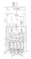
最初に蓄電装置100の構成について説明する。蓄電装置100は、複数の単電池111から構成される組電池110、単電池111の状態を監視する単電池管理手段120、蓄電装置100に流れる電流を検知する電流検知手段130、組電池110の総電圧を検知する電圧検知手段140、及び組電池110の制御を行う組電池制御手段150を備える。組電池制御手段150は、単電池管理手段120から送信される単電池111の電池電圧や温度、電流検知手段130から送信される蓄電装置100に流れる電流値、電圧検知手段140から送信される組電池110の総電圧値が入力されており、入力された情報をもとに組電池110の状態検知などを行う。また、組電池制御手段150が行う処理の結果は、単電池管理手段120や車両制御手段200に送信される。
FIG. 1 shows a configuration example of a power storage device of a plug-in hybrid vehicle in the present embodiment.
First, the configuration of the
車両制御手段200は、組電池制御手段150の情報をもとに、蓄電装置100とリレー300,310を介して接続されるインバータ400及びリレー320,330を介して接続される充電器420の制御を行う。車両走行中には、蓄電装置100はインバータ400と接続され、組電池110が蓄えているエネルギーをもとに、モータジェネレータ410を駆動する。充電の際には、蓄電装置100は充電器420と接続され、家庭用の電源又は電気スタンドからの電力供給で充電される。
The
組電池110は、電気エネルギーの蓄積及び放出(直流電力の充放電)が可能な複数の単電池111(リチウムイオン電池)を電気的に直列に接続して構成される。1つの単電池111は、出力電圧が3.0〜4.2V(平均出力電圧:3.6V)であり、単電池111の開回路電圧(OCV:Open Circuit Voltage)とSOCには図3に示すような相関関係があるとした場合を例に挙げて説明するが、これ以外の電圧仕様のものでも構わない。
The assembled
組電池110を構成する単電池111は、状態の管理・制御を行う上で、所定の単位数にグループ分けが行われている。グループ分けされた単電池111は、電気的に直列に接続され、単電池群112a,112bを構成する。所定の単位数は、例えば1個、4個、6個‥‥というように、等区分とする場合もあれば、4個と6個とを組み合わせる、というように、複合区分とする場合もある。また、高電位側の単電池群112aと低電位側の単電池群112bはスイッチとヒューズが直列接続された保守・点検用のサービスディスコネクタ180を介して、電気的に直列に接続される。
The
組電池110を構成する単電池111の状態を監視する単電池管理手段120は、複数の単電池制御手段121a,121bから構成されており、上記のようにグループ分けされた単電池群112a,112bに対して1つの単電池制御手段121a,121bが割り当てられている。単電池制御手段121a,121bは割り当てられた単電池群112a,112bからの電力を受けて動作し、単電池群112a,112bを構成する単電池111の状態を監視及び制御する。
The unit cell management means 120 for monitoring the state of the
本実施例では、説明を簡単にするために、組電池110は合計8個の単電池111を備え、4個の単電池111を電気的に直列に接続して2つの単電池群112a,112bを構成し、さらに単電池群同士をサービスディスコネクタ180を介して、電気的に直列に接続するものとした。また、単電池群112a,112bには、単電池111の状態を監視するための単電池制御手段121a,121bがそれぞれ設置されている。
In the present embodiment, in order to simplify the description, the assembled
組電池制御手段150は、単電池管理手段120から出力される単電池111の電池電圧や温度の計測値、更には単電池111が過充電若しくは過放電であるかの診断結果や単電池管理手段120に通信エラーなどが発生した場合に出力される異常信号と、電流検知手段130からの電流値と、電圧検出手段140から出力される組電池110の総電圧値と、上位の制御装置である車両制御手段200から出力された信号とを含む複数の信号が入力されている。ここで、入力された情報と、予め記憶されている単電池111の内部抵抗や、SOCとOCVの関係(図3)に基づいて、単電池111のSOC演算や、後に説明する放電終了条件を含んだ電圧均等化制御を行うための演算、充放電量を制御するための演算などを実行する。そして、その演算結果やこれに基づく指令を、単電池管理手段120や車両制御手段200に出力する。
The assembled battery control means 150 includes a measurement value of the battery voltage and temperature of the
組電池制御手段150と単電池管理手段120は、フォトカプラのような絶縁素子170を介して、信号通信手段160により信号の送受信を行う。絶縁素子170を設けるのは、組電池制御手段150と単電池管理手段120とで、動作電源が異なるためである。すなわち、単電池管理手段120は、組電池110から電力をうけて動作するのに対して、組電池制御手段150は、車載補機用のバッテリ(例えば14V系バッテリ)を電源として用いている。絶縁素子170は、単電池管理手段120を構成する回路基板に実装してもよいし、組電池制御手段150を構成する回路基板に実装してもよい。もちろん、単電池管理手段120と組電池制御手段150を1つの回路基板に実装してもよい。なお、システム構成によっては、絶縁素子170を省略することも可能である。
The assembled
本実施例における組電池制御手段150と、単電池制御手段121a,121bとの通信手段について説明する。単電池制御手段121a,121bは、それぞれが監視する単電池群112a,112bの電位の高い順に従って直列に接続されている。組電池制御手段150が送信した信号は、絶縁素子170を介して、信号通信手段160により単電池制御手段121aに入力される。単電池制御手段121aの出力と単電池制御手段121bの入力との間も同様に、信号通信手段160により接続され、信号の伝送を行う。なお、本実施例では、単電池制御手段121aと単電池制御手段121b間は、絶縁素子170を介していないが、絶縁素子170を介していてもよい。そして、単電池制御手段121bの出力は、絶縁素子170を介して、組電池制御手段150の入力を経て、信号通信手段160により伝送される。このように、組電池制御手段150と、単電池制御手段121aと単電池制御手段121bは、信号通信手段160によりループ状に接続されている。このループ接続は、デイジーチェーン接続あるいは数珠繋ぎ接続若しくは芋づる式接続と呼ぶ場合もある。
A communication means between the assembled battery control means 150 and the single battery control means 121a and 121b in this embodiment will be described. The unit
図2に、本実施例における単電池制御手段121a,121bの回路構成を示す。単電池制御手段121a,121bは、バイパス抵抗122とバイパススイッチ123から構成される電圧均等化回路、バイパススイッチ123を駆動するBSW駆動回路125、管理対象とする単電池111の電池電圧を計測する電圧検出回路124、単電池制御手段121a,121bを動作させるための電源126、組電池制御手段150により演算された各単電池111を監視する単電池制御手段121の低消費電力モード(低消費電流モード)への移行条件を記憶する動作モード管理回路127、組電池制御手段150からの情報をもとに単電池制御手段121a,121bの制御を行う制御回路128、組電池制御手段150又は隣り合う単電池制御手段121との間で信号の送受信を行う信号入出力回路129を有する。
In FIG. 2, the circuit structure of the cell control means 121a and 121b in a present Example is shown. The cell control means 121a and 121b are a voltage equalization circuit composed of a
なお、低消費電力モードは、通常モードよりも消費電流が小さい運転モードである。低消費電力モードは、例えば、単電池制御手段121a,121bの複数の機能のうち、一部だけを動作させることで、通常モードと比較して単電池群112a,112bからのエネルギー供給を小さくできる状態になっている。一例として、低消費電力モードは、単電池制御手段121が外部からの通信で通常モードへと移行することが可能な機能のみを動作させている状態であり、少なくとも信号入出力回路129と制御回路128に電力供給を行っている状態である。低消費電力モードに移行した単電池制御手段121は組電池制御手段150からの指令によって通常モードに移行できる。
The low power consumption mode is an operation mode that consumes less current than the normal mode. In the low power consumption mode, for example, by operating only a part of the plurality of functions of the
動作モード管理回路127には、組電池制御手段150により演算された低消費電力モードへの移行条件が記憶される。詳細は後述するが、具体的には、目標となる電圧値や目標値に到達するまでに必要な時間が、動作モード管理回路127に記憶される。
The operation
制御回路128は、組電池制御手段150から送信された電圧取得命令や均等化制御に関する情報を、信号入出力回路129を介して受信し、電圧検出回路124で検出された電池電圧やこれに基づく情報を信号入出力回路129に出力する。蓄電装置が動作を停止する前に、組電池制御手段150から低消費電力モードへの移行条件が入力され、低消費電力モードへの移行条件は、動作モード管理回路127に記憶される。そして、制御回路128は、検出された電池電圧と、動作モード管理回路127に記憶された低消費電力モードへの移行条件をもとにBSW駆動回路125や電源126の制御を行う。
The
本実施例においては、以下に示す放電手段1及び放電手段2の2つの方法を用いて、放電を行うことが可能である。以下に、それぞれの放電手段の詳細を説明する。 In this embodiment, it is possible to perform discharge using the following two methods: discharge means 1 and discharge means 2. Below, the detail of each discharge means is demonstrated.
放電手段1は、蓄電装置の停止時に、放電対象の単電池群112を監視する単電池制御手段121を通常の動作モードに維持することで、単電池群112を目標とする電圧(目標OCV)若しくはSOC(目標SOC)となるまで放電させる。なお、目標OCV若しくは目標SOCとは、例えば、組電池110を構成する複数の単電池111のうち何れかが、過充電となってしまった場合、これを解消するために設定される所定の電圧若しくはSOCであり、詳細は後述する。
The
前述したように、蓄電装置100の停止時に、全ての単電池群112が目標OCV若しくは目標SOCとなるまで単電池制御手段121を通常の動作モードで動作させ、放電手段1による放電が終了した単電池制御手段121から順番に低消費電力モードへ移行させる。なお、本実施例では組電池制御手段150が、放電終了条件1を単電池制御手段121に送信し、動作モード管理回路127へと記憶する構成としているが、他のコントローラから単電池制御手段121に、放電終了条件1を送信する構成としてもよい。
As described above, when the
放電終了条件1について説明する。なお、放電終了条件1を決定するための算出式の説明は、単電池111の個数8個をN個、単電池群112の個数2個をM個、単電池群112を構成する単電池111の個数4個をL個(=N/M)と置き換えて、行うものとする。
The
放電終了条件1の決定方法は、単電池111の電池電圧に基づいて決定する第1の方法と、低消費電力モードへの移行に必要な時間を算出し、その結果に基づいて決定する第2の方法がある。なお、本実施例では、放電終了条件1について上記2つの方法を説明するが、上記2つの方法に限定されるものではない。
The determination method of the
本実施例における放電終了条件1を決定する第1の方法を説明する。
A first method for determining the
単電池群112を構成する複数の単電池111の中で最もOCVの小さい単電池111を、単電池群112ごとに式(1-1)から算出する。
The

式(1-1)により求めたOCVminと目標とするOCV(目標OCV)を比較して、OCVminが目標OCVよりも高い単電池111を有する単電池群112を放電対象として決定する。そして、蓄電装置100の停止時に、対象となった単電池群112を、単電池制御手段121の通常の動作モードの消費電流で放電させる。放電対象となった単電池群112の最小電圧値が、目標OCVと等しくなった時、放電が終了したと判断し、その単電池制御手段121は通常の動作モードから低消費電力モードに移行する。
The OCVmin obtained by the equation (1-1) is compared with the target OCV (target OCV), and the unit cell group 112 having the
本実施例における放電終了条件1を決定する第2の方法を説明する。
放電終了条件1を決定する第2の方法では、所定の放電量を確保するのに必要な時間を算出し、蓄電装置100の停止時に、算出した時間が経過するまでは通常の動作モードで動作させ、算出した時間が経過したら放電が終了として低消費電力モードに移行する。このため、本方法では、算出した時間が経過したかを判断するために、単電池制御手段121にタイマーなどの時間計測手段を設置する。
A second method for determining the
In the second method of determining the
まず、すべての単電池111のOCV測定結果(式(1-1))から、SOCとOCVの相関関係に基づいてSOCを推定し、式(2-1)を用いて単電池群112を構成する単電池111の中で、最もSOCの小さい単電池111のSOC(SOCmin)を単電池群112ごとに検出する。以下、各単電池群112の最小SOCを、SOCmin1,…,SOCminMとする。
First, the SOC is estimated based on the correlation between the SOC and the OCV from the OCV measurement results (Equation (1-1)) of all the
上記、式(2-1)で算出したSOCminと目標とするSOC(目標SOC)との差ΔSOC1を以下の式(2-2)に従って求める。 The difference ΔSOC1 between the SOCmin calculated by the equation (2-1) and the target SOC (target SOC) is obtained according to the following equation (2-2).
求めたΔSOC1より、調整に必要な時間t1を以下の式(2-3)から求める。 From the obtained ΔSOC1, the time t1 required for the adjustment is obtained from the following equation (2-3).
ここで、Qmaxは、単電池111の満充電容量[Ah]を、ICは、単電池制御手段121の消費電流[A]を表す。式(2-3)の結果に基づいて、蓄電装置100の停止時に、単電池制御手段121はt1分だけ通常の動作モードでの動作を維持することで、放電対象の単電池群112を単電池制御手段121の通常動作モードの消費電流で放電させ、時間t1が経過したとき、放電を終了する。つまり、t1分だけ経過した単電池制御手段121から順番に低消費電力モードへ移行させる。
Here, Qmax represents the full charge capacity [Ah] of the
放電手段1によるSOCの変化を、図4を用いて説明する。放電手段1では、各単電池群112の中で最も電圧の小さな単電池111のSOCを抽出し、各単電池群112の最小SOCが一致するまで単電池制御手段121を通常の動作モードで動作させる。単電池群112は単電池111を直列に接続した構成となっているため、単電池群112を構成する全ての単電池111は、単電池制御手段121の消費電流分だけ放電される。そのため、図4のように単電池群112を構成する単電池111のSOCは一様に低下し、各単電池群112の最小SOCが一致したとき、放電手段1を終了する。
The change of the SOC by the discharge means 1 will be described with reference to FIG. In the discharge means 1, the SOC of the
なお、本説明では、組電池110を構成する単電池111の最小電圧値若しくは最小SOCを目標値として、放電終了条件1を決定するものとしたが、これに限られるものではない。
In this description, the
次に、放電手段2について説明する。本実施例における放電手段2は、単電池群112を構成する単電池111の中で、電圧若しくはSOCの高い単電池111を、バイパス抵抗122とバイパススイッチ123から構成される電圧均等化回路を利用して、放電する手段である。つまり、放電の対象となった単電池111に並列に接続されたバイパススイッチ123をオンにし、バイパス抵抗122を用いることで、単電池111を強制的に放電させ、目標となる電圧(目標OCV)若しくはSOC(目標SOC)まで低下させる。ここで、目標OCV若しくは目標SOCとは、前述したように、組電池110を構成する複数の単電池111のうち何れかが、過充電となってしまった場合、これを解消するために設定される所定の電圧若しくはSOCであり、詳細は後述する。なお、本実施例では、放電終了条件2について下記2つの方法を説明するが、下記2つの方法に限定されるものではない。
Next, the discharge means 2 will be described. The discharge means 2 in the present embodiment uses a voltage equalization circuit including a
放電終了条件2を決定する方法は、放電終了条件1と同様に、単電池111の電池電圧に基づいて決定する第1の方法と、単電池111の放電に必要な時間を算出しその結果に基づいて決定する第2の方法がある。
As with the
放電終了条件2を決定する第1の方法について説明する。単電池群112を構成する複数の単電池111の電池電圧を検出し、それぞれの単電池群112ごとに設定された目標OCVと比較して、目標OCVよりも高い電圧を有する単電池111を放電対象の単電池111として決定する。放電の対象となった単電池111に並列に接続されたバイパススイッチ123をオンし、単電池111を強制的に放電させる。放電の対象となった単電池111の電池電圧が、目標OCVと等しくなった時、放電を終了する。
A first method for determining the
放電終了条件2を決定する第2の方法について説明する。放電終了条件2を決定する第2の方法では、放電終了条件1と同様に、所定の放電量を確保するのに必要な時間を算出し、算出した時間が経過したら放電を終了とする。このため、本方法では、単電池制御手段121に、算出した時間が経過したかを判断するために、タイマーなどの時間計測手段を設置する。
A second method for determining the
まず、すべての単電池111のOCV測定結果から、SOCとOCVの相関関係に基づいてSOCを推定し、各単電池111のSOCと目標SOCとの差ΔSOC2を以下の式(2-4)に従って求める。
First, from the OCV measurement results of all the
求めたΔSOC2より、調整に必要な時間t2を以下の式(2-5)から求める。 From the obtained ΔSOC2, the time t2 required for the adjustment is obtained from the following equation (2-5).
ここで、Qmaxは、単電池111の満充電容量[Ah]を、IBは、バイパス抵抗に流れるバイパス電流 [A]を、Xは単電池群を構成する単電池111の番号を表す。式(2-5)の結果に基づいて、放電対象の単電池111を放電させ、所定の放電量を確保するのに必要な時間が経過したとき、放電を終了する。
Here, Qmax is the full charge capacity [Ah] of the
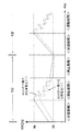
放電手段2によるSOCの変化を図5により説明する。放電手段2では、単電池群112を構成する単電池111の電池電圧が、単電池群112ごとに設定された目標値と、全て一致するように均等化回路を利用してOCVの高い単電池111を放電させる。図示した例の場合、単電池群112aの目標値はA、単電池群112bの目標値はBである。従って、図5のように単電池群112を構成する単電池111の中で放電対象となった単電池111の電池電圧が低下し、単電池群112を構成する全ての単電池111の電池電圧が目標値と一致したとき放電手段2を終了する。
The change of the SOC by the discharge means 2 will be described with reference to FIG. In the discharging
なお、本実施例では、組電池110を構成する単電池111の電圧ばらつきを解消し、電圧の均等化を行うことも可能である。この場合、放電手段1による放電終了の目標値として、組電池110を構成する単電池111の最小電圧値若しくは最小SOC値を設定し、放電手段2による放電の目標値として、単電池制御手段121が管理する単電池111の中の最小電圧値若しくは最小SOC値を、単電池群112ごとに検出して設定すればよい。
In the present embodiment, it is also possible to eliminate the voltage variation of the
続いて、本実施例の蓄電装置における動作の流れを図6のフローチャートに基づいて説明する。 Next, the operation flow in the power storage device of this embodiment will be described based on the flowchart of FIG.
ステップ100では、車両が充電器420からの充電中、又は走行中かを判定する。充電又は走行中の場合はステップ101に進み、充電又は走行中ではない場合は、ステップ104へ進む。
In
ステップ101では、組電池制御手段150が、放電終了条件2を決定し、単電池制御手段121へ、放電終了条件2を送信後、ステップ102へ進む。ステップ101での組電池制御手段150の動作の流れは、図7Aを用いて後に説明する。
In step 101, the assembled
ステップ102では、単電池制御手段121が、放電手段2により放電対象となった単電池111を放電させる。ステップ102での単電池制御手段121の動作の流れは、図8Aを用いて後に説明する。
In step 102, the single
ステップ103では、蓄電装置が、充電の停止信号若しくは車両停止信号を受信したかどうかを判定する。充電の停止信号若しくは車両停止信号を受信した場合は、ステップ104に進む。なお、車両停止信号とは、例えば、車両のキースイッチがオフとなり、車両が停止することを示す信号であり、蓄電装置100の充放電も停止する。また、本説明では、ステップ102で放電を終了していない状態であっても、車両停止信号を受信した場合は、ステップ104に進み、放電手段2による放電を終了とする構成となっているが、ステップ102で終了しなかった処理を車両停止後にも引き続き行う構成とすることも可能である。
In
ステップ104では、組電池制御手段150が単電池制御手段121の消費電流を利用した電圧均等化の放電終了条件1を決定し、単電池制御手段121へ放電終了条件1を送信後、ステップ105へ進む。ステップ104での組電池制御手段150の動作の流れは、図7Bを用いて後に説明する。
In step 104, the assembled battery control means 150 determines the
ステップ105では、単電池制御手段121が、放電終了条件1をもとに電圧均等化を実施する。ステップ105での単電池制御手段121の動作の流れは、図8Bを用いて後に説明する。
In step 105, the
続いて、本実施例における組電池制御手段150の放電終了条件2を決定する動作の流れを、図7Aのフローチャートに基づいて説明する。図7Aは、車両の走行中又は充電中における組電池制御手段150の動作フロー図である。
Subsequently, the flow of the operation for determining the
まず、ステップ110で、全ての単電池111の無負荷時若しくは電流が微弱で無負荷時とみなせる場合の電圧(OCV)を取得する。次にステップ111へ進み、単電池群112を構成する単電池111の電圧又はSOCと、目標とする電圧又はSOCにばらつきがあるかを判定する。ばらつきがあると判定されれば、ステップ112へ進む。
First, in
ステップ112では、バイパス抵抗122とバイパススイッチ123からなる均等化回路を利用した放電手段2の放電終了条件2を決定し、ステップ113で放電終了条件2を単電池制御手段121に送信する。
In step 112, the
続いて、本実施例における組電池制御手段150の放電終了条件1を決定する動作の流れを、図7Bのフローチャートに基づいて説明する。図7Bは、車両停止中における組電池制御手段150の動作フロー図である。
Then, the flow of the operation | movement which determines the
ステップ114では、全ての単電池111のOCVを取得し、ステップ115へ進む。ステップ115では、単電池群112を構成する単電池111の最小電圧若しくはSOCにばらつきがあるかを判定する。電圧若しくはSOCのばらつきがなければ、ステップ117へ進み、単電池制御手段121を低消費電力モードへ移行させ、ステップ119で組電池制御手段150を低消費電力モードへと移行する。ステップ115の判定で単電池111の電圧若しくはSOCにばらつきがあると判定されれば、ステップ116へ進む。
In
ステップ116では、放電終了条件1を決定し、ステップ118で放電終了条件1を単電池制御手段121に送信する。その後、ステップ119で組電池制御手段150を低消費電力モードへ移行する。ここで、組電池制御手段150の低消費電力モードとは、車両起動中の運転モードよりも消費電流が小さい運転モードである。例えば、組電池制御手段150が有する機能のうち、SOCの演算や上述した放電終了条件を演算する機能などを停止し、次回の車両起動時に車両制御手段200から送信される通常モードへの移行命令を受信するための機能を動作させておくことで、通常モードと比較して、車載補機用のバッテリからのエネルギー供給を小さくする運転モードである。
In step 116, the
次に、本実施例における単電池制御手段121の放電手段2の動作の流れを、図8Aのフローチャートに基づいて説明する。図8Aは、車両の走行中若しくは充電中における単電池制御手段121の動作を説明するフローチャートである。 Next, the flow of the operation of the discharge means 2 of the unit cell control means 121 in this embodiment will be described based on the flowchart of FIG. 8A. FIG. 8A is a flowchart for explaining the operation of the unit cell control means 121 while the vehicle is running or charging.
まず、ステップ120で単電池制御手段121は、組電池制御手段150から送信された放電終了条件2を受信する。次に、ステップ121へ進み、バイパス抵抗122とバイパススイッチ123からなる均等化回路を利用して、放電対象となった単電池111からの放電を開始する。
First, in
ステップ122では、単電池群112を構成する全ての単電池の放電が終了したかを判定する。終了したと判定されれば、単電池制御手段121は処理を終了する。ステップ122の判定で全ての単電池111の放電が終了していないと判定された場合は、ステップ123へ進み、放電終了条件2を満たした単電池111があるかを判定する。放電が終了した単電池111があれば、ステップ124に進み、放電が終了した単電池111から順番にバイパススイッチ123をオフにする。その後、ステップ122に戻り、単電池群112を構成する全ての単電池111の放電が終了するまで処理を続ける。
In
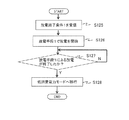
続いて、本実施例における単電池制御手段121の放電手段1による動作の流れを図8Bのフローチャートに基づいて説明する。図8Bは、車両停止中における単電池制御手段121の動作を説明するフローチャートである。 Then, the flow of operation by the discharge means 1 of the unit cell control means 121 in the present embodiment will be described based on the flowchart of FIG. 8B. FIG. 8B is a flowchart for explaining the operation of the unit cell control means 121 while the vehicle is stopped.
まず、ステップ125で単電池制御手段121は、組電池制御手段150から送信された放電終了条件1を受信する。次に、ステップ126へ進み、放電手段1により単電池111の放電を開始する。
First, in
ステップ127では、単電池群112を構成する単電池111の放電が終了したかを判定する。終了したと判定された場合は、単電池制御手段121を低消費電力モードへ移行する。
In
このように、車両の走行中若しくは充電中は、放電手段2によるバイパス抵抗122とバイパススイッチ123から構成される電圧均等化回路を利用した放電で単電池群121を構成する単電池111の電圧又はSOCの均等化を行い、車両停止中は、放電手段1による単電池制御手段121を通常の動作モードに維持することで費やされる消費電流で単電池群間の電圧均等化を行う。なお、蓄電装置100の停止中に、放電手段1に加えて放電手段2による均等化を同時に行ってもよい。
As described above, during traveling or charging of the vehicle, the voltage of the
図9は、単電池制御手段121の管理単位である単電池群112間に、電圧のばらつきが生じている場合のモータジェネレータ410若しくは充電器420による充電動作例を示している。ここでは、単電池群112を構成する単電池111の間にはばらつきはないものとする。図示の場合には、単電池制御手段121aが管理する単電池群112aのみ目標電圧を超えており、単電池制御手段121bが管理する単電池群112bは目標電圧を超えていない。
FIG. 9 shows an example of a charging operation by the
組電池制御手段150は、単電池制御手段毎に目標電圧と単電池群121の電圧とを比較し、目標電圧よりも高い単電池111を有する単電池群121を放電対象として決定する。図9の場合、単電池制御手段121bが管理する単電池群112bは既に目標電圧を下回っているため、単電池制御手段121bの動作モード管理回路127には0が設定されるか、単電池制御手段121bには、低消費電力モードへの移行命令が送信される。一方、単電池制御手段121aが管理する単電池群112aは目標電圧を超えているため、単電池制御手段121aのみ独立して通常モードによる動作を継続し、単電池群112aを放電させる。結果として、組電池制御手段150の動作が停止した後においても、単電池制御手段121aは単電池群112aの電池電圧が目標電圧を超え続けないように、単電池111の管理を行うことができる。
The assembled battery control means 150 compares the target voltage with the voltage of the
なお、本実施例では、組電池110を構成する単電池111の電圧若しくはSOCのばらつきを解消し、電圧の均等化を行うことも可能である。この場合、放電手段1による放電の目標値として、組電池110を構成する単電池111の最小電圧値若しくは所定の放電量を確保するのに必要な時間を設定すればよい。また、放電手段2による放電の目標値に関しても同様に単電池群112を構成する単電池111の中でも最小の電圧若しくはSOCの単電池111に着目し、単電池群112を構成する単電池111の最小電圧値若しくは放電対象の単電池111から所定の放電量を確保するのに必要な時間を設定すればよい。
In this embodiment, the voltage or SOC variation of the
図10及び図11には、単電池群112a若しくは単電池群112bを構成する4個の単電池111の電圧にばらつきが生じており、さらに単電池群112aと単電池群112bの間でも電圧がばらついている場合の電圧均等化の様子を示している。このような場合では、放電手段1と放電手段2の両手法にて、電圧の均等化を行うことで、電圧ばらつきを解消することができる。以下に、電圧ばらつきを解消する方法について説明する。
In FIGS. 10 and 11, the voltages of the four
図10(a)は車両の走行中若しくは充電中に行うバイパス電流による調整の説明図、図10(b)は車両の停止中における消費電流による調整の説明図、図10(c)は調整後の状態を示す図である。まず、単電池群112a及び単電池群112bを構成する単電池111には、図10(a)に示すような電圧若しくはSOCばらつきがあるため、この電圧若しくはSOCばらつきを放電手段2により解消する。ここで、電圧若しくはSOCについての単電池群121aの目標値にはA、単電池群121bの目標値にはB、放電終了後の目標値にはCが設定される。目標値Cは目標値A,Bのうち小さい方、この場合には目標値Bと同じに設定する。
FIG. 10A is an explanatory diagram of adjustment by bypass current while the vehicle is running or charging, FIG. 10B is an explanatory diagram of adjustment by current consumption while the vehicle is stopped, and FIG. It is a figure which shows the state of. First, since the
均等化が終了した単電池111から順番に、単電池111に並列に接続されたバイパススイッチ123をオフにしていき、最終的に単電池群112a,112bを構成する単電池111の電圧若しくはSOCが全て均等になったときに、放電手段2による放電を停止する。各単電池群内でのばらつき解消後の様子を図10(b)に示す。図10(b)では、単電池群112a,112bを構成する単電池111の電圧若しくはSOCばらつきは解消されているので、単電池群112aと単電池群112bの間で生じているSOC若しくは電圧ばらつきを解消すればよい。このSOC若しくは電圧ばらつきは、放電手段1により、単電池群112aを放電させることで解消する。放電終了条件1を満たしたら、単電池制御手段121aは低消費電力モードへ移行する。こうすることで、単電池111の電圧調整終了後には、図10(c)のように全ての単電池111のSOC若しくは電圧ばらつきを解消できる。
The
図11では、図10と同様に、単電池群112a若しくは単電池群112bを構成する4個の単電池111の電圧にばらつきが生じており、さらに単電池群112aと単電池群112bの間でも電圧がばらついている場合のモータジェネレータ410若しくは充電器420による充電動作例を示している。モータジェネレータ410若しくは充電器420による充電制御の以前に測定した単電池111のOCV測定結果に基づいて、放電終了条件2を設定し、充電制御を行っている間は、バイパス抵抗122若しくはバイパススイッチ123を利用した放電を行うことで、単電池制御手段121の管理単位内の単電池111の電圧を均等化する。車両停止信号を受信し、充電制御が終了した後、再度、各単電池のOCVを測定し、その測定結果に基づいて、組電池制御手段150が放電終了条件1を決定する。放電終了条件1を、組電池制御手段150が単電池制御手段121に送信した後、組電池制御手段150は低消費電力モードへ移行する。
In FIG. 11, similarly to FIG. 10, the voltages of the four
図11の例の場合、単電池制御手段121aが監視する単電池群112aを放電対象の単電池群121として決定し、単電池制御手段121aのみ独立して通常モードによる動作を継続して、単電池群112aを放電させる。結果として、組電池制御手段150の動作停止後、単電池制御手段112aへ放電を行うことによって、単電池制御手段121aは単電池群112aの電圧が単電池群112bの電圧と等しくなり、電圧均等化が完了し、車両の停止後においても正確に電圧の均等化を行うことができる。
In the case of the example of FIG. 11, the
なお、組電池110の制御を行う際には、目標となるSOC付近で、単電池111のSOC均等化が行えていることが望ましい。例えば、PHEV若しくはEVでは、高SOCまで充電を行うが、このような状況化では、単電池111の劣化状態が加速する。そのため、高SOC下で、SOCがばらつくと劣化状態にもばらつきが生じ得る。従って、PHEV若しくはEVの場合、高SOC領域で、SOCが均等になっていることが望ましい。図12には、例としてPHEV若しくはEVのSOC変化の様子を示す。図12では、単電池群112aが満充電容量の大きな単電池111から構成されているものとし、単電池群112bが満充電容量の小さな単電池111から構成されているものとした場合に組電池110が充放電を行う様子を表している。一度、高SOC領域で、SOCの均等化を実行し、ばらつきが小さくなっているが、放電を行うと、満充電容量の違いにより、SOCにばらつきが生じる。このSOCばらつきを解消するために、放電終了後に、放電手段1によりSOCの均等化を行った後、充電を行うと、満充電容量の違いにより高SOC領域で、SOCばらつきが発生し得る。
When the
そこで、高SOCでのSOCばらつきを防ぐために、図13に示す目標SOCと目標SOCを上回っている単電池群112とのSOCばらつきから求めた、放電対象となる単電池群112aの放電時間(放電時間1とする)を組電池制御手段150が、EEPROMなどの記録媒体に記憶しておき、放電時間1のみをもとに電圧均等化を行うようにすればよい。そして、組電池制御手段150は、単電池制御手段121aに放電時間1を送信し、低消費電力モードへ移行する。放電対象となった単電池群112aを監視する単電池制御手段121aは、車両の停止中に単電池制御手段121aが監視する単電池群112aが放電を行った時間を計測する(放電時間2とする)。放電対象の単電池群112aの放電が終了せずに車両が動作を開始した場合、単電池制御手段121aは、放電時間2を組電池制御手段150に送信し、組電池制御手段150は、残りの放電量を確保するのに必要な残放電時間を放電時間1から放電時間2を差し引くことで算出して記憶しておく。そして、次の均等化が実行される際に、記憶しておいた残放電時間分だけ放電対象の単電池群112aから放電させる。このようにすれば、図13に示すように高SOC範囲において、SOCを均等にする事ができる。
Therefore, in order to prevent the SOC variation at high SOC, the discharge time (discharge) of the
本発明を適用した場合のSOC均等化に必要な日数をシミュレーションにより見積った。シミュレーション方法を、図14を用いて説明する。シミュレーションは、図1及び図2に示すように、8個の単電池111を2つの単電池群112a,112bに分け、単電池群112a,112bに、単電池制御手段121a,121bを対応させた場合を想定した。図14は、PHEV若しくはEVの1日の運転パターン例を示したものである。まず、家庭用の電源などから、8個の単電池111のうちどれか一つが所定のSOC(上限SOC)になるまで充電を行う。充電終了後に、8個の単電池111のうちどれか一つが、所定のSOC(下限SOC)になるように運転(放電)されるものとし、運転終了後、停止期間に入る。今回のシミュレーションでは、車両の運転期間を1日あたり2時間とし、残りの22時間を停止期間とした。これを1日のサイクルとし、毎日同じサイクルを繰り返すものとした。
The number of days required for SOC equalization when the present invention was applied was estimated by simulation. The simulation method will be described with reference to FIG. In the simulation, as shown in FIGS. 1 and 2, the eight
単電池111の容量は20Ahを想定し、バイパス抵抗122に流れる電流は20mA、単電池制御手段121の動作に必要な消費電流は3mAとした。単電池111のSOCはすべてばらついているものとして、8個の単電池111のうち、4個のSOCの高い単電池111が単電池群112aを構成するものとし、残り4個のSOCの小さな単電池111が単電池群112bを構成するものとした。電圧均等化を行う前の一番SOCの高い単電池111と、一番SOCの小さな単電池111のSOCの差は5%であるとし、このSOCばらつき5%を解消するのに必要な日数を見積もった。
The capacity of the
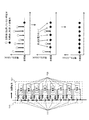
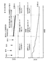
図15(a)(b)は、車両の走行中のみ電圧均等化を行った場合のSOCの均等化の様子を示す。また、図16(a)(b)は、車両の走行中のみでなく、停止中にも放電対象の単電池を監視する単電池制御手段を動作させておくことで単電池群から放電し、電圧均等化を行った場合のSOCの均等化の様子を示す。 FIGS. 15A and 15B show the state of SOC equalization when voltage equalization is performed only while the vehicle is running. 16 (a) and 16 (b) are discharged from the unit cell group by operating the unit cell control means for monitoring the unit cell to be discharged not only during traveling of the vehicle but also during stoppage. The state of SOC equalization when voltage equalization is performed is shown.
図15(a)及び図16(a)は、組電池110の充電終了後における各単電池111のSOCの様子を表している。組電池110を構成する単電池111の中でSOCが最も高い単電池111が最初に充電の目標とする上限SOCに到達し、充電を終了する。そのため、SOCが最も高い単電池111以外の単電池111は、充電が終了しても充電の目標とするSOCに到達しないが、電圧均等化を開始すると、日数が経過するにつれて、SOCのばらつきが解消されていき、SOCが最も大きい単電池111以外の単電池111も充電の目標とする上限SOCに近づいていく。
FIG. 15A and FIG. 16A show the state of the SOC of each
図15(b)及び図16(b)は、組電池110の放電終了後、停止期間を経て、充電を開始する直前の各単電池111のSOCを表している。放電終了時は、充電終了時とは反対に、SOCが最も小さい単電池111が下限SOCの値に到達したら、放電を終了する。従って、充電終了時に、組電池110を構成する複数の単電池111の中で、SOCが最も小さい単電池111が最初に、放電の下限SOCに到達し、SOCが最も小さい単電池111以外の単電池111は、放電の下限SOCに到達する前に放電を終了してしまうが、電圧均等化を開始すると、日数が経過するにつれて、SOCのばらつきが解消されていき、SOCが最も小さい単電池111以外の単電池111も目標とする放電の下限SOCに近づいていく。
FIG. 15B and FIG. 16B show the SOC of each
上述したように電圧均等化が進むと、組電池110を構成する全ての単電池111のSOCが、充電の目標値となる上限SOCへ、若しくは放電の下限SOCへ近づくため、充放電期間中のSOC稼働範囲が広くなっていくことが分かる。
As described above, when the voltage equalization proceeds, the SOC of all the
図15及び図16から上述した電圧均等化が終了するのに必要な時間を見積もると、車両の走行中のみ電圧均等化を行った場合(図15)は、電圧均等化に必要な日数が25日であるのに対して、走行中だけでなく停止期間中にも電圧の均等化を行う場合(図16)に必要な日数は14日と、走行中のみ電圧均等化を行う場合と比較して、約10日間、電圧均等化に必要な日数を短くすることができる。 When the time required for completing the voltage equalization described above is estimated from FIGS. 15 and 16, when voltage equalization is performed only while the vehicle is traveling (FIG. 15), the number of days required for voltage equalization is 25. Compared to the case where voltage equalization is performed only during traveling, the number of days required for voltage equalization not only during traveling but also during a stop period (FIG. 16) is 14 days. Thus, the number of days required for voltage equalization can be shortened for about 10 days.
なお、本実施例では、車両停止中は、放電手段1による電圧均等化のみを行う方法を主に説明したが、車両停止中に、単電池群を構成する単電池に電圧若しくはSOCのばらつきがある場合は、車両停止中にも、放電手段2による放電を実施するようにしてもよい。
In the present embodiment, the method of performing only the voltage equalization by the discharging
本実施例によれば、単電池制御手段121の低消費電力モードへの移行条件を設定するだけで、単電池の電池電圧若しくはSOCを管理することが可能となるので、簡単な処理、少ない命令数で、組電池110を制御可能な蓄電器制御回路若しくは蓄電装置を実現できる。
According to the present embodiment, it is possible to manage the battery voltage or SOC of the unit cell simply by setting the condition for shifting to the low power consumption mode of the unit cell control means 121. It is possible to realize a battery control circuit or a power storage device that can control the assembled
[実施例2]
本発明の第2実施例について、図17及び図18に基づいて説明する。
図17に、本実施例におけるプラグインハイブリッド自動車の蓄電装置100の構成例を示す。本実施例では、2個の単電池111を電気的に並列に接続して並列単電池113とし、それを電気的に直列に8組接続し、組電池110が構成されているものとした。また、本実施例では並列単電池113を4個直列に接続して単電池群112a,112bが構成されている。
[Example 2]
A second embodiment of the present invention will be described with reference to FIGS.
FIG. 17 shows a configuration example of the
上記のようにグループ分けされた単電池群112a,112bに対して単電池制御手段121a,121bが割り当てられる。単電池制御手段121a,121bは、単電池群112a,112bに対して並列に接続され、割り当てられた単電池群112a,112bを構成する並列単電池113の状態を監視・制御する。
The
上記のように、本実施例は、組電池110の構成のみが実施例1とは異なっており、その他の電流検知手段130や組電池制御手段150といった構成に関しては、実施例1と同様である。
As described above, the present embodiment is different from the first embodiment only in the configuration of the assembled
図18に、本実施例における単電池制御手段121の回路構成図を示す。本実施例では、実施例1と比較して、単電池111が2個並列に接続された並列単電池113を、直列に接続した構成となっている点のみが異なっている。また、バイパス抵抗122及びバイパススイッチ123から構成される均等化回路が、1組の並列単電池113に対して並列に接続されており、BSW駆動回路125により、バイパススイッチ123を駆動することが可能な構成となっている。
In FIG. 18, the circuit block diagram of the cell control means 121 in a present Example is shown. The present embodiment is different from the first embodiment only in that the parallel
本実施例における放電終了条件の決定方法を説明する。本実施例では、単電池111が並列に2個接続された構成となっていることから、放電終了条件1及び放電終了条件2を決定する第2の方法、つまり、所定の放電量を確保するのに必要な時間を演算する方法のみが、実施例1とは異なる。放電終了条件1及び放電終了条件2を決定する第1の方法、つまり、並列単電池113の電池電圧に基づいて放電終了条件を決定する方法は、実施例1に記載の方法と同様である。そこで、本実施例における所定の放電量を確保するのに必要な時間の算出方法について説明する。
A method for determining the discharge end condition in the present embodiment will be described. In this embodiment, since the
本実施例における放電終了条件1を決定する第2の方法について説明する。まず、組電池を構成する並列単電池113のOCVを測定し、SOCとOCVの相関関係に基づいてSOCを推定する。そして、単電池群112a,112bを構成する並列単電池113の中で、最もSOCの小さい並列単電池113のSOC(SOCmin)を式(2-1)に従って算出する。以下、各単電池群112a,112b,…を構成する単電池111の最小SOCを、SOCmin1,…,SOCminMとする。
A second method for determining the
上記、式(2-1)の算出結果に基づいて放電終了条件1を決定するために、各単電池群112のSOCminと目標とするSOC(目標SOC)との差ΔSOC1を式(2-2)に従って求める。
In order to determine the
求めたΔSOC1より、調整に必要な時間t1′を以下の式(2-3′)から求める。 From the obtained ΔSOC1, time t1 ′ required for adjustment is obtained from the following equation (2-3 ′).
ここで、Qmaxは、単電池111の満充電容量[Ah]である。ICは、単電池制御手段121の消費電流[A]を表す。所定の放電量を確保するのに必要な時間は、並列に接続した単電池111の個数分を乗算して求める必要がある。そのため、式(2-3′)のように、並列に接続された単電池111の個数(本実施例では2)分を乗算している。上記算出結果に基づいて、放電対象の単電池群112を放電させ、所定の放電量を確保するのに必要な時間が経過したとき、放電を終了する。
Here, Qmax is the full charge capacity [Ah] of the
同様に、本実施例における放電終了条件2を決定する第2の方法について、説明する。
式(2-1)により算出された結果に基づいて、単電池群112のSOCminと並列単電池113のSOCとの差ΔSOC2を式(2-4)に従って求める。
Similarly, a second method for determining the
Based on the result calculated by the equation (2-1), a difference ΔSOC2 between the SOCmin of the unit cell group 112 and the SOC of the
求めたΔSOC2より、調整に必要な時間t2′を以下の式(2-5′)から求める。 From the obtained ΔSOC2, time t2 ′ required for adjustment is obtained from the following equation (2-5 ′).
ここで、IBは、並列単電池113に並列に接続された均等化回路を流れるバイパス電流[A]を表す。ここでも、式(2-5′)と同様に並列単電池113を構成する単電池111の個数(本実施例では2個)分を乗算している。式(2-5′)の結果に基づいて、放電対象の並列単電池113を放電させ、放電に必要な時間が経過したとき、放電を終了とする。
Here, I B represents the bypass current [A] through the equalizing circuit connected in parallel to the
本実施例における蓄電装置の動作の流れについては、実施例1における蓄電装置の動作(図6)と同様である。 The operation flow of the power storage device in the present embodiment is the same as the operation of the power storage device in the first embodiment (FIG. 6).
本実施例における組電池制御手段150の動作に関しては、実施例1における組電池制御手段150の動作(図7A、図7B)と同様である。 The operation of the assembled battery control means 150 in the present embodiment is the same as the operation of the assembled battery control means 150 in the first embodiment (FIGS. 7A and 7B).
本実施例における単電池制御手段121の動作に関しては、実施例1における単電池制御手段121の動作(図8A、図8B)と同様である。
The operation of the unit
本実施例によれば、並列単電池113を構成する2つの単電池111の電圧は等しいため、放電手段1と放電手段2により放電対象となった並列単電池113を放電させることで、実施例1と同様の効果が期待できる。
According to the present embodiment, since the voltages of the two
[実施例3]
本発明の第3実施例について図19から図27に基づいて説明する。なお、本実施例では、1個の単電池111に対して、1個の単電池制御手段121を対応させた構成となっており、1個の単電池111の状態を1個の単電池制御手段121が監視する。この点が実施例1とは異なっている。
[Example 3]
A third embodiment of the present invention will be described with reference to FIGS. In this embodiment, one
本実施例におけるプラグインハイブリッド自動車の駆動系を含めた蓄電装置100の構成例を図19に示す。本実施例では、説明を簡単にするために実施例1と同様に8個の単電池111が組電池110を構成するものとした。
FIG. 19 shows a configuration example of the
また、本実施例における単電池制御手段121の回路構成を図20に示す。1個の単電池に対して、1個の単電池制御手段121を対応させる場合、単電池制御手段121の動作に必要な消費電流を利用した放電手段1のみで単電池111間の電圧の調整が可能となる。従って、バイパス抵抗122とバイパススイッチ123からなる均等化回路を利用した放電手段2による放電手段2を使う必要がない。よって、第1実施例における単電池制御手段121の回路構成と比べて、バイパス抵抗122とバイパススイッチ123及びバイパススイッチ123を駆動するBSW駆動回路125が必要ないので、単電池制御手段121の回路構成を、簡素な構成とすることが可能となる。
Further, FIG. 20 shows a circuit configuration of the unit cell control means 121 in the present embodiment. When one unit
本実施例における放電終了条件1の決定方法について説明する。なお、放電終了条件1を決定するために適用する算出式の説明は、単電池111の個数8個をN個と置き換えて、行うものとする。
A method for determining the
本実施例における放電終了条件1を決定する第1の方法について説明する。組電池110を構成する単電池111のOCVをそれぞれ検出し、目標とするOCV(目標OCV)と検出した単電池111のOCVとを比較する。その結果、目標OCVよりも高いOCVの単電池を放電対象の単電池として決定し、対象となった単電池111を、車両停止時に単電池制御手段121の通常モードの消費電流で放電させる。放電対象となった単電池111の電圧値が、目標OCVと等しくなった時、放電を終了し、放電を終了した単電池111を監視する単電池制御手段121を低消費電力モードへ移行する。
A first method for determining the
本実施例における放電終了条件1を決定する第2の方法を説明する。放電終了条件1を決定する第2の方法では、所定の放電量を確保するのにかかる時間を算出し、車両停止時に対象となった単電池111を単電池制御手段121の通常モードの消費電流で放電させる。そして、算出した時間が経過したら放電を終了とし、放電を終了した単電池を監視する単電池制御手段を低消費電力モードへ移行する。このため、本方法では、単電池制御手段121に、算出した時間を計測するためのタイマーなどの時間計測手段を設置するものとする。
A second method for determining the
まず、組電池110を構成する単電池111のOCV測定結果から、SOCとOCVの相関関係に基づいてSOCを推定し、各単電池111のSOCと目標とするSOC(目標SOC)との差ΔSOC3を以下の式(3-1)に従って求める。
First, the SOC is estimated based on the correlation between the SOC and the OCV from the OCV measurement result of the
求めたΔSOC3より、調整に必要な時間t3を以下の式(3-2)から求める。 From the obtained ΔSOC3, the time t3 required for the adjustment is obtained from the following equation (3-2).
ここで、Qmaxは、単電池111の満充電容量[Ah]を、ICは、単電池制御手段121の消費電流[A]を表す。式(3-2)の結果に基づいて、車両停止時に、放電対象の単電池111を放電させ、所定の放電量を確保するのに必要な時間が経過したとき、放電を終了する。
Here, Qmax represents the full charge capacity [Ah] of the
なお、本実施例では、実施例1と同様に組電池110を構成する単電池111の電圧ばらつきを解消し、電圧の均等化を行うことも可能である。この場合、放電手段1による放電の目標値として、組電池110を構成する単電池111の最小電圧値若しくは最小SOC値を設定すればよい。
In the present embodiment, as in the first embodiment, it is possible to eliminate the voltage variation of the
続いて、本実施例における蓄電装置の動作の流れを図21のフローチャートに基づいて、説明する。 Next, the operation flow of the power storage device in the present embodiment will be described based on the flowchart of FIG.
まず、ステップ300で蓄電装置が、充電の停止信号若しくは車両停止信号を受信したかどうかを判定する。充電の停止信号若しくは車両停止信号を受信した場合は、ステップ301へ進む。
First, in
ステップ301では、組電池制御手段150が単電池制御手段121の消費電流を利用した電圧均等化の放電終了条件1を決定し、単電池制御手段121へ放電終了条件1を送信する。ステップ301での組電池制御手段150の動作の流れは、図22を参照して後に説明する。
In step 301, the assembled
次に、ステップ302では、放電終了条件1をもとに、単電池制御手段121が監視する単電池111の放電を実施する。ステップ302での単電池制御手段121の動作の流れは、図23を参照して後に説明する。
Next, in step 302, based on
本実施例における組電池制御手段150の動作の流れを、図22のフローチャートに基づいて説明する。 The operation flow of the assembled battery control means 150 in the present embodiment will be described based on the flowchart of FIG.
まず、ステップ310で組電池110を構成する単電池111のOCVを取得する。その後、ステップ311に進み、取得したOCVの値と目標OCVの値を比較して、電圧又はSOCのばらつきがあるかを判定する。ステップ311で電圧又はSOCのばらつきがないと判定された場合は、ステップ314に進み、単電池制御手段112を低消費電力モードへ移行する。
First, in
ステップ311で電圧又はSOCのばらつきがあると判定された場合は、ステップ312に進み、単電池制御手段121の消費電流を利用した放電手段1の放電終了条件1を決定し、ステップ313で放電終了条件を単電池制御手段121に送信する。その後、ステップ315で組電池制御手段150を低消費電力モードへ移行する。
If it is determined in step 311 that there is a variation in voltage or SOC, the process proceeds to step 312 to determine the
続いて、本実施例における単電池制御手段121の動作の流れを図23のフローチャートに基づいて説明する。 Next, the flow of the operation of the unit cell control means 121 in this embodiment will be described based on the flowchart of FIG.
まず、ステップ320で単電池制御手段121は、組電池制御手段150から送信された放電終了条件1を受信する。次に、ステップ321へ進み、単電池制御手段121の消費電流を利用した放電を開始する。ステップ322では、組電池110を構成する単電池111の放電が終了したかを判定する。終了したと判定された場合は、ステップ323に進み、単電池制御手段121を低消費電力モードへ移行する。
First, in
図24は、単電池制御手段121が監視する単電池111間に、電圧のばらつきが生じている場合のモータジェネレータ410若しくは充電器420による充電動作例を示している。
FIG. 24 shows an example of a charging operation by the
組電池制御手段150は、充放電停止中に、単電池制御手段121が監視する単電池111の電圧と目標電圧とを比較し、目標電圧よりも高い単電池111を放電対象として決定する。ここで、既に目標電圧よりも電圧が下回っている単電池111を監視する単電池制御手段121の動作モード管理回路127には0が設定されるか、単電池制御手段121には、低消費電力モードへの移行命令が送信される。一方、目標電圧よりも高い電圧を有する単電池111を監視する単電池制御手段121は、その単電池制御手段121のみ独立して通常モードによる動作を継続し、放電対象となった単電池111を放電させる。そして、放電が終了した単電池111を監視する単電池制御手段121から順番に低消費電力モードへ移行する。結果として、組電池制御手段150の動作が停止した後においても、単電池制御手段121は、単電池111の電池電圧が目標電圧を超え続けないように、単電池111の管理を行うことができる。
The assembled
図25及び図26は、組電池110を構成する8個の単電池111の電圧にばらつきが生じている場合の電圧均等化の様子を示している。本実施例では、実施例1とは異なり、放電手段1のみで電圧の均等化を行うことが可能である。以下に、電圧若しくはSOCのばらつきを解消する方法について説明する。
25 and 26 show the state of voltage equalization when the voltages of the eight
図25に、本実施例における電圧均等化の様子を示す。蓄電装置停止後の8個の単電池111のSOCは、図25の右上図に示すようにすべてばらついている。
FIG. 25 shows a state of voltage equalization in the present embodiment. The SOCs of the eight
ここで、蓄電装置停止時に、式(3-2)で求めた所定の放電量を確保するのに必要な時間といった放電終了条件に基づいて、調整対象の単電池111を監視する単電池制御手段121を通常モードで動作させ、電圧均等化を行う。そして、図25の右中段の図に示すように、調整が終了した単電池制御手段121から順番に低消費電力モードへ移行する。こうすることで、調整終了後には、図25の右下図のように全ての単電池111の電圧を均等化できる。
Here, when the power storage device is stopped, the unit cell control means for monitoring the
図26は、単電池制御手段121が監視する単電池111間に、電圧のばらつきが生じている場合のモータジェネレータ410若しくは充電器420による充電動作例を示している。車両停止信号を受信後に、組電池制御手段150は、組電池110を構成する単電池111の電池電圧から最小電圧値を抽出し、目標電圧値として設定する。単電池制御手段121が監視する単電池111の電圧と目標電圧値とを比較し、目標電圧よりも高い単電池111を放電対象として決定する。ここで、既に目標電圧よりも電圧が下回っている単電池111を監視する単電池制御手段121の動作モード管理回路127には0が設定されるか、単電池制御手段121には、低消費電力モードへの移行命令が送信される。一方、目標電圧よりも高い電圧を有する単電池111を監視する単電池制御手段121は、その単電池制御手段121のみ独立して通常モードによる動作を継続し、放電対象となった単電池111を放電させ、放電が終了した単電池111を監視する単電池制御手段から順番に低消費電力モードへ移行させる。結果として、組電池制御手段150の動作が停止した後においても、単電池制御手段121は単電池111の電池電圧が目標電圧を超え続けないように、単電池111の管理を行うことができる。
FIG. 26 shows an example of the charging operation by the
以上説明した方法で電圧の均等化を行えば、車両の蓄電装置停止後においても正確に電圧の均等化を行うことができる。また、組電池110が満充電容量の異なる単電池111から構成されている場合も、実施例1で述べたような方法で放電終了条件1を設定すれば、目標とするSOCの範囲内で電圧の均等化を行うことが可能である。
If the voltage is equalized by the method described above, the voltage can be accurately equalized even after the power storage device of the vehicle is stopped. Further, even when the assembled
図27(a)(b)は、実施例1で図14により説明した方法と同様のサイクルで、SOCの均等化に必要な日数を見積った結果を示している。今回のシミュレーションでは、1個の単電池111に対して、1個の単電池制御手段121が割り当てられており、バイパススイッチ122とバイパス抵抗123から構成される放電回路がないものとした。つまり、電圧均等化は車両の停止期間中にのみ行われる。図27(a)は充電終了後の各単電池111のSOCの変化を示し、図27(b)は充電開始直前の各単電池のSOCの変化を示している。図の縦軸はSOC(%)であり、横軸は日数である。
FIGS. 27A and 27B show the result of estimating the number of days required for SOC equalization in the same cycle as the method described in FIG. 14 in the first embodiment. In this simulation, it is assumed that one single
本実施例においても実施例1の図15及び図16と同様に、充電終了後は組電池110を構成する全ての単電池111が充電の目標とする上限SOCに近づいていき、充電開始直前では、組電池110を構成する全ての単電池111が放電の下限SOCに近づいていることが分かる。図より、SOCの均等化に必要な日数は18日となり、車両の走行中のみ電圧均等化を行った場合の24日(図15)と比較して、SOCの均等化に必要な日数を減らすことができる。
Also in the present embodiment, as in FIG. 15 and FIG. 16 of the first embodiment, after the end of charging, all the
本実施例によれば、単電池制御手段121の低消費電力モードへの移行条件を設定するだけで、単電池111の電池電圧若しくはSOCを管理することが可能となるので、簡単な処理、少ない命令数で、組電池110を制御可能な蓄電器制御回路若しくは蓄電装置を実現できる。
According to the present embodiment, it is possible to manage the battery voltage or SOC of the
[実施例4]
本発明の第4実施例について、図28及び図29に基づいて説明する。図28は、本実施例におけるプラグインハイブリッド自動車の駆動系を含めた蓄電装置の構成例を示す図である。図29は、単電池制御手段121の回路構成図である。
[Example 4]
A fourth embodiment of the present invention will be described with reference to FIGS. FIG. 28 is a diagram illustrating a configuration example of the power storage device including the drive system of the plug-in hybrid vehicle in the present embodiment. FIG. 29 is a circuit configuration diagram of the unit cell control means 121.
本実施例では2個の単電池111を電気的に並列に接続した並列単電池113を電気的に直列に8組接続し、組電池110が構成されており、実施例3と比較して、この点のみが異なっている。
In this embodiment, eight sets of
本実施例における放電終了条件の決定方法について説明する。本実施例では、実施例3と同様に放電手段1のみにより単電池111からの放電を行う。
A method for determining the discharge end condition in this embodiment will be described. In the present embodiment, the discharge from the
本実施例における放電終了条件1の決定方法について説明する。なお、放電終了条件1を決定するために適用する算出式の説明は、並列単電池113の個数8個をN個と置き換えて、行うものとする。
A method for determining the
本実施例における放電終了条件1を決定する第1の方法は、実施例3と同様である。
本実施例における放電終了条件1を決定する第2の方法を説明する。まず、組電池110を構成する並列単電池113のOCV測定結果から、SOCとOCVの相関関係に基づいてSOCを推定し、上記検出結果と組電池110を構成する並列単電池113のSOCと目標とするSOC(目標SOC)との差ΔSOC3を式(3-1)に従って求める。求めたΔSOC3より、調整に必要な時間t3′を以下の式(3-2′)から求める。
The first method for determining the
A second method for determining the
ここで、Qmaxは、単電池111の満充電容量[Ah]を、ICは、単電池制御手段121の消費電流[A]を表す。実施例2と同様に、並列単電池113を構成する単電池111の個数(本実施例では2個)分を乗算している。式(3-2′)の結果に基づいて、放電対象の並列単電池113を放電させ、所定の放電量を確保するのに必要な時間が経過したとき、放電を終了とする。
Here, Qmax represents the full charge capacity [Ah] of the
本実施例における蓄電装置の動作に関しては、実施例3における蓄電装置の動作(図21)と同様である。 The operation of the power storage device in the present embodiment is the same as the operation of the power storage device in the third embodiment (FIG. 21).
本実施例における組電池制御手段150の動作に関しては、実施例3における組電池制御手段150の動作(図22)と同様である。 The operation of the assembled battery control means 150 in this embodiment is the same as the operation of the assembled battery control means 150 in Embodiment 3 (FIG. 22).
本実施例における単電池制御手段121の動作に関しては、実施例3における単電池制御手段121の動作(図23)と同様である。 The operation of the cell control means 121 in this embodiment is the same as the operation of the cell control means 121 in Embodiment 3 (FIG. 23).
本発明によれば、並列単電池113を構成する2つの単電池111は、無負荷時においてSOCが等しくなるので、実施例3と同様の効果が期待できる。
According to the present invention, since the two
[実施例5]
本発明の第5実施例を図30に基づいて説明する。本実施例は、単電池111から電力を受けて動作すると共に、単電池111の状態を監視する単電池制御手段121を備えた蓄電装置100に対して適用可能である。
[Example 5]
A fifth embodiment of the present invention will be described with reference to FIG. The present embodiment can be applied to the
本実施例は、組電池制御手段150と単電池制御手段121との間で通信エラーが発生し、正確に放電終了条件を受信できなかった場合、単電池制御手段121を自動的に低消費電力モードへ移行させる機能を備えるものとした。本実施例における組電池制御手段150の動作は、図7若しくは図22と同様である。 In this embodiment, when a communication error occurs between the assembled battery control means 150 and the single battery control means 121 and the discharge end condition cannot be correctly received, the single battery control means 121 is automatically turned to low power consumption. A function to shift to the mode is provided. The operation of the assembled battery control means 150 in this embodiment is the same as that in FIG. 7 or FIG.
本実施例における単電池制御手段121の動作を図30に基づいて説明する。尚、図30における単電池制御手段121のフローチャートは、蓄電装置100が車両停止信号を受信し、組電池制御手段150により放電終了条件が演算されたあとの単電池制御手段121の動作を説明するものとする。
まず、ステップ500で組電池制御手段150から放電終了条件を受信したかどうかを判定する。
The operation of the cell control means 121 in this embodiment will be described with reference to FIG. Note that the flowchart of the unit
First, in step 500, it is determined whether or not a discharge end condition has been received from the assembled battery control means 150.
正確に放電終了条件を受信した場合は、ステップ501に進み、放電手段1により、電圧均等化を実施する。その後、電圧均等化が終了したら、ステップ502に進み単電池制御手段121を低消費電力モードへ移行させる。 When the discharge end condition is correctly received, the process proceeds to step 501 where the discharge means 1 performs voltage equalization. Thereafter, when the voltage equalization is completed, the process proceeds to step 502, and the unit cell control means 121 is shifted to the low power consumption mode.
ステップ500で放電終了条件を受信できなかった場合、ステップ503に進む。ステップ503では、車両の停止後、所定の時間経過したかを判定する。ステップ503で所定の時間経過していない場合は、ステップ500に戻り、放電終了条件1を受信したかを再度判定する。
If the discharge end condition cannot be received in step 500, the process proceeds to step 503. In step 503, it is determined whether a predetermined time has elapsed since the vehicle stopped. If it is determined in step 503 that the predetermined time has not elapsed, the process returns to step 500 to determine again whether or not the
ステップ503で所定の時間が経過した場合は、組電池制御手段150と単電池制御手段121との間に通信エラーが発生し、単電池制御手段121が放電終了条件を正確に受信できなかったと判定して、ステップ502に進み、単電池制御手段121を低消費電力モードへ移行する。 If the predetermined time has elapsed in step 503, it is determined that a communication error has occurred between the assembled battery control means 150 and the single battery control means 121, and the single battery control means 121 has not been able to correctly receive the discharge end condition. Then, the process proceeds to step 502, and the unit cell control means 121 is shifted to the low power consumption mode.
本実施例によれば、組電池制御手段150と単電池制御手段121との間に通信エラーが発生した場合でも、単電池制御手段121が動作したままの状態になることを防止し、単電池111が過放電状態になることを防ぐことができる。 According to this embodiment, even when a communication error occurs between the assembled battery control means 150 and the single battery control means 121, the single battery control means 121 is prevented from remaining in an operating state, and the single battery is It can prevent that 111 becomes an overdischarge state.
[実施例6]
本発明の第6実施例について説明する。
本実施例では、単電池制御手段121の動作に必要な消費電流の個体差によるばらつきに着目する。単電池制御手段121はものによっては、消費電流が小さいものも、大きいものも存在する。単電池制御手段121は図2のように単電池群112若しくは図20のように単電池111からのエネルギー供給で動作を行うため、単電池制御手段121の消費電流の個体差が大きい場合には、その個体差によって単電池群112若しくは単電池111の電圧若しくはSOCばらつきが発生してしまう。
[Example 6]
A sixth embodiment of the present invention will be described.
In the present embodiment, attention is paid to variations due to individual differences in current consumption necessary for the operation of the cell control means 121. Depending on the unit cell control means 121, there are a small current consumption and a large one. Since the unit cell control means 121 operates by supplying energy from the unit cell group 112 as shown in FIG. 2 or the
そこで、単電池制御手段121の消費電流ばらつきを、単電池制御手段121の製造時に予め測定しておき、測定結果を組電池制御手段150に記憶させておく。組電池制御手段150は、予め記憶しておいた消費電流の値を利用して、式(2-3)、式(2-5)、式(2-3′)、式(2-5′)、式(3-2)、式(3-2′)の消費電流値ICをそれぞれの単電池制御手段121の消費電流値に置き換えて、所定の放電量を確保するのに必要な時間を算出する。そして、組電池制御手段150は単電池制御手段121に、所定の放電量を確保するのに必要な時間を送信する。その後、組電池制御手段150は低消費電力モードへ移行し、単電池制御手段121は、組電池制御手段150が算出した時間だけ通常モードで動作した後で低消費電力モードに移行する。このようにすれば、単電池制御手段121の個体差による消費電流のばらつきが電圧若しくはSOCばらつきに与える影響を抑えたSOC管理を行うことが可能となる。
Therefore, the current consumption variation of the
なお、上述した説明では、消費電流のばらつきに関する情報を組電池制御手段150に記憶させる構成としたが、単電池制御手段121が個々の消費電流値を記憶しておくようにしてもよい。このような場合、車両停止信号を受信した後に、単電池制御手段121に記憶されている消費電流の値を、単電池111の情報と共に組電池制御手段150に送信すればよい。単電池制御手段121の情報を受信した組電池制御手段150は、式(2-3)、式(2-5)、式(2-3′)、式(2-5′)、式(3-2)、式(3-2′)中の消費電流値ICをそれぞれの単電池制御手段121の消費電流値に置き換えて、所定の放電量を確保するのに必要な時間を算出する。組電池制御手段150は、単電池制御手段121に所定の放電量を確保するのに必要な時間を送信し、低消費電力モードへ移行する。そして、単電池制御手段121を、組電池制御手段150が算出した時間だけ通常モードで動作させて単電池111の放電を行うことにより、単電池制御手段121の個体差による消費電流のばらつきがSOCばらつきに与える影響を抑えたSOC管理を行うことが可能となる。
In the above description, the battery
本実施例は、単電池111から電力を受けて動作すると共に、単電池111の状態を監視する単電池制御手段121を備えた蓄電装置に対して適用可能である。
The present embodiment is applicable to a power storage device that operates by receiving electric power from the
[実施例7]
本発明の第7実施例について、図31から図33に基づいて説明する。
本実施例の蓄電装置100は、SOCのばらつきが大きい単電池111を監視する単電池制御手段121の消費電力が大きくなるように動作を変更させ、電圧若しくはSOCばらつきの解消を促進させる機能を有する。
[Example 7]
A seventh embodiment of the present invention will be described with reference to FIGS.
The
図31に、本実施例における単電池制御手段121の回路構成を示す。本実施例においては、図20に示す単電池制御手段121の回路に、消費電力変更回路128′を加え、更に、一つの単電池111に対して一つの単電池制御手段121を備える構成を例に説明する。また、ここでの電圧検出回路124は、組電池制御手段150からの指令に基づき単電池111の電圧の取得を開始するものとする。
FIG. 31 shows a circuit configuration of the unit cell control means 121 in the present embodiment. In the present embodiment, a configuration in which a power
図31に示した消費電力変更回路128′は、単電池制御手段121が、組電池制御手段150からの放電終了条件を受信し、信号内の時間情報を動作モード管理回路127に設定し、単電池制御手段121が設定された時間を経過するまで通常モードによる動作を継続する間、電圧検出回路124のサンプリング速度を変更する。
In the power
図32を用いて、本実施例における電圧検出回路124の動作を説明する。本実施例では、動作モード管理回路127に時間情報を設定し、設定時間を経過するまでの単電池制御手段121の通常モードでの動作継続中は、組電池制御手段150からの指令がない状態でも電圧検出回路124が単電池111の電圧を連続的に検出するモードに移行する。そして、動作モード管理回路127に設定した時間を経過した場合、単電池制御手段121は低消費電力モードに移行し、これと共に電圧検出回路124の動作も停止する。
The operation of the
前述した消費電力変更回路128′に基づいた電圧検出回路124の動作変更により、単電池制御手段121の消費電流を増加させるように変更できるため、単電池制御手段121の管理対象である単電池111のエネルギー消費を通常に比して大きくできる。結果として、単電池111のSOC若しくは電圧を比較的短時間で低下させることが可能となる。本実施例の単電池制御手段121を用いると、図9のように目標SOCを超えた状態での単電池111の放置状態を、比較的短い時間で回避できる。更に、図11のように単電池制御手段121を用いた全単電池111の電圧若しくはSOC均等化にかかる時間も短縮できる。
By changing the operation of the
本実施例における単電池制御手段121が備える消費電力変更回路128′は、更に、単電池制御手段121が備えるタイマーの周期変更を実施してもよい。図33を用いて、単電池制御手段121が備えるタイマーの周期変更について説明する。単電池制御手段121には、信号入出力回路129のサンプリングタイミングを制御するため等、複数のタイマーを備える。動作モード管理回路127に通常モード動作を保持する時間が設定された場合、消費電力変更回路128′は、単電池制御手段121が備える一つ以上のタイマー動作周期を変更する。これにより、単電池制御手段121の消費電流は増加する方向となるため、管理対象となる単電池111が消費されるエネルギーが増え、結果として、単電池111のSOC若しくは電圧の低下が速くなる方向となる。これにより、図9及び図24の目標SOCを超えた状態での単電池111の放置状態の回避、図11、図26のように単電池制御手段121を用いた全単電池111のSOC均等化にかかる時間が短縮できる。
The power
なお、本実施例では一つの単電池111に対して一つの単電池制御手段121を備える構成を例に説明したが、複数の単電池111に対して一つの単電池制御手段121を備える構成としてもよい。この場合、本実施例における消費電力変更回路128′の機能によって、管理対象となる単電池群112のSOC若しくは電圧低下を速めることが可能となる。
In addition, although the present Example demonstrated as an example the structure provided with the single cell control means 121 with respect to the
以上より、本実施例の単電池制御手段121を用いることによって、目標SOCや目標電圧を超える単電池111の状態を比較的短時間で回避でき、全単電池111のSOC均等化にかかる時間を短縮することが可能となる。
From the above, by using the cell control means 121 of the present embodiment, the state of the
なお、本実施例では、消費電流を大きくする方法について、電池電圧のサンプリング速度を変更する方法と、タイマーの周期変更を行う方法の2つを説明したが、これに限定されるものではない。また、両者を併用することも可能である。 In the present embodiment, two methods of increasing the current consumption are described: a method of changing the sampling rate of the battery voltage and a method of changing the cycle of the timer. However, the present invention is not limited to this. Moreover, it is also possible to use both together.
また、本実施例は、単電池111から電力を受けて動作すると共に、単電池111の状態を監視する単電池制御手段121を備えた蓄電装置に対して適用可能である。
In addition, this embodiment is applicable to a power storage device that operates by receiving electric power from the
なお、以上説明した各実施例と変形例の一つ、若しくは複数を組み合わせることも可能である。変形例をどのように組み合わせることも可能である。 It should be noted that one or a plurality of the embodiments described above and modifications may be combined. Any combination of the modified examples is possible.
以上の説明はあくまで一例であり、本発明は上記実施例の構成に何ら限定されるものではない。 The above description is merely an example, and the present invention is not limited to the configuration of the above embodiment.
100…蓄電装置
110…組電池
111…単電池
112…単電池群
120…単電池管理手段
121…単電池制御手段
122…バイパス抵抗
123…バイパススイッチ
124…電圧検出回路
125…BSW駆動回路
126…電源回路
127…動作モード管理回路
128…制御回路
128′…消費電力変更回路
129…信号入出力回路
130…電流検知手段
140…電圧検知手段
150…組電池制御手段
160…信号通信手段
170…絶縁素子
200…車両制御手段
400…インバータ
410…モータジェネレータ
420…充電器
DESCRIPTION OF
Claims (16)
前記複数の蓄電器制御手段からの情報をもとに前記複数の蓄電器制御手段を制御する蓄電部制御手段とを有し、
前記蓄電部制御手段は、前記蓄電器または前記蓄電部の充放電停止時に、前記複数の蓄電器群のうち、充電状態が所定の充電状態よりも高い蓄電器群を監視する前記蓄電器制御手段に対して、前記蓄電器群の充電状態を調整するための前記通常モードによる動作継続条件を送信する
ことを特徴とする蓄電器制御回路。 Each unit is composed of a plurality of capacitors, and is operated by being fed from each of a plurality of capacitor groups that are connected in series to form a power storage unit, and monitors and controls the state of each capacitor in the group of capacitors that are receiving the power supply A plurality of capacitor control means capable of switching between a normal mode with a large current consumption or power consumption required for operation and a low power consumption mode with a small current consumption or power consumption ;
Power storage unit control means for controlling the plurality of power storage device control means based on information from the plurality of power storage device control means,
The power storage unit control unit is configured to monitor the power storage unit having a charge state higher than a predetermined charge state among the plurality of power storage units when charging or discharging of the power storage unit or the power storage unit is stopped. A capacitor control circuit, characterized by transmitting an operation continuation condition in the normal mode for adjusting a charge state of the capacitor group .
前記複数の蓄電器制御手段からの情報をもとに前記複数の蓄電器制御手段を制御する蓄電部制御手段とを有し、
前記蓄電部制御手段は、前記蓄電器または前記蓄電部の充放電停止時に、前記複数の蓄電器のうち、充電状態が所定の充電状態よりも高い蓄電器を監視する前記蓄電器制御手段に対して、前記蓄電器の充電状態を調整するための前記通常モードによる動作継続条件を送信する
ことを特徴とする蓄電器制御回路。 A normal mode that operates by being fed from each of a plurality of capacitors that are connected in series and that constitutes a power storage unit and that monitors and controls the state of the battery that is being fed, and that consumes a large amount of current or power required for operation. A plurality of capacitor control means capable of switching between two modes of a low power consumption mode with low current consumption or power consumption ;
Power storage unit control means for controlling the plurality of power storage device control means based on information from the plurality of power storage device control means,
The power storage unit control unit is configured to control the power storage unit for monitoring the power storage unit having a charge state higher than a predetermined charge state among the plurality of power storage units when charging or discharging of the power storage unit or the power storage unit is stopped. An operation control condition in the normal mode for adjusting the state of charge of the battery is transmitted .
前記蓄電器制御手段は、監視対象の蓄電器群を構成するそれぞれの蓄電器に並列に接続されたバイパス抵抗とバイパススイッチを有する電圧均等化回路を備え、The capacitor control means includes a voltage equalization circuit having a bypass resistor and a bypass switch connected in parallel to each capacitor constituting the capacitor group to be monitored,
前記蓄電部制御手段は、前記蓄電器群を構成する複数の蓄電器のうち、充電状態が所定の充電状態よりも高い蓄電器に対して、前記電圧均等化回路を利用して、前記蓄電器の充電状態を調整するための前記電圧均等化回路の動作継続条件を決定し、前記蓄電器制御手段へ送信するThe power storage unit control means uses the voltage equalization circuit to determine a state of charge of the battery for a battery whose charge state is higher than a predetermined charge state among a plurality of capacitors constituting the capacitor group. The operation continuation condition of the voltage equalization circuit for adjustment is determined and transmitted to the capacitor control means
ことを特徴とする蓄電器制御回路。A capacitor control circuit characterized by that.
前記蓄電部制御手段は、前記蓄電器及び前記蓄電部の充放電停止時に、前記複数の蓄電器制御手段毎に前記蓄電器制御手段の動作継続条件を決定し送信するThe power storage unit control means determines and transmits an operation continuation condition of the power storage device control means for each of the plurality of power storage device control means when charging / discharging of the power storage device and the power storage unit is stopped.
ことを特徴とする蓄電器制御回路。A capacitor control circuit characterized by that.
前記蓄電部制御手段は、前記複数の蓄電器制御手段に対して前記動作継続条件を送信したのち、前記低消費電力モードへ移行するThe power storage unit control means shifts to the low power consumption mode after transmitting the operation continuation condition to the plurality of power storage device control means.
ことを特徴とする蓄電器制御回路。A capacitor control circuit characterized by that.
前記蓄電部制御手段が送信した前記動作継続条件を前記蓄電器制御手段が受信出来なかった場合、前記複数の蓄電器制御手段は、前記低消費電力モードへ移行するWhen the storage device control unit cannot receive the operation continuation condition transmitted by the storage unit control unit, the plurality of storage device control units shift to the low power consumption mode.
ことを特徴とする蓄電器制御回路。A capacitor control circuit characterized by that.
前記蓄電部制御手段は、前記動作継続条件として、前記蓄電器制御手段の動作継続時間または前記蓄電器の電圧値を送信するThe power storage unit control means transmits the operation continuation time of the battery storage control means or the voltage value of the battery as the operation continuation condition.
ことを特徴とする蓄電器制御回路。A capacitor control circuit characterized by that.
前記蓄電器制御手段は、前記蓄電器制御手段の動作に必要な消費電流もしくは消費電力を、通常の動作モードよりも増大させる消費電力増大モードを有し、The battery control means has a power consumption increase mode for increasing the current consumption or power consumption required for the operation of the battery control means as compared with a normal operation mode,
前記蓄電部制御手段は、前記蓄電器または前記蓄電部の充放電停止時に、前記蓄電器制御手段の動作を継続させる場合、前記消費電力増大モードにおける動作継続条件を決定し、前記蓄電器制御手段に対して、前記消費電力増大モードへの移行指令及び前記動作継続条件を送信するThe power storage unit control means determines an operation continuation condition in the power consumption increase mode when the operation of the power storage device control means is to be continued when charging or discharging of the power storage device or the power storage unit is stopped. , Transmitting the transition command to the power consumption increase mode and the operation continuation condition
ことを特徴とする蓄電器制御回路。A capacitor control circuit characterized by that.
前記複数の蓄電器制御手段からの情報をもとに前記複数の蓄電器制御手段を制御する蓄電部制御手段とを有し、
前記蓄電部制御手段は、前記蓄電器または前記蓄電部の充放電停止時に、前記複数の蓄電器群のうち、充電状態が所定の充電状態よりも高い蓄電器群を監視する前記蓄電器制御手段に対して、前記蓄電器群の充電状態を調整するための前記通常モードによる動作継続条件を送信する
ことを特徴とする蓄電装置。 Each unit is composed of a plurality of capacitors, and is operated by being fed from each of a plurality of capacitor groups that are connected in series to form a power storage unit, and monitors and controls the state of each capacitor in the group of capacitors that are receiving the power supply A plurality of capacitor control means capable of switching between a normal mode with a large current consumption or power consumption required for operation and a low power consumption mode with a small current consumption or power consumption ;
Power storage unit control means for controlling the plurality of power storage device control means based on information from the plurality of power storage device control means,
The power storage unit control unit is configured to monitor the power storage unit having a charge state higher than a predetermined charge state among the plurality of power storage units when charging or discharging of the power storage unit or the power storage unit is stopped. A power storage device that transmits an operation continuation condition in the normal mode for adjusting a charge state of the battery group .
前記複数の蓄電器制御手段からの情報をもとに前記複数の蓄電器制御手段を制御する蓄電部制御手段とを有し、
前記蓄電部制御手段は、前記蓄電器または前記蓄電部の充放電停止時に、前記複数の蓄電器のうち、充電状態が所定の充電状態よりも高い蓄電器を監視する前記蓄電器制御手段に対して、前記蓄電器の充電状態を調整するための前記通常モードによる動作継続条件を送信する
ことを特徴とする蓄電装置。 A normal mode that operates by being fed from each of a plurality of capacitors that are connected in series and that constitutes a power storage unit and that monitors and controls the state of the battery that is being fed, and that consumes a large amount of current or power required for operation. A plurality of capacitor control means capable of switching between two modes of a low power consumption mode with low current consumption or power consumption ;
Power storage unit control means for controlling the plurality of power storage device control means based on information from the plurality of power storage device control means,
The power storage unit control unit is configured to control the power storage unit for monitoring the power storage unit having a charge state higher than a predetermined charge state among the plurality of power storage units when charging or discharging of the power storage unit or the power storage unit is stopped. A power storage device that transmits an operation continuation condition in the normal mode for adjusting a state of charge of the battery.
前記蓄電器制御手段は、監視対象の蓄電器群を構成するそれぞれの蓄電器に並列に接続されたバイパス抵抗とバイパススイッチを有する電圧均等化回路を備え、The capacitor control means includes a voltage equalization circuit having a bypass resistor and a bypass switch connected in parallel to each capacitor constituting the capacitor group to be monitored,
前記蓄電部制御手段は、前記蓄電器群を構成する複数の蓄電器のうち、充電状態が所定の充電状態よりも高い蓄電器に対して、前記電圧均等化回路を利用して、前記蓄電器の充電状態を調整するための前記電圧均等化回路の動作継続条件を決定し、前記蓄電器制御手段へ送信するThe power storage unit control means uses the voltage equalization circuit to determine a state of charge of the battery for a battery whose charge state is higher than a predetermined charge state among a plurality of capacitors constituting the capacitor group. The operation continuation condition of the voltage equalization circuit for adjustment is determined and transmitted to the capacitor control means
ことを特徴とする蓄電装置。A power storage device.
前記蓄電部制御手段は、前記蓄電器及び前記蓄電部の充放電停止時に、前記複数の蓄電器制御手段毎に前記蓄電器制御手段の動作継続条件を決定し送信するThe power storage unit control means determines and transmits an operation continuation condition of the power storage device control means for each of the plurality of power storage device control means when charging / discharging of the power storage device and the power storage unit is stopped.
ことを特徴とする蓄電装置。A power storage device.
前記蓄電部制御手段は、前記複数の蓄電器制御手段に対して前記動作継続条件を送信したのち、前記低消費電力モードへ移行するThe power storage unit control means shifts to the low power consumption mode after transmitting the operation continuation condition to the plurality of power storage device control means.
ことを特徴とする蓄電装置。A power storage device.
前記蓄電部制御手段が送信した前記動作継続条件を前記蓄電器制御手段が受信出来なかった場合、前記複数の蓄電器制御手段は、前記低消費電力モードへ移行するWhen the storage device control unit cannot receive the operation continuation condition transmitted by the storage unit control unit, the plurality of storage device control units shift to the low power consumption mode.
ことを特徴とする蓄電装置。A power storage device.
前記蓄電部制御手段は、前記動作継続条件として、前記蓄電器制御手段の動作継続時間または前記蓄電器の電圧値を送信するThe power storage unit control means transmits the operation continuation time of the battery storage control means or the voltage value of the battery as the operation continuation condition.
ことを特徴とする蓄電装置。A power storage device.
前記蓄電器制御手段は、前記蓄電器制御手段の動作に必要な消費電流もしくは消費電力を、通常の動作モードよりも増大させる消費電力増大モードを有し、The battery control means has a power consumption increase mode for increasing the current consumption or power consumption required for the operation of the battery control means, compared to a normal operation mode,
前記蓄電部制御手段は、前記蓄電器または前記蓄電部の充放電停止時に、前記蓄電器制御手段の動作を継続させる場合、前記消費電力増大モードにおける動作継続条件を決定し、前記蓄電器制御手段に対して、前記消費電力増大モードへの移行指令及び前記動作継続条件を送信するThe power storage unit control means determines an operation continuation condition in the power consumption increase mode when the operation of the power storage device control means is to be continued when charging or discharging of the power storage device or the power storage unit is stopped. , Transmitting the transition command to the power consumption increase mode and the operation continuation condition
ことを特徴とする蓄電装置。A power storage device.
Priority Applications (5)
| Application Number | Priority Date | Filing Date | Title |
|---|---|---|---|
| JP2010146734A JP5546370B2 (en) | 2010-06-28 | 2010-06-28 | Capacitor control circuit and power storage device |
| EP11800472.0A EP2587621B1 (en) | 2010-06-28 | 2011-02-28 | Power storage unit control circuit and power storage apparatus |
| PCT/JP2011/054466 WO2012002002A1 (en) | 2010-06-28 | 2011-02-28 | Power storage unit control circuit and power storage apparatus |
| CN201180032523.9A CN102959827B (en) | 2010-06-28 | 2011-02-28 | Electric storage means control circuit and electrical storage device |
| US13/807,487 US9362759B2 (en) | 2010-06-28 | 2011-02-28 | Battery control circuit and battery device |
Applications Claiming Priority (1)
| Application Number | Priority Date | Filing Date | Title |
|---|---|---|---|
| JP2010146734A JP5546370B2 (en) | 2010-06-28 | 2010-06-28 | Capacitor control circuit and power storage device |
Publications (2)
| Publication Number | Publication Date |
|---|---|
| JP2012010563A JP2012010563A (en) | 2012-01-12 |
| JP5546370B2 true JP5546370B2 (en) | 2014-07-09 |
Family
ID=45401740
Family Applications (1)
| Application Number | Title | Priority Date | Filing Date |
|---|---|---|---|
| JP2010146734A Active JP5546370B2 (en) | 2010-06-28 | 2010-06-28 | Capacitor control circuit and power storage device |
Country Status (5)
| Country | Link |
|---|---|
| US (1) | US9362759B2 (en) |
| EP (1) | EP2587621B1 (en) |
| JP (1) | JP5546370B2 (en) |
| CN (1) | CN102959827B (en) |
| WO (1) | WO2012002002A1 (en) |
Families Citing this family (44)
| Publication number | Priority date | Publication date | Assignee | Title |
|---|---|---|---|---|
| JP5453184B2 (en) | 2010-06-28 | 2014-03-26 | 日立ビークルエナジー株式会社 | Battery control circuit |
| US10536007B2 (en) | 2011-03-05 | 2020-01-14 | Powin Energy Corporation | Battery energy storage system and control system and applications thereof |
| EP2814132B1 (en) * | 2012-02-09 | 2016-10-19 | Mitsubishi Electric Corporation | Parallel accumulator system and method of control thereof |
| JP2014057398A (en) * | 2012-09-11 | 2014-03-27 | Panasonic Corp | Storage battery management apparatus and storage battery management method |
| US9831691B2 (en) * | 2012-09-18 | 2017-11-28 | Nec Energy Devices, Ltd. | Power storage system and cell protection method which protects the cell by both cutting from the cell pack and the cell pack from the system |
| JP6234127B2 (en) | 2012-10-11 | 2017-11-22 | 株式会社Gsユアサ | Power storage device |
| JP6042192B2 (en) * | 2012-12-03 | 2016-12-14 | 三洋電機株式会社 | Vehicle power supply |
| JP5812025B2 (en) | 2013-02-25 | 2015-11-11 | トヨタ自動車株式会社 | Power storage system for stationary use and control method |
| JP6087675B2 (en) * | 2013-03-15 | 2017-03-01 | 株式会社東芝 | Battery module |
| JP6260106B2 (en) * | 2013-04-25 | 2018-01-17 | 株式会社Gsユアサ | Power storage device |
| DE112013000196B4 (en) * | 2013-07-23 | 2017-07-13 | Komatsu Ltd. | Hybrid work machine and control method for providing information for this |
| CN103943905B (en) * | 2013-11-01 | 2016-05-11 | 陈永强 | Battery integrated maintenance instrument and promote the method for accumulator property under floating charge state |
| JP2015191878A (en) * | 2014-03-31 | 2015-11-02 | 株式会社日立製作所 | Lithium ion secondary battery system and method for diagnosing state of lithium ion secondary battery |
| US9400308B2 (en) * | 2014-07-03 | 2016-07-26 | Qualcomm Incorporated | Multi-domain heterogeneous process-voltage-temperature tracking for integrated circuit power reduction |
| US10263436B2 (en) * | 2014-10-20 | 2019-04-16 | Powin Energy Corporation | Electrical energy storage unit and control system and applications thereof |
| KR101729820B1 (en) * | 2014-12-08 | 2017-04-24 | 주식회사 엘지화학 | Apparatus and method for battery rack relays control |
| JP6369332B2 (en) * | 2015-01-05 | 2018-08-08 | 株式会社オートネットワーク技術研究所 | In-vehicle relay device |
| US10396582B2 (en) * | 2015-07-01 | 2019-08-27 | Maxim Integrated Products, Inc. | Master slave charging architecture with communication between chargers |
| US10153521B2 (en) | 2015-08-06 | 2018-12-11 | Powin Energy Corporation | Systems and methods for detecting a battery pack having an operating issue or defect |
| US10254350B2 (en) | 2015-08-06 | 2019-04-09 | Powin Energy Corporation | Warranty tracker for a battery pack |
| US9923247B2 (en) | 2015-09-11 | 2018-03-20 | Powin Energy Corporation | Battery pack with integrated battery management system |
| US10122186B2 (en) | 2015-09-11 | 2018-11-06 | Powin Energy Corporation | Battery management systems (BMS) having isolated, distributed, daisy-chained battery module controllers |
| KR102400501B1 (en) * | 2015-09-24 | 2022-05-20 | 삼성에스디아이 주식회사 | Uninterruptible power supply |
| US9882401B2 (en) | 2015-11-04 | 2018-01-30 | Powin Energy Corporation | Battery energy storage system |
| EP3398239A1 (en) * | 2015-12-29 | 2018-11-07 | Vito NV | Device and method for the reconfiguration of a rechargeable energy storage device into separate battery connection strings |
| WO2017129259A1 (en) * | 2016-01-29 | 2017-08-03 | Toyota Motor Europe Nv/Sa | Control device and method for discharging a rechargeable battery |
| US10699278B2 (en) | 2016-12-22 | 2020-06-30 | Powin Energy Corporation | Battery pack monitoring and warranty tracking system |
| JP6794889B2 (en) * | 2017-03-21 | 2020-12-02 | 株式会社デンソー | Voltage detector |
| KR101855337B1 (en) | 2017-04-21 | 2018-05-04 | 정병로 | Battery charging apparatus and method |
| KR102150147B1 (en) * | 2017-05-24 | 2020-09-01 | 주식회사 엘지화학 | Apparatus and method for balancing battery module |
| CN111492555B (en) * | 2017-12-22 | 2023-09-15 | 三洋电机株式会社 | Management device and power supply system |
| US11949257B2 (en) * | 2018-07-25 | 2024-04-02 | Panasonic Intellectual Property Management Co., Ltd. | Management device and power supply system |
| JP2021177672A (en) * | 2018-07-30 | 2021-11-11 | 三洋電機株式会社 | Management device and electrical power system |
| US11070068B2 (en) * | 2019-02-06 | 2021-07-20 | International Business Machines Corporation | Battery pack and method for discharging the same after a fault event |
| US11145917B2 (en) * | 2019-02-11 | 2021-10-12 | International Business Machines Corporation | Cell balancing network to heat battery pack |
| JP7253958B2 (en) * | 2019-03-29 | 2023-04-07 | 株式会社デンソーテン | BATTERY CONTROL DEVICE AND BATTERY CONTROL METHOD |
| US10992147B2 (en) * | 2019-09-25 | 2021-04-27 | GM Global Technology Operations LLC | Diagnostic method for electric propulsion system with reconfigurable battery system |
| KR102280972B1 (en) * | 2019-11-12 | 2021-07-23 | 주식회사 릴테크 | Smart up and down apparatus of highly mounted equipment and control method for the same |
| JP7062628B2 (en) * | 2019-12-18 | 2022-05-06 | 本田技研工業株式会社 | Vehicle power storage system |
| CN111152668B (en) * | 2020-01-08 | 2023-01-13 | 青岛昌轮变速器有限公司 | Dual hybrid battery pack suitable for motor driving apparatus |
| CN113296003B (en) * | 2021-05-14 | 2023-09-12 | 奇瑞商用车(安徽)有限公司 | Power battery differential pressure early warning method and system |
| CN113809416B (en) * | 2021-08-26 | 2023-04-07 | 福建星云电子股份有限公司 | Method and system for rapidly repairing battery |
| CN114407715B (en) * | 2022-01-20 | 2023-06-30 | 株洲中车特种装备科技有限公司 | Charging method for energy storage system of railway vehicle |
| CN115021365A (en) * | 2022-06-27 | 2022-09-06 | 国网湖北省电力有限公司电力科学研究院 | Battery equalization method, device, equipment and storage medium based on energy storage system |
Family Cites Families (56)
| Publication number | Priority date | Publication date | Assignee | Title |
|---|---|---|---|---|
| US6060864A (en) * | 1994-08-08 | 2000-05-09 | Kabushiki Kaisha Toshiba | Battery set structure and charge/discharge control apparatus for lithium-ion battery |
| JPH08123587A (en) * | 1994-10-27 | 1996-05-17 | Canon Inc | Portable information processor |
| US5920179A (en) * | 1997-05-05 | 1999-07-06 | Aer Energy Resources, Inc. | System and method for balancing charge cycles for batteries or multiple-cell battery packs |
| US6025695A (en) * | 1997-07-09 | 2000-02-15 | Friel; Daniel D. | Battery operating system |
| MY123449A (en) * | 1998-06-09 | 2006-05-31 | Farnow Technologies Pty Ltd | Redox gel battery |
| JP3670522B2 (en) * | 1999-07-30 | 2005-07-13 | 富士通株式会社 | Battery pack |
| JP3431867B2 (en) * | 1999-09-21 | 2003-07-28 | 松下電器産業株式会社 | Battery power supply device and electric equipment using the same |
| JP4308408B2 (en) * | 2000-04-28 | 2009-08-05 | パナソニック株式会社 | Secondary battery input / output controller |
| US7400113B2 (en) * | 2001-03-30 | 2008-07-15 | Designline International Holdings, Llc | Battery management unit, system and method |
| JP3991620B2 (en) | 2001-05-24 | 2007-10-17 | 新神戸電機株式会社 | Control circuit |
| JP4605952B2 (en) * | 2001-08-29 | 2011-01-05 | 株式会社日立製作所 | Power storage device and control method thereof |
| US6549014B1 (en) * | 2002-02-15 | 2003-04-15 | Power Designers, Llc | Battery monitoring method and apparatus |
| JP3841001B2 (en) * | 2002-03-26 | 2006-11-01 | 新神戸電機株式会社 | Battery control system |
| JP3620517B2 (en) * | 2002-06-12 | 2005-02-16 | 日産自動車株式会社 | Voltage control device for battery pack |
| JP3879635B2 (en) * | 2002-09-06 | 2007-02-14 | 日産自動車株式会社 | Mobile fuel cell power plant system |
| JP4213624B2 (en) | 2004-05-13 | 2009-01-21 | 新神戸電機株式会社 | Battery control system |
| US20060022646A1 (en) * | 2004-07-28 | 2006-02-02 | Moore Stephen W | Method for battery cold-temperature warm-up mechanism using cell equilization hardware |
| JP4843921B2 (en) * | 2004-09-02 | 2011-12-21 | 日産自動車株式会社 | Battery pack capacity adjustment device and battery pack capacity adjustment method |
| US7525285B2 (en) * | 2004-11-11 | 2009-04-28 | Lg Chem, Ltd. | Method and system for cell equalization using state of charge |
| JP5050325B2 (en) * | 2005-07-12 | 2012-10-17 | 日産自動車株式会社 | Battery control device |
| US7609031B2 (en) * | 2005-12-02 | 2009-10-27 | Southwest Electronic Energy Corporation | Method for balancing lithium secondary cells and modules |
| JP4770522B2 (en) * | 2006-03-07 | 2011-09-14 | 日産自動車株式会社 | Battery pack capacity adjustment device |
| JP4448111B2 (en) * | 2006-07-31 | 2010-04-07 | 日立ビークルエナジー株式会社 | Power system |
| PL2092627T3 (en) * | 2006-11-10 | 2018-10-31 | Lithium Balance A/S | A battery management system |
| EP2118670B1 (en) * | 2007-03-02 | 2020-02-05 | Analog Devices, Inc. | Method and apparatus for battery monitoring |
| JP4722067B2 (en) * | 2007-03-06 | 2011-07-13 | 日立ビークルエナジー株式会社 | Power storage device, storage battery management control device, and motor drive device |
| JP4388094B2 (en) * | 2007-03-28 | 2009-12-24 | 株式会社東芝 | Battery pack protection device and battery pack device |
| JP5254568B2 (en) * | 2007-05-16 | 2013-08-07 | 日立ビークルエナジー株式会社 | Cell controller, battery module and power supply system |
| JP4785797B2 (en) * | 2007-07-03 | 2011-10-05 | 三洋電機株式会社 | Power supply for vehicle |
| US8274261B2 (en) * | 2007-07-13 | 2012-09-25 | Black & Decker Inc. | Cell monitoring and balancing |
| JP5060857B2 (en) * | 2007-07-19 | 2012-10-31 | 日立ビークルエナジー株式会社 | Cell controller |
| CN101119036B (en) * | 2007-07-23 | 2011-01-19 | 柏禄帕迅能源科技有限公司 | Battery management system for electric automobile |
| JP5459946B2 (en) * | 2007-09-28 | 2014-04-02 | 株式会社日立製作所 | DC power supply for vehicle |
| JP5386075B2 (en) * | 2007-09-28 | 2014-01-15 | 株式会社日立製作所 | Multi-series battery control system |
| JP5127383B2 (en) * | 2007-09-28 | 2013-01-23 | 株式会社日立製作所 | Battery integrated circuit and vehicle power supply system using the battery integrated circuit |
| JP5469813B2 (en) * | 2008-01-29 | 2014-04-16 | 株式会社日立製作所 | Battery system for vehicles |
| US7880434B2 (en) * | 2008-05-21 | 2011-02-01 | Southwest Electronic Energy Corporation | System for balancing a plurality of battery pack system modules connected in series |
| JP5486780B2 (en) * | 2008-07-01 | 2014-05-07 | 株式会社日立製作所 | Battery system |
| US8093862B2 (en) * | 2008-09-03 | 2012-01-10 | Modalis Engineering, Inc. | Systems, apparatus and methods for battery charge management |
| JP5602353B2 (en) * | 2008-09-24 | 2014-10-08 | 三洋電機株式会社 | Power supply for vehicle |
| CN102209905B (en) * | 2008-11-10 | 2013-12-25 | 株式会社Lg化学 | Apparatus and method for synchronizing and measuring current and voltage of secondary battery pack |
| US8350528B2 (en) * | 2009-02-04 | 2013-01-08 | Samsung Sdi Co., Ltd. | Battery pack and balancing method of battery cells |
| JP5486822B2 (en) * | 2009-02-17 | 2014-05-07 | 株式会社日立製作所 | Battery system |
| JP5221468B2 (en) * | 2009-02-27 | 2013-06-26 | 株式会社日立製作所 | Battery monitoring device |
| JP5133926B2 (en) * | 2009-03-26 | 2013-01-30 | 株式会社日立製作所 | Battery system for vehicles |
| US8823323B2 (en) * | 2009-04-16 | 2014-09-02 | Valence Technology, Inc. | Batteries, battery systems, battery submodules, battery operational methods, battery system operational methods, battery charging methods, and battery system charging methods |
| JP5469909B2 (en) * | 2009-04-20 | 2014-04-16 | 株式会社日立製作所 | Battery control system for vehicles |
| JP5533175B2 (en) * | 2009-05-20 | 2014-06-25 | 日産自動車株式会社 | Battery monitoring device |
| US8207740B2 (en) * | 2009-06-23 | 2012-06-26 | GM Global Technology Operations LLC | Method for use with a vehicle battery pack having a number of individual battery cells |
| JP5385719B2 (en) * | 2009-07-29 | 2014-01-08 | プライムアースEvエナジー株式会社 | Battery management device |
| JP5427521B2 (en) * | 2009-09-04 | 2014-02-26 | 株式会社マキタ | Battery pack |
| JP5584927B2 (en) * | 2010-06-04 | 2014-09-10 | 日立オートモティブシステムズ株式会社 | Battery control device and power storage device |
| JP5453184B2 (en) * | 2010-06-28 | 2014-03-26 | 日立ビークルエナジー株式会社 | Battery control circuit |
| US10044074B2 (en) * | 2011-03-18 | 2018-08-07 | Johnson Controls Technology Company | Battery power source control and current detection systems and methods |
| CN102457078A (en) * | 2011-03-30 | 2012-05-16 | 凹凸电子(武汉)有限公司 | Cell equalization circuit, cell equalization system and method thereof |
| US9381825B2 (en) * | 2014-02-20 | 2016-07-05 | Ford Global Technologies, Llc | State of charge quality based cell balancing control |
-
2010
- 2010-06-28 JP JP2010146734A patent/JP5546370B2/en active Active
-
2011
- 2011-02-28 EP EP11800472.0A patent/EP2587621B1/en active Active
- 2011-02-28 US US13/807,487 patent/US9362759B2/en active Active
- 2011-02-28 WO PCT/JP2011/054466 patent/WO2012002002A1/en active Application Filing
- 2011-02-28 CN CN201180032523.9A patent/CN102959827B/en active Active
Also Published As
| Publication number | Publication date |
|---|---|
| EP2587621A1 (en) | 2013-05-01 |
| JP2012010563A (en) | 2012-01-12 |
| WO2012002002A1 (en) | 2012-01-05 |
| CN102959827B (en) | 2016-05-11 |
| US9362759B2 (en) | 2016-06-07 |
| CN102959827A (en) | 2013-03-06 |
| EP2587621B1 (en) | 2018-04-11 |
| US20130106356A1 (en) | 2013-05-02 |
| EP2587621A4 (en) | 2014-03-19 |
Similar Documents
| Publication | Publication Date | Title |
|---|---|---|
| JP5546370B2 (en) | Capacitor control circuit and power storage device | |
| JP5610652B2 (en) | Capacitor control circuit | |
| US9293937B2 (en) | Electric storage device | |
| CN108292854B (en) | Battery control device | |
| JP5734370B2 (en) | Battery control circuit | |
| US9252624B2 (en) | Battery control device and battery system | |
| WO2013094057A1 (en) | Battery control device and battery system | |
| JP5621818B2 (en) | Power storage system and equalization method | |
| EP3032690B1 (en) | Battery control system and vehicle control system | |
| WO2012140776A1 (en) | Charging control device | |
| RU2627298C1 (en) | Storage battery control system and vehicle control system | |
| CN112384405B (en) | Method of controlling battery system in vehicle | |
| US20210408804A1 (en) | Cell Controller, Battery Controller, Battery Management System, and Battery System | |
| JP2012165580A (en) | Control device of power storage device | |
| JP2020150760A (en) | Battery control unit | |
| WO2022138745A1 (en) | Battery control device, and battery system |
Legal Events
| Date | Code | Title | Description |
|---|---|---|---|
| A621 | Written request for application examination |
Free format text: JAPANESE INTERMEDIATE CODE: A621 Effective date: 20120629 |
|
| A131 | Notification of reasons for refusal |
Free format text: JAPANESE INTERMEDIATE CODE: A131 Effective date: 20130924 |
|
| TRDD | Decision of grant or rejection written | ||
| A01 | Written decision to grant a patent or to grant a registration (utility model) |
Free format text: JAPANESE INTERMEDIATE CODE: A01 Effective date: 20140422 |
|
| A61 | First payment of annual fees (during grant procedure) |
Free format text: JAPANESE INTERMEDIATE CODE: A61 Effective date: 20140513 |
|
| R150 | Certificate of patent or registration of utility model |
Ref document number: 5546370 Country of ref document: JP Free format text: JAPANESE INTERMEDIATE CODE: R150 |
|
| S111 | Request for change of ownership or part of ownership |
Free format text: JAPANESE INTERMEDIATE CODE: R313111 |
|
| R350 | Written notification of registration of transfer |
Free format text: JAPANESE INTERMEDIATE CODE: R350 |
|
| S533 | Written request for registration of change of name |
Free format text: JAPANESE INTERMEDIATE CODE: R313533 |
|
| R350 | Written notification of registration of transfer |
Free format text: JAPANESE INTERMEDIATE CODE: R350 |