EP2719977B1 - Supply network - Google Patents
Supply network Download PDFInfo
- Publication number
- EP2719977B1 EP2719977B1 EP13188189.8A EP13188189A EP2719977B1 EP 2719977 B1 EP2719977 B1 EP 2719977B1 EP 13188189 A EP13188189 A EP 13188189A EP 2719977 B1 EP2719977 B1 EP 2719977B1
- Authority
- EP
- European Patent Office
- Prior art keywords
- network
- interfaces
- supply network
- subscribers
- heat
- Prior art date
- Legal status (The legal status is an assumption and is not a legal conclusion. Google has not performed a legal analysis and makes no representation as to the accuracy of the status listed.)
- Active
Links
- 238000003860 storage Methods 0.000 claims description 27
- 239000012530 fluid Substances 0.000 claims description 25
- 230000002457 bidirectional effect Effects 0.000 claims description 14
- 238000001816 cooling Methods 0.000 claims description 13
- 238000010438 heat treatment Methods 0.000 claims description 11
- XLYOFNOQVPJJNP-UHFFFAOYSA-N water Substances O XLYOFNOQVPJJNP-UHFFFAOYSA-N 0.000 claims description 7
- 238000005265 energy consumption Methods 0.000 claims description 3
- 239000006096 absorbing agent Substances 0.000 claims description 2
- 238000000197 pyrolysis Methods 0.000 claims description 2
- 238000011084 recovery Methods 0.000 claims description 2
- 238000010276 construction Methods 0.000 claims 2
- 238000010521 absorption reaction Methods 0.000 description 5
- 230000006870 function Effects 0.000 description 3
- 238000005057 refrigeration Methods 0.000 description 3
- 239000012267 brine Substances 0.000 description 2
- 238000000034 method Methods 0.000 description 2
- HPALAKNZSZLMCH-UHFFFAOYSA-M sodium;chloride;hydrate Chemical compound O.[Na+].[Cl-] HPALAKNZSZLMCH-UHFFFAOYSA-M 0.000 description 2
- 239000002028 Biomass Substances 0.000 description 1
- 238000005485 electric heating Methods 0.000 description 1
- 230000005611 electricity Effects 0.000 description 1
- 230000002349 favourable effect Effects 0.000 description 1
- 238000003306 harvesting Methods 0.000 description 1
- 239000013529 heat transfer fluid Substances 0.000 description 1
- 238000009434 installation Methods 0.000 description 1
- 238000007726 management method Methods 0.000 description 1
- 238000004519 manufacturing process Methods 0.000 description 1
- 230000036962 time dependent Effects 0.000 description 1
- 230000007704 transition Effects 0.000 description 1
- 239000002918 waste heat Substances 0.000 description 1
Images
Classifications
-
- F—MECHANICAL ENGINEERING; LIGHTING; HEATING; WEAPONS; BLASTING
- F24—HEATING; RANGES; VENTILATING
- F24D—DOMESTIC- OR SPACE-HEATING SYSTEMS, e.g. CENTRAL HEATING SYSTEMS; DOMESTIC HOT-WATER SUPPLY SYSTEMS; ELEMENTS OR COMPONENTS THEREFOR
- F24D11/00—Central heating systems using heat accumulated in storage masses
- F24D11/001—Central heating systems using heat accumulated in storage masses district heating system
-
- F—MECHANICAL ENGINEERING; LIGHTING; HEATING; WEAPONS; BLASTING
- F24—HEATING; RANGES; VENTILATING
- F24D—DOMESTIC- OR SPACE-HEATING SYSTEMS, e.g. CENTRAL HEATING SYSTEMS; DOMESTIC HOT-WATER SUPPLY SYSTEMS; ELEMENTS OR COMPONENTS THEREFOR
- F24D11/00—Central heating systems using heat accumulated in storage masses
- F24D11/02—Central heating systems using heat accumulated in storage masses using heat pumps
- F24D11/0207—Central heating systems using heat accumulated in storage masses using heat pumps district heating system
-
- F—MECHANICAL ENGINEERING; LIGHTING; HEATING; WEAPONS; BLASTING
- F24—HEATING; RANGES; VENTILATING
- F24D—DOMESTIC- OR SPACE-HEATING SYSTEMS, e.g. CENTRAL HEATING SYSTEMS; DOMESTIC HOT-WATER SUPPLY SYSTEMS; ELEMENTS OR COMPONENTS THEREFOR
- F24D19/00—Details
- F24D19/10—Arrangement or mounting of control or safety devices
- F24D19/1006—Arrangement or mounting of control or safety devices for water heating systems
- F24D19/1009—Arrangement or mounting of control or safety devices for water heating systems for central heating
- F24D19/1045—Arrangement or mounting of control or safety devices for water heating systems for central heating the system uses a heat pump and solar energy
-
- F—MECHANICAL ENGINEERING; LIGHTING; HEATING; WEAPONS; BLASTING
- F24—HEATING; RANGES; VENTILATING
- F24D—DOMESTIC- OR SPACE-HEATING SYSTEMS, e.g. CENTRAL HEATING SYSTEMS; DOMESTIC HOT-WATER SUPPLY SYSTEMS; ELEMENTS OR COMPONENTS THEREFOR
- F24D19/00—Details
- F24D19/10—Arrangement or mounting of control or safety devices
- F24D19/1006—Arrangement or mounting of control or safety devices for water heating systems
- F24D19/1009—Arrangement or mounting of control or safety devices for water heating systems for central heating
- F24D19/1048—Counting of energy consumption
-
- F—MECHANICAL ENGINEERING; LIGHTING; HEATING; WEAPONS; BLASTING
- F25—REFRIGERATION OR COOLING; COMBINED HEATING AND REFRIGERATION SYSTEMS; HEAT PUMP SYSTEMS; MANUFACTURE OR STORAGE OF ICE; LIQUEFACTION SOLIDIFICATION OF GASES
- F25D—REFRIGERATORS; COLD ROOMS; ICE-BOXES; COOLING OR FREEZING APPARATUS NOT OTHERWISE PROVIDED FOR
- F25D17/00—Arrangements for circulating cooling fluids; Arrangements for circulating gas, e.g. air, within refrigerated spaces
- F25D17/02—Arrangements for circulating cooling fluids; Arrangements for circulating gas, e.g. air, within refrigerated spaces for circulating liquids, e.g. brine
-
- F—MECHANICAL ENGINEERING; LIGHTING; HEATING; WEAPONS; BLASTING
- F24—HEATING; RANGES; VENTILATING
- F24D—DOMESTIC- OR SPACE-HEATING SYSTEMS, e.g. CENTRAL HEATING SYSTEMS; DOMESTIC HOT-WATER SUPPLY SYSTEMS; ELEMENTS OR COMPONENTS THEREFOR
- F24D2200/00—Heat sources or energy sources
- F24D2200/12—Heat pump
-
- F—MECHANICAL ENGINEERING; LIGHTING; HEATING; WEAPONS; BLASTING
- F24—HEATING; RANGES; VENTILATING
- F24D—DOMESTIC- OR SPACE-HEATING SYSTEMS, e.g. CENTRAL HEATING SYSTEMS; DOMESTIC HOT-WATER SUPPLY SYSTEMS; ELEMENTS OR COMPONENTS THEREFOR
- F24D2200/00—Heat sources or energy sources
- F24D2200/13—Heat from a district heating network
-
- F—MECHANICAL ENGINEERING; LIGHTING; HEATING; WEAPONS; BLASTING
- F24—HEATING; RANGES; VENTILATING
- F24D—DOMESTIC- OR SPACE-HEATING SYSTEMS, e.g. CENTRAL HEATING SYSTEMS; DOMESTIC HOT-WATER SUPPLY SYSTEMS; ELEMENTS OR COMPONENTS THEREFOR
- F24D2200/00—Heat sources or energy sources
- F24D2200/32—Heat sources or energy sources involving multiple heat sources in combination or as alternative heat sources
-
- F—MECHANICAL ENGINEERING; LIGHTING; HEATING; WEAPONS; BLASTING
- F24—HEATING; RANGES; VENTILATING
- F24D—DOMESTIC- OR SPACE-HEATING SYSTEMS, e.g. CENTRAL HEATING SYSTEMS; DOMESTIC HOT-WATER SUPPLY SYSTEMS; ELEMENTS OR COMPONENTS THEREFOR
- F24D2220/00—Components of central heating installations excluding heat sources
- F24D2220/02—Fluid distribution means
- F24D2220/0292—Fluid distribution networks
-
- F—MECHANICAL ENGINEERING; LIGHTING; HEATING; WEAPONS; BLASTING
- F24—HEATING; RANGES; VENTILATING
- F24D—DOMESTIC- OR SPACE-HEATING SYSTEMS, e.g. CENTRAL HEATING SYSTEMS; DOMESTIC HOT-WATER SUPPLY SYSTEMS; ELEMENTS OR COMPONENTS THEREFOR
- F24D2220/00—Components of central heating installations excluding heat sources
- F24D2220/10—Heat storage materials, e.g. phase change materials or static water enclosed in a space
-
- F—MECHANICAL ENGINEERING; LIGHTING; HEATING; WEAPONS; BLASTING
- F25—REFRIGERATION OR COOLING; COMBINED HEATING AND REFRIGERATION SYSTEMS; HEAT PUMP SYSTEMS; MANUFACTURE OR STORAGE OF ICE; LIQUEFACTION SOLIDIFICATION OF GASES
- F25B—REFRIGERATION MACHINES, PLANTS OR SYSTEMS; COMBINED HEATING AND REFRIGERATION SYSTEMS; HEAT PUMP SYSTEMS
- F25B2400/00—General features or devices for refrigeration machines, plants or systems, combined heating and refrigeration systems or heat-pump systems, i.e. not limited to a particular subgroup of F25B
- F25B2400/24—Storage receiver heat
-
- Y—GENERAL TAGGING OF NEW TECHNOLOGICAL DEVELOPMENTS; GENERAL TAGGING OF CROSS-SECTIONAL TECHNOLOGIES SPANNING OVER SEVERAL SECTIONS OF THE IPC; TECHNICAL SUBJECTS COVERED BY FORMER USPC CROSS-REFERENCE ART COLLECTIONS [XRACs] AND DIGESTS
- Y02—TECHNOLOGIES OR APPLICATIONS FOR MITIGATION OR ADAPTATION AGAINST CLIMATE CHANGE
- Y02B—CLIMATE CHANGE MITIGATION TECHNOLOGIES RELATED TO BUILDINGS, e.g. HOUSING, HOUSE APPLIANCES OR RELATED END-USER APPLICATIONS
- Y02B10/00—Integration of renewable energy sources in buildings
- Y02B10/70—Hybrid systems, e.g. uninterruptible or back-up power supplies integrating renewable energies
-
- Y—GENERAL TAGGING OF NEW TECHNOLOGICAL DEVELOPMENTS; GENERAL TAGGING OF CROSS-SECTIONAL TECHNOLOGIES SPANNING OVER SEVERAL SECTIONS OF THE IPC; TECHNICAL SUBJECTS COVERED BY FORMER USPC CROSS-REFERENCE ART COLLECTIONS [XRACs] AND DIGESTS
- Y02—TECHNOLOGIES OR APPLICATIONS FOR MITIGATION OR ADAPTATION AGAINST CLIMATE CHANGE
- Y02B—CLIMATE CHANGE MITIGATION TECHNOLOGIES RELATED TO BUILDINGS, e.g. HOUSING, HOUSE APPLIANCES OR RELATED END-USER APPLICATIONS
- Y02B30/00—Energy efficient heating, ventilation or air conditioning [HVAC]
- Y02B30/17—District heating
-
- Y—GENERAL TAGGING OF NEW TECHNOLOGICAL DEVELOPMENTS; GENERAL TAGGING OF CROSS-SECTIONAL TECHNOLOGIES SPANNING OVER SEVERAL SECTIONS OF THE IPC; TECHNICAL SUBJECTS COVERED BY FORMER USPC CROSS-REFERENCE ART COLLECTIONS [XRACs] AND DIGESTS
- Y02—TECHNOLOGIES OR APPLICATIONS FOR MITIGATION OR ADAPTATION AGAINST CLIMATE CHANGE
- Y02E—REDUCTION OF GREENHOUSE GAS [GHG] EMISSIONS, RELATED TO ENERGY GENERATION, TRANSMISSION OR DISTRIBUTION
- Y02E20/00—Combustion technologies with mitigation potential
- Y02E20/14—Combined heat and power generation [CHP]
-
- Y—GENERAL TAGGING OF NEW TECHNOLOGICAL DEVELOPMENTS; GENERAL TAGGING OF CROSS-SECTIONAL TECHNOLOGIES SPANNING OVER SEVERAL SECTIONS OF THE IPC; TECHNICAL SUBJECTS COVERED BY FORMER USPC CROSS-REFERENCE ART COLLECTIONS [XRACs] AND DIGESTS
- Y02—TECHNOLOGIES OR APPLICATIONS FOR MITIGATION OR ADAPTATION AGAINST CLIMATE CHANGE
- Y02P—CLIMATE CHANGE MITIGATION TECHNOLOGIES IN THE PRODUCTION OR PROCESSING OF GOODS
- Y02P80/00—Climate change mitigation technologies for sector-wide applications
- Y02P80/10—Efficient use of energy, e.g. using compressed air or pressurized fluid as energy carrier
- Y02P80/14—District level solutions, i.e. local energy networks
Definitions
- the invention relates to a supply network to which a plurality of subscribers is to be connected, wherein the subscribers have a different need for heat flow.
- From the DE 10 2007 049 621 A1 is a method for supplying residential and commercial properties with heating and cooling energy with the system of cold Nahe heat in combination with heat pumps, storage, heat exchangers, heat generators (eg., With a biomass CHP), absorption chiller and a supply network known.
- the heat pumps are suitable for operation with brine or water as a heat transfer medium, so-called brine / water or water / water heat pumps.
- the heat pumps are suitable to be operated in case of cold energy demand in the bypass.
- the supply network consisting of supply and return pipes made of plastic pipes, is adapted in size to the needs. Each heat pump is integrated from the supply network via a domestic connection line.
- the temperature level of the supply network is kept in the range of about 15 ° C.
- a thermal cogeneration plant is used.
- the electrical power can be used in the public grid or for the supply of heat pumps.
- the waste heat is released via a buffer storage and heat exchanger to the supply network.
- the excess heat energy in the operation of the CHP outside the heating season is used for the operation of an absorption chiller.
- This method relates to a pure consumer system in which consumers consume the heat or refrigeration energy and only recycle the energy remaining after consumption into the system, thereby limiting the efficiency of the system.
- the DE 10 2011 001 273 A1 discloses a storage tank having a housing with a storage medium and at least one first heat exchanger arrangement in contact with the storage medium, wherein the at least first heat exchanger arrangement comprises a first heat transfer medium.
- An electric heating unit is provided for heating the storage medium.
- the storage medium has a phase transition with latent heat in the operating range of the storage tank.
- the consumers of a supply network connected to the tank receive a time-dependent and individually different heat flow.
- a supply network according to the preamble of claim 1 is known from the patent CH692 216 known.
- the supply network to which a plurality of participants is to be connected, wherein the participants have a different need for heat and flow
- the supply network is a bidirectional, cold-tempered fluid-cooling-heat network that bidirectional Subscriber interfaces are provided at the subscribers and auxiliary equipment interfaces for connected to the network accessories with energy consumption or Energyzuchteigenschaften
- the bidirectional subscriber interfaces each have a connection for thermal fluid energy transfer, which is a cold transfer or heat transfer
- the network is a cold-heat bus system with bus connections for the connection of the subscriber interfaces to the subscribers and the accessory interfaces to the auxiliary equipment that a main memory with a bidirectional main memory interface to Network is provided, are connected to the directly diverse external energy sources, that the network comprises sensors for detecting energy data at the interfaces and the connected devices and data interfaces for forwarding the energy data; and that a central controller is provided for controlling the bidirectional interfaces and devices at the subscribers and at the main memory.
- the supply network according to the invention is a bidirectional, cold-tempered fluid-cooling-heat network
- the bidirectional interfaces being provided with energy consumption or energy supply properties to the subscribers and to the network connected to the network
- the subscribers ie Both consumers (energy sink) and suppliers of energy (energy source) both receive energy from the network as well as deliver energy to the network, which goes beyond the level of each received energy.
- the cold temperature of the fluid in the supply network reduces the heat losses to the environment to a minimum or at temperatures in the supply network below 10 ° C even heat from the environment is delivered to the supply network.
- the cold-heat bus system allows the supply and the discharge of the fluid to the participants in a controllable manner, the main memory serves to the Energy needs to be met if the participants acting as an energy source can not feed enough energy into the grid.
- the presence of main memory is particularly important when, for purposes of Smard grid regulation, the energy consuming heat pumps at the subscribers all turn on to heat up the individual hot water and heating storage as soon as the power grid has oversupply of electrical energy.
- the sensors for collecting energy data and the data interfaces are provided which allow the central controller to integrate the bi-directional interfaces and devices controls the participants and the main memory.
- the bidirectional interface advantageously allows for heat absorption when there is heat demand at the subscriber, and heat release when heat surplus is present at the subscriber. That is, subscribers may be either heat sources or heat sinks depending on the time of day and season and weather and consumption requirements. Either a positive or a negative heat flow flows through the interface.
- the heat transfer medium in the network is used depending on the interface load as a heat source and is cooled or as a heat sink and is warmed up.
- the interfaces located side by side in different locations may behave differently.
- a particularly advantageous embodiment of the supply network according to the invention is characterized in that the network is designed for an operating temperature of the fluid of + 10 ° C to + 15 ° C, this temperature is very favorable for the heat pumps in the participants.
- Another particularly advantageous embodiment of the supply network according to the invention is characterized in that the network is designed for an operating temperature of the fluid from -10 ° C to 0 ° C, this temperature for the heat absorption from the environment and for heat absorption from the main memory very low is.
- a frost-protected heat transfer fluid in the supply network is in use.
- the system can switch between the two versions or operating conditions and can regulate mixed conditions as needed.
- a further advantageous embodiment of the supply network according to the invention is characterized in that the subscriber interfaces are integrated into buildings of the participants, wherein the network leads to the buildings, or that the subscriber interfaces are integrated into the network, said lines from the interfaces to buildings of the participants.
- the supply network can be adapted in an advantageous manner to local conditions in the participants.
- a further advantageous embodiment of the supply network according to the invention is characterized in that the subscriber interfaces or the connections to the subscribers and the connected devices and the lines that lead to different subscribers and devices are standardized, preferably uniformly executed. Since the connections of all consumers and sources in the network are designed uniformly, in particular in terms of diameter, dimensions and spatial arrangements, there is a considerable simplification of the installation and a corresponding cost savings. In addition, this has the advantage that the network can be expanded at any time without problems or consumers can be replaced. The uniformity is also advantageous in order to be able to control the interfaces centrally.
- a further advantageous embodiment of the supply network according to the invention is characterized in that the devices connected to the network at the participants include a cooling system and / or a heat pump and / or a solar thermal roof collector and / or a hybrid collector.
- the devices connected to the network at the participants include a cooling system and / or a heat pump and / or a solar thermal roof collector and / or a hybrid collector.
- a further advantageous embodiment of the supply network according to the invention is characterized in that the main storage is an iceable storage, which is filled with an icing medium, in particular with water.
- the storage system with direct heat sources allows the cold-temperature control of the cold-heat network.
- the feed of heat from external sources directly into the store has the advantage that the circulating temperature is maintained at a high temperature even at high heat input. 10 degrees can stay.
- the externally supplied heat acts initially only in the storage itself and thaws stored ice there, without the temperature increases immediately.
- a further advantageous embodiment of the supply network according to the invention is characterized in that the main memory main memory interfaces for direct connection, for example to a heating plant and / or a photovoltaic solar system and / or a solar thermal system and / or a wind turbine. If the heat from the large heat sources fed into the network, the temperature of the fluid in the network would rise sharply, heat losses would occur and the cooling function would collapse. In particular, cooling systems of the participants would no longer be supplied with sufficiently cold but too warm fluid.
- a further advantageous embodiment of the supply network according to the invention is characterized in that the direct main memory interfaces on the main memory are power terminals, which advantageously allows the main memory to be heated up quickly if required (network peak load management, smart grid Rapid heating may be required when one or more energy sources or sinks fail, and to supply heat to the main memory, the power connections must be made directly to main memory ensures that the temperature of the fluid in the network does not become too high and any cooling function at the subscribers fails, thus ensuring the refrigeration of the directly connected refrigeration consumers. that due to the heat demand at the participants or the excess energy in the electricity grid, the heat pumps remove much heat from the supply network and transfer to a higher temperature level. This functionality is very important as flexibility in terms of smart grid control of power consumers.
- a further advantageous embodiment of the supply network according to the invention is characterized in that the network has a parallel connection of the subscriber interfaces to the subscribers and the auxiliary device interfaces to the devices. Due to the parallel connection is achieved in an advantageous manner that the individual devices in the participants or directly connected to the network devices can be controlled independently.
- a further advantageous embodiment of the supply network according to the invention is characterized in that the auxiliary equipment connected to the network has a decentralized block heating plant and / or a solar power system and / or a cooling system and / or a heat pump.
- the supply network according to the invention is advantageously flexible enough to integrate not only devices in participants' homes, but also external devices such as combined heat and power plants or the like. Other energy sources or sinks can also be integrated into the grid.
- a further advantageous embodiment of the supply network according to the invention is characterized in that in addition a heat exchanger system for controlling the temperature of the fluid in the network is connected to the network.
- the heat exchanger system is advantageously a further means to compensate for the fluid in the network in its temperature.
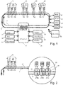
- the inventive cold-heat network 10 comprises two ring fluid lines 12, 14, in which the fluid while maintaining the selected temperature of about -10 ° C - +10 ° C, preferably from about 0 -10 ° C, is circulated.
- the fluid lines 12,14 and devices H, K, W of participants 16, 18, 20, 22 are uniform subscriber interfaces 24 a to 24 i provided, the connection between the fluid lines 12, 14 and the participants 16 to 22 existing devices H, K, W manufacture.
- a main memory 30 is provided to provide large amounts of energy when needed.
- the main storage 30 is connected to large central power sources such as a heat pump 31, a heat recovery channel 32, a cogeneration unit 34, a pyrolysis device 36, a solar air and earth absorber 38, and a heating cartridge 39.
- These devices 32 to 39 are only examples listed, it can of course also conventional power plants or wind power plants or hydroelectric power plants are used for energy.
- the temperature of the main storage medium is not increased, because the medium remains at about 0 ° C until the entire ice has melted. Thus, further heat can be removed and the temperature of the fluid in the network to be left at cold temperature. In contrast, if the heat from the large heat sources, devices 32-39, were fed directly into the fluid lines 12, 14, the temperature of the medium would rise sharply, heat losses would occur, and the cooling function would collapse.
- the device interfaces (not shown) between the devices 32-39 and the main memory 30 are so-called power interfaces that allow rapid transfer of energy from the devices 32-39 to the main memory 30.
- additional equipment can be connected directly to the fluid lines 12, 14, such as a decentralized block-type cogeneration plant 40, a cooling system 42, a heat pump 44 and a temperature 46.
- a decentralized block-type cogeneration plant 40 such as a decentralized block-type cogeneration plant 40, a cooling system 42, a heat pump 44 and a temperature 46.
- This list is only an example, for example, solar collector systems and other heat sources and-sinks are connected directly to the fluid lines 12, 14, wherein a different heat / cooling requirement can be compensated in any case by the action of the main memory 30.
- K chiller
- W heat pump
- H solar thermal roof collector or hybrid collector
- Fig. 2 shows a detail of the subscriber interfaces 24 a to 24 c of the subscriber 16.
Description
Die Erfindung betrifft ein Versorgungsnetz, an das eine Vielzahl von Teilnehmern anzuschließen ist, wobei die Teilnehmer einen unterschiedlichen Bedarf an Wärmestrom haben.The invention relates to a supply network to which a plurality of subscribers is to be connected, wherein the subscribers have a different need for heat flow.
Aus der
Die
Ein Versorgungsnetz gemäß dem Oberbegriff des Anspruchs 1 ist aus der Patentschrift
Es ist Aufgabe der Erfindung, ein Versorgungsnetz bereit zu stellen, bei dem die Energieausnutzung gegenüber herkömmlichen Systemen verbessert wird und das sehr flexible auf die Anforderungen der Teilnehmer und von Smart-Grid-Netzbetreibern reagieren kann.It is an object of the invention to provide a supply network in which the energy efficiency compared to conventional systems is improved and can respond very flexibly to the needs of subscribers and smart grid network operators.
Dazu ist das erfindungsgemäße Versorgungsnetz, an das eine Vielzahl von Teilnehmern anzuschließen ist, wobei die Teilnehmer einen unterschiedlichen Bedarf an Wärme- und Volumenstrom haben, dadurch gekennzeichnet, dass das Versorgungsnetz ein bidirektionales, kalt temperiertes Fluid-Kälte-Wärme-Netz ist, dass bidirektionale Teilnehmer-Schnittstellen bei den Teilnehmern und Zusatzgeräte-Schnittstellen für an das Netz angeschlossene Zusatzgeräte mit Energieverbrauchs- oder Energiezufuhreigenschaften vorgesehen sind, wobei die bidirektionalen Teilnehmer-Schnittstellen je einen Anschluss für thermischen Fluid-Energietransfer aufweisen, wobei es sich um einen Kältetransfer oder einen Wärmetransfer handeln kann, dass das Netz ein Kälte-Wärme-Bussystem mit Busanschlüssen für den Anschluss der Teilnehmer-Schnittstellen zu den Teilnehmern und der Zusatzgeräte-Schnittstellen an die Zusatzgeräte ist, dass ein Hauptspeicher mit einer bidirektionalen Hauptspeicher-Schnittstelle zum Netz vorgesehen ist, an den direkt diverse externe Energiequellen angeschlossen sind, dass das Netz Sensoren zur Erfassung von Energie-Daten an den Schnittstellen und den angeschlossenen Geräten sowie Datenschnittstellen zur Weitergabe der Energie-Daten aufweist umfasst; und dass eine Zentralsteuerung zur Steuerung der bidirektionalen Schnittstellen und Geräte bei den Teilnehmern und an dem Hauptspeicher vorgesehen ist.For this purpose, the supply network according to the invention, to which a plurality of participants is to be connected, wherein the participants have a different need for heat and flow, characterized in that the supply network is a bidirectional, cold-tempered fluid-cooling-heat network that bidirectional Subscriber interfaces are provided at the subscribers and auxiliary equipment interfaces for connected to the network accessories with energy consumption or Energiezufuhreigenschaften, wherein the bidirectional subscriber interfaces each have a connection for thermal fluid energy transfer, which is a cold transfer or heat transfer may be that the network is a cold-heat bus system with bus connections for the connection of the subscriber interfaces to the subscribers and the accessory interfaces to the auxiliary equipment that a main memory with a bidirectional main memory interface to Network is provided, are connected to the directly diverse external energy sources, that the network comprises sensors for detecting energy data at the interfaces and the connected devices and data interfaces for forwarding the energy data; and that a central controller is provided for controlling the bidirectional interfaces and devices at the subscribers and at the main memory.
Dadurch, dass es sich bei dem erfindungsgemäßen Versorgungsnetz um ein bidirektionelles, kalt temperiertes Fluid-Kälte-Wärme-Netz handelt, wobei die bidirektionellen Schnittstellen bei den Teilnehmern und an das Netz angeschlossenen Geräten mit Energieverbrauchs- oder Energiezuführeigenschaften vorgesehen sind, können die Teilnehmer, d.h. sowohl Verbraucher (Energie senke) als auch Lieferanten von Energie (Energiequelle) sowohl Energie von dem Netz erhalten als auch Energie an das Netz abgeben, die über das Maß der jeweils empfangenen Energie hinaus geht. Die kalte Temperierung des Fluids im Versorgungsnetz reduziert die Wärmeverluste an die Umgebung auf ein Minimum bzw. bei Temperaturen im Versorgungsnetz unter 10° C wird sogar Wärme von der Umgebung an das Versorgungsnetz abgegeben. Das Kälte-Wärme-Bus-System ermöglicht dabei die Zufuhr und die Ableitung des Fluids zu den Teilnehmern in einer steuerbaren Weise, wobei der Hauptspeicher dazu dient, den Energiebedarf dann zu decken, wenn die als Energiequelle wirkenden Teilnehmer nicht genügend Energie in das Netz einspeisen können. Das Vorhandensein des Hauptspeichers ist insbesondere dann wichtig, wenn zu Zwecken der Smard-Grid-Regulierung die energieverbrauchenden Wärmepumpen bei den Teilnehmern alle einschalten, um die individuellen Heißwasser- und Heizungsspeicher aufzuheizen, sobald das Stromnetz Überangebot an elektrischer Energie hat. Damit das Versorgungsnetz voll automatisch geregelt kann und sowohl die Entnahme von Energie als auch die Zulieferung von Energie erfasst werden kann, sind die Sensoren zur Erfassung von Energiedaten und die Datenschnittstellen vorgesehen, die es ermöglichen, dass die Zentralsteuerung die bi-direktionalen Schnittstellen und Geräte bei den Teilnehmern und den Hauptspeicher steuert.Because the supply network according to the invention is a bidirectional, cold-tempered fluid-cooling-heat network, the bidirectional interfaces being provided with energy consumption or energy supply properties to the subscribers and to the network connected to the network, the subscribers, ie Both consumers (energy sink) and suppliers of energy (energy source) both receive energy from the network as well as deliver energy to the network, which goes beyond the level of each received energy. The cold temperature of the fluid in the supply network reduces the heat losses to the environment to a minimum or at temperatures in the supply network below 10 ° C even heat from the environment is delivered to the supply network. The cold-heat bus system allows the supply and the discharge of the fluid to the participants in a controllable manner, the main memory serves to the Energy needs to be met if the participants acting as an energy source can not feed enough energy into the grid. The presence of main memory is particularly important when, for purposes of Smard grid regulation, the energy consuming heat pumps at the subscribers all turn on to heat up the individual hot water and heating storage as soon as the power grid has oversupply of electrical energy. In order to fully automatically regulate the utility grid and capture both energy harvesting and energy delivery, the sensors for collecting energy data and the data interfaces are provided which allow the central controller to integrate the bi-directional interfaces and devices controls the participants and the main memory.
Die bidirektionale Schnittstelle ermöglicht in vorteilhafter Weise eine Wärmeaufnahme, wenn Wärmebedarf am Teilnehmer vorhanden ist, und Wärmeabgabe, wenn Wärmeüberschuss am Teilnehmer vorhanden ist. Das heißt, Teilnehmer können abhängig von der Tageszeit und Jahreszeit und Wetter sowie Verbrauchsanforderungen entweder Wärmequellen sein oder auch Wärmesenken. Über die Schnittstelle fließt entweder ein positiver oder negativer Wärmestrom. Das Wärmeträgermedium im Netz dient je nach Schnittstellenbelastung als Wärmequelle und wird abgekühlt oder als Wärmesenke und wird aufgewärmt. Dabei können sich die im Netz nebeneinander an unterschiedlichen Orten befindlichen Schnittstellen unterschiedlich verhalten.The bidirectional interface advantageously allows for heat absorption when there is heat demand at the subscriber, and heat release when heat surplus is present at the subscriber. That is, subscribers may be either heat sources or heat sinks depending on the time of day and season and weather and consumption requirements. Either a positive or a negative heat flow flows through the interface. The heat transfer medium in the network is used depending on the interface load as a heat source and is cooled or as a heat sink and is warmed up. The interfaces located side by side in different locations may behave differently.
Eine besonders vorteilhafte Ausführung des erfindungsgemäßen Versorgungsnetzes ist dadurch gekennzeichnet, dass das Netz auf eine Betriebstemperatur des Fluids von + 10°C bis + 15°C ausgelegt ist, wobei diese Temperatur für die Wärmepumpen bei den Teilnehmern sehr günstig ist. Eine weitere besonders vorteilhafte Ausführung des erfindungsgemäßen Versorgungsnetzes ist dadurch gekennzeichnet, dass das Netz auf eine Betriebstemperatur des Fluids von -10°C bis 0°C ausgelegt ist, wobei diese Temperatur für die Wärmeaufnahme aus der Umgebung und für die Wärmeaufnahme aus dem Hauptspeicher sehr günstig ist. Dabei ist ein frostgeschütztes Wärmeträgerfluid im Versorgungsnetz im Einsatz.A particularly advantageous embodiment of the supply network according to the invention is characterized in that the network is designed for an operating temperature of the fluid of + 10 ° C to + 15 ° C, this temperature is very favorable for the heat pumps in the participants. Another particularly advantageous embodiment of the supply network according to the invention is characterized in that the network is designed for an operating temperature of the fluid from -10 ° C to 0 ° C, this temperature for the heat absorption from the environment and for heat absorption from the main memory very low is. Here, a frost-protected heat transfer fluid in the supply network is in use.
Erfindungsgemäß ist vorgesehen, dass die Anlage zwischen den beiden Ausführungen bzw. Betriebszuständen umschalten kann und bei Bedarf Mischzustände regeln kann.According to the invention it is provided that the system can switch between the two versions or operating conditions and can regulate mixed conditions as needed.
Eine weitere vorteilhafte Ausführung des erfindungsgemäßen Versorgungsnetzes ist dadurch gekennzeichnet, dass die Teilnehmer-Schnittstellen in Gebäude der Teilnehmer integriert sind, wobei das Netz zu den Gebäuden führt, oder dass die Teilnehmer-Schnittstellen in das Netz integriert sind, wobei Leitungen von den Schnittstellen zu Gebäuden der Teilnehmer führen. Das Versorgungsnetz kann dadurch in vorteilhafter Weise an lokale Gegebenheiten bei den Teilnehmern angepasst werden.A further advantageous embodiment of the supply network according to the invention is characterized in that the subscriber interfaces are integrated into buildings of the participants, wherein the network leads to the buildings, or that the subscriber interfaces are integrated into the network, said lines from the interfaces to buildings of the participants. The supply network can be adapted in an advantageous manner to local conditions in the participants.
Eine weitere vorteilhafte Ausführung des erfindungsgemäßen Versorgungsnetzes ist dadurch gekennzeichnet, dass die Teilnehmer-Schnittstellen bzw. die Anschlüsse zu den Teilnehmern und den angeschlossenen Geräten und die Leitungen, die zu unterschiedlichen Teilnehmern und Geräten führen, genormt, vorzugsweise einheitlich ausgeführt sind. Da die Anschlüsse aller Verbraucher und Quellen im Netz einheitlich gestaltet sind, insbesondere bezüglich Durchmesser, Abmessungen und räumliche Anordnungen, ergibt sich eine erhebliche Vereinfachung der Installation und eine entsprechende Kostenersparnis. Außerdem hat dies den Vorteil, dass das Netz ohne Probleme jederzeit erweitert werden kann oder Verbraucher ausgetauscht werden können. Die Einheitlichkeit ist auch vorteilhaft, um die Schnittstellen zentral ansteuern zu können.A further advantageous embodiment of the supply network according to the invention is characterized in that the subscriber interfaces or the connections to the subscribers and the connected devices and the lines that lead to different subscribers and devices are standardized, preferably uniformly executed. Since the connections of all consumers and sources in the network are designed uniformly, in particular in terms of diameter, dimensions and spatial arrangements, there is a considerable simplification of the installation and a corresponding cost savings. In addition, this has the advantage that the network can be expanded at any time without problems or consumers can be replaced. The uniformity is also advantageous in order to be able to control the interfaces centrally.
Eine weitere vorteilhafte Ausführung des erfindungsgemäßen Versorgungsnetzes ist dadurch gekennzeichnet, dass die bei den Teilnehmern an das Netz angeschlossenen Geräte eine Kühlanlage und/oder eine Wärmepumpe und/oder ein solarthermischer Dachkollektor und/oder ein Hybridkollektor umfassen. Dies sind vorteilhafte Beispiele für Wärmequellen bzw. Wärmesenken. Es können jedoch auch weitere Wärmequellen oder Wärmesenken integriert werden.A further advantageous embodiment of the supply network according to the invention is characterized in that the devices connected to the network at the participants include a cooling system and / or a heat pump and / or a solar thermal roof collector and / or a hybrid collector. These are advantageous examples of heat sources or heat sinks. However, other heat sources or heat sinks can also be integrated.
Eine weitere vorteilhafte Ausführung des erfindungsgemäßen Versorgungsnetzes ist dadurch gekennzeichnet, dass der Hauptspeicher ein vereisbarer Speicher ist, der mit einem vereisbaren Medium gefüllt ist, insbesondere mit Wasser. Das Speichersystem mit direkten Wärmequellen erlaubt die Kalt-Temperierung des Kälte-Wärme-Netzes. Die Einspeisung von Wärme aus externen Quellen direkt in den Speicher hat den Vorteil, dass die Umlauftemperatur auch bei starker Wärmezufuhr temperiert bei z.B. 10 Grad bleiben kann. Die extern zugeführte Wärme wirkt zunächst nur im Speicher selbst und taut dort gespeichertes Eis auf, ohne dass sich die Temperatur sofort stark erhöht.A further advantageous embodiment of the supply network according to the invention is characterized in that the main storage is an iceable storage, which is filled with an icing medium, in particular with water. The storage system with direct heat sources allows the cold-temperature control of the cold-heat network. The feed of heat from external sources directly into the store has the advantage that the circulating temperature is maintained at a high temperature even at high heat input. 10 degrees can stay. The externally supplied heat acts initially only in the storage itself and thaws stored ice there, without the temperature increases immediately.
Eine weitere vorteilhafte Ausführung des erfindungsgemäßen Versorgungsnetzes ist dadurch gekennzeichnet, dass der Hauptspeicher Hauptspeicher-Schnittstellen zum direkten Anschluss beispielsweise an ein Heizkraftwerk und/oder eine photovoltaische Solaranlage und/oder eine Solarthermieanlage und/oder eine Windkraftanlage aufweist. Würde die Wärme aus den großen Wärmequellen in das Leitungsnetz eingespeist, würde die Temperatur des Fluids im Netz stark ansteigen, Wärmeverluste würden auftreten und die Kühlfunktion würde zusammenbrechen. Insbesondere würden Kühlanlagen der Teilnehmer nicht mehr mit ausreichend kaltem sondern mit zu warmem Fluid versorgt werden.A further advantageous embodiment of the supply network according to the invention is characterized in that the main memory main memory interfaces for direct connection, for example to a heating plant and / or a photovoltaic solar system and / or a solar thermal system and / or a wind turbine. If the heat from the large heat sources fed into the network, the temperature of the fluid in the network would rise sharply, heat losses would occur and the cooling function would collapse. In particular, cooling systems of the participants would no longer be supplied with sufficiently cold but too warm fluid.
Eine weitere vorteilhafte Ausführung des erfindungsgemäßen Versorgungsnetzes ist dadurch gekennzeichnet, dass die direkten Hauptspeicher-Schnittstellen am Hauptspeicher Leistungsanschlüsse sind, wobei in vorteilhafter Weise ermöglicht wird, dass der Hauptspeicher bei Bedarf schnell aufgeheizt werden kann, (Netz-Spitzen-Last Management, Smart-Grid-Minutenreserve, ohne dabei das Netz direkt zu beeinflussen. Eine schnelle Aufheizung kann dann erforderlich sein, wenn eine oder mehrere Energiequellen oder -senken ausfallen. Um dem Hauptspeicher wieder Wärme zuzuführen, müssen die Leistungsanschlüsse direkt in den Hauptspeicher erfolgen. Dadurch wird in vorteilhafter Weise erreicht, dass die Temperatur des Fluids im Netz nicht zu hoch wird und jegliche Kühlfunktion bei den Teilnehmern versagt. Somit wird die Kälteversorgung der direkt angeschlossenen Kälteverbraucher sichergestellt. Des Weiteren hat der Hauptspeicher die Funktion eines thermischen Energiereservoirs für den Fall, dass aus Gründen des Wärmebedarfs bei den Teilnehmern oder des Energieüberschusses im Elektrizitätsnetz die Wärmepumpen viel Wärme aus dem Versorgungsnetz entnehmen und auf höheres Temperaturniveau transferieren. Diese Funktionalität ist von großer Bedeutung als Flexibilität im Sinne der Smart Grid Steuerung von Stromverbrauchern.A further advantageous embodiment of the supply network according to the invention is characterized in that the direct main memory interfaces on the main memory are power terminals, which advantageously allows the main memory to be heated up quickly if required (network peak load management, smart grid Rapid heating may be required when one or more energy sources or sinks fail, and to supply heat to the main memory, the power connections must be made directly to main memory ensures that the temperature of the fluid in the network does not become too high and any cooling function at the subscribers fails, thus ensuring the refrigeration of the directly connected refrigeration consumers. that due to the heat demand at the participants or the excess energy in the electricity grid, the heat pumps remove much heat from the supply network and transfer to a higher temperature level. This functionality is very important as flexibility in terms of smart grid control of power consumers.
Eine weitere vorteilhafte Ausführung des erfindungsgemäßen Versorgungsnetzes ist dadurch gekennzeichnet, dass das Netz eine Parallelschaltung der Teilnehmer-Schnittstellen zu den Teilnehmern und der Zusatzgeräte-Schnittstellen zu den Geräten aufweist. Durch die Parallelschaltung wird in vorteilhafter Weise erreicht, dass die einzelnen Geräte bei den Teilnehmern oder auch direkt an das Netz angeschlossene Geräte unabhängig voneinander angesteuert werden können.A further advantageous embodiment of the supply network according to the invention is characterized in that the network has a parallel connection of the subscriber interfaces to the subscribers and the auxiliary device interfaces to the devices. Due to the parallel connection is achieved in an advantageous manner that the individual devices in the participants or directly connected to the network devices can be controlled independently.
Eine weitere vorteilhafte Ausführung des erfindungsgemäßen Versorgungsnetzes ist dadurch gekennzeichnet, dass die an das Netz angeschlossenen Zusatzgeräte ein dezentrales Block-Heizkraftwerk und/oder eine Solarstromanlage und/oder eine Kühlanlage und/oder eine Wärmepumpe aufweist. Das erfindungsgemäße Versorgungsnetz ist in vorteilhafter Weise flexibel genug, um nicht nur Geräte in Häusern von Teilnehmern, sondern auch externe Geräte, wie Blockheizkraftwerke oder dergleichen zu integrieren. Es können auch weitere Energiequellen oder -senken integriert werden in das Netz.A further advantageous embodiment of the supply network according to the invention is characterized in that the auxiliary equipment connected to the network has a decentralized block heating plant and / or a solar power system and / or a cooling system and / or a heat pump. The supply network according to the invention is advantageously flexible enough to integrate not only devices in participants' homes, but also external devices such as combined heat and power plants or the like. Other energy sources or sinks can also be integrated into the grid.
Eine weitere vorteilhafte Ausführung des erfindungsgemäßen Versorgungsnetzes ist dadurch gekennzeichnet, dass zusätzlich eine Wärmetauscheranlage zur Temperierung des Fluids im Netz an das Netz angeschlossen ist. Die Wärmetauscheranlage ist in vorteilhafter Weise ein weiteres Mittel, um das Fluid im Netz in seiner Temperatur auszugleichen.A further advantageous embodiment of the supply network according to the invention is characterized in that in addition a heat exchanger system for controlling the temperature of the fluid in the network is connected to the network. The heat exchanger system is advantageously a further means to compensate for the fluid in the network in its temperature.
Weitere Vorteile, Merkmale und Anwendungsmöglichkeiten der vorliegenden Erfindung ergeben sich aus der nachfolgenden Beschreibung in Verbindung mit den in den Zeichnungen dargestellten Ausführungsbeispielen.Further advantages, features and possible applications of the present invention will become apparent from the following description in conjunction with the embodiments illustrated in the drawings.
Es zeigen:
- Fig. 1
- ein Ausführungsbeispiel des erfindungsgemäßen Versorgungsnetzes, und
- Fig. 2
- eine Detaildarstellung zu den bei dem erfindungsgemäßen Versorgungsnetz verwendeten Teilnehmer-Schnittstellen.
- Fig. 1
- an embodiment of the supply network according to the invention, and
- Fig. 2
- a detailed representation of the subscriber interfaces used in the supply network according to the invention.
Wie aus
Der Hauptspeicher 30 ist mit großen zentralen Energiequellen, beispielsweise eine Wärmepumpe 31, einem Wärmerückgewinnungs-Kanal 32, einer KWK-Einheit 34, ein Pyrolyse-Einrichtung 36, einem Solarluft- und Erdabsorber 38 und einer Heizpatrone 39 verbunden. Diese Geräte 32 bis 39 sind nur beispielhaft aufgeführt, es können selbstverständlich auch konventionelle Kraftwerke oder Windkraftwerke oder Wasserkraftwerke zur Energieversorgung eingesetzt werden.The
Wenn dem Hauptspeicher 30, der als Eisspeicher ausgebildet ist, Energie zugeführt wird, wird die Temperatur des Hauptspeichermediums nicht erhöht, denn das Medium bleibt bei ca. 0° C bis das gesamte Eis geschmolzen ist. Somit kann weiterhin Wärme entnommen und die Temperatur des Fluids im Netz auf Kalttemperatur belassen werden. Im Gegensatz dazu würde, wenn die Wärme aus den großen Wärmequellen, nämlich den Geräten 32 bis 39, direkt in die Fluidleitungen 12, 14 eingespeist würde, würde die Temperatur des Mediums stark ansteigen, Wärmeverluste würden auftreten und die Kühlfunktion würde zusammenbrechen.If energy is supplied to the
Die (nicht gezeigten) Geräte-Schnittstellen zwischen den Geräten 32 bis 39 und dem Hauptspeicher 30 sind sogenannte Leistungsschnittstellen, die eine schnelle Energieübertragung von den Geräten 32 bis 39 in den Hauptspeicher 30 gestatten.The device interfaces (not shown) between the devices 32-39 and the
Schließlich können auch Zusatzgeräte direkt an die Fluidleitungen 12, 14 angeschlossen werden, wie beispielsweise ein dezentrales Block-Heizkraftwerk 40, eine Kühlanlage 42, eine Wärmepumpe 44 und eine Temperierungseinrichtung 46. Auch diese Aufzählung ist nur beispielhaft, so können beispielsweise Sonnenkollektorsysteme und auch andere Wärmequellen und auch -senken direkt an die Fluidleitungen 12, 14 angeschlossen werden, wobei ein unterschiedlicher Wärme-/Kältebedarf jedenfalls durch die Wirkung des Hauptspeichers 30 ausgeglichen werden kann.Finally, additional equipment can be connected directly to the
Aus
Geräte, die bei den Teilnehmern 16 bis 22 vorhanden sind, sind mit "K" für Kältemaschine, "W" für Wärmepumpe und "H" für solarthermischer Dachkollektor bzw. Hybridkollektor (PVTh) bezeichnet. Es ist ersichtlich, dass die Teilnehmer 16 bis 22 mit unterschiedlichen Geräten K. W, H ausgerüstet sein können, wobei die einheitlichen Schnittstellen und Sensoren (nicht gezeigt) sowie Betriebsschalter (nicht gezeigt) an den Schnittstellen bzw. Geräten sowie Datenschnittstellen (nicht gezeigt) dafür sorgen, dass das Versorgungsnetz 10 durch eine zentrale Steueranlage 50 gesteuert werden kann, die beispielsweise über Funk mit den Datenschnittstellen in Verbindung steht.Devices that are present in the
Claims (14)
- Supply network (10) to which a multiplicity of subscribers (16-22) are connected, wherein the subscribers (16-22) have different heat and volume flow requirements, and the supply network (10) is a bidirectional fluid cooling/heating network maintained at a cool temperature, wherein bidirectional subscriber interfaces (24a-24i) are provided at the subscribers (16 - 22) and auxiliary unit interfaces are provided for auxiliary units (40 - 44) which are connected to the network and have energy consumption or energy supply properties, wherein the bidirectional subscriber interfaces (24a-24i) each have a connection for thermal fluid/energy transfer, which transfer may be a cold transfer or a heat transfer, wherein the network is a cooling/heating bus system having bus connections for connection of the subscriber interfaces (24a - 24i) to the subscribers (16 - 22) and of the auxiliary unit interfaces to the auxiliary units (40 - 44), and a main storage device (30) having a bidirectional main storage device interface to the network is provided, wherein the network has sensors for acquiring energy data at all interfaces and at the connected units as well as data interfaces for forwarding the energy data, and a central controller (50) is provided for controlling the bidirectional interfaces and units at the subscribers (16 - 22),
characterised in that
various external energy sources (32 - 38) are directly connected to the main storage device (30) and
the central controller (50) is also provided for controlling the bidirectional interfaces at the main storage device (30). - Supply network (10) according to claim 1, characterised in that the network is designed for an operating temperature of the fluid of between -10°C and +10°C.
- Supply network (10) according to claim 2, characterised in that the central controller is designed to be able to switch over between different temperature levels.
- Supply network (10) according to claim 1 or 2, characterised in that the subscriber interfaces (24a - 24i) are integrated into buildings of the subscribers (16 - 22), wherein the network leads to the buildings.
- Supply network (10) according to claim 1 or 2, characterised in that the subscriber interfaces (24a - 24i) are integrated into the network, wherein lines lead from the subscriber interfaces (24a-24i) to buildings of the subscribers (16 - 22).
- Supply network (10) according to any one of claims 1 to 5, characterised in that the subscriber interfaces (24a - 24i) or the connections to the subscribers (16 - 22) and to the connected units are of standardised, preferably uniform, construction.
- Supply network (10) according to any one of claims 1 to 6, characterised in that lines and the interfaces to which the different units are to be connected at the subscribers (16-22) are of uniformly configured, standardised, preferably identical, construction.
- Supply network (10) according to claim 1, characterised in that the units connected to the network at the subscribers (16 - 22) comprise a cooling system and/or a heat pump and/or a solar thermal roof collector and/or a hybrid collector.
- Supply network (10) according to claim 1, characterised in that the main storage device (30) is a freezable main storage device (30), which is filled with a freezable medium, especially water.
- Supply network (10) according to claim 1 or 9, characterised in that the main storage device (30) has main storage device interfaces for direct connection to a heat pump (31) and/or a heat-recovery channel (32) and/or a CHP unit (34) and/or a pyrolysis device (36) and/or a solar air and ground absorber (38) and/or a heating cartridge (39).
- Supply network (10) according to claim 10, characterised in that the direct main storage device interfaces at the main storage device (30) are power connections which enable the main storage device (30) to be heated quickly if required.
- Supply network (10) according to claim 1, characterised in that the network has parallel connection of the subscriber interfaces (24a - 24i) to the subscribers (16 - 22) and of the auxiliary unit interfaces to the auxiliary units (40 - 44).
- Supply network (10) according to claim 1, characterised in that the auxiliary units (40 - 44) connected to the network have a local modular CHP system (40) and/or a cooling system (42) and/or a heat pump (44) and/or a solar power system.
- Supply network (10) according to claim 1 or 13, characterised in that a heat exchanger system (46) for controlling the temperature of the fluid in the network is additionally connected to the network.
Applications Claiming Priority (1)
| Application Number | Priority Date | Filing Date | Title |
|---|---|---|---|
| DE202012103891U DE202012103891U1 (en) | 2012-10-11 | 2012-10-11 | supply network |
Publications (3)
| Publication Number | Publication Date |
|---|---|
| EP2719977A2 EP2719977A2 (en) | 2014-04-16 |
| EP2719977A3 EP2719977A3 (en) | 2015-12-09 |
| EP2719977B1 true EP2719977B1 (en) | 2017-03-29 |
Family
ID=47503546
Family Applications (1)
| Application Number | Title | Priority Date | Filing Date |
|---|---|---|---|
| EP13188189.8A Active EP2719977B1 (en) | 2012-10-11 | 2013-10-10 | Supply network |
Country Status (4)
| Country | Link |
|---|---|
| EP (1) | EP2719977B1 (en) |
| DE (1) | DE202012103891U1 (en) |
| ES (1) | ES2629508T3 (en) |
| PL (1) | PL2719977T3 (en) |
Families Citing this family (14)
| Publication number | Priority date | Publication date | Assignee | Title |
|---|---|---|---|---|
| DE102013003206A1 (en) * | 2013-02-26 | 2014-08-28 | Franz Maierhofer | District heat transfer device for a building and district heating system for supplying buildings with heat energy |
| DE102013214891A1 (en) * | 2013-07-30 | 2015-02-05 | Siemens Aktiengesellschaft | Thermal engineering interconnection of a geothermal energy source with a district heating network |
| KR101549657B1 (en) * | 2013-11-08 | 2015-09-03 | 한국에너지기술연구원 | System and method for controlling of heat exchange between district heating networks |
| DE102014105743A1 (en) * | 2014-04-23 | 2014-09-04 | Enerpipe Gmbh | Buffer memory system for use in distributed buffer memory system in near or remote heating network, has line assembly to connect flow to return through buffer memory and control unit to control switching element depending on network sizes |
| DE102014014325A1 (en) * | 2014-10-01 | 2016-04-07 | Stiebel Eltron Gmbh & Co. Kg | A heat pump apparatus and method of controlling a heat pump apparatus |
| GB2544063B (en) * | 2015-11-03 | 2018-04-11 | Basic Holdings | Distributed heat pump network |
| EP3267118A1 (en) * | 2016-07-07 | 2018-01-10 | E.ON Sverige AB | Heating system |
| EP3267119A1 (en) * | 2016-07-07 | 2018-01-10 | E.ON Sverige AB | Combined heating and cooling system |
| EP3273168A1 (en) * | 2016-07-19 | 2018-01-24 | E.ON Sverige AB | Method for controlling heat transfer between a local cooling system and a local heating system |
| EP3273169A1 (en) * | 2016-07-19 | 2018-01-24 | E.ON Sverige AB | Heat transfer system |
| EP3553396A1 (en) * | 2018-04-09 | 2019-10-16 | JFE REBARO Fernwärmetechnik GmbH | District heating discharge station |
| GB2575310B (en) * | 2018-07-06 | 2020-10-07 | Basic Holdings | Distributed heating and cooling network |
| DE102019134349A1 (en) * | 2019-12-13 | 2021-06-17 | Wolfgang Jaske und Dr. Peter Wolf GbR (vertretungsberechtigter Gesellschafter: Wolfgang Jaske, 49811 Lingen; Dr. Peter Wolf, 26209 Hatten) | Building system for air conditioning and heat supply |
| EP3916309A1 (en) * | 2020-05-26 | 2021-12-01 | E.ON Sverige AB | Controlling of a district thermal energy distribution system |
Citations (4)
| Publication number | Priority date | Publication date | Assignee | Title |
|---|---|---|---|---|
| CH692216A5 (en) | 1994-09-26 | 2002-03-15 | Sandler Energietechnik | Communal heating system using central bus=bar principle for flow distribution |
| WO2006045551A2 (en) | 2004-10-26 | 2006-05-04 | Rohr Alex | Energy accumulator, heat exchanger system for an energy accumulator, energy storage system and corresponding method |
| WO2010145040A1 (en) | 2009-06-16 | 2010-12-23 | Dec Design Mechanical Consultants Ltd. | District energy sharing system |
| DE102011001273A1 (en) | 2011-03-15 | 2012-09-20 | Isocal Heizkühlsysteme Gmbh | Storage tank for an energy storage system and energy storage system with such storage tanks |
Family Cites Families (1)
| Publication number | Priority date | Publication date | Assignee | Title |
|---|---|---|---|---|
| DE102007049621A1 (en) | 2007-10-17 | 2009-04-23 | Ingenieurgesellschaft Dr. Siekmann + Partner Mbh | Method for supplying heat energy and cooling energy to e.g. residential building, involves utilizing excess heat energy, and selecting design of combination-power-heat coupling such that maximum utilization rate is achieved |
-
2012
- 2012-10-11 DE DE202012103891U patent/DE202012103891U1/en not_active Expired - Lifetime
-
2013
- 2013-10-10 ES ES13188189.8T patent/ES2629508T3/en active Active
- 2013-10-10 EP EP13188189.8A patent/EP2719977B1/en active Active
- 2013-10-10 PL PL13188189T patent/PL2719977T3/en unknown
Patent Citations (4)
| Publication number | Priority date | Publication date | Assignee | Title |
|---|---|---|---|---|
| CH692216A5 (en) | 1994-09-26 | 2002-03-15 | Sandler Energietechnik | Communal heating system using central bus=bar principle for flow distribution |
| WO2006045551A2 (en) | 2004-10-26 | 2006-05-04 | Rohr Alex | Energy accumulator, heat exchanger system for an energy accumulator, energy storage system and corresponding method |
| WO2010145040A1 (en) | 2009-06-16 | 2010-12-23 | Dec Design Mechanical Consultants Ltd. | District energy sharing system |
| DE102011001273A1 (en) | 2011-03-15 | 2012-09-20 | Isocal Heizkühlsysteme Gmbh | Storage tank for an energy storage system and energy storage system with such storage tanks |
Also Published As
| Publication number | Publication date |
|---|---|
| DE202012103891U1 (en) | 2012-12-10 |
| ES2629508T3 (en) | 2017-08-10 |
| PL2719977T3 (en) | 2017-09-29 |
| EP2719977A2 (en) | 2014-04-16 |
| EP2719977A3 (en) | 2015-12-09 |
Similar Documents
| Publication | Publication Date | Title |
|---|---|---|
| EP2719977B1 (en) | Supply network | |
| DE102008040028A1 (en) | Energy conversion system for supplying e.g. electrical energy, to e.g. consumer in residential building, has Peltier converter receiving electrical energy from battery and/or another Peltier converter and delivering heat energy to consumer | |
| DE102011001273A1 (en) | Storage tank for an energy storage system and energy storage system with such storage tanks | |
| DE102019000430B4 (en) | Process for achieving very low return temperatures using a heat pump, heating arrangement for carrying out the process, and system for heating and cooling distribution networks | |
| DE102011090141A1 (en) | Method and device for using electrical energy of a device connected to a household power network for generating renewable electrical energy | |
| EP3667182B1 (en) | Heat pump assembly | |
| DE102008008652A1 (en) | Thermal electrical accumulator for use in solar thermal plants for wash water heating and heating backup, comprises heat reservoir and cold reservoir, which are thermally separated, and arrangement of thermoelectric generators are provided | |
| DE102007050446A1 (en) | Indirectly evaporating heat pump, has heat source circuit with external air heat circuit and geo heat circuit having different energy sources, where heat circuits are connected with each other and with refrigerant circuit | |
| EP2770264B1 (en) | District heat transfer device for a building and district heating system for supplying buildings with thermal energy | |
| DE102010016163A1 (en) | Solar energy utilizing system for use in e.g. office building, has thermoelectric generator arranged such that sides are arranged in thermal contact with module and geothermal energy storage by fluid circuits, respectively | |
| EP2764298B1 (en) | Cogeneration plant and operation method therefor | |
| EP2492599B1 (en) | Heating assembly with biomass furnace and heat pump | |
| DE102012112962A1 (en) | System for heating industrial thermal water, has controllable pump arranged in circulation line, electrical heating element arranged in heater arrangement with switches, and pump connected with steering control unit | |
| DE102013003469A1 (en) | Method for room- or building heating under partial use of renewable, volatile electrical energy, involves supplying electrical energy in electro-thermal storage for heating room or building by using controller | |
| EP2795199A2 (en) | Heat supply system and heat supply method | |
| DE102017124030A1 (en) | Energy storage system | |
| CH712294B1 (en) | Thermal energy system. | |
| DE102016107627B4 (en) | Arrangement for hot water and heating water production with at least partial use of regenerative electrical energy | |
| DE102012212040B4 (en) | Heat pump system and method for providing hot water | |
| DE102012104996A1 (en) | Energy concept system used for supplying power to e.g. refrigerator in building, has heat pump which distributes thermal energy to photovoltaic module through solar thermal collector | |
| DE102012018797B4 (en) | Heat energy supply system and method for their operation | |
| WO2015007603A1 (en) | Use of waste heat of high-temperature batteries | |
| EP2942570B1 (en) | Geothermal heating installation | |
| DE202013101076U1 (en) | Hot water system for heating drinking water and / or heating water | |
| EP3572733A1 (en) | Heat pump heating device for heating of a building or an industrial water storage device |
Legal Events
| Date | Code | Title | Description |
|---|---|---|---|
| PUAI | Public reference made under article 153(3) epc to a published international application that has entered the european phase |
Free format text: ORIGINAL CODE: 0009012 |
|
| AK | Designated contracting states |
Kind code of ref document: A2 Designated state(s): AL AT BE BG CH CY CZ DE DK EE ES FI FR GB GR HR HU IE IS IT LI LT LU LV MC MK MT NL NO PL PT RO RS SE SI SK SM TR |
|
| AX | Request for extension of the european patent |
Extension state: BA ME |
|
| PUAL | Search report despatched |
Free format text: ORIGINAL CODE: 0009013 |
|
| AK | Designated contracting states |
Kind code of ref document: A3 Designated state(s): AL AT BE BG CH CY CZ DE DK EE ES FI FR GB GR HR HU IE IS IT LI LT LU LV MC MK MT NL NO PL PT RO RS SE SI SK SM TR |
|
| AX | Request for extension of the european patent |
Extension state: BA ME |
|
| RIC1 | Information provided on ipc code assigned before grant |
Ipc: F24D 11/02 20060101ALI20151105BHEP Ipc: G05B 15/02 20060101ALI20151105BHEP Ipc: F24D 19/10 20060101ALI20151105BHEP Ipc: F24D 11/00 20060101ALI20151105BHEP Ipc: F25D 17/02 20060101AFI20151105BHEP Ipc: F25B 30/06 20060101ALI20151105BHEP |
|
| 17P | Request for examination filed |
Effective date: 20160608 |
|
| RBV | Designated contracting states (corrected) |
Designated state(s): AL AT BE BG CH CY CZ DE DK EE ES FI FR GB GR HR HU IE IS IT LI LT LU LV MC MK MT NL NO PL PT RO RS SE SI SK SM TR |
|
| GRAP | Despatch of communication of intention to grant a patent |
Free format text: ORIGINAL CODE: EPIDOSNIGR1 |
|
| STAA | Information on the status of an ep patent application or granted ep patent |
Free format text: STATUS: GRANT OF PATENT IS INTENDED |
|
| INTG | Intention to grant announced |
Effective date: 20161130 |
|
| RIN1 | Information on inventor provided before grant (corrected) |
Inventor name: DR. EDGAR SCHMIEDER Inventor name: ARNOLD SCHMID |
|
| RAP1 | Party data changed (applicant data changed or rights of an application transferred) |
Owner name: SCHMID, ARNOLD |
|
| GRAS | Grant fee paid |
Free format text: ORIGINAL CODE: EPIDOSNIGR3 |
|
| GRAA | (expected) grant |
Free format text: ORIGINAL CODE: 0009210 |
|
| STAA | Information on the status of an ep patent application or granted ep patent |
Free format text: STATUS: THE PATENT HAS BEEN GRANTED |
|
| AK | Designated contracting states |
Kind code of ref document: B1 Designated state(s): AL AT BE BG CH CY CZ DE DK EE ES FI FR GB GR HR HU IE IS IT LI LT LU LV MC MK MT NL NO PL PT RO RS SE SI SK SM TR |
|
| REG | Reference to a national code |
Ref country code: GB Ref legal event code: FG4D Free format text: NOT ENGLISH |
|
| REG | Reference to a national code |
Ref country code: CH Ref legal event code: EP |
|
| REG | Reference to a national code |
Ref country code: AT Ref legal event code: REF Ref document number: 880161 Country of ref document: AT Kind code of ref document: T Effective date: 20170415 |
|
| REG | Reference to a national code |
Ref country code: IE Ref legal event code: FG4D Free format text: LANGUAGE OF EP DOCUMENT: GERMAN |
|
| REG | Reference to a national code |
Ref country code: DE Ref legal event code: R096 Ref document number: 502013006786 Country of ref document: DE |
|
| REG | Reference to a national code |
Ref country code: NL Ref legal event code: FP |
|
| PG25 | Lapsed in a contracting state [announced via postgrant information from national office to epo] |
Ref country code: GR Free format text: LAPSE BECAUSE OF FAILURE TO SUBMIT A TRANSLATION OF THE DESCRIPTION OR TO PAY THE FEE WITHIN THE PRESCRIBED TIME-LIMIT Effective date: 20170630 Ref country code: NO Free format text: LAPSE BECAUSE OF FAILURE TO SUBMIT A TRANSLATION OF THE DESCRIPTION OR TO PAY THE FEE WITHIN THE PRESCRIBED TIME-LIMIT Effective date: 20170629 Ref country code: HR Free format text: LAPSE BECAUSE OF FAILURE TO SUBMIT A TRANSLATION OF THE DESCRIPTION OR TO PAY THE FEE WITHIN THE PRESCRIBED TIME-LIMIT Effective date: 20170329 Ref country code: FI Free format text: LAPSE BECAUSE OF FAILURE TO SUBMIT A TRANSLATION OF THE DESCRIPTION OR TO PAY THE FEE WITHIN THE PRESCRIBED TIME-LIMIT Effective date: 20170329 Ref country code: LT Free format text: LAPSE BECAUSE OF FAILURE TO SUBMIT A TRANSLATION OF THE DESCRIPTION OR TO PAY THE FEE WITHIN THE PRESCRIBED TIME-LIMIT Effective date: 20170329 |
|
| REG | Reference to a national code |
Ref country code: ES Ref legal event code: FG2A Ref document number: 2629508 Country of ref document: ES Kind code of ref document: T3 Effective date: 20170810 |
|
| PG25 | Lapsed in a contracting state [announced via postgrant information from national office to epo] |
Ref country code: SE Free format text: LAPSE BECAUSE OF FAILURE TO SUBMIT A TRANSLATION OF THE DESCRIPTION OR TO PAY THE FEE WITHIN THE PRESCRIBED TIME-LIMIT Effective date: 20170329 Ref country code: BG Free format text: LAPSE BECAUSE OF FAILURE TO SUBMIT A TRANSLATION OF THE DESCRIPTION OR TO PAY THE FEE WITHIN THE PRESCRIBED TIME-LIMIT Effective date: 20170629 Ref country code: RS Free format text: LAPSE BECAUSE OF FAILURE TO SUBMIT A TRANSLATION OF THE DESCRIPTION OR TO PAY THE FEE WITHIN THE PRESCRIBED TIME-LIMIT Effective date: 20170329 Ref country code: LV Free format text: LAPSE BECAUSE OF FAILURE TO SUBMIT A TRANSLATION OF THE DESCRIPTION OR TO PAY THE FEE WITHIN THE PRESCRIBED TIME-LIMIT Effective date: 20170329 |
|
| REG | Reference to a national code |
Ref country code: FR Ref legal event code: PLFP Year of fee payment: 5 |
|
| PG25 | Lapsed in a contracting state [announced via postgrant information from national office to epo] |
Ref country code: SK Free format text: LAPSE BECAUSE OF FAILURE TO SUBMIT A TRANSLATION OF THE DESCRIPTION OR TO PAY THE FEE WITHIN THE PRESCRIBED TIME-LIMIT Effective date: 20170329 Ref country code: CZ Free format text: LAPSE BECAUSE OF FAILURE TO SUBMIT A TRANSLATION OF THE DESCRIPTION OR TO PAY THE FEE WITHIN THE PRESCRIBED TIME-LIMIT Effective date: 20170329 Ref country code: RO Free format text: LAPSE BECAUSE OF FAILURE TO SUBMIT A TRANSLATION OF THE DESCRIPTION OR TO PAY THE FEE WITHIN THE PRESCRIBED TIME-LIMIT Effective date: 20170329 Ref country code: EE Free format text: LAPSE BECAUSE OF FAILURE TO SUBMIT A TRANSLATION OF THE DESCRIPTION OR TO PAY THE FEE WITHIN THE PRESCRIBED TIME-LIMIT Effective date: 20170329 |
|
| PG25 | Lapsed in a contracting state [announced via postgrant information from national office to epo] |
Ref country code: IS Free format text: LAPSE BECAUSE OF FAILURE TO SUBMIT A TRANSLATION OF THE DESCRIPTION OR TO PAY THE FEE WITHIN THE PRESCRIBED TIME-LIMIT Effective date: 20170729 Ref country code: SM Free format text: LAPSE BECAUSE OF FAILURE TO SUBMIT A TRANSLATION OF THE DESCRIPTION OR TO PAY THE FEE WITHIN THE PRESCRIBED TIME-LIMIT Effective date: 20170329 Ref country code: PT Free format text: LAPSE BECAUSE OF FAILURE TO SUBMIT A TRANSLATION OF THE DESCRIPTION OR TO PAY THE FEE WITHIN THE PRESCRIBED TIME-LIMIT Effective date: 20170731 |
|
| REG | Reference to a national code |
Ref country code: DE Ref legal event code: R026 Ref document number: 502013006786 Country of ref document: DE |
|
| PLBI | Opposition filed |
Free format text: ORIGINAL CODE: 0009260 |
|
| PLAX | Notice of opposition and request to file observation + time limit sent |
Free format text: ORIGINAL CODE: EPIDOSNOBS2 |
|
| PG25 | Lapsed in a contracting state [announced via postgrant information from national office to epo] |
Ref country code: DK Free format text: LAPSE BECAUSE OF FAILURE TO SUBMIT A TRANSLATION OF THE DESCRIPTION OR TO PAY THE FEE WITHIN THE PRESCRIBED TIME-LIMIT Effective date: 20170329 |
|
| 26 | Opposition filed |
Opponent name: VIESSMANN EIS-ENERGIESPEICHER GMBH Effective date: 20171229 |
|
| PLBB | Reply of patent proprietor to notice(s) of opposition received |
Free format text: ORIGINAL CODE: EPIDOSNOBS3 |
|
| PG25 | Lapsed in a contracting state [announced via postgrant information from national office to epo] |
Ref country code: MC Free format text: LAPSE BECAUSE OF FAILURE TO SUBMIT A TRANSLATION OF THE DESCRIPTION OR TO PAY THE FEE WITHIN THE PRESCRIBED TIME-LIMIT Effective date: 20170329 Ref country code: SI Free format text: LAPSE BECAUSE OF FAILURE TO SUBMIT A TRANSLATION OF THE DESCRIPTION OR TO PAY THE FEE WITHIN THE PRESCRIBED TIME-LIMIT Effective date: 20170329 |
|
| REG | Reference to a national code |
Ref country code: IE Ref legal event code: MM4A |
|
| PG25 | Lapsed in a contracting state [announced via postgrant information from national office to epo] |
Ref country code: LU Free format text: LAPSE BECAUSE OF NON-PAYMENT OF DUE FEES Effective date: 20171010 |
|
| PG25 | Lapsed in a contracting state [announced via postgrant information from national office to epo] |
Ref country code: MT Free format text: LAPSE BECAUSE OF FAILURE TO SUBMIT A TRANSLATION OF THE DESCRIPTION OR TO PAY THE FEE WITHIN THE PRESCRIBED TIME-LIMIT Effective date: 20170329 |
|
| REG | Reference to a national code |
Ref country code: FR Ref legal event code: PLFP Year of fee payment: 6 |
|
| PG25 | Lapsed in a contracting state [announced via postgrant information from national office to epo] |
Ref country code: IE Free format text: LAPSE BECAUSE OF NON-PAYMENT OF DUE FEES Effective date: 20171010 |
|
| PLAB | Opposition data, opponent's data or that of the opponent's representative modified |
Free format text: ORIGINAL CODE: 0009299OPPO |
|
| R26 | Opposition filed (corrected) |
Opponent name: VIESSMANN EIS-ENERGIESPEICHER GMBH Effective date: 20171229 |
|
| PG25 | Lapsed in a contracting state [announced via postgrant information from national office to epo] |
Ref country code: HU Free format text: LAPSE BECAUSE OF FAILURE TO SUBMIT A TRANSLATION OF THE DESCRIPTION OR TO PAY THE FEE WITHIN THE PRESCRIBED TIME-LIMIT; INVALID AB INITIO Effective date: 20131010 |
|
| REG | Reference to a national code |
Ref country code: DE Ref legal event code: R100 Ref document number: 502013006786 Country of ref document: DE |
|
| PG25 | Lapsed in a contracting state [announced via postgrant information from national office to epo] |
Ref country code: CY Free format text: LAPSE BECAUSE OF NON-PAYMENT OF DUE FEES Effective date: 20170329 |
|
| PG25 | Lapsed in a contracting state [announced via postgrant information from national office to epo] |
Ref country code: MK Free format text: LAPSE BECAUSE OF FAILURE TO SUBMIT A TRANSLATION OF THE DESCRIPTION OR TO PAY THE FEE WITHIN THE PRESCRIBED TIME-LIMIT Effective date: 20170329 |
|
| PLCK | Communication despatched that opposition was rejected |
Free format text: ORIGINAL CODE: EPIDOSNREJ1 |
|
| PLBN | Opposition rejected |
Free format text: ORIGINAL CODE: 0009273 |
|
| STAA | Information on the status of an ep patent application or granted ep patent |
Free format text: STATUS: OPPOSITION REJECTED |
|
| PG25 | Lapsed in a contracting state [announced via postgrant information from national office to epo] |
Ref country code: AL Free format text: LAPSE BECAUSE OF FAILURE TO SUBMIT A TRANSLATION OF THE DESCRIPTION OR TO PAY THE FEE WITHIN THE PRESCRIBED TIME-LIMIT Effective date: 20170329 |
|
| 27O | Opposition rejected |
Effective date: 20191015 |
|
| PGFP | Annual fee paid to national office [announced via postgrant information from national office to epo] |
Ref country code: BE Payment date: 20221020 Year of fee payment: 10 |
|
| P01 | Opt-out of the competence of the unified patent court (upc) registered |
Effective date: 20230509 |
|
| PGFP | Annual fee paid to national office [announced via postgrant information from national office to epo] |
Ref country code: PL Payment date: 20230926 Year of fee payment: 11 Ref country code: NL Payment date: 20231023 Year of fee payment: 11 |
|
| PGFP | Annual fee paid to national office [announced via postgrant information from national office to epo] |
Ref country code: GB Payment date: 20231025 Year of fee payment: 11 |
|
| PGFP | Annual fee paid to national office [announced via postgrant information from national office to epo] |
Ref country code: ES Payment date: 20231117 Year of fee payment: 11 |
|
| PGFP | Annual fee paid to national office [announced via postgrant information from national office to epo] |
Ref country code: TR Payment date: 20231003 Year of fee payment: 11 Ref country code: IT Payment date: 20231031 Year of fee payment: 11 Ref country code: FR Payment date: 20231023 Year of fee payment: 11 Ref country code: DE Payment date: 20230919 Year of fee payment: 11 Ref country code: CH Payment date: 20231102 Year of fee payment: 11 Ref country code: AT Payment date: 20231019 Year of fee payment: 11 |
|
| PGFP | Annual fee paid to national office [announced via postgrant information from national office to epo] |
Ref country code: BE Payment date: 20231023 Year of fee payment: 11 |