EP2719366A2 - Schwingungsmodul zum massieren der haut - Google Patents
Schwingungsmodul zum massieren der haut Download PDFInfo
- Publication number
- EP2719366A2 EP2719366A2 EP12811226.5A EP12811226A EP2719366A2 EP 2719366 A2 EP2719366 A2 EP 2719366A2 EP 12811226 A EP12811226 A EP 12811226A EP 2719366 A2 EP2719366 A2 EP 2719366A2
- Authority
- EP
- European Patent Office
- Prior art keywords
- vibrator
- battery
- vibration
- circuit board
- vibration module
- Prior art date
- Legal status (The legal status is an assumption and is not a legal conclusion. Google has not performed a legal analysis and makes no representation as to the accuracy of the status listed.)
- Granted
Links
Images




Classifications
-
- A—HUMAN NECESSITIES
- A61—MEDICAL OR VETERINARY SCIENCE; HYGIENE
- A61H—PHYSICAL THERAPY APPARATUS, e.g. DEVICES FOR LOCATING OR STIMULATING REFLEX POINTS IN THE BODY; ARTIFICIAL RESPIRATION; MASSAGE; BATHING DEVICES FOR SPECIAL THERAPEUTIC OR HYGIENIC PURPOSES OR SPECIFIC PARTS OF THE BODY
- A61H23/00—Percussion or vibration massage, e.g. using supersonic vibration; Suction-vibration massage; Massage with moving diaphragms
- A61H23/02—Percussion or vibration massage, e.g. using supersonic vibration; Suction-vibration massage; Massage with moving diaphragms with electric or magnetic drive
-
- A—HUMAN NECESSITIES
- A45—HAND OR TRAVELLING ARTICLES
- A45D—HAIRDRESSING OR SHAVING EQUIPMENT; EQUIPMENT FOR COSMETICS OR COSMETIC TREATMENTS, e.g. FOR MANICURING OR PEDICURING
- A45D44/00—Other cosmetic or toiletry articles, e.g. for hairdressers' rooms
- A45D44/22—Face shaping devices, e.g. chin straps; Wrinkle removers, e.g. stretching the skin
-
- A—HUMAN NECESSITIES
- A61—MEDICAL OR VETERINARY SCIENCE; HYGIENE
- A61H—PHYSICAL THERAPY APPARATUS, e.g. DEVICES FOR LOCATING OR STIMULATING REFLEX POINTS IN THE BODY; ARTIFICIAL RESPIRATION; MASSAGE; BATHING DEVICES FOR SPECIAL THERAPEUTIC OR HYGIENIC PURPOSES OR SPECIFIC PARTS OF THE BODY
- A61H7/00—Devices for suction-kneading massage; Devices for massaging the skin by rubbing or brushing not otherwise provided for
-
- A—HUMAN NECESSITIES
- A61—MEDICAL OR VETERINARY SCIENCE; HYGIENE
- A61H—PHYSICAL THERAPY APPARATUS, e.g. DEVICES FOR LOCATING OR STIMULATING REFLEX POINTS IN THE BODY; ARTIFICIAL RESPIRATION; MASSAGE; BATHING DEVICES FOR SPECIAL THERAPEUTIC OR HYGIENIC PURPOSES OR SPECIFIC PARTS OF THE BODY
- A61H2201/00—Characteristics of apparatus not provided for in the preceding codes
- A61H2201/01—Constructive details
- A61H2201/0157—Constructive details portable
-
- A—HUMAN NECESSITIES
- A61—MEDICAL OR VETERINARY SCIENCE; HYGIENE
- A61H—PHYSICAL THERAPY APPARATUS, e.g. DEVICES FOR LOCATING OR STIMULATING REFLEX POINTS IN THE BODY; ARTIFICIAL RESPIRATION; MASSAGE; BATHING DEVICES FOR SPECIAL THERAPEUTIC OR HYGIENIC PURPOSES OR SPECIFIC PARTS OF THE BODY
- A61H2201/00—Characteristics of apparatus not provided for in the preceding codes
- A61H2201/16—Physical interface with patient
- A61H2201/1602—Physical interface with patient kind of interface, e.g. head rest, knee support or lumbar support
- A61H2201/165—Wearable interfaces
-
- A—HUMAN NECESSITIES
- A61—MEDICAL OR VETERINARY SCIENCE; HYGIENE
- A61H—PHYSICAL THERAPY APPARATUS, e.g. DEVICES FOR LOCATING OR STIMULATING REFLEX POINTS IN THE BODY; ARTIFICIAL RESPIRATION; MASSAGE; BATHING DEVICES FOR SPECIAL THERAPEUTIC OR HYGIENIC PURPOSES OR SPECIFIC PARTS OF THE BODY
- A61H2201/00—Characteristics of apparatus not provided for in the preceding codes
- A61H2201/50—Control means thereof
-
- A—HUMAN NECESSITIES
- A61—MEDICAL OR VETERINARY SCIENCE; HYGIENE
- A61H—PHYSICAL THERAPY APPARATUS, e.g. DEVICES FOR LOCATING OR STIMULATING REFLEX POINTS IN THE BODY; ARTIFICIAL RESPIRATION; MASSAGE; BATHING DEVICES FOR SPECIAL THERAPEUTIC OR HYGIENIC PURPOSES OR SPECIFIC PARTS OF THE BODY
- A61H2205/00—Devices for specific parts of the body
- A61H2205/02—Head
- A61H2205/022—Face
-
- A—HUMAN NECESSITIES
- A61—MEDICAL OR VETERINARY SCIENCE; HYGIENE
- A61H—PHYSICAL THERAPY APPARATUS, e.g. DEVICES FOR LOCATING OR STIMULATING REFLEX POINTS IN THE BODY; ARTIFICIAL RESPIRATION; MASSAGE; BATHING DEVICES FOR SPECIAL THERAPEUTIC OR HYGIENIC PURPOSES OR SPECIFIC PARTS OF THE BODY
- A61H23/00—Percussion or vibration massage, e.g. using supersonic vibration; Suction-vibration massage; Massage with moving diaphragms
- A61H23/02—Percussion or vibration massage, e.g. using supersonic vibration; Suction-vibration massage; Massage with moving diaphragms with electric or magnetic drive
- A61H23/0254—Percussion or vibration massage, e.g. using supersonic vibration; Suction-vibration massage; Massage with moving diaphragms with electric or magnetic drive with rotary motor
Definitions
- the present invention relates to a vibration module for skin massage, and more particularly, to a vibration module for skin massage having minimized volume and thickness and securing flexibility by which a printed circuit board on which a vibrator and a drive of the vibrator, a controller of the vibrator are mounted and a battery are integrally attached to a flexible supporting plate, for transmitting vibration to an area on human skin relatively wider than the vibrator by which vibration of the vibrator can be transmitted to the human skin through whole vibration of the vibration module, and having improved mobility.
- skin is a very importance object in desires to be a beauty and particularly face skin is one of importance factors determining a beautify appearance and a factor of affecting looks deeply.
- the cosmetics women especially prefer patches among the cosmetics as one of cosmetic tools because of features of maintaining wet face skin and making elastic face skin.
- the patches are classified into portional patches and whole patches (usually called as a cosmetic mask and a mask pack and hereinafter referred to as a "cosmetic mask"), wherein the cosmetic masks are made in the form of coating liquid cosmetics on a sheet covering face.
- FIG. 1 shows an existing device (hereinafter, referred to as a "skin stimulation device") applying artificial stimulating to human face skin such that effective components of the cosmetic mask or cosmetics are easily absorbed into the face skin, and as illustrated in FIGS. 1 the existing skin stimulation device includes a patch 10, a skin contact unit 20, and a vibrator 30.
- a skin stimulation device applying artificial stimulating to human face skin such that effective components of the cosmetic mask or cosmetics are easily absorbed into the face skin
- the existing skin stimulation device includes a patch 10, a skin contact unit 20, and a vibrator 30.
- the patch 10 is attached to a local portion of a face and the size and the number thereof to be attached to the face are not limited.
- the skin contact unit 20 is made of silicone-based material to be attached at least to any portion of the area to which the patch 10 is not attached and has an adhesive force due to silicon-based material.
- the vibrator 30 includes a power supply 40 and a vibration generating unit 31, wherein a silicon-based adhesive unit is attached to the lower side of the vibration generating unit 31.
- the vibration generating unit 31 generates vibration using revolutions of a motor, use the existing technology of generating vibration, and preferably has rotational speed of 9,000 rpm to 15,000 rpm.
- the skin contact unit is attached to the portion of the user's face while the patch is placed at the lower side thereof.
- a user attaches the adhesive unit of the vibrator to a region of the skin contact unit on which the patch is placed and an electric power is supplied to the vibrator such that vibration is transmitted to the patch and the face skin.
- the adhesive unit and the skin contact unit of the vibrator are made of silicon-based material to be attached to each other, the user's hands may be free from the vibrator.
- the vibration generating unit and the power supply are connected to each other by a preset length of wires in the existing skin stimulation device.
- the skin stimulation device should be equipped with the power supply and for this reason is big in size and volume so that it is inconvenient to carry.
- only a relatively small vibration generating unit actually participates in applying stimulation to face skin but the other most portions thereof do not associate with the stimulation.
- the stimulation can be applied only to a relatively narrow region on the face skin near the vibration generating unit and a large number of vibration generating units is required to apply stimulation to a relatively wide area of the face skin.
- the existing skin stimulation device has the power supply of a relatively complex configuration and a relatively large volume because the existing skin stimulation device includes a separated switch switching the power supply on/off and supplies electric power to the vibrator by switching on/off of the switch. If the switch is omitted for the purpose of preventing this problem, a power jack of the vibrator must be separated from the power supply in order to stop the operation of the vibrator.
- the vibration generating unit is able to adjust intensity of the skin stimulation according to RPM of the motor, the existing skin stimulation device cannot provide various functions for skin massage.
- the present invention has been made to overcome the above problem and provide a vibration module for skin massage in which a printed circuit board on which a vibrator and a drive thereof and a controller of the drive are installed and a battery are integrally attached to be connected to each other to a flexible supporting plate such that a volume and thickness of a vibration module can be minimized and flexibility thereof can be guaranteed and that whole vibration can be transmitted from the vibrator to human skin resulting in transmitting vibration to a relatively wide region of the human skin in comparison to the size of the vibrator.
- the present invention also provides a vibration module for skin massage in which a power supply of a drive driving the vibrator includes thin terminals and a sheet insulator switch so as to exclude a complex switch having a manipulator such as buttons so that the simple configuration and minimum volume thereof can be achieved and in which the electric power can be supplied to the drive of the battery by switching of an insulator so that the battery is spent only when the vibrator is driven.
- the present invention also provides a vibration module for skin massage in which various vibrations of the vibrator, in addition to the simple strong and weak vibrations, can be generated to improve skin massage effect by a controller controlling the drive of the vibrator using pulse width modulation (PWM).
- PWM pulse width modulation
- the present invention also provides a vibration module for skin massage securing flexibility thereof to be easily bent along the contour of user's face and to be closely attached to the face resulting in improving transmission of vibration to the skin.
- the present invention also provides a vibration module for skin massage in which a vibration transmission region is relatively increased due to transmission of vibration through whole the vibration module and overall volume of which is relatively reduced, resulting in improving mobility.
- a vibration module for skin massage including: a printed circuit board; a vibrator installed on the printed circuit board; a drive mounted on the printed circuit board to provide vibration force of the vibrator when electric power is supplied; a controller controlling the drive to control the vibration of the vibrator; a battery supplying the electric power to the drive and the controller; a supporting plate integrally connecting the printed circuit board to the battery; a power connecting member electrically connecting power terminals of the battery to power terminals of the drive mounted on the printed circuit board; and an insulator attached to a contact area between the power terminals of the battery and the power connecting member to allow contact between the power terminals and the power connecting member at the separation from the battery.
- the supporting plate is made of flexible material.
- the battery and the vibrator are mounted at the ends in the major axis on an oval side of the supporting plate, respectively to be fixed on the supporting plate and to increase flexibility of the vibration module.
- the controller controls the drive in pulse width modulation such that at least two different pulses are output to the drive, wherein the at least two different pulses are sequentially output by a preset reference or only one of the at least two different pulses is output continuously.
- the printed circuit board has battery holes and a vibrator hole for insertion and fixing of the battery and the vibrator, and at least a part of the battery is inserted into and fixed in the battery holes and at least a part of the vibrator is inserted into and fixed in the vibrator hole.
- the printed circuit board has power terminals for supplying electric power to the drive.
- the insulator is made in the form of a sheet and is detachably attached to the battery to screen the power terminals.
- the vibration module further includes a buffering pad attached to a side of the supporting plate to prevent direct contact between the vibrator and the human skin.
- the printed circuit board is a flexible printed circuit board (FPCB).
- the drive is one of a vibration motor, a solenoid, a piezo device, and a linear vibrator.
- the printed circuit board on which the vibrator and the drive thereof and the controller of the drive are installed and the battery are integrally attached to be connected to each other to the flexible supporting plate such that a volume and thickness of the vibration module can be minimized and flexibility thereof can be guaranteed and that whole vibration can be transmitted from the vibrator to human skin resulting in transmitting vibration to a relatively wide region of the human skin in comparison to the size of the vibrator.
- the power supply of the drive driving the vibrator includes thin terminals and a sheet insulator switch so as to exclude a complex switch having a manipulator such as buttons so that the simple configuration and minimum volume thereof can be achieved and the electric power can be supplied to the drive of the battery by switching of an insulator so that the battery is spent only when the vibrator is driven.
- various vibrations of the vibrator such as rubbing, picking, pressing, and knocking similar to massage carried out by human hands, in addition to the simple strong and weak vibrations, can be generated to improve skin massage effect by a controller controlling the drive of the vibrator using pulse width modulation (PWM).
- PWM pulse width modulation
- the vibration module for skin massage secures flexibility thereof to be easily bent along the contour of user's face and to be closely attached to the face resulting in improving transmission of vibration to the skin.
- a vibration transmission region is relatively increased due to transmission of vibration through whole the vibration module and overall volume thereof is relatively reduced, resulting in improving mobility.
- FIG. 2 is a perspective view illustrating a vibration module for skin massage according to an exemplary embodiment of the present invention.
- FIG. 3 is a side view illustrating the vibration module for skin massage according to the exemplary embodiment of the present invention.
- a vibration module for skin massage 100 includes a printed circuit board 110, a vibrator 120, a drive 130, a controller 140, a battery 150, a supporting plate 160, a power connecting member 170, and an insulator 180.
- the printed circuit board 110 is configured such that the vibrator 120 is installed on a side thereof and the drive 130 and the controller 140 are mounted thereon. Thus, the printed circuit board 110 has a circuit pattern for electrical connection between the battery 150, the drive 120, and the controller 130.
- the printed circuit board 110 may be a flexible printed circuit board (FPCB) for the purpose of allowing the vibration module 100 being bent along contours of a user's face and closed attached thereto.
- FPCB flexible printed circuit board
- the vibrator 120 is installed on the printed circuit board 110 and vibrates by receiving an electric power by the drive 130.
- the vibrator 120 is a device stimulating user's skin with vibration therefrom. That is, the vibrator 120 is not only a device of the vibration module for skin massage 100 directly performing skin massage but also a device transmitting power for the skin massage to the whole vibration module for skin massage 100.
- the vibrator 120 may be inserted into vibrator holes 160a formed in the printed circuit board 110 and the supporting plate 160.
- the overall thickness of the vibration module for skin massage 100 when the vibrator 120 is installed on a side of the printed circuit board 110, becomes sum of the thickness of the vibrator 120 and the thicknesses of the printed circuit board 110 and the supporting plate 160.
- the vibrator holes 160a are formed in the printed circuit board 110 and the supporting plate 160 and the vibrator 120 is inserted into the vibrator holes 160a and the thicknesses of the printed circuit board 110 and the supporting plate 160 is subtracted from the overall thickness of the vibration module for skin massage 100 so that the overall thickness of the vibration module for skin massage 100 can be reduced.
- the drive 130 is mounted on the printed circuit board 110 and received electric power from the battery 150 to supply the received electric power to the vibrator 120.
- the drive 130 may be any one of a vibration motor, a solenoid, a piezo device, and a linear vibrator.
- the controller 140 is mounted on the printed circuit board 110 and controls the drive 130 to adjust vibration of the vibrator 120.
- the controller 140 controls the drive 130 in pulse width modulation (PWM). That is, the controller 140 operates the drive 130 in various modes through the PWM, while outputting at least two different pulses wherein the different output pulses are sequentially output or only a preset one type pulse is continuously output.
- the vibrator 120 may vibrate to provide various massage functions such as appeasing, rubbing, picking, pressing, knocking, etc., according to the various output pulses and the operating conditions of the drive 130.
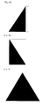
- FIGS. 4A to 4I are views showing massage operations of the vibrator which vibrates in different types according to output pulses output from the controller 140 to the drive 130. That is, the colored portions in the drawings are portions to which vibration of the vibrator is transmitted and the other portion is portion where the vibrator is stopped or not attached.
- FIG. 4A shows a case where relatively strong vibration continues same intensity for a preset time
- FIG. 4B shows relatively strong vibration of same intensity repeated every preset short time interval
- FIG. 4C shows relatively strong vibration of same intensity repeated for a preset time every short time interval.
- FIG. 4D shows visually weak vibration being gradually stronger for a preset time after starting
- FIG. 4E shows strong vibration being gradually weakening for a preset time after starting contrary to the case of FIG. 4D.
- FIG. 4F shows early weak vibration is gradually stronger to the peak and is gradually weakened again.
- FIGS. 4G to 4I is omitted.
- the battery 150 is installed on the supporting plate 160 and supplies electric power to the drive 130 and the controller 140 through the power connecting member 170.
- the battery 150 may be inserted into a battery hole 160b formed in the supporting plate 160 so as to reduce the overall thickness of the vibration module for skin massage 100 and its description is omitted because this is substantially identical to the insertion of the vibrator 120 into the vibrator holes 160a.
- the supporting plate 160 is provided to connect the printed circuit board 110 to the battery 150 integrally.
- the supporting plate 160 may be made of a flexible material such that flexibility of the vibration module for skin massage 100 can be guaranteed.
- the supporting plate 160 may be configured such that the battery 150 and the vibrator 120 are mounted at the ends in the major axis on an oval side of the supporting plate 160, respectively. Thus, devices are not mounted at the middle portion of the major axis and due to this the supporting plate 160 can exhibit elasticity and higher flexibility.
- the power connecting member 170 electrically connects the power terminals (not shown) of the battery 150 to the power terminals (not shown) of the drive 130 on the printed circuit board 110.
- the drive 130 receives electric power from the battery 150 through the power connecting member 170.
- the power terminals of the printed circuit board 110 may supply electric power to the controller 140 and in this case the printed circuit board 110 has circuit patterns connecting the power terminals to the drive 130 and the controller 140 in parallel.
- the insulator 180 is attached to a contact area between the power terminals of the battery 150 and the power connecting member 170. That is, the insulator 180 is attached to the battery 150 to interrupt the electrical connection between the power terminals of the battery 150 and the power connecting member 170 and the electrical connection between the power terminals of the battery 150 and the insulator 180 is made when the insulator 180 is separated from the battery 150.
- the insulator 180 is detachably attached to the battery 150 and controls the electrical connection between the power terminals of the battery 150 and the power connection member 170 through the attachment and detachment of the insulator 180 to control the electric power to be supplied from the battery 150 to the drive 130 or not.
- the insulator 180 can switch the electrical connection between the power terminals of the battery 150 and the power connecting member 170 and in this case the vibration module for skin massage 100 can spend the electric power of the battery 150 only by the switching function of the insulator 180 even without a separated switch. That is, omission of the switch allows reduction of volume of the vibration module for skin massage 100 and the electric power of the battery 150 may be spent only when the vibrator 120 is operated.
- the present invention is not limited thereto but the insulator 180 may be attached to and detached from power terminal regions of the battery 150 and may be modified under the conditions of applying electric power between the power terminals of the battery 150 and the power connecting member 170.
- FIG. 5 is a rear side view of the vibration module for skin massage according to the exemplary embodiment of the present invention in which the battery 150 and the vibrator 120 are inserted into the battery hole 160b and the vibrator holes 160a that are formed in the printed circuit board 110 and the supporting plate 160 and are fixed thereto.
- a buffering pad (not shown) may be attached to the rear side of the vibration module for skin massage 100 (the rear side of the supporting plate) and may prevent direct contact between the vibrator 120 and human skin.
- the buffering pad is omitted for the purpose of showing the battery hole 160b and the vibrator holes 160a and ones of sides of the battery 150 and the vibrator 120 which are inserted thereinto.
- the buffering pad may be made in various types such as nonwoven fabric or a sheet containing liquid material.
- the vibration module for skin massage 100 is configured such that the printed circuit board 110 on which the vibrator 120 and the drive 130 thereof and the controller 140 of the drive 130 are installed and the battery 150 are integrally attached to the flexible supporting plate 160, so that volume and thickness of the vibration module can be minimized and flexibility thereof can be guaranteed and vibration of the vibrator 120 is transmitted to the human skin through vibration of the whole vibration module so that the vibration can be transmitted to a relatively wide area on the human skin in comparison to the size of the vibrator.
- the power supply of the drive 130 driving the vibrator 120 includes a switch formed by thin terminals and a sheet insulator 180 so as to exclude a complex switch having a manipulator such as buttons so that the simple configuration and minimum volume thereof can be achieved and the electric power can be supplied to the drive 130 of the battery 150 by switching of an insulator 180 so that the electric power of the battery is consumed only when the vibrator 120 is driven.
- various vibrations of the vibrator 120 such as rubbing, picking, pressing, and knocking similar to massage carried out by human hands, in addition to the simple strong and weak vibrations, can be generated to improve skin massage effect by a controller 140 controlling the drive 130 of the vibrator 120 using pulse width modulation (PWM).
- PWM pulse width modulation
- the vibration module for skin massage secures flexibility thereof to be easily bent along the contour of user's face and to be closely attached to the face resulting in improving transmission of vibration to the skin.
- a vibration transmission region is relatively increased due to transmission of vibration through whole the vibration module and overall volume thereof is relatively reduced, resulting in improving mobility.
Landscapes
- Health & Medical Sciences (AREA)
- Epidemiology (AREA)
- Pain & Pain Management (AREA)
- Physical Education & Sports Medicine (AREA)
- Rehabilitation Therapy (AREA)
- Life Sciences & Earth Sciences (AREA)
- Animal Behavior & Ethology (AREA)
- General Health & Medical Sciences (AREA)
- Public Health (AREA)
- Veterinary Medicine (AREA)
- Dermatology (AREA)
- Percussion Or Vibration Massage (AREA)
Applications Claiming Priority (2)
| Application Number | Priority Date | Filing Date | Title |
|---|---|---|---|
| KR1020110069600A KR101254141B1 (ko) | 2011-07-13 | 2011-07-13 | 피부 마사지용 진동모듈 |
| PCT/KR2012/005573 WO2013009124A2 (ko) | 2011-07-13 | 2012-07-13 | 피부 마사지용 진동모듈 |
Publications (3)
| Publication Number | Publication Date |
|---|---|
| EP2719366A2 true EP2719366A2 (de) | 2014-04-16 |
| EP2719366A4 EP2719366A4 (de) | 2015-04-01 |
| EP2719366B1 EP2719366B1 (de) | 2016-11-02 |
Family
ID=47506736
Family Applications (1)
| Application Number | Title | Priority Date | Filing Date |
|---|---|---|---|
| EP12811226.5A Not-in-force EP2719366B1 (de) | 2011-07-13 | 2012-07-13 | Schwingungsmodul zum massieren der haut |
Country Status (6)
| Country | Link |
|---|---|
| EP (1) | EP2719366B1 (de) |
| JP (1) | JP5830607B2 (de) |
| KR (1) | KR101254141B1 (de) |
| CN (1) | CN103764090B (de) |
| TW (1) | TWI468156B (de) |
| WO (1) | WO2013009124A2 (de) |
Cited By (1)
| Publication number | Priority date | Publication date | Assignee | Title |
|---|---|---|---|---|
| CN114984439A (zh) * | 2022-06-21 | 2022-09-02 | 杭州昀鼎医疗科技有限公司 | 一种药物导入治疗贴及使用方法 |
Families Citing this family (6)
| Publication number | Priority date | Publication date | Assignee | Title |
|---|---|---|---|---|
| JP2739662B2 (ja) | 1991-11-18 | 1998-04-15 | 株式会社河合楽器製作所 | 電子楽器の簡易入力装置 |
| CN103598974A (zh) * | 2013-12-09 | 2014-02-26 | 苏州翰墨科技有限公司 | 脉动洁面仪 |
| KR101584507B1 (ko) * | 2014-05-22 | 2016-01-13 | (주)아모레퍼시픽 | 세안과 바디 및 마사지 모드 선택이 가능한 클렌징 장치 및 동작 제어방법 |
| US20180168913A1 (en) * | 2016-12-15 | 2018-06-21 | Filip Sedic | Personal massage apparatuses configured to generate stochastic resonance vibration and methods of use |
| KR102782459B1 (ko) * | 2019-05-16 | 2025-03-18 | 주식회사 엘지생활건강 | 피부미용기기 |
| KR102593809B1 (ko) * | 2022-12-22 | 2023-10-25 | 주식회사 엘에이치생활건강 | 마사지 장치 |
Family Cites Families (14)
| Publication number | Priority date | Publication date | Assignee | Title |
|---|---|---|---|---|
| JP2858715B2 (ja) * | 1992-07-23 | 1999-02-17 | 富士写真フイルム株式会社 | レンズ付きフイルムユニット |
| JP3448888B2 (ja) * | 1993-02-23 | 2003-09-22 | 松下電工株式会社 | 低周波治療器 |
| GB9408668D0 (en) * | 1994-04-30 | 1994-06-22 | Orthosonics Ltd | Untrasonic therapeutic system |
| JPH11213974A (ja) * | 1998-01-22 | 1999-08-06 | Sharp Corp | 電池絶縁装置 |
| KR100291011B1 (ko) * | 1998-09-16 | 2001-06-01 | 전병헌 | 미용마사지마스크 |
| JP2001276113A (ja) * | 2000-03-29 | 2001-10-09 | Toshihiro Kuribayashi | 眼性疲労及び視力低下防止器具 |
| KR200219490Y1 (ko) * | 2000-10-31 | 2001-04-02 | 이양희 | 피부부착용 진동 마사지기 |
| JP3089625U (ja) * | 2002-04-26 | 2002-10-31 | 林建豐 | 安全コンドーム |
| US7300409B2 (en) * | 2005-05-12 | 2007-11-27 | S.C. Johnson & Son, Inc. | Therapy patch |
| US20090259168A1 (en) * | 2005-10-16 | 2009-10-15 | Eran Izhak Prizant | Bandage |
| KR101031284B1 (ko) * | 2008-02-25 | 2011-04-29 | 양원동 | 기능성 목 밴드 |
| JP3156656U (ja) * | 2009-10-16 | 2010-01-14 | 弓長 薫 | 振動マッサージシップまたは貼付シートと、その製品構造 |
| KR101370678B1 (ko) * | 2009-11-19 | 2014-03-25 | 이용식 | 탈부착이 쉬운 마사지기를 구비한 화장품용기 |
| CN201906172U (zh) * | 2011-01-10 | 2011-07-27 | 深圳市瑞吉思科技有限公司 | 一种按摩美容棒 |
-
2011
- 2011-07-13 KR KR1020110069600A patent/KR101254141B1/ko not_active Expired - Fee Related
-
2012
- 2012-07-13 WO PCT/KR2012/005573 patent/WO2013009124A2/ko not_active Ceased
- 2012-07-13 CN CN201280033687.8A patent/CN103764090B/zh not_active Expired - Fee Related
- 2012-07-13 TW TW101125293A patent/TWI468156B/zh not_active IP Right Cessation
- 2012-07-13 JP JP2014520133A patent/JP5830607B2/ja not_active Expired - Fee Related
- 2012-07-13 EP EP12811226.5A patent/EP2719366B1/de not_active Not-in-force
Cited By (2)
| Publication number | Priority date | Publication date | Assignee | Title |
|---|---|---|---|---|
| CN114984439A (zh) * | 2022-06-21 | 2022-09-02 | 杭州昀鼎医疗科技有限公司 | 一种药物导入治疗贴及使用方法 |
| CN114984439B (zh) * | 2022-06-21 | 2023-09-15 | 杭州昀鼎医疗科技有限公司 | 一种药物导入治疗贴及使用方法 |
Also Published As
| Publication number | Publication date |
|---|---|
| JP5830607B2 (ja) | 2015-12-09 |
| HK1193019A1 (en) | 2014-09-12 |
| WO2013009124A2 (ko) | 2013-01-17 |
| TW201304761A (zh) | 2013-02-01 |
| CN103764090A (zh) | 2014-04-30 |
| WO2013009124A3 (ko) | 2013-04-04 |
| KR101254141B1 (ko) | 2013-04-18 |
| JP2014530641A (ja) | 2014-11-20 |
| CN103764090B (zh) | 2015-09-30 |
| EP2719366B1 (de) | 2016-11-02 |
| KR20130008912A (ko) | 2013-01-23 |
| EP2719366A4 (de) | 2015-04-01 |
| TWI468156B (zh) | 2015-01-11 |
Similar Documents
| Publication | Publication Date | Title |
|---|---|---|
| US20140163438A1 (en) | Vibration module for massaging skin | |
| EP2719366B1 (de) | Schwingungsmodul zum massieren der haut | |
| US10111805B2 (en) | Facial massager | |
| CN104274903B (zh) | 美容器 | |
| JP2002306604A (ja) | リラクゼーション装置 | |
| KR200185058Y1 (ko) | 안면 마사지기 | |
| JP4592329B2 (ja) | イオン導入器 | |
| US9962315B2 (en) | Electric module for stimulating skin | |
| HK1193019B (en) | Vibration module for massaging skin | |
| JP2002000684A (ja) | 超音波美容器 | |
| HK1197144A2 (zh) | 面部按摩器 | |
| JP2010148979A (ja) | イオン導入器 |
Legal Events
| Date | Code | Title | Description |
|---|---|---|---|
| PUAI | Public reference made under article 153(3) epc to a published international application that has entered the european phase |
Free format text: ORIGINAL CODE: 0009012 |
|
| 17P | Request for examination filed |
Effective date: 20140113 |
|
| AK | Designated contracting states |
Kind code of ref document: A2 Designated state(s): AL AT BE BG CH CY CZ DE DK EE ES FI FR GB GR HR HU IE IS IT LI LT LU LV MC MK MT NL NO PL PT RO RS SE SI SK SM TR |
|
| DAX | Request for extension of the european patent (deleted) | ||
| A4 | Supplementary search report drawn up and despatched |
Effective date: 20150227 |
|
| RIC1 | Information provided on ipc code assigned before grant |
Ipc: A61H 7/00 20060101ALI20150223BHEP Ipc: A61H 23/02 20060101AFI20150223BHEP |
|
| GRAP | Despatch of communication of intention to grant a patent |
Free format text: ORIGINAL CODE: EPIDOSNIGR1 |
|
| INTG | Intention to grant announced |
Effective date: 20160525 |
|
| RAP1 | Party data changed (applicant data changed or rights of an application transferred) |
Owner name: AMOREPACIFIC CORPORATION Owner name: SENTRONIX CO., LTD. |
|
| GRAS | Grant fee paid |
Free format text: ORIGINAL CODE: EPIDOSNIGR3 |
|
| GRAA | (expected) grant |
Free format text: ORIGINAL CODE: 0009210 |
|
| AK | Designated contracting states |
Kind code of ref document: B1 Designated state(s): AL AT BE BG CH CY CZ DE DK EE ES FI FR GB GR HR HU IE IS IT LI LT LU LV MC MK MT NL NO PL PT RO RS SE SI SK SM TR |
|
| REG | Reference to a national code |
Ref country code: GB Ref legal event code: FG4D |
|
| REG | Reference to a national code |
Ref country code: AT Ref legal event code: REF Ref document number: 841060 Country of ref document: AT Kind code of ref document: T Effective date: 20161115 Ref country code: CH Ref legal event code: EP |
|
| REG | Reference to a national code |
Ref country code: IE Ref legal event code: FG4D |
|
| REG | Reference to a national code |
Ref country code: DE Ref legal event code: R096 Ref document number: 602012024957 Country of ref document: DE |
|
| PG25 | Lapsed in a contracting state [announced via postgrant information from national office to epo] |
Ref country code: LV Free format text: LAPSE BECAUSE OF FAILURE TO SUBMIT A TRANSLATION OF THE DESCRIPTION OR TO PAY THE FEE WITHIN THE PRESCRIBED TIME-LIMIT Effective date: 20161102 |
|
| REG | Reference to a national code |
Ref country code: NL Ref legal event code: MP Effective date: 20161102 |
|
| REG | Reference to a national code |
Ref country code: LT Ref legal event code: MG4D |
|
| REG | Reference to a national code |
Ref country code: AT Ref legal event code: MK05 Ref document number: 841060 Country of ref document: AT Kind code of ref document: T Effective date: 20161102 |
|
| PG25 | Lapsed in a contracting state [announced via postgrant information from national office to epo] |
Ref country code: NO Free format text: LAPSE BECAUSE OF FAILURE TO SUBMIT A TRANSLATION OF THE DESCRIPTION OR TO PAY THE FEE WITHIN THE PRESCRIBED TIME-LIMIT Effective date: 20170202 Ref country code: GR Free format text: LAPSE BECAUSE OF FAILURE TO SUBMIT A TRANSLATION OF THE DESCRIPTION OR TO PAY THE FEE WITHIN THE PRESCRIBED TIME-LIMIT Effective date: 20170203 Ref country code: LT Free format text: LAPSE BECAUSE OF FAILURE TO SUBMIT A TRANSLATION OF THE DESCRIPTION OR TO PAY THE FEE WITHIN THE PRESCRIBED TIME-LIMIT Effective date: 20161102 Ref country code: SE Free format text: LAPSE BECAUSE OF FAILURE TO SUBMIT A TRANSLATION OF THE DESCRIPTION OR TO PAY THE FEE WITHIN THE PRESCRIBED TIME-LIMIT Effective date: 20161102 Ref country code: NL Free format text: LAPSE BECAUSE OF FAILURE TO SUBMIT A TRANSLATION OF THE DESCRIPTION OR TO PAY THE FEE WITHIN THE PRESCRIBED TIME-LIMIT Effective date: 20161102 |
|
| PG25 | Lapsed in a contracting state [announced via postgrant information from national office to epo] |
Ref country code: RS Free format text: LAPSE BECAUSE OF FAILURE TO SUBMIT A TRANSLATION OF THE DESCRIPTION OR TO PAY THE FEE WITHIN THE PRESCRIBED TIME-LIMIT Effective date: 20161102 Ref country code: PL Free format text: LAPSE BECAUSE OF FAILURE TO SUBMIT A TRANSLATION OF THE DESCRIPTION OR TO PAY THE FEE WITHIN THE PRESCRIBED TIME-LIMIT Effective date: 20161102 Ref country code: FI Free format text: LAPSE BECAUSE OF FAILURE TO SUBMIT A TRANSLATION OF THE DESCRIPTION OR TO PAY THE FEE WITHIN THE PRESCRIBED TIME-LIMIT Effective date: 20161102 Ref country code: ES Free format text: LAPSE BECAUSE OF FAILURE TO SUBMIT A TRANSLATION OF THE DESCRIPTION OR TO PAY THE FEE WITHIN THE PRESCRIBED TIME-LIMIT Effective date: 20161102 Ref country code: AT Free format text: LAPSE BECAUSE OF FAILURE TO SUBMIT A TRANSLATION OF THE DESCRIPTION OR TO PAY THE FEE WITHIN THE PRESCRIBED TIME-LIMIT Effective date: 20161102 Ref country code: PT Free format text: LAPSE BECAUSE OF FAILURE TO SUBMIT A TRANSLATION OF THE DESCRIPTION OR TO PAY THE FEE WITHIN THE PRESCRIBED TIME-LIMIT Effective date: 20170302 Ref country code: HR Free format text: LAPSE BECAUSE OF FAILURE TO SUBMIT A TRANSLATION OF THE DESCRIPTION OR TO PAY THE FEE WITHIN THE PRESCRIBED TIME-LIMIT Effective date: 20161102 Ref country code: IS Free format text: LAPSE BECAUSE OF FAILURE TO SUBMIT A TRANSLATION OF THE DESCRIPTION OR TO PAY THE FEE WITHIN THE PRESCRIBED TIME-LIMIT Effective date: 20170302 |
|
| REG | Reference to a national code |
Ref country code: FR Ref legal event code: PLFP Year of fee payment: 6 |
|
| PG25 | Lapsed in a contracting state [announced via postgrant information from national office to epo] |
Ref country code: RO Free format text: LAPSE BECAUSE OF FAILURE TO SUBMIT A TRANSLATION OF THE DESCRIPTION OR TO PAY THE FEE WITHIN THE PRESCRIBED TIME-LIMIT Effective date: 20161102 Ref country code: SK Free format text: LAPSE BECAUSE OF FAILURE TO SUBMIT A TRANSLATION OF THE DESCRIPTION OR TO PAY THE FEE WITHIN THE PRESCRIBED TIME-LIMIT Effective date: 20161102 Ref country code: EE Free format text: LAPSE BECAUSE OF FAILURE TO SUBMIT A TRANSLATION OF THE DESCRIPTION OR TO PAY THE FEE WITHIN THE PRESCRIBED TIME-LIMIT Effective date: 20161102 Ref country code: CZ Free format text: LAPSE BECAUSE OF FAILURE TO SUBMIT A TRANSLATION OF THE DESCRIPTION OR TO PAY THE FEE WITHIN THE PRESCRIBED TIME-LIMIT Effective date: 20161102 Ref country code: DK Free format text: LAPSE BECAUSE OF FAILURE TO SUBMIT A TRANSLATION OF THE DESCRIPTION OR TO PAY THE FEE WITHIN THE PRESCRIBED TIME-LIMIT Effective date: 20161102 |
|
| REG | Reference to a national code |
Ref country code: DE Ref legal event code: R097 Ref document number: 602012024957 Country of ref document: DE |
|
| PG25 | Lapsed in a contracting state [announced via postgrant information from national office to epo] |
Ref country code: IT Free format text: LAPSE BECAUSE OF FAILURE TO SUBMIT A TRANSLATION OF THE DESCRIPTION OR TO PAY THE FEE WITHIN THE PRESCRIBED TIME-LIMIT Effective date: 20161102 Ref country code: BE Free format text: LAPSE BECAUSE OF FAILURE TO SUBMIT A TRANSLATION OF THE DESCRIPTION OR TO PAY THE FEE WITHIN THE PRESCRIBED TIME-LIMIT Effective date: 20161102 Ref country code: BG Free format text: LAPSE BECAUSE OF FAILURE TO SUBMIT A TRANSLATION OF THE DESCRIPTION OR TO PAY THE FEE WITHIN THE PRESCRIBED TIME-LIMIT Effective date: 20170202 Ref country code: SM Free format text: LAPSE BECAUSE OF FAILURE TO SUBMIT A TRANSLATION OF THE DESCRIPTION OR TO PAY THE FEE WITHIN THE PRESCRIBED TIME-LIMIT Effective date: 20161102 |
|
| PLBE | No opposition filed within time limit |
Free format text: ORIGINAL CODE: 0009261 |
|
| STAA | Information on the status of an ep patent application or granted ep patent |
Free format text: STATUS: NO OPPOSITION FILED WITHIN TIME LIMIT |
|
| 26N | No opposition filed |
Effective date: 20170803 |
|
| PG25 | Lapsed in a contracting state [announced via postgrant information from national office to epo] |
Ref country code: SI Free format text: LAPSE BECAUSE OF FAILURE TO SUBMIT A TRANSLATION OF THE DESCRIPTION OR TO PAY THE FEE WITHIN THE PRESCRIBED TIME-LIMIT Effective date: 20161102 |
|
| REG | Reference to a national code |
Ref country code: DE Ref legal event code: R119 Ref document number: 602012024957 Country of ref document: DE |
|
| REG | Reference to a national code |
Ref country code: CH Ref legal event code: PL |
|
| GBPC | Gb: european patent ceased through non-payment of renewal fee |
Effective date: 20170713 |
|
| REG | Reference to a national code |
Ref country code: IE Ref legal event code: MM4A |
|
| PG25 | Lapsed in a contracting state [announced via postgrant information from national office to epo] |
Ref country code: GB Free format text: LAPSE BECAUSE OF NON-PAYMENT OF DUE FEES Effective date: 20170713 Ref country code: DE Free format text: LAPSE BECAUSE OF NON-PAYMENT OF DUE FEES Effective date: 20180201 Ref country code: IE Free format text: LAPSE BECAUSE OF NON-PAYMENT OF DUE FEES Effective date: 20170713 Ref country code: CH Free format text: LAPSE BECAUSE OF NON-PAYMENT OF DUE FEES Effective date: 20170731 Ref country code: LI Free format text: LAPSE BECAUSE OF NON-PAYMENT OF DUE FEES Effective date: 20170731 |
|
| REG | Reference to a national code |
Ref country code: FR Ref legal event code: PLFP Year of fee payment: 7 |
|
| PG25 | Lapsed in a contracting state [announced via postgrant information from national office to epo] |
Ref country code: LU Free format text: LAPSE BECAUSE OF NON-PAYMENT OF DUE FEES Effective date: 20170713 |
|
| PG25 | Lapsed in a contracting state [announced via postgrant information from national office to epo] |
Ref country code: MT Free format text: LAPSE BECAUSE OF NON-PAYMENT OF DUE FEES Effective date: 20170713 |
|
| PG25 | Lapsed in a contracting state [announced via postgrant information from national office to epo] |
Ref country code: HU Free format text: LAPSE BECAUSE OF FAILURE TO SUBMIT A TRANSLATION OF THE DESCRIPTION OR TO PAY THE FEE WITHIN THE PRESCRIBED TIME-LIMIT; INVALID AB INITIO Effective date: 20120713 Ref country code: MC Free format text: LAPSE BECAUSE OF FAILURE TO SUBMIT A TRANSLATION OF THE DESCRIPTION OR TO PAY THE FEE WITHIN THE PRESCRIBED TIME-LIMIT Effective date: 20161102 |
|
| PG25 | Lapsed in a contracting state [announced via postgrant information from national office to epo] |
Ref country code: CY Free format text: LAPSE BECAUSE OF NON-PAYMENT OF DUE FEES Effective date: 20161102 |
|
| PG25 | Lapsed in a contracting state [announced via postgrant information from national office to epo] |
Ref country code: MK Free format text: LAPSE BECAUSE OF FAILURE TO SUBMIT A TRANSLATION OF THE DESCRIPTION OR TO PAY THE FEE WITHIN THE PRESCRIBED TIME-LIMIT Effective date: 20161102 |
|
| PG25 | Lapsed in a contracting state [announced via postgrant information from national office to epo] |
Ref country code: TR Free format text: LAPSE BECAUSE OF FAILURE TO SUBMIT A TRANSLATION OF THE DESCRIPTION OR TO PAY THE FEE WITHIN THE PRESCRIBED TIME-LIMIT Effective date: 20161102 |
|
| PG25 | Lapsed in a contracting state [announced via postgrant information from national office to epo] |
Ref country code: AL Free format text: LAPSE BECAUSE OF FAILURE TO SUBMIT A TRANSLATION OF THE DESCRIPTION OR TO PAY THE FEE WITHIN THE PRESCRIBED TIME-LIMIT Effective date: 20161102 |
|
| PGFP | Annual fee paid to national office [announced via postgrant information from national office to epo] |
Ref country code: FR Payment date: 20210625 Year of fee payment: 10 |
|
| PG25 | Lapsed in a contracting state [announced via postgrant information from national office to epo] |
Ref country code: FR Free format text: LAPSE BECAUSE OF NON-PAYMENT OF DUE FEES Effective date: 20220731 |