EP2716980A2 - Pipe manifold system - Google Patents
Pipe manifold system Download PDFInfo
- Publication number
- EP2716980A2 EP2716980A2 EP13187146.9A EP13187146A EP2716980A2 EP 2716980 A2 EP2716980 A2 EP 2716980A2 EP 13187146 A EP13187146 A EP 13187146A EP 2716980 A2 EP2716980 A2 EP 2716980A2
- Authority
- EP
- European Patent Office
- Prior art keywords
- pipe
- main
- main pipe
- tube
- functional unit
- Prior art date
- Legal status (The legal status is an assumption and is not a legal conclusion. Google has not performed a legal analysis and makes no representation as to the accuracy of the status listed.)
- Granted
Links
- 238000005304 joining Methods 0.000 claims abstract description 13
- 238000004519 manufacturing process Methods 0.000 claims abstract description 11
- 238000009826 distribution Methods 0.000 claims description 17
- 239000012530 fluid Substances 0.000 claims description 14
- 238000000034 method Methods 0.000 claims description 12
- 239000011324 bead Substances 0.000 claims description 10
- 230000001105 regulatory effect Effects 0.000 claims description 6
- XLYOFNOQVPJJNP-UHFFFAOYSA-N water Substances O XLYOFNOQVPJJNP-UHFFFAOYSA-N 0.000 claims description 4
- 238000009423 ventilation Methods 0.000 abstract 1
- 238000010438 heat treatment Methods 0.000 description 12
- 238000013022 venting Methods 0.000 description 9
- 229910000679 solder Inorganic materials 0.000 description 7
- 238000003466 welding Methods 0.000 description 7
- 238000007789 sealing Methods 0.000 description 5
- 238000001816 cooling Methods 0.000 description 4
- 238000007373 indentation Methods 0.000 description 4
- 239000000463 material Substances 0.000 description 4
- 230000000630 rising effect Effects 0.000 description 4
- 238000009434 installation Methods 0.000 description 3
- 239000000565 sealant Substances 0.000 description 3
- 244000089486 Phragmites australis subsp australis Species 0.000 description 2
- 238000002788 crimping Methods 0.000 description 2
- 230000012447 hatching Effects 0.000 description 2
- 230000000007 visual effect Effects 0.000 description 2
- 239000000853 adhesive Substances 0.000 description 1
- 238000004026 adhesive bonding Methods 0.000 description 1
- 230000001070 adhesive effect Effects 0.000 description 1
- 229910045601 alloy Inorganic materials 0.000 description 1
- 239000000956 alloy Substances 0.000 description 1
- POIUWJQBRNEFGX-XAMSXPGMSA-N cathelicidin Chemical compound C([C@@H](C(=O)N[C@@H](CCCNC(N)=N)C(=O)N[C@@H](CCCCN)C(=O)N[C@@H](CO)C(=O)N[C@@H](CCCCN)C(=O)N[C@@H](CCC(O)=O)C(=O)N[C@@H](CCCCN)C(=O)N[C@@H]([C@@H](C)CC)C(=O)NCC(=O)N[C@@H](CCCCN)C(=O)N[C@@H](CCC(O)=O)C(=O)N[C@@H](CC=1C=CC=CC=1)C(=O)N[C@@H](CCCCN)C(=O)N[C@@H](CCCNC(N)=N)C(=O)N[C@@H]([C@@H](C)CC)C(=O)N[C@@H](C(C)C)C(=O)N[C@@H](CCC(N)=O)C(=O)N[C@@H](CCCNC(N)=N)C(=O)N[C@@H]([C@@H](C)CC)C(=O)N[C@@H](CCCCN)C(=O)N[C@@H](CC(O)=O)C(=O)N[C@@H](CC=1C=CC=CC=1)C(=O)N[C@@H](CC(C)C)C(=O)N[C@@H](CCCNC(N)=N)C(=O)N[C@@H](CC(N)=O)C(=O)N[C@@H](CC(C)C)C(=O)N[C@@H](C(C)C)C(=O)N1[C@@H](CCC1)C(=O)N[C@@H](CCCNC(N)=N)C(=O)N[C@@H]([C@@H](C)O)C(=O)N[C@@H](CCC(O)=O)C(=O)N[C@@H](CO)C(O)=O)NC(=O)[C@H](CC=1C=CC=CC=1)NC(=O)[C@H](CC(O)=O)NC(=O)CNC(=O)[C@H](CC(C)C)NC(=O)[C@@H](N)CC(C)C)C1=CC=CC=C1 POIUWJQBRNEFGX-XAMSXPGMSA-N 0.000 description 1
- 238000004140 cleaning Methods 0.000 description 1
- 230000006835 compression Effects 0.000 description 1
- 238000007906 compression Methods 0.000 description 1
- 230000001276 controlling effect Effects 0.000 description 1
- 230000007797 corrosion Effects 0.000 description 1
- 238000005260 corrosion Methods 0.000 description 1
- 230000001627 detrimental effect Effects 0.000 description 1
- 239000013013 elastic material Substances 0.000 description 1
- 239000003792 electrolyte Substances 0.000 description 1
- 230000004927 fusion Effects 0.000 description 1
- 239000003292 glue Substances 0.000 description 1
- 230000003993 interaction Effects 0.000 description 1
- 230000007257 malfunction Effects 0.000 description 1
- 229910052751 metal Inorganic materials 0.000 description 1
- 239000002184 metal Substances 0.000 description 1
- 150000002739 metals Chemical class 0.000 description 1
- 238000012544 monitoring process Methods 0.000 description 1
- 239000003507 refrigerant Substances 0.000 description 1
- 238000005476 soldering Methods 0.000 description 1
Images


Classifications
-
- F—MECHANICAL ENGINEERING; LIGHTING; HEATING; WEAPONS; BLASTING
- F24—HEATING; RANGES; VENTILATING
- F24D—DOMESTIC- OR SPACE-HEATING SYSTEMS, e.g. CENTRAL HEATING SYSTEMS; DOMESTIC HOT-WATER SUPPLY SYSTEMS; ELEMENTS OR COMPONENTS THEREFOR
- F24D3/00—Hot-water central heating systems
- F24D3/10—Feed-line arrangements, e.g. providing for heat-accumulator tanks, expansion tanks ; Hydraulic components of a central heating system
- F24D3/1058—Feed-line arrangements, e.g. providing for heat-accumulator tanks, expansion tanks ; Hydraulic components of a central heating system disposition of pipes and pipe connections
- F24D3/1066—Distributors for heating liquids
-
- F—MECHANICAL ENGINEERING; LIGHTING; HEATING; WEAPONS; BLASTING
- F16—ENGINEERING ELEMENTS AND UNITS; GENERAL MEASURES FOR PRODUCING AND MAINTAINING EFFECTIVE FUNCTIONING OF MACHINES OR INSTALLATIONS; THERMAL INSULATION IN GENERAL
- F16L—PIPES; JOINTS OR FITTINGS FOR PIPES; SUPPORTS FOR PIPES, CABLES OR PROTECTIVE TUBING; MEANS FOR THERMAL INSULATION IN GENERAL
- F16L41/00—Branching pipes; Joining pipes to walls
- F16L41/02—Branch units, e.g. made in one piece, welded, riveted
- F16L41/03—Branch units, e.g. made in one piece, welded, riveted comprising junction pieces for four or more pipe members
-
- F—MECHANICAL ENGINEERING; LIGHTING; HEATING; WEAPONS; BLASTING
- F24—HEATING; RANGES; VENTILATING
- F24D—DOMESTIC- OR SPACE-HEATING SYSTEMS, e.g. CENTRAL HEATING SYSTEMS; DOMESTIC HOT-WATER SUPPLY SYSTEMS; ELEMENTS OR COMPONENTS THEREFOR
- F24D2220/00—Components of central heating installations excluding heat sources
- F24D2220/02—Fluid distribution means
Definitions
- the invention relates to a pipe distributor system according to the preamble of claim 1 and to a pipe distributor system according to the preamble of claim 2. Furthermore, the invention relates to a method for producing a thread on parts of the pipe distributor system according to the preamble of claim 12.
- Piping systems are known from the prior art, in which several outlets branch off from a main pipe. These pipe distribution systems are often called in professional circles also Banknikverteiler.
- a heating circuit distributor is used to connect radiators or to connect floor or wall heating systems to one or more main lines. These piping systems generally have a main pipe for the feed and a main pipe for the return. For distribution, monitoring, control and regulation of the partial flows (partial fluid flows), connection elements, flow indicators, valves and thermostats are assigned to the outlets of the main pipe. At the respective connection elements, the respective continuing or returning line of the relevant sub-heating circuit or sub-cooling circuit is connected.
- the heating circuit distributor is used for the distribution of the mass flow from the main / riser from the boiler used for the individual radiators / radiators.
- the central distribution enables a star-shaped connection of the radiators.
- a modified heating circuit distributor is also used for the distribution and balancing (DIN EN 1264-4 "Hydraulic balancing") of the mass flow of individual low-temperature heating circuits in floor or wall heating systems.
- These connection elements, flow indicators, valves and thermostats are referred to below as a functional unit.
- These functional units act, for example, in such a way that, for example, a part of a partial element of the valve - for example a valve plate - acts on a surface of a disposed at the relevant outlet further sub-element of the valve, whereby the flow of the fluid (usually water) influenced or measured becomes.
- the corresponding surface is effectively a valve seat.
- the valve seat or the partial element with the valve seat is accommodated in a connection element arranged at the outlet in question or together with the connection element forms a partial element.
- connection elements and the flow indicators, valves and thermostats are screwed into the main pipe and sealed or glued or soldered, such as in a hot water distributor after the DE 10 2007 010 116 A1 .
- necklaces In order to be able to screw in, glue or solder the functional units, so-called necklaces must first be attached to the main pipe, which may be directed outwards or inwards at the outlets that partially open the main pipe, and it must also, if a screw connection is selected for the assembly, threads are cut or rolled in or on these necklaces.
- the relevant connection elements usually sections of their housing must also be threaded and the outlet must also be provided with a seal, usually an O-ring or sealant or adhesive, so that overall high production costs and assembly costs arise.
- the relevant contact surfaces are to be prepared on the part of the functional unit and the main pipe according to the selected joining method, which requires at least a careful cleaning and thus a further time in the assembly.
- this object is achieved with a manifold system with the features of claim 1 and with a manifold system with the features of claim 2; Claims 2 to 11 disclose design variants of the manifold system.
- a method with provided the features of claim 12; Claims 13 to 15 disclose design variants of the method.
- the invention relates to a piping system for a fluid flow with at least one central main pipe and at least one functional unit for emptying and filling the system or for shutting off, opening or regulating a partial volume flow, wherein the functional unit consists of at least a first and a second sub-element and the Main axis of the main pipe are arranged substantially at right angles and aligned with each other, and wherein the main pipe in the region of the functional units has widenings with at least two mutually parallel joining surfaces.
- the functional unit consists of at least a first and a second sub-element and the Main axis of the main pipe are arranged substantially at right angles and aligned with each other, and wherein the main pipe in the region of the functional units has widenings with at least two mutually parallel joining surfaces.
- An alternative of the invention is a pipe distributor system for a fluid flow with at least one central main pipe and at least one functional unit for draining and filling the system or for shutting off, opening or regulating a partial volume flow, wherein the functional unit consists of at least a first and a second sub-element and to the main axis of the main pipe substantially the main pipe in the region of the functional units has widenings with at least two joining surfaces arranged parallel to one another, in which the main pipe is substantially flat and designed at least in the joining region of the second partial elements such that no necking is formed there.
- a manifold system for a fluid flow ie, that in the said joining region on the main pipe no outlets are present, the flow behavior of the provided in the main pipe and from this through the outlets into partial streams distributed fluid (heat or refrigerant ) less disturbed, so that in particular the regulation of the mass flows (hydraulic balancing) trouble-free, especially sensitive, can be done.
- the outer dimensions of a pipe distribution system can be kept smaller due to the absence of the necking, in particular of necklaces projecting outwards on the main pipe.
- Another advantage is that unintentional and unauthorized loosening of components of the manifold system is prevented by the fixed arrangement of at least partial elements of the functional units on the main pipe.
- the manufacturing and assembly costs can be reduced, in particular the installation costs on site during installation of the pipe distribution systems in the heating system or cooling system, in particular a building, for example, a floor heating or wall heating.
- the assembly is on site simplified, which is particularly advantageous for home improvement but also installation companies.
- At least one subelement of the functional units is fused to the main pipe (1), preferably by welding, in particular by laser welding.
- the second sub-element is a special connection element for a partial volume flow and the associated line.
- the special versions are mentioned later in the description.
- the functional unit in conjunction with the second sub-element - ie the connection element - a valve or a flow indicator or a thermostat.
- At least one housing part of a functional unit is captively and tightly connected to the main pipe, preferably a first sub-element, in particular the sub-element of a functional unit having actuators.
- the actuators are the spindle with a valve disk or, in the case of a flow indicator, the measuring spindle or a regulating sleeve.
- the pipe distribution system consists of at least one main pipe for an inlet and at least one main pipe for the return.
- the fluid is usually water.
- the functional unit is formed in the form of a valve with a valve seat
- this valve seat is formed by at least one region of the main pipe.
- the valve seat is raised relative to the inner surface of the main pipe and directed towards the longitudinal axis of the main pipe.
- the valve seat is an annular wall / bead, wherein the wall is arranged in the region of the edge of the respectively provided opening of the main pipe.
- the bead is formed at the edge region of the respective opening, preferably by deformation.
- the invention also relates to a method for producing a thread for a manifold system, in particular for a manifold according to one of the device claims, in which according to the invention, a pipe end, preferably the tube end of a connection element, is flanged so that the flanged portion of the tube like a second, outer layer on the surface of the output tube comes to rest and in or on this outer layer is threaded.
- a thread is produced at least at one end of the main pipe according to the aforementioned method steps.
- the thread is rolled into the surface.
- the inventor has recognized that, despite the small distances between the main pipe and the outlets and between the outlets, it is possible to fuse them with the main pipe by means of a thermal bonding method, without causing damage to individual components of the components by heat. As a result, the outlets are captive and at the same time tight. This has the further advantage that with one operation the outlets or the components of the system can be mounted. The manufacturing costs and assembly costs are lower. An exchange of functional units and their components or outlets against those with lower quality or lower performance or lower life is no longer possible after the production of a manifold system according to the invention. Warranties on a manifold system and claims arising from these warranties are much easier to control in a piping system according to the invention and unauthorized persons are more clearly detectable than can be done with prior art piping systems.
- FIG. 1a In the FIG. 1a is a main pipe 1 to see, which has a plurality of valves 3 for controlling a fluid at the top.
- ports 15 At the bottom of the main pipe 1 ports 15 are arranged, which are axially opposite the valves 3.
- the main pipe 1 can be connected by means of a union nut 13 with other - not shown here pipes.
- the end of the main pipe 1 is provided with a sealing plug 8.
- An emptying element 6 for filling or emptying the manifold system is mounted on the underside of the main pipe 1. If the system is filled, a stopcock, not shown here, is closed at the emptying element 6.
- a closure cap 17 prevents fouling of the connection thread on the Emptying element 6.
- a venting element 7 Above the emptying element 6, a venting element 7 is arranged, which is often designed as fully automatic venting.
- the main tubes 1 are provided with widenings, so that the per se round main tubes 1 above and below each have a plate-shaped mounting surface - a joining surface for functional units - receive.
- the widenings are the regions of the original main tube 1 which, at least in the median plane of the widening transverse to the main axis 20, finally represent a substantially square cross section of this tube, see in FIGS FIGS. 2a and 2b , Since the expansions are not clearly represented by reference numerals, a reference number has been omitted here.
- connection elements 15 and 18 are fused to the main pipe 1.
- the first, arranged above the main pipe 1 sub-elements of the functional units are fused to the main pipe 1, preferably portions of the housing.
- heat-sensitive components (screw caps, collars, etc.) of the first (upper) sub-elements are attached to the functional unit only after merging with the main pipe 1.
- the fusion can be done by means of different welding techniques. This requires that both the main pipe 1 and the sub-elements one have similar material.
- a preferred welding technique is laser welding.
- FIGS. 2a and 2b you can see both the expanded, quasi-square and at the same time the original circular cross-section of the main pipe 1.
- the light edges 21 By the expansion of the pipe cross-section at this point, the light edges 21.
- a valve plate 10 of the valve 3 is at a defined distance from an opening 12 of the main pipe 1 and thus generates a defined flow of the partial volume flow of the fluid.
- the connection 19 is not connected by means of a necking - similar to the upper part of the valve element 3 - with the main pipe 1, but is welded from the outside to the surface of the main pipe 1 by means of a weld 9.
- valve element 3 is screwed by means of a thread in the main pipe 1 here.
- this upper subelement can also be fused to the main tube 1.
- all easily detachable parts must be heat resistant. That is, the valve cap 16, which is usually made of plastic, may be attached only after cooling of the sub-element.
- FIG. 2a is also a special embodiment of the thread at the terminal 19 to see.
- the pipe material of the connection is also thin-walled, like the main pipe 1, in order to save material and weight, the pipe end was flanged in a previous operation in such a way that the material became double-layered there and a thread was arranged there.
- the outer layer is weakened by the thread, however, this outer layer is supported by the inner layer.
- WO2011 / 11035 A1 in which a threaded ring is pushed onto the pipe end and the threaded ring then holds more or less by a widening of the pipe end, no additional threaded ring is required in the inventive solution.
- the thread is non-rotatably mounted on the pipe, which reduces manufacturing costs and reliability of a connection is ensured to a greater extent.
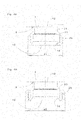
- FIGS. 3a and 3b For example, a drainage element 6 and a venting element 7 can be seen in combination with the already explained valves 3 and flow indicators 4.
- valves 3 and flow indicators 4 without thread, but by means of welding 9 to the main pipe 1 are connected.
- the venting elements 7 - preferably designed as an automatic venting - and the discharge elements 6 are welded to the main pipe 1.
- non-heat-resistant parts must not be attached to the functional units 3, 4, 6 and 7 until after welding and subsequent cooling.
- FIGS. 4a and 4b should be discussed in detail on the thread produced according to the invention.
- a connection 19 can be seen here in its final assembly state on a main pipe 1.
- the lower end of the terminal 19 has been previously widened in a separate machine first. After that became a part of Flared tube so that an outer layer 22 comes to rest on an inner layer 23 of the tube 19. If then in the outer layer 22 a thread is introduced (cut or rolled), although the outer layer 22 is weakened, but in turn supported by the inner layer 23. At the inner layer 23, a euro cone 14 is arranged on the inside in the end.
- the pipe is not originally widened, but the portion 24, which later is closer to the main pipe 1, is compressed in its diameter and / or stretched in length. This is indicated in the figures by the different wall thicknesses.
- FIGS. 5a to 5c becomes an opening 12 - as it already in the FIGS. 2a . 3a . 4a and 4b can be seen - shown in a particular embodiment.
- an opening 12 has been punched into the bottom of the wall of the main pipe 1, but at the edge of the opening 12 has a somewhat raised wall 30 (bead) for the valve seat 11 has been formed and at the same time a conical compression or extension of the edge of the Opening 12 takes place.
- the opening 12 and the valve seat 11 are flat. You can not from a necking of the main pipe.
- valve seat 11 rises with a height 30h less than the wall thickness 1h of the main pipe 1 on the inner surface 1b of the main pipe 1 addition.
- the design of the valve in the FIGS. 5a to 5c does not need to be explained in detail, because - apart from the valve seat 11 - corresponds to the prior art.
- the wall / bead 30 is provided annularly at the edge of the respective opening 12, preferably the edge itself is formed as a wall / bead 30, preferably by deformation.
- FIGS. 5d to 5g Details of the Wall / Bead 30 are in the FIGS. 5d to 5g shown schematically.
- the FIG. 5d is a copy of FIG. 5c in which the area / the detail E is marked with a dot-dashed circle, which in the FIGS. 5e to 5g is shown enlarged, so that details of the bead-shaped wall 30 which annularly surrounds the opening 20, and the valve disk 10 can be seen.
- FIG. 5e is this detail E from the FIG. 5d so enlarged shown that clearly the system of the valve disc 10 is seen on the wall 30.
- the valve disk 10 is pressed against the wall 30 such that a concave indentation, a recess, is formed in the valve disk.
- the valve disk 10 consists of a substantially elastic material, so that the concave indentation disappears upon release of the valve disk from the wall.
- the special / invention of this valve seat in the form of a bead-like wall 30 is the arrangement of a central region 30b, which seen in cross section, see FIG. 5g is curvilinear, with sideways sloping flanks 30c and 30d, respectively.
- the flank 30c is rising from the inner surface 1b of the main pipe 1 and the flank 30d drops toward the opening 12.
- the contour of the rising flank 30c and the falling flank 30d may be rectilinear or curvilinear, as seen in cross-section, or a combination of a rectilinear and a curvilinear section.
- FIG. 5g is the contact between the wall 30 and the valve plate 10 as shown in the FIG. 5e shown again, but here, in the FIG.
- valve seat according to the invention virtually three sealing surfaces are formed, so that a reliable sealing, even at high pressures in the pipe distribution system, in particular in the main pipe 1, is ensured.
- FIG. 6 is essentially a combination of FIGS. 3a and 3b , only with the peculiarity that here the opening 12 is designed with the valve seat 11 in such a way as in the FIGS. 5a to 5c is shown.
- FIG. 7 is an alternative to the valve seat 11 of FIGS. 5a to 5c shown.
- the valve is closed instead of a flat valve disc with an O-ring 22, the valve seat is seated on the cone of the opening 12.
- the invention is not limited to the aforementioned and described embodiments / variants.
- the invention also encompasses a pipe distribution system which consists solely of a main pipe in which the valve seat and the valve disk of a valve are arranged at the relevant opening provided in the main pipe and a mold according to the embodiment according to FIGS FIGS. 5a to 5g or the valve disk a shape according to embodiment of the FIG. 7 Has.
Abstract
Description
Die Erfindung betrifft ein Rohrverteilersystem gemäß dem Oberbegriff des Anspruches 1 sowie ein Rohrverteilersystem gemäß dem Oberbegriff des Anspruches 2. Ferner betrifft die Erfindung ein Verfahren zur Herstellung eines Gewindes an Teilen des Rohrverteilersystems gemäß dem Oberbegriff des Anspruches 12.The invention relates to a pipe distributor system according to the preamble of
Aus dem Stand der Technik sind Rohrverteilersysteme bekannt, bei denen mehrere Abgänge von einem Hauptrohr abzweigen. Diese Rohrverteilersysteme werden in Fachkreisen oft auch Heizkreisverteiler genannt. Ein Heizkreisverteiler wird zur Anbindung von Heizkörpern oder zur Anbindung von Fußboden- oder Wandheizungen an eine oder mehrere Hauptleitungen verwendet. Bei diesen Rohrverteilersystemen gibt es im Allgemeinen ein Hauptrohr für den Zulauf und ein Hauptrohr für den Rücklauf. Zur Verteilung, Überwachung, Steuerung und Regelung der Teilströme (Teil-Fluidströme) sind Anschlusselemente, Durchflussanzeigen, Ventile und Thermostate den Abgängen des Hauptrohres zugeordnet. An den jeweiligen Anschlusselementen wird die jeweilige weiterführende oder zurückführende Leitung des betreffenden Teil-Heizkreis bzw. Teil-Kühlkreis angeschlossen.
Der Heizkreisverteiler wird für die Verteilung des Massenstroms von der Haupt-/Steigleitung vom Heizkessel zu den einzelnen Radiatoren/Heizkörpern eingesetzt. Durch die zentrale Verteilung wird ein sternförmiger Anschluss der Heizkörper ermöglicht. Ein modifizierter Heizkreisverteiler wird auch für die Verteilung und Einregulierung (DIN EN 1264-4 "Hydraulischer Abgleich") des Massenstroms einzelner Niedertemperatur-Heizkreise bei Fußboden- oder Wandheizungen eingesetzt.
Diese Anschlusselemente, Durchflussanzeigen, Ventile und Thermostate werden nachfolgend jeweils als Funktionseinheit bezeichnet. Diese Funktionseinheiten wirken zum Beispiel in der Weise, dass zum Beispiel ein Teil eines Teilelementes des Ventils - beispielsweise ein Ventilteller - auf eine Fläche eines bei dem betreffenden Abgang angeordneten weiteren Teilelementes des Ventiles wirkt, wodurch der Durchfluss des Fluides (meistens Wasser) beeinflusst oder gemessen wird.
Die entsprechende Fläche ist gewissermaßen ein Ventilsitz. Der Ventilsitz bzw. das Teilelement mit dem Ventilsitz ist dabei in einem bei dem betreffenden Abgang angeordneten Anschlusselement aufgenommen oder bildet mit dem Anschlusselement zusammen ein Teilelement.Piping systems are known from the prior art, in which several outlets branch off from a main pipe. These pipe distribution systems are often called in professional circles also Heizkreisverteiler. A heating circuit distributor is used to connect radiators or to connect floor or wall heating systems to one or more main lines. These piping systems generally have a main pipe for the feed and a main pipe for the return. For distribution, monitoring, control and regulation of the partial flows (partial fluid flows), connection elements, flow indicators, valves and thermostats are assigned to the outlets of the main pipe. At the respective connection elements, the respective continuing or returning line of the relevant sub-heating circuit or sub-cooling circuit is connected.
The heating circuit distributor is used for the distribution of the mass flow from the main / riser from the boiler used for the individual radiators / radiators. The central distribution enables a star-shaped connection of the radiators. A modified heating circuit distributor is also used for the distribution and balancing (DIN EN 1264-4 "Hydraulic balancing") of the mass flow of individual low-temperature heating circuits in floor or wall heating systems.
These connection elements, flow indicators, valves and thermostats are referred to below as a functional unit. These functional units act, for example, in such a way that, for example, a part of a partial element of the valve - for example a valve plate - acts on a surface of a disposed at the relevant outlet further sub-element of the valve, whereby the flow of the fluid (usually water) influenced or measured becomes.
The corresponding surface is effectively a valve seat. The valve seat or the partial element with the valve seat is accommodated in a connection element arranged at the outlet in question or together with the connection element forms a partial element.
Nach dem Stand der Technik sind die Anschlusselemente und die Durchflussanzeigen, Ventile und Thermostate in dem Hauptrohr eingeschraubt und eingedichtet oder eingeklebt oder eingelötet, wie z.B. bei einem Warmwasserverteiler nach der
Um die Funktionseinheiten einschrauben, einkleben oder einlöten zu können, müssen vorher sogenannte Aushalsungen an dem Hauptrohr angebracht werden, welche bei den das Hauptrohr partiell öffnenden Abgängen nach Außen oder nach Innen gerichtet sein können, und es muss auch noch, sofern für das Zusammenfügen eine Verschraubung gewählt ist, Gewinde in oder an diese Aushalsungen eingeschnitten oder eingerollt werden. Ferner müssen die betreffenden Anschlusselemente, in der Regel Abschnitte von deren Gehäuse, ebenfalls mit Gewinde versehen sein und der Abgang muss auch noch mit einer Dichtung, in der Regel ein O-Ring oder Dichtungsmasse bzw. Kleber, versehen sein, so dass insgesamt hohe Fertigungskosten und Montagekosten entstehen.According to the prior art, the connection elements and the flow indicators, valves and thermostats are screwed into the main pipe and sealed or glued or soldered, such as in a hot water distributor after the
In order to be able to screw in, glue or solder the functional units, so-called necklaces must first be attached to the main pipe, which may be directed outwards or inwards at the outlets that partially open the main pipe, and it must also, if a screw connection is selected for the assembly, threads are cut or rolled in or on these necklaces. Furthermore, the relevant connection elements, usually sections of their housing must also be threaded and the outlet must also be provided with a seal, usually an O-ring or sealant or adhesive, so that overall high production costs and assembly costs arise.
Für das Einkleben oder Einlöten sind die betreffenden Kontaktflächen an dem Teil der Funktionseinheit und dem Hauptrohr entsprechend dem gewählten Fügeverfahren vorzubereiten, was zumindest ein sorgfältiges Säubern und damit einen weiteren Zeitaufwand bei der Montage erfordert.For gluing or soldering the relevant contact surfaces are to be prepared on the part of the functional unit and the main pipe according to the selected joining method, which requires at least a careful cleaning and thus a further time in the assembly.
Zudem, in der Praxis kommt es auch immer wieder vor, dass unbefugte und kenntnisfremde Personen die Funktionseinheiten an den Abgängen gegen weniger geeignete Bauteile, also Bauteile geringerer Qualität oder geringerer Leistung oder geringerer Lebensdauer, austauschen. Dadurch war dann die Funktion der Durchflussanzeigen, Ventile und Thermostate nicht mehr in zuverlässiger Weise gewährleistet.
Daher musste das Anzugsmoment für die in das Hauptrohr eingeschraubten Teile / Funktionseinheiten höher sein, als das Anzugsmoment bei den Anschlüssen für die weiterführenden Rohre oder Schläuche. War dieses nicht der Fall, so konnte es beim Lösen eines Anschlusses von der weiterführenden Leitung auch zum Lösen der direkt im Hauptrohr eingeschraubten Bauteile kommen.In addition, in practice, it often happens that unauthorized and ignorant people exchange the functional units at the outlets against less suitable components, ie components of lower quality or lower performance or shorter life. As a result, the function of the flow indicators, valves and thermostats was no longer guaranteed in a reliable manner.
Therefore, the tightening torque for the parts / functional units screwed into the main pipe had to be higher than the tightening torque at the connections for the secondary pipes or hoses. If this was not the case, it could also come to releasing a connection from the secondary line to release the screwed directly into the main pipe components.
Um dieses zu verhindern, haben die besagten Personen diese Bauteile mit einem sehr hohen Anzugsmoment im Hauptrohr nachgezogen, welches oft zu Beschädigungen des Gewindes und/oder des Dichtungsmittels führte.To prevent this, said persons have these components with a very high tightening torque in the main pipe tightened, which often led to damage to the thread and / or the sealant.
Bei Lötverbindungen wirkt sich das Vorhandensein unterschiedlicher Metalle und Legierungen nachteilig aus. Bei Anwesenheit eines Elektrolyten (z. B. Feuchtigkeit) entstehen galvanische Elemente wie ein Lokalelement, die zu verstärkter Korrosion führen können. Ein weiterer Nachteil sind zudem kalte Lötstellen. Kalte Lötstellen halten nur geringen mechanischen Belastungen stand. Aufgrund dessen können sowohl kleine Vibrationen oder Erschütterung der Lötstelle als auch Dehnungsbewegungen bei sich erwärmenden Bauteilen zu Funktionsstörungen führen. Um kalte Lötstellen auszuschließen müssen die Lötstellen aufwendig kontrolliert werden, wodurch die Herstellungskosten steigen, was ebenfalls von Nachteil ist.In solder joints, the presence of different metals and alloys is detrimental. In the presence of an electrolyte (eg moisture), galvanic elements such as a local element are created, which can lead to increased corrosion. Another disadvantage is also cold solder joints. Cold solder joints withstand only low mechanical loads. As a result, both small vibrations or vibration of the solder joint as well as stretching movements in heating components can lead to malfunction. In order to exclude cold solder joints, the solder joints must be controlled consuming, whereby the production costs rise, which is also disadvantageous.
Es ist deshalb Aufgabe der Erfindung die genannten Probleme zumindest zu reduzieren.It is therefore an object of the invention to reduce the problems mentioned at least.
Erfindungsgemäß wird diese Aufgabe mit einem Rohrverteilersystem mit den Merkmalen des Anspruches 1 bzw. mit einem Rohrverteilersystem mit den Merkmalen des Anspruches 2 gelöst; die Ansprüche 2 bis 11 offenbaren Ausgestaltungsvarianten des Rohrverteilersystems. Zudem ist für die Herstellung eines Gewindes an wenigstens einem Abschnitt/Endbereich von Anteilen des Rohrverteilersystems erfindungsgemäß ein Verfahren mit den Merkmalen des Anspruches 12 vorgesehen; die Ansprüche 13 bis 15 offenbaren Ausgestaltungsvarianten des Verfahrens.According to the invention this object is achieved with a manifold system with the features of
Die Erfindung betrifft ein Rohrverteilersystem für einen Fluidstrom mit mindestens einem zentralen Hauptrohr und mindestens einer Funktionseinheit zum Entleeren und zum Befüllen des Systems oder zum Absperren, zum Öffnen oder zum Regulieren eines Teilvolumenstromes, wobei die Funktionseinheit wenigstens aus einem ersten und einem zweiten Teilelement besteht und zur Hauptachse des Hauptrohres im Wesentlichen rechtwinklig und zueinander fluchtend angeordnet sind, und wobei das Hauptrohr im Bereich der Funktionseinheiten Aufweitungen mit mindestens zwei parallel zueinander angeordneten Fügeflächen aufweist. Erfindungsgemäß ist vorgesehen, dass, mindestens eines der Teilelemente unverlierbar und dicht mit dem Hauptrohr verbunden ist, wobei das Hauptrohr zumindest im Fügebereich der zweiten Teilelemente im Wesentlichen eben und derart ausgebildet ist, dass dort keine störenden Aushalsungen ausgeformt sind.The invention relates to a piping system for a fluid flow with at least one central main pipe and at least one functional unit for emptying and filling the system or for shutting off, opening or regulating a partial volume flow, wherein the functional unit consists of at least a first and a second sub-element and the Main axis of the main pipe are arranged substantially at right angles and aligned with each other, and wherein the main pipe in the region of the functional units has widenings with at least two mutually parallel joining surfaces. According to the invention it is provided that at least one of the sub-elements is captively and tightly connected to the main pipe, wherein the main pipe is at least in the joining region of the second sub-elements substantially flat and formed such that there are no disturbing Aushalsungen formed.
Eine Alternative der Erfindung ist ein Rohrverteilersystem für einen Fluidstrom mit mindestens einem zentralen Hauptrohr und mindestens einer Funktionseinheit zum Entleeren und Befüllen des Systems oder zum Absperren, zum Öffnen oder zum Regulieren eines Teilvolumenstromes, wobei die Funktionseinheit wenigstens aus einem ersten und einem zweiten Teilelement besteht und zur Hauptachse des Hauptrohres im Wesentlichen rechtwinklig und zueinander fluchtend angeordnet sind, wobei das Hauptrohr im Bereich der Funktionseinheiten Aufweitungen mit mindestens zwei parallel zueinander angeordneten Fügeflächen aufweist, bei dem das Hauptrohr zumindest im Fügebereich der zweiten Teilelemente im Wesentlichen eben und derart ausgebildet ist, dass dort keine Aushalsungen gebildet sind.An alternative of the invention is a pipe distributor system for a fluid flow with at least one central main pipe and at least one functional unit for draining and filling the system or for shutting off, opening or regulating a partial volume flow, wherein the functional unit consists of at least a first and a second sub-element and to the main axis of the main pipe substantially the main pipe in the region of the functional units has widenings with at least two joining surfaces arranged parallel to one another, in which the main pipe is substantially flat and designed at least in the joining region of the second partial elements such that no necking is formed there.
Durch die neue, erfinderische Gestaltung eines Rohrverteilersystems für einen Fluidstrom, d.h., dass im besagten Fügebereich an dem Hauptrohr keine Aushalsungen vorhanden sind, wird das Fließverhalten des in dem Hauptrohr bereitgestellten und von diesem aus über die Abgänge in Teilströme verteilten Fluids (Wärme- oder Kältemittel) weniger gestört, sodass insbesondere das Regulieren der Massenströme (hydraulischer Abgleich) störungsfreier, insbesondere feinfühliger, erfolgen kann. Zum Anderen können die äußeren Abmaße eines Rohrverteilersystemes durch das Fehlen der Aushalsungen, insbesondere von am Hauptrohr nach Außen abragenden Aushalsungen, kleiner gehalten werden.
Ein weiterer Vorteil besteht darin, dass durch die feste Anordnung von zumindestens Teilelementen der Funktionseinheiten an dem Hauptrohr ein unbeabsichtigtes und unberechtigtes Lösen von Bauteilen des Rohrverteilersystems verhindert wird. Zudem können die Herstellungs- und Montagekosten gesenkt werden, insbesondere die Montagekosten vor Ort bei der Installation der Rohrverteilersysteme in die Heizungsanlage oder Kühlanlage, insbesondere eines Gebäudes, zum Beispiel einer Fußbodenheizung oder Wandheizung. Zum Anderen wird die Montage vor Ort vereinfacht, was insbesondere für Heimwerker aber auch Installationsbetriebe vorteilig ist.Due to the new, inventive design of a manifold system for a fluid flow, ie, that in the said joining region on the main pipe no outlets are present, the flow behavior of the provided in the main pipe and from this through the outlets into partial streams distributed fluid (heat or refrigerant ) less disturbed, so that in particular the regulation of the mass flows (hydraulic balancing) trouble-free, especially sensitive, can be done. On the other hand, the outer dimensions of a pipe distribution system can be kept smaller due to the absence of the necking, in particular of necklaces projecting outwards on the main pipe.
Another advantage is that unintentional and unauthorized loosening of components of the manifold system is prevented by the fixed arrangement of at least partial elements of the functional units on the main pipe. In addition, the manufacturing and assembly costs can be reduced, in particular the installation costs on site during installation of the pipe distribution systems in the heating system or cooling system, in particular a building, for example, a floor heating or wall heating. On the other hand, the assembly is on site simplified, which is particularly advantageous for home improvement but also installation companies.
Nach einer Ausführungsvariante des neuen Rohrverteilersystems ist mindestens ein Teilelement der Funktionseinheiten mit dem Hauptrohr (1) verschmolzen, vorzugsweise durch Schweißung, insbesondere mittels Laserschweißen.According to one embodiment variant of the new pipe distribution system, at least one subelement of the functional units is fused to the main pipe (1), preferably by welding, in particular by laser welding.
Nach einer weiteren Ausführungsvariante des neuen Rohrverteilersystems ist das zweite Teilelement ein spezielles Anschlusselement für einen Teilvolumenstrom und der dazugehörenden Leitung. Die speziellen Ausführungen werden weiter hinten in der Beschreibung genannt.According to a further embodiment of the new pipe distribution system, the second sub-element is a special connection element for a partial volume flow and the associated line. The special versions are mentioned later in the description.
Bei einer weiteren Ausführungsvariante des neuen Rohrverteilersystems ist die Funktionseinheit in Verbindung mit dem zweiten Teilelement - also dem Anschlusselement - ein Ventil oder eine Durchflussanzeige oder ein Thermostat.In a further embodiment variant of the new pipe distribution system, the functional unit in conjunction with the second sub-element - ie the connection element - a valve or a flow indicator or a thermostat.
Nach einer anderen Ausführungsvariante des neuen Rohrverteilersystems ist wenigstens ein Gehäuseteil einer Funktionseinheit unverlierbar und dicht mit dem Hauptrohr verbunden, vorzugsweise eines ersten Teilelementes, insbesondere das Teilelement einer Funktionseinheit, welches Stellglieder aufweist. Stellglieder sind zum Beispiel bei einem Ventil die Spindel mit Ventilteller oder bei einer Durchflussanzeige die Messspindel oder eine Regulierhülse.According to another embodiment of the new pipe distribution system, at least one housing part of a functional unit is captively and tightly connected to the main pipe, preferably a first sub-element, in particular the sub-element of a functional unit having actuators. For example, in the case of a valve, the actuators are the spindle with a valve disk or, in the case of a flow indicator, the measuring spindle or a regulating sleeve.
Bei einer weiteren Ausführungsvariante des neuen Rohrverteilersystems besteht das Rohrverteilersystem aus mindestens einem Hauptrohr für einen Zulauf und mindestens einem Hauptrohr für den Rücklauf. Das Fluid ist in der Regel Wasser.In a further embodiment variant of the new pipe distribution system, the pipe distribution system consists of at least one main pipe for an inlet and at least one main pipe for the return. The fluid is usually water.
Nach einer anderen Ausführungsvariante des neuen Rohrverteilersystems, bei der die Funktionseinheit in Form eines Ventils mit einem Ventilsitz gebildet ist, wird dieser Ventilsitz von wenigstens einem Bereich des Hauptrohres gebildet.According to another embodiment variant of the new pipe distributor system, in which the functional unit is formed in the form of a valve with a valve seat, this valve seat is formed by at least one region of the main pipe.
Nach der Erfindung ist dabei vorteilhaft vorgesehen, dass der Ventilsitz relativ zur inneren Oberfläche des Hauptrohres erhaben ist und zur Längsachse des Hauptrohres hin gerichtet ist. Vorzugsweise ist der Ventilsitz ein ringförmiger Wall/Wulst, wobei der Wall im Bereich des Randes der jeweils vorgesehenen Öffnung des Hauptrohres angeordnet ist. Insbesondere ist an dem Randbereich der betreffenden Öffnung die Wulst ausgebildet, vorzugsweise durch Umformung.According to the invention, it is advantageously provided that the valve seat is raised relative to the inner surface of the main pipe and directed towards the longitudinal axis of the main pipe. Preferably, the valve seat is an annular wall / bead, wherein the wall is arranged in the region of the edge of the respectively provided opening of the main pipe. In particular, the bead is formed at the edge region of the respective opening, preferably by deformation.
Die Erfindung betrifft auch ein Verfahren zur Herstellung eines Gewindes für ein Rohrverteilersystem, insbesondere für ein Rohrverteilersystem gemäß einem der Vorrichtungsansprüche, bei dem nach der Erfindung ein Rohrende, vorzugsweise das Rohrende eines Anschlusselementes, derart umgebördelt wird, so dass der umgebördelte Abschnitt des Rohres wie eine zweite, äußere Lage auf der Oberfläche des Ausgangsrohres zu liegen kommt und in bzw. an diese äußere Lage ein Gewinde angebracht ist.The invention also relates to a method for producing a thread for a manifold system, in particular for a manifold according to one of the device claims, in which according to the invention, a pipe end, preferably the tube end of a connection element, is flanged so that the flanged portion of the tube like a second, outer layer on the surface of the output tube comes to rest and in or on this outer layer is threaded.
Nach einer Ausführungsvariante dieses Verfahrens ist an wenigstens einem Endes des Hauptrohres ein Gewinde nach den vorgenannten Verfahrensschritten hergestellt. Vorzugsweise ist das Gewinde in die Oberfläche hinein gerollt wird.According to one embodiment variant of this method, a thread is produced at least at one end of the main pipe according to the aforementioned method steps. Preferably, the thread is rolled into the surface.
Der Erfinder hat erkannt, dass es trotz der geringen Abstände zwischen dem Hauptrohr und den Abgängen als auch zwischen den Abgängen möglich ist, diese mittels eines thermischen Verbindungsverfahrens, mit dem Hauptrohr zu verschmelzen, ohne dass dabei einzelne Komponenten der Bauteile durch Hitzeeinwirkung Schaden nehmen. Dadurch sind die Abgänge unverlierbar und zugleich dicht. Dieses hat weiterhin den Vorteil, dass mit einem Arbeitsgang die Abgänge bzw. die Bauteile des Systems montiert werden können. Die Fertigungskosten und die Montagekosten sind geringer.
Ein Austauschen von Funktionseinheiten und deren Bauteilen bzw. Abgängen gegen solche mit geringerer Qualität oder geringerer Leistung oder geringerer Lebensdauer ist nach der Herstellung eines Rohrverteilersystems gemäß der Erfindung nicht mehr möglich.
Garantien auf ein Rohrverteilersystem und Ansprüche aus diesen Garantien sind bei einem Rohrverteilersystem gemäß der Erfindung wesentlich besser kontrollierbar und Unberechtigtes deutlicher nachweisbar, als dies bei Rohrverteilersystemen nach dem Stand der Technik erfolgen kann.The inventor has recognized that, despite the small distances between the main pipe and the outlets and between the outlets, it is possible to fuse them with the main pipe by means of a thermal bonding method, without causing damage to individual components of the components by heat. As a result, the outlets are captive and at the same time tight. This has the further advantage that with one operation the outlets or the components of the system can be mounted. The manufacturing costs and assembly costs are lower.
An exchange of functional units and their components or outlets against those with lower quality or lower performance or lower life is no longer possible after the production of a manifold system according to the invention.
Warranties on a manifold system and claims arising from these warranties are much easier to control in a piping system according to the invention and unauthorized persons are more clearly detectable than can be done with prior art piping systems.
Die Erfindung wird folgend anhand von in den Figuren gezeigten schematischen, nicht einschränkenden Darstellungen näher erläutert. Es zeigen:
Figur 1a bis 1d- eine Übersicht über das erfindungsgemäße Rohrverteilersystem;
- Figur 2a
- eine Schnittdarstellung von einer Ventil-
Einheit aus Figur 1b ; - Figur 2b
- eine Schnittdarstellung von einer Durchflussmesser-Einheit nach
Fig. 1d ; - Figur 3a
- eine neue Kombination von einer Befüllungs-, Entleereinheit und Entlüftungseinheit sowie einem Ventil;
- Figur 3b
- eine neue Kombination von einer Befüllungs-, Entleereinheit und Entlüftungseinheit sowie einer Durchflussanzeige;
- Figur 4a
- ein einfach umgebördeltes Rohr mit Gewinde eines Anschlusselementes;
- Figur 4b
- ein zweifach umgebördeltes Rohr mit Gewinde eines Anschlusselementes;
- Figur 5a-5c
- drei Stellpositionen eines Ventiltellers relativ zu einem ebenen Hauptrohr-Grund an dessen Innenfläche;
- Figur 5d-5g
- das Detail E aus der
Figur 5c in mehreren Ansichten; Figur 6- eine neue Kombination von einem Ventil und einer Durchflussanzeige;
Figur 7- eine Alternative einer Ventilform zu den
Figuren 5a bis 5g .
- FIGS. 1a to 1d
- an overview of the pipe distribution system according to the invention;
- FIG. 2a
- a sectional view of a valve unit
FIG. 1b ; - FIG. 2b
- a sectional view of a flow meter unit after
Fig. 1d ; - FIG. 3a
- a new combination of a filling, emptying and venting unit and a valve;
- FIG. 3b
- a new combination of a filling, emptying and venting unit and a flow indicator;
- FIG. 4a
- a simply flared tube with thread of a connection element;
- FIG. 4b
- a double flanged tube with thread of a connection element;
- Figure 5a-5c
- three parking positions of a valve disk relative to a planar main pipe bottom on the inner surface thereof;
- Figure 5d-5g
- the detail E from the
FIG. 5c in several views; - FIG. 6
- a new combination of a valve and a flow indicator;
- FIG. 7
- an alternative of a valve shape to the
FIGS. 5a to 5g ,
Den nachfolgenden Ausführungen soll vorausgestellt werden, dass Begriffe wie "oben", "unten", "links" und "rechts" sich nur auf die jeweilige Darstellung in den Figuren beziehen und dass die tatsächliche Anordnung von diesen Begrifflichkeiten abweichen kann. Auch können die Dimensionierungen der realen Bauteile von den Dimensionierungen in den Figuren abweichen. Weiterhin wird hervorgehoben, dass gleiche Bauteile in den verschiedenen Figuren immer mit den gleichen Bezugszeichen versehen sind. Es soll auch hervorgehoben werden, dass in der Beschreibung nicht erwähnte Bezugszeichen und Bauteile, durch die Bezugszeichenliste definiert werden. Auch auf Schraffuren wurde in den Schnittzeichnungen teilweise verzichtet, weil durch die zum Teil feinen Strukturen der Bleche eine feine Schraffur gewählt werden müsste und dadurch ein Schwarzin-Schwarz entstehen könnte. Ohnehin sind die Schnittflächen für den Durchschnittsfachmann ohne Weiteres zu erkennen.It should be assumed in the following that terms such as "top", "bottom", "left" and "right" refer only to the respective representation in the figures and that the actual arrangement of These terms may differ. Also, the dimensions of the real components may differ from the dimensions in the figures. Furthermore, it is emphasized that the same components in the various figures are always provided with the same reference numerals. It should also be emphasized that in the description not mentioned reference numerals and components are defined by the list of reference numerals. Also on hatching was omitted in the sectional drawings partially because of the sometimes fine structures of the sheets a fine hatching would have to be selected and thus a black and black could arise. In any case, the cut surfaces for the average expert can be seen easily.
In der
In der
Um das Zusammenwirken der Ventile 3 bzw. der Durchflussanzeigen 4 mit den Anschlüssen 15 besser zeigen zu können, muss man sich den Schnitt- und zugleich Explosionszeichnungen 1b und 1d zuwenden, wobei 1b dem Schnitt zur
In den
Vorzugsweise werden auch die ersten, oben am Hauptrohr 1 angeordneten Teilelemente der Funktionseinheiten mit dem Hauptrohr 1 verschmolzen, vorzugsweise Abschnitte von deren Gehäuse. Aus diesem Grunde werden deshalb hitzeempfindliche Bauteile (Schraubkappen, Stellringe usw.) der ersten (oberen) Teilelemente erst nach dem Verschmelzen mit dem Hauptrohr 1 an der Funktionseinheit angebracht. Das Verschmelzen kann mittels verschiedener Schweißtechniken erfolgen. Dazu ist Voraussetzung, dass sowohl das Hauptrohr 1 und die Teilelemente einen ähnlichen Werkstoff aufweisen. Eine bevorzugte Schweißtechnik ist das Laserschweißen.In the
Preferably, the first, arranged above the
In den
In der
Auch ist in der Ausführung nach
In den
Mit den
Ein Anschluss 19 ist hier in seinem Montage-Endzustand an einem Hauptrohr 1 zu sehen. Das untere Ende des Anschlusses 19 ist vorher in einer separaten Maschine zunächst aufgeweitet worden. Danach wurde ein Teil des Rohres derart umgebördelt, dass eine äußere Lage 22 auf einer inneren Lage 23 des Rohres 19 zu liegen kommt. Wenn dann in die äußere Lage 22 ein Gewinde eingebracht wird (geschnitten oder gerollt), so wird zwar die äußere Lage 22 geschwächt, aber wiederum durch die innere Lage 23 gestützt. An der inneren Lage 23 ist endseitig innenseitig ein Eurokonus 14 angeordnet.A
Mit einem weiteren Bördelvorgang zwischen dem ersten Bördeln und dem Gewinde anbringen, kann man bei gleichem Ausgangsdurchmesser des Rohres sogar verschiedene Anschlussgewinde erzeugen, was durch die unterschiedlichen Durchmesser d1 und d2 angedeutet wird.With a further crimping between the first crimping and the thread attach, you can even produce different connection thread with the same output diameter of the tube, which is indicated by the different diameters d1 and d2.
In einem anderen, etwas abgewandelten Verfahren wird das Rohr nicht ursprünglich auf geweitet, sondern der Abschnitt 24, welcher später dem Hauptrohr 1 näher liegt, wird in seinem Durchmesser gestaucht und/oder in die Länge gestreckt. Dieses wird in den Figuren auch durch die unterschiedlichen Wandstärken angedeutet.In another slightly modified method, the pipe is not originally widened, but the
Mit den
Nach der Erfindung ist der Wall/die Wulst 30 ringförmig bei dem Rand der betreffenden Öffnung 12 vorgesehen vorzugsweise ist der Rand selbst als Wall/Wulst 30 ausgebildet, vorzugsweise durch Umformung.According to the invention, the wall / bead 30 is provided annularly at the edge of the
Details des Wall/Wulst 30 sind in den
In der
Das Besondere/Erfindungsgemäße an diesem Ventilsitz in Form eines wulstartigen Walles 30 ist die Anordnung eines mittleren Bereiches 30b, welcher im Querschnitt gesehen, siehe hierzu
In der
In the
Durch diese erfindungsgemäße Ausgestaltung des Ventilsitzes entstehen quasi drei Dichtflächen, sodass eine zuverlässige Abdichtung, auch bei hohen Drücken in dem Rohrverteilungssystem, insbesondere in dem Hauptrohr 1, gewährleistet ist.As a result of this embodiment of the valve seat according to the invention, virtually three sealing surfaces are formed, so that a reliable sealing, even at high pressures in the pipe distribution system, in particular in the
Die
In der
Die Erfindung ist nicht auf die vorgenannten und beschriebenen Ausführungsformen/Ausführungsvarianten beschränkt. Die Erfindung umfasst auch ein Rohrverteilungssystem, welches einzig aus einem Hauptrohr besteht, bei dem der Ventilsitz und der Ventilteller eines Ventiles bei der im Hauptrohr vorgesehenen betreffenden Öffnung angeordnet ist und eine Form gemäß Ausführungsvariante nach den
- 11
- Hauptrohrmain pipe
- 1a1a
- Mantelfläche (von Pos. 1)Lateral surface (from pos. 1)
- 1b1b
- Innenfläche (von Pos. 1)Inner surface (from pos. 1)
- 1h1h
- Wandstärke (von Pos. 1)Wall thickness (from pos. 1)
- 22
- Funktionseinheitfunctional unit
- 33
- VentilValve
- 44
- DurchflussanzeigeFlow indicator
- 55
- Thermostatthermostat
- 66
- Entleerungselementdrain member
- 77
- Entlüftungselement (vollautomatische Entlüftung)Venting element (fully automatic venting)
- 88th
- Verschlussstopfensealing plug
- 99
- SchweißnahtWeld
- 1010
- Ventiltellervalve disc
- 10a10a
- Stirnfläche (von Pos. 10)End face (from pos. 10)
- 10b10b
- mittlerer Abschnittmiddle section
- 10c10c
- äußerer Abschnittouter section
- 10d10d
- innerer Abschnittinner section
- 1111
- Ventilsitzvalve seat
- 1212
- Öffnungopening
- 1313
- ÜberwurfmutterNut
- 1414
- Innenkonus (Eurokonus)Inner cone (Euroconus)
- 1515
- Anschlusselement erster Art für Teilvolumenstrom (Ventilsitz 11)Connection element of the first type for partial volume flow (valve seat 11)
- 1616
- Ventilkappevalve cap
- 1717
- Verschlusskappecap
- 1818
- Anschlusselement zweiter Art für Teilvolumenstrom (für Pos. 4)Connection element of the second type for partial flow rate (for item 4)
- 1919
- Anschlusselement dritter Art für TeilvolumenstromConnection element of third type for partial volume flow
- 2020
- Hauptachse eines HauptrohresMain axis of a main pipe
- 2121
- Lichtkantelight edge
- 2222
- äußere Lageouter location
- 2323
- innere Lageinner situation
- 2424
- Abschnittsection
- 2525
- O-RingO-ring
- 3030
- Wulst (ringförmig, um Pos. 12)Bead (ring-shaped, to pos. 12)
- 30b30b
- mittlerer Abschnitt (von Pos. 30)middle section (from pos. 30)
- 30c30c
- ansteigende Flanke (von Pos. 30)rising edge (from pos. 30)
- 30d30d
- abfallende Flanke (von Pos. 30)falling edge (from pos. 30)
- 30h30h
- Höhe der WulstHeight of the bead
Claims (15)
dadurch gekennzeichnet, dass
mindestens eines der Teilelemente unverlierbar und dicht mit dem Hauptrohr (1) verbunden ist und, dass das Hauptrohr (1) zumindest im Fügebereich der zweiten Teilelemente (15; 18; 19; 12) im Wesentlichen eben und derart ausgebildet ist, dass keine Aushalsungen gebildet sind.Piping system for a fluid flow with at least one central main pipe (1) and at least one functional unit (3; 4; 5; 6; 7) for emptying and filling the system or for shutting off, opening or regulating a partial volume flow, wherein the functional unit ( 3; 4; 5; 6; 7) consists of at least one first and one second subelement and are arranged substantially perpendicular to the main axis (20) of the main tube (1) and aligned with each other, and wherein the main tube (1) in the region of the functional units (3; 4; 5; 6; 7) has widenings with at least two mutually parallel joining surfaces,
characterized in that
at least one of the sub-elements is captively and tightly connected to the main pipe (1) and in that the main pipe (1) is at least in the joining region of the second sub-elements (15; 18; 19; 12) substantially flat and formed such that no necking is formed are.
dadurch gekennzeichnet, dass
das Hauptrohr (1) zumindest im Fügebereich der zweiten Teilelemente (15; 18; 19; 12) im Wesentlichen eben und derart ausgebildet ist, dass keine Aushalsungen gebildet sind.Pipe distribution system for a fluid flow with at least one central main pipe (1) and at least one functional unit (3; 4; 5; 6; 7) for emptying and filling the system or for shutting off, opening or regulating a partial volume flow, wherein the functional unit (3 4, 5, 6, 7) consists of at least one first and one second subelement and are arranged substantially perpendicular to the main axis (20) of the main tube (1) and aligned with each other, the main tube being in the region of the functional units (3, 4; 5, 6, 7) has widenings with at least two mutually parallel joining surfaces,
characterized in that
the main tube (1), at least in the joining region of the second sub-elements (15; 18; 19; 12), is substantially planar and is designed such that no necking is formed.
dadurch gekennzeichnet, dass
mindestens ein Teilelement der Funktionseinheiten (3; 4; 5; 6; 7) mit dem Hauptrohr (1) verschmolzen ist.Pipe distributor system according to claim 1 or 2,
characterized in that
at least one subelement of the functional units (3; 4; 5; 6; 7) is fused to the main tube (1).
dadurch gekennzeichnet, dass
das zweite Teilelement ein Anschluss (15; 18; 19) für einen Teilvolumenstrom und der dazugehörenden Leitung ist.Pipe distributor system according to at least one of claims 1 to 3,
characterized in that
the second sub-element is a connection (15; 18; 19) for a partial volume flow and the associated line.
dadurch gekennzeichnet, dass
wenigstens ein Gehäuseteil einer Funktionseinheit (3; 4; 5; 6; 7) unverlierbar und dicht mit dem Hauptrohr (1) verbunden ist.Pipe distributor system according to at least one of claims 1 to 4,
characterized in that
at least one housing part of a functional unit (3; 4; 5; 6; 7) is captively and tightly connected to the main tube (1).
dadurch gekennzeichnet, dass
die Funktionseinheit (3; 4; 5; 6; 7) in Verbindung mit dem zweiten Teilelement - also dem Anschluss (15; 18; 19) - ein Ventil (3)oder eine Durchflussanzeige (4) oder ein Thermostat (5) darstellt.Pipe distributor system according to at least one of claims 1 to 5,
characterized in that
the functional unit (3; 4; 5; 6; 7) in conjunction with the second sub-element - ie the port (15; 18; 19) - represents a valve (3) or a flow indicator (4) or a thermostat (5).
dadurch gekennzeichnet, dass
das Rohrverteilersystem aus mindestens einem Hauptrohr (1) für einen Zulauf und mindestens einem Hauptrohr (1) für den Rücklauf besteht.Pipe distributor system according to at least one of claims 1 to 6,
characterized in that
the pipe distributor system consists of at least one main pipe (1) for an inlet and at least one main pipe (1) for the return.
dadurch gekennzeichnet, dass
das Fluid aus Wasser besteht.Pipe distributor system according to at least one of claims 1 to 7,
characterized in that
the fluid consists of water.
dadurch gekennzeichnet, dass
die Funktionseinheit in Form eines Ventils (3) mit einem Ventilsitz (11) versehen ist und dieser Ventilsitz (11) von wenigstens einem Bereich des Hauptrohres (1) gebildet ist.Pipe distributor system according to at least one of claims 1 to 8,
characterized in that
the functional unit in the form of a valve (3) is provided with a valve seat (11) and this valve seat (11) is formed by at least one region of the main tube (1).
dadurch gekennzeichnet, dass
der Ventilsitz (11) relativ zur inneren Oberfläche des Hauptrohres (1) erhaben ist und zur Längsachse des Hauptrohres (1) hin gerichtet ist.Pipe distributor system according to claim 9,
characterized in that
the valve seat (11) is raised relative to the inner surface of the main pipe (1) and directed towards the longitudinal axis of the main pipe (1).
dadurch gekennzeichnet, dass
der Ventilsitz (11) eine ringförmige Wulst (30) ist, wobei die Wulst (30) im Bereich des Randes der jeweils vorgesehenen Öffnung (12) des Hauptrohres (1) angeordnet ist, vorzugsweise den Randbereich bildet.Piping system according to claim 10,
characterized in that
the valve seat (11) is an annular bead (30), wherein the bead (30) is arranged in the region of the edge of the respectively provided opening (12) of the main tube (1), preferably forms the edge region.
dadurch gekennzeichnet, dass
ein Rohrende derart umgebördelt wird, so dass der umgebördelte Abschnitt des Rohres wie eine zweite, äußere Lage auf der Oberfläche des Ausgangsrohres zu liegen kommt und in diese äußere Lage das Gewinde angebracht ist.Method for producing a thread on parts of a manifold system, in particular a manifold system according to one of claims 1 to 11,
characterized in that
a tube end is flanged so that the flanged portion of the tube as a second, outer layer comes to rest on the surface of the output tube and in this outer layer, the thread is attached.
dadurch gekennzeichnet, dass
das Gewinde an einem Anschluss (15) für einen Teilvolumenstrom angebracht ist.Method according to claim 12,
characterized in that
the thread is attached to a connection (15) for a partial volume flow.
dadurch gekennzeichnet, dass
das Gewinde an einem axialen Ende des Hauptrohres (1) angebracht ist.Method according to claim 12,
characterized in that
the thread is attached to an axial end of the main pipe (1).
dadurch gekennzeichnet, dass
das Gewinde in die Oberfläche hinein gerollt wird.Method according to at least one of claims 12 to 14,
characterized in that
the thread is rolled into the surface.
Priority Applications (1)
| Application Number | Priority Date | Filing Date | Title |
|---|---|---|---|
| PL13187146T PL2716980T3 (en) | 2012-10-02 | 2013-10-02 | Pipe manifold system |
Applications Claiming Priority (1)
| Application Number | Priority Date | Filing Date | Title |
|---|---|---|---|
| DE102012019341 | 2012-10-02 |
Publications (3)
| Publication Number | Publication Date |
|---|---|
| EP2716980A2 true EP2716980A2 (en) | 2014-04-09 |
| EP2716980A3 EP2716980A3 (en) | 2014-07-09 |
| EP2716980B1 EP2716980B1 (en) | 2018-11-28 |
Family
ID=49322221
Family Applications (1)
| Application Number | Title | Priority Date | Filing Date |
|---|---|---|---|
| EP13187146.9A Active EP2716980B1 (en) | 2012-10-02 | 2013-10-02 | Pipe manifold system |
Country Status (5)
| Country | Link |
|---|---|
| EP (1) | EP2716980B1 (en) |
| DE (1) | DE102013110982A1 (en) |
| ES (1) | ES2711787T3 (en) |
| PL (1) | PL2716980T3 (en) |
| TR (1) | TR201902684T4 (en) |
Cited By (2)
| Publication number | Priority date | Publication date | Assignee | Title |
|---|---|---|---|---|
| GB2538819A (en) * | 2015-05-28 | 2016-11-30 | Fitok Incorporated | Fluid diversion device |
| CN108291665A (en) * | 2015-11-25 | 2018-07-17 | 斯特劳伯两合公司 | Shut-off valve |
Families Citing this family (1)
| Publication number | Priority date | Publication date | Assignee | Title |
|---|---|---|---|---|
| DE102016122836A1 (en) | 2015-11-25 | 2017-06-01 | Straub Kg | Pipe distribution system and functional unit for a pipe distribution system |
Citations (2)
| Publication number | Priority date | Publication date | Assignee | Title |
|---|---|---|---|---|
| DE102007010116A1 (en) | 2007-02-28 | 2008-09-11 | AFRISO Euro-Index GmbH für Sicherungsarmaturen und Füllstandsmessung | Distributor pipe and hot water distributor for underfloor heating and method for producing the distributor pipe |
| WO2011110351A1 (en) | 2010-03-10 | 2011-09-15 | Straub Ohg | Functional element for a lifting valve for building or room temperature-control systems |
Family Cites Families (2)
| Publication number | Priority date | Publication date | Assignee | Title |
|---|---|---|---|---|
| DE10324454C5 (en) * | 2003-05-28 | 2012-07-26 | Radisav Drljevic | Pipe manifold and method of making a manifold |
| US7509927B2 (en) * | 2006-01-25 | 2009-03-31 | Comfort-Sinusverteiler Gmbh | Hydraulic header for a heating system |
-
2013
- 2013-10-02 EP EP13187146.9A patent/EP2716980B1/en active Active
- 2013-10-02 ES ES13187146T patent/ES2711787T3/en active Active
- 2013-10-02 DE DE102013110982.9A patent/DE102013110982A1/en not_active Withdrawn
- 2013-10-02 TR TR2019/02684T patent/TR201902684T4/en unknown
- 2013-10-02 PL PL13187146T patent/PL2716980T3/en unknown
Patent Citations (2)
| Publication number | Priority date | Publication date | Assignee | Title |
|---|---|---|---|---|
| DE102007010116A1 (en) | 2007-02-28 | 2008-09-11 | AFRISO Euro-Index GmbH für Sicherungsarmaturen und Füllstandsmessung | Distributor pipe and hot water distributor for underfloor heating and method for producing the distributor pipe |
| WO2011110351A1 (en) | 2010-03-10 | 2011-09-15 | Straub Ohg | Functional element for a lifting valve for building or room temperature-control systems |
Cited By (3)
| Publication number | Priority date | Publication date | Assignee | Title |
|---|---|---|---|---|
| GB2538819A (en) * | 2015-05-28 | 2016-11-30 | Fitok Incorporated | Fluid diversion device |
| GB2538819B (en) * | 2015-05-28 | 2018-07-25 | Fitok Incorporated | Fluid diversion device |
| CN108291665A (en) * | 2015-11-25 | 2018-07-17 | 斯特劳伯两合公司 | Shut-off valve |
Also Published As
| Publication number | Publication date |
|---|---|
| DE102013110982A1 (en) | 2014-05-22 |
| TR201902684T4 (en) | 2019-03-21 |
| EP2716980B1 (en) | 2018-11-28 |
| ES2711787T3 (en) | 2019-05-07 |
| EP2716980A3 (en) | 2014-07-09 |
| PL2716980T3 (en) | 2019-06-28 |
Similar Documents
| Publication | Publication Date | Title |
|---|---|---|
| DE102009052674B4 (en) | Method and device for connecting double-walled pipes | |
| DE19547891A1 (en) | Sealing element for a hydraulic screw connection consisting of a banjo bolt and an annular connector | |
| EP2716980B1 (en) | Pipe manifold system | |
| DE3132602C2 (en) | ||
| DE202005003778U1 (en) | Pipe distributors, in particular for heating systems | |
| EP1561982B1 (en) | Fitting | |
| DE2527132B2 (en) | Connection device for a radiator | |
| EP2278235A2 (en) | Connection component of a heating element of a heater and flat heater | |
| EP1857724B1 (en) | Pipe joint with a deformed pipe | |
| EP0217321A2 (en) | Shut-off valve | |
| DE102005008398B4 (en) | Tapping fitting for plastic pipes and method for connecting a tapping fitting | |
| WO2014044667A1 (en) | Safety shut-off device and method for the production thereof | |
| AT506991B1 (en) | CONNECTOR | |
| DE102008013278B4 (en) | Sectional radiators | |
| EP1443276B1 (en) | Connection for radiator | |
| DE102006043801B4 (en) | Component for crossing pipes through which a medium can flow | |
| DE10233115B4 (en) | tubular radiator | |
| DE102006011334A1 (en) | Emptying and/or ventilating system, especially for heat exchangers arranged at top or bottom of vessel, has insert with number of openings arranged on different sections with regard to longitudinal direction of insert | |
| EP3306168B1 (en) | Threaded insert for a distributing pipe and distributing pipe | |
| DE3707347A1 (en) | Hot-water radiator (heater) | |
| DE2733892B2 (en) | Pipe connection between intersecting pipes of a register radiator made of aluminum | |
| AT405573B (en) | FITTING FOR CONNECTING A RADIATOR TO A CENTRAL HEATING SYSTEM | |
| WO2017089556A1 (en) | Globe valve | |
| CH671282A5 (en) | ||
| EP1382929A2 (en) | Tube radiator |
Legal Events
| Date | Code | Title | Description |
|---|---|---|---|
| PUAI | Public reference made under article 153(3) epc to a published international application that has entered the european phase |
Free format text: ORIGINAL CODE: 0009012 |
|
| AK | Designated contracting states |
Kind code of ref document: A2 Designated state(s): AL AT BE BG CH CY CZ DE DK EE ES FI FR GB GR HR HU IE IS IT LI LT LU LV MC MK MT NL NO PL PT RO RS SE SI SK SM TR |
|
| AX | Request for extension of the european patent |
Extension state: BA ME |
|
| PUAL | Search report despatched |
Free format text: ORIGINAL CODE: 0009013 |
|
| AK | Designated contracting states |
Kind code of ref document: A3 Designated state(s): AL AT BE BG CH CY CZ DE DK EE ES FI FR GB GR HR HU IE IS IT LI LT LU LV MC MK MT NL NO PL PT RO RS SE SI SK SM TR |
|
| AX | Request for extension of the european patent |
Extension state: BA ME |
|
| RIC1 | Information provided on ipc code assigned before grant |
Ipc: F24D 3/10 20060101AFI20140605BHEP Ipc: F16B 7/18 20060101ALI20140605BHEP Ipc: F16L 41/03 20060101ALI20140605BHEP |
|
| 17P | Request for examination filed |
Effective date: 20150109 |
|
| RBV | Designated contracting states (corrected) |
Designated state(s): AL AT BE BG CH CY CZ DE DK EE ES FI FR GB GR HR HU IE IS IT LI LT LU LV MC MK MT NL NO PL PT RO RS SE SI SK SM TR |
|
| 17Q | First examination report despatched |
Effective date: 20160126 |
|
| STAA | Information on the status of an ep patent application or granted ep patent |
Free format text: STATUS: EXAMINATION IS IN PROGRESS |
|
| RAP1 | Party data changed (applicant data changed or rights of an application transferred) |
Owner name: STRAUB KG |
|
| GRAP | Despatch of communication of intention to grant a patent |
Free format text: ORIGINAL CODE: EPIDOSNIGR1 |
|
| STAA | Information on the status of an ep patent application or granted ep patent |
Free format text: STATUS: GRANT OF PATENT IS INTENDED |
|
| INTG | Intention to grant announced |
Effective date: 20180608 |
|
| GRAS | Grant fee paid |
Free format text: ORIGINAL CODE: EPIDOSNIGR3 |
|
| GRAA | (expected) grant |
Free format text: ORIGINAL CODE: 0009210 |
|
| STAA | Information on the status of an ep patent application or granted ep patent |
Free format text: STATUS: THE PATENT HAS BEEN GRANTED |
|
| AK | Designated contracting states |
Kind code of ref document: B1 Designated state(s): AL AT BE BG CH CY CZ DE DK EE ES FI FR GB GR HR HU IE IS IT LI LT LU LV MC MK MT NL NO PL PT RO RS SE SI SK SM TR |
|
| REG | Reference to a national code |
Ref country code: CH Ref legal event code: EP |
|
| REG | Reference to a national code |
Ref country code: AT Ref legal event code: REF Ref document number: 1070678 Country of ref document: AT Kind code of ref document: T Effective date: 20181215 |
|
| REG | Reference to a national code |
Ref country code: IE Ref legal event code: FG4D Free format text: LANGUAGE OF EP DOCUMENT: GERMAN |
|
| REG | Reference to a national code |
Ref country code: DE Ref legal event code: R096 Ref document number: 502013011706 Country of ref document: DE |
|
| REG | Reference to a national code |
Ref country code: SE Ref legal event code: TRGR |
|
| REG | Reference to a national code |
Ref country code: NL Ref legal event code: MP Effective date: 20181128 |
|
| REG | Reference to a national code |
Ref country code: LT Ref legal event code: MG4D |
|
| PG25 | Lapsed in a contracting state [announced via postgrant information from national office to epo] |
Ref country code: LV Free format text: LAPSE BECAUSE OF FAILURE TO SUBMIT A TRANSLATION OF THE DESCRIPTION OR TO PAY THE FEE WITHIN THE PRESCRIBED TIME-LIMIT Effective date: 20181128 Ref country code: NO Free format text: LAPSE BECAUSE OF FAILURE TO SUBMIT A TRANSLATION OF THE DESCRIPTION OR TO PAY THE FEE WITHIN THE PRESCRIBED TIME-LIMIT Effective date: 20190228 Ref country code: FI Free format text: LAPSE BECAUSE OF FAILURE TO SUBMIT A TRANSLATION OF THE DESCRIPTION OR TO PAY THE FEE WITHIN THE PRESCRIBED TIME-LIMIT Effective date: 20181128 Ref country code: IS Free format text: LAPSE BECAUSE OF FAILURE TO SUBMIT A TRANSLATION OF THE DESCRIPTION OR TO PAY THE FEE WITHIN THE PRESCRIBED TIME-LIMIT Effective date: 20190328 Ref country code: LT Free format text: LAPSE BECAUSE OF FAILURE TO SUBMIT A TRANSLATION OF THE DESCRIPTION OR TO PAY THE FEE WITHIN THE PRESCRIBED TIME-LIMIT Effective date: 20181128 Ref country code: HR Free format text: LAPSE BECAUSE OF FAILURE TO SUBMIT A TRANSLATION OF THE DESCRIPTION OR TO PAY THE FEE WITHIN THE PRESCRIBED TIME-LIMIT Effective date: 20181128 Ref country code: BG Free format text: LAPSE BECAUSE OF FAILURE TO SUBMIT A TRANSLATION OF THE DESCRIPTION OR TO PAY THE FEE WITHIN THE PRESCRIBED TIME-LIMIT Effective date: 20190228 |
|
| REG | Reference to a national code |
Ref country code: ES Ref legal event code: FG2A Ref document number: 2711787 Country of ref document: ES Kind code of ref document: T3 Effective date: 20190507 |
|
| PG25 | Lapsed in a contracting state [announced via postgrant information from national office to epo] |
Ref country code: RS Free format text: LAPSE BECAUSE OF FAILURE TO SUBMIT A TRANSLATION OF THE DESCRIPTION OR TO PAY THE FEE WITHIN THE PRESCRIBED TIME-LIMIT Effective date: 20181128 Ref country code: AL Free format text: LAPSE BECAUSE OF FAILURE TO SUBMIT A TRANSLATION OF THE DESCRIPTION OR TO PAY THE FEE WITHIN THE PRESCRIBED TIME-LIMIT Effective date: 20181128 Ref country code: PT Free format text: LAPSE BECAUSE OF FAILURE TO SUBMIT A TRANSLATION OF THE DESCRIPTION OR TO PAY THE FEE WITHIN THE PRESCRIBED TIME-LIMIT Effective date: 20190328 Ref country code: GR Free format text: LAPSE BECAUSE OF FAILURE TO SUBMIT A TRANSLATION OF THE DESCRIPTION OR TO PAY THE FEE WITHIN THE PRESCRIBED TIME-LIMIT Effective date: 20190301 |
|
| PG25 | Lapsed in a contracting state [announced via postgrant information from national office to epo] |
Ref country code: NL Free format text: LAPSE BECAUSE OF FAILURE TO SUBMIT A TRANSLATION OF THE DESCRIPTION OR TO PAY THE FEE WITHIN THE PRESCRIBED TIME-LIMIT Effective date: 20181128 |
|
| PG25 | Lapsed in a contracting state [announced via postgrant information from national office to epo] |
Ref country code: CZ Free format text: LAPSE BECAUSE OF FAILURE TO SUBMIT A TRANSLATION OF THE DESCRIPTION OR TO PAY THE FEE WITHIN THE PRESCRIBED TIME-LIMIT Effective date: 20181128 Ref country code: DK Free format text: LAPSE BECAUSE OF FAILURE TO SUBMIT A TRANSLATION OF THE DESCRIPTION OR TO PAY THE FEE WITHIN THE PRESCRIBED TIME-LIMIT Effective date: 20181128 |
|
| REG | Reference to a national code |
Ref country code: DE Ref legal event code: R097 Ref document number: 502013011706 Country of ref document: DE |
|
| PG25 | Lapsed in a contracting state [announced via postgrant information from national office to epo] |
Ref country code: RO Free format text: LAPSE BECAUSE OF FAILURE TO SUBMIT A TRANSLATION OF THE DESCRIPTION OR TO PAY THE FEE WITHIN THE PRESCRIBED TIME-LIMIT Effective date: 20181128 Ref country code: SK Free format text: LAPSE BECAUSE OF FAILURE TO SUBMIT A TRANSLATION OF THE DESCRIPTION OR TO PAY THE FEE WITHIN THE PRESCRIBED TIME-LIMIT Effective date: 20181128 Ref country code: SM Free format text: LAPSE BECAUSE OF FAILURE TO SUBMIT A TRANSLATION OF THE DESCRIPTION OR TO PAY THE FEE WITHIN THE PRESCRIBED TIME-LIMIT Effective date: 20181128 Ref country code: EE Free format text: LAPSE BECAUSE OF FAILURE TO SUBMIT A TRANSLATION OF THE DESCRIPTION OR TO PAY THE FEE WITHIN THE PRESCRIBED TIME-LIMIT Effective date: 20181128 |
|
| PLBE | No opposition filed within time limit |
Free format text: ORIGINAL CODE: 0009261 |
|
| STAA | Information on the status of an ep patent application or granted ep patent |
Free format text: STATUS: NO OPPOSITION FILED WITHIN TIME LIMIT |
|
| PG25 | Lapsed in a contracting state [announced via postgrant information from national office to epo] |
Ref country code: SI Free format text: LAPSE BECAUSE OF FAILURE TO SUBMIT A TRANSLATION OF THE DESCRIPTION OR TO PAY THE FEE WITHIN THE PRESCRIBED TIME-LIMIT Effective date: 20181128 |
|
| 26N | No opposition filed |
Effective date: 20190829 |
|
| PG25 | Lapsed in a contracting state [announced via postgrant information from national office to epo] |
Ref country code: MC Free format text: LAPSE BECAUSE OF FAILURE TO SUBMIT A TRANSLATION OF THE DESCRIPTION OR TO PAY THE FEE WITHIN THE PRESCRIBED TIME-LIMIT Effective date: 20181128 |
|
| REG | Reference to a national code |
Ref country code: CH Ref legal event code: PL |
|
| PG25 | Lapsed in a contracting state [announced via postgrant information from national office to epo] |
Ref country code: CH Free format text: LAPSE BECAUSE OF NON-PAYMENT OF DUE FEES Effective date: 20191031 Ref country code: LU Free format text: LAPSE BECAUSE OF NON-PAYMENT OF DUE FEES Effective date: 20191002 Ref country code: LI Free format text: LAPSE BECAUSE OF NON-PAYMENT OF DUE FEES Effective date: 20191031 |
|
| REG | Reference to a national code |
Ref country code: BE Ref legal event code: MM Effective date: 20191031 |
|
| PG25 | Lapsed in a contracting state [announced via postgrant information from national office to epo] |
Ref country code: BE Free format text: LAPSE BECAUSE OF NON-PAYMENT OF DUE FEES Effective date: 20191031 |
|
| PG25 | Lapsed in a contracting state [announced via postgrant information from national office to epo] |
Ref country code: IE Free format text: LAPSE BECAUSE OF NON-PAYMENT OF DUE FEES Effective date: 20191002 |
|
| REG | Reference to a national code |
Ref country code: AT Ref legal event code: MM01 Ref document number: 1070678 Country of ref document: AT Kind code of ref document: T Effective date: 20191002 |
|
| PG25 | Lapsed in a contracting state [announced via postgrant information from national office to epo] |
Ref country code: AT Free format text: LAPSE BECAUSE OF NON-PAYMENT OF DUE FEES Effective date: 20191002 |
|
| REG | Reference to a national code |
Ref country code: ES Ref legal event code: FD2A Effective date: 20210301 |
|
| PG25 | Lapsed in a contracting state [announced via postgrant information from national office to epo] |
Ref country code: CY Free format text: LAPSE BECAUSE OF FAILURE TO SUBMIT A TRANSLATION OF THE DESCRIPTION OR TO PAY THE FEE WITHIN THE PRESCRIBED TIME-LIMIT Effective date: 20181128 Ref country code: ES Free format text: LAPSE BECAUSE OF NON-PAYMENT OF DUE FEES Effective date: 20191003 |
|
| PG25 | Lapsed in a contracting state [announced via postgrant information from national office to epo] |
Ref country code: HU Free format text: LAPSE BECAUSE OF FAILURE TO SUBMIT A TRANSLATION OF THE DESCRIPTION OR TO PAY THE FEE WITHIN THE PRESCRIBED TIME-LIMIT; INVALID AB INITIO Effective date: 20131002 Ref country code: MT Free format text: LAPSE BECAUSE OF FAILURE TO SUBMIT A TRANSLATION OF THE DESCRIPTION OR TO PAY THE FEE WITHIN THE PRESCRIBED TIME-LIMIT Effective date: 20181128 |
|
| PG25 | Lapsed in a contracting state [announced via postgrant information from national office to epo] |
Ref country code: MK Free format text: LAPSE BECAUSE OF FAILURE TO SUBMIT A TRANSLATION OF THE DESCRIPTION OR TO PAY THE FEE WITHIN THE PRESCRIBED TIME-LIMIT Effective date: 20181128 |
|
| PGFP | Annual fee paid to national office [announced via postgrant information from national office to epo] |
Ref country code: SE Payment date: 20230927 Year of fee payment: 11 Ref country code: PL Payment date: 20230904 Year of fee payment: 11 |
|
| PGFP | Annual fee paid to national office [announced via postgrant information from national office to epo] |
Ref country code: GB Payment date: 20231127 Year of fee payment: 11 |
|
| PGFP | Annual fee paid to national office [announced via postgrant information from national office to epo] |
Ref country code: IT Payment date: 20231027 Year of fee payment: 11 Ref country code: FR Payment date: 20231025 Year of fee payment: 11 Ref country code: DE Payment date: 20231026 Year of fee payment: 11 |