EP2716972B1 - Système d'amortisseur acoustique destiné à une chambre de combustion - Google Patents
Système d'amortisseur acoustique destiné à une chambre de combustion Download PDFInfo
- Publication number
- EP2716972B1 EP2716972B1 EP13181701.7A EP13181701A EP2716972B1 EP 2716972 B1 EP2716972 B1 EP 2716972B1 EP 13181701 A EP13181701 A EP 13181701A EP 2716972 B1 EP2716972 B1 EP 2716972B1
- Authority
- EP
- European Patent Office
- Prior art keywords
- flexible sheets
- combustor
- inner liner
- fixed
- hollow body
- Prior art date
- Legal status (The legal status is an assumption and is not a legal conclusion. Google has not performed a legal analysis and makes no representation as to the accuracy of the status listed.)
- Active
Links
- 238000002485 combustion reaction Methods 0.000 claims description 21
- 230000007704 transition Effects 0.000 claims description 16
- 230000008602 contraction Effects 0.000 claims description 5
- 238000004891 communication Methods 0.000 claims description 4
- 239000007789 gas Substances 0.000 description 13
- 239000000446 fuel Substances 0.000 description 6
- 238000013016 damping Methods 0.000 description 5
- 239000000567 combustion gas Substances 0.000 description 4
- 239000000203 mixture Substances 0.000 description 4
- 210000003739 neck Anatomy 0.000 description 4
- 238000001816 cooling Methods 0.000 description 3
- PXHVJJICTQNCMI-UHFFFAOYSA-N Nickel Chemical compound [Ni] PXHVJJICTQNCMI-UHFFFAOYSA-N 0.000 description 2
- 239000000956 alloy Substances 0.000 description 2
- 229910045601 alloy Inorganic materials 0.000 description 2
- 230000010349 pulsation Effects 0.000 description 2
- 238000011144 upstream manufacturing Methods 0.000 description 2
- 238000009841 combustion method Methods 0.000 description 1
- 229910001026 inconel Inorganic materials 0.000 description 1
- 239000000463 material Substances 0.000 description 1
- 229910052759 nickel Inorganic materials 0.000 description 1
- 230000001052 transient effect Effects 0.000 description 1
- 230000010356 wave oscillation Effects 0.000 description 1
Images


Classifications
-
- F—MECHANICAL ENGINEERING; LIGHTING; HEATING; WEAPONS; BLASTING
- F02—COMBUSTION ENGINES; HOT-GAS OR COMBUSTION-PRODUCT ENGINE PLANTS
- F02C—GAS-TURBINE PLANTS; AIR INTAKES FOR JET-PROPULSION PLANTS; CONTROLLING FUEL SUPPLY IN AIR-BREATHING JET-PROPULSION PLANTS
- F02C7/00—Features, components parts, details or accessories, not provided for in, or of interest apart form groups F02C1/00 - F02C6/00; Air intakes for jet-propulsion plants
- F02C7/24—Heat or noise insulation
-
- F—MECHANICAL ENGINEERING; LIGHTING; HEATING; WEAPONS; BLASTING
- F23—COMBUSTION APPARATUS; COMBUSTION PROCESSES
- F23M—CASINGS, LININGS, WALLS OR DOORS SPECIALLY ADAPTED FOR COMBUSTION CHAMBERS, e.g. FIREBRIDGES; DEVICES FOR DEFLECTING AIR, FLAMES OR COMBUSTION PRODUCTS IN COMBUSTION CHAMBERS; SAFETY ARRANGEMENTS SPECIALLY ADAPTED FOR COMBUSTION APPARATUS; DETAILS OF COMBUSTION CHAMBERS, NOT OTHERWISE PROVIDED FOR
- F23M20/00—Details of combustion chambers, not otherwise provided for, e.g. means for storing heat from flames
- F23M20/005—Noise absorbing means
-
- F—MECHANICAL ENGINEERING; LIGHTING; HEATING; WEAPONS; BLASTING
- F23—COMBUSTION APPARATUS; COMBUSTION PROCESSES
- F23R—GENERATING COMBUSTION PRODUCTS OF HIGH PRESSURE OR HIGH VELOCITY, e.g. GAS-TURBINE COMBUSTION CHAMBERS
- F23R3/00—Continuous combustion chambers using liquid or gaseous fuel
- F23R3/02—Continuous combustion chambers using liquid or gaseous fuel characterised by the air-flow or gas-flow configuration
- F23R3/04—Air inlet arrangements
- F23R3/06—Arrangement of apertures along the flame tube
- F23R3/08—Arrangement of apertures along the flame tube between annular flame tube sections, e.g. flame tubes with telescopic sections
-
- F—MECHANICAL ENGINEERING; LIGHTING; HEATING; WEAPONS; BLASTING
- F23—COMBUSTION APPARATUS; COMBUSTION PROCESSES
- F23R—GENERATING COMBUSTION PRODUCTS OF HIGH PRESSURE OR HIGH VELOCITY, e.g. GAS-TURBINE COMBUSTION CHAMBERS
- F23R2900/00—Special features of, or arrangements for continuous combustion chambers; Combustion processes therefor
- F23R2900/00014—Reducing thermo-acoustic vibrations by passive means, e.g. by Helmholtz resonators
Definitions
- the present disclosure is directed to an acoustic damper arrangement for a combustor, such as a can combustor of a gas turbine.
- Known can combustors for gas turbines can include an inner liner and an outer liner. At least a portion of air compressed by a compressor part of a gas turbine passes between the inner and outer liners and serves to moderate a temperature of the inner liner. The compressed air can then be intermixed with fuel, and the fuel-air mixture is ignited. This combustion takes place within a space defined by the inner liner.
- the inner liner is made of two pieces: an upstream combustion piece and a downstream transition piece.
- the combustion and transition pieces are connected by an axial seal, such as a hula seal, at the overlap between the pieces.
- Combustion takes place primarily within the upstream combustion piece, and hot combustion gas is directed by the transition piece to a turbine part of the gas turbine.
- the combustion and transition piece are thus both directly exposed to the hot combustion gas, except for a section of one of the pieces where they overlap at the hula seal.
- the temperature difference between the inner and outer liners is less at this location than at other locations because the outer portion of the inner liner at this location is heated less than at other locations. For this reason, it is conventional to fix the inner liner to the outer liner at the location of the hula seal so that a relatively simple connecting structure can be used that is not required to accommodate expansion and contraction of the inner liner relative to the outer liner.
- US 2012/102963 A1 discloses a combustor comprising: an inner liner for operation at a first temperature, an outer liner for operation at a second temperature lower than the first temperature, and an acoustic damper arrangement which connects the inner liner with the outer liner.
- the acoustic damper arrangement comprises a plurality of flexible sheets and at least one hollow body having an interior volume. Each hollow body is fixed to one of the plurality of flexible sheets.
- the acoustic damper arrangement is fixed to both the inner liner and the outer liner such that the interior volume of the at least one hollow body is in communication with a chamber formed by the inner liner.
- the plurality of flexible sheets accommodate expansion and contraction of the inner liner relative to the outer liner, and are fixed at one end to the outer liner
- a combustor comprising: an inner liner configured for operation at a first temperature; an outer liner configured for operation at a second temperature lower than the first temperature; and an acoustic damper arrangement which connects the inner liner with the outer liner, wherein the acoustic damper arrangement comprise a plurality of flexible sheets and at least one hollow body having an interior volume, each of said at least one hollow body being fixed to one of the plurality of flexible sheets, the acoustic damper arrangement is fixed to both the inner liner and the outer liner such that the interior volume of the at least one hollow body is in communication with a chamber formed by the inner liner, the plurality of flexible sheets accommodate expansion and contraction of the inner liner relative to the outer liner, and the plurality of flexible sheets are fixed at one end thereof to the outer liner; characterized in that the inner liner comprises: a combustion piece, and a transition piece located downstream of the combustion piece relative to a direction of gas flow during operation, wherein the acoustic damper arrangement is
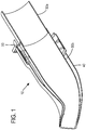
- Figures 1 and 2 illustrate an acoustic damper arrangement 20 for a combustor 10 which has an inner liner 30 configured for use at a first temperature during operation and an outer liner 40 configured for use at a second temperature lower than the first temperature during operation.
- the acoustic damper arrangement 20 includes a plurality of flexible sheets 60 and at least one hollow body 70 having an interior volume, each of the hollow bodies 70 being fixed to one of the plurality of flexible sheets 60.
- the acoustic damper arrangement 20 is configured to be fixed to both the inner liner 30 and the outer liner 40 such that the interior volume of the at least one hollow body 70 is in communication with a chamber formed by the inner liner 30, and the plurality of flexible sheets 60 accommodate expansion and contraction of the inner liner 30 relative to the outer liner 40
- the plurality of flexible sheets 60 can be fixed at one end thereof to the outer liner 40.
- At least one hollow body 70 can be fixed to one of the plurality of flexible sheets 60 at a closed end 70b of the hollow body 70.
- At least one hollow body 70 can have an open end 70a disposed radially inwardly of the closed end 70b and configured to be fixed to the inner liner 30 at at least one opening in the inner liner 30.
- At least one hollow body 70 can be fixed to the one of the plurality of flexible sheets 60 at a surface of the flexible sheet 60 facing the inner liner 30. Multiple such flexible sheets 60, spaced apart in a circumferential direction, can be included.
- the one, or more, hollow bodies 70 can possess a cross-sectional shape selected from a group consisting of: a circle, a square, a rectangle, and a teardrop. Of course other suitable shapes can be selected and will be apparent to those skilled in the art.
- the hollow bodies 70 can have a same interior volume, or can each possess different interior volumes.
- a plurality of hollow bodies 70 can be fixed to one of the plurality of flexible sheets 60 at the same or different respective axial or circumferential positions on one of the plurality of flexible sheets 60. Additionally, the number, size and shape of the air channels connecting the interior volumes of the hollow bodies 70 to the chamber defined by the inner liner 30 can be varied.
- Figure 1 illustrates an exemplary combustor 10 which can have an inner liner 30 configured for operation at a first temperature, an outer liner 40 configured for operation at a second temperature lower than the first temperature, and an acoustic damper arrangement 20 which connects the inner liner 30 with the outer liner 40.
- the combustor inner liner 30 includes a combustion piece 30a, and a transition piece 30b located downstream of the combustion piece 30a relative to a direction of gas flow during operation, with the acoustic damper arrangement 20 being disposed downstream of an overlap between the combustion piece 30a and the transition piece 30b.
- the combustor 10 can include a fuel injector for injecting fuel into a compressed air flow in the combustor to create an air-fuel mixture, and an igniter for igniting the air-fuel mixture.
- the space between the inner liner 30 and the outer liner 40 is configured to receive air compressed by a compressor part of a gas turbine. This airflow can help moderate the temperature of the inner liner 30.
- the compressed air is intermixed with fuel, and the fuel-air mixture is ignited and directed to a turbine part of the gas turbine. Accordingly, the inner liner 30 is configured for use at a higher temperature than the outer liner 40.
- the combustion piece 30a and transition piece 30b are connected at their overlap by an axial seal 50, for example, a hula seal.
- an axial seal 50 for example, a hula seal.
- Combustion can take place primarily within the combustion piece 30a, and hot combustion gas can be directed by the transition piece 30b to the turbine part of the gas turbine.
- the combustion and transition pieces 30a and 30b can thus both be directly exposed to the hot combustion gas, except for a section of one of the pieces where they overlap at the hula seal 50.
- the hollow bodies 70 can effectively provide damping volumes and can function as Helmholtz resonators when located downstream of the hula seal 50.
- the flexible sheets 60 and hollow bodies 70 With the flexible sheets 60 and hollow bodies 70 being located downstream of the axial seal 50 and thus connecting a hot part of the inner liner 30 with the relatively cool outer liner 40, the flexible sheets 60 can allow for the resulting relative movement during transient operation such as startup, shutdown or load change, during which the operating temperatures can vary.
- the flexible sheets 60 can be formed integrally with the portion of the outer liner 40 that constitutes a ring 80 which provides for fixation of the combustor 10 to the turbine casing.
- the hollow bodies 70 provide damping volumes and can function as Helmholtz resonators.
- Figs. 4 through 8 illustrate various exemplary shapes of the hollow bodies 70 and arrangements on the flexible sheets 60.
- different cross-sectional shapes for the hollow bodies such as square, rectangle, circle, droplet, can be used, as illustrated in Fig. 8 .
- These shapes and/or the arrangements can be optimized for heat transfer or for minimal flow resistance of the cooling air directed through the space between the inner liner 30 and the outer liner 40, and may be staggered, as illustrated in Figs. 5 and 6 , to minimize pressure loss in the cooling airflow, for example, to minimize the possibility of a wake generated in the cooling airflow.
- FIG. 7 illustrates that different volumes or opening sizes can be used in the hollow bodies so that, for example, hollow body 70c is optimized for different frequencies than hollow body 70d. For example, high frequency pulsations in a range of approximately 1-10 kHz, as well as low frequency pulsations in a range of approximately 50-500 Hz, can be accounted for.
- the provision of the acoustic damper arrangement 20 between the inner and outer liners can eliminate the need for other structure forming a fixed arrangement between the liners.
- the neck length is 3-15 mm and the neck diameter is 1-10 mm, although these dimensions could in principle vary.
- the acoustic damper arrangement is made from high-temperature heat-resistant (Nickel-based) alloys, such as Haynes 230, Haynes 282, Hasteloy X, or Iconel. Also, material combinations are possible, for example, St18-8 for the volume and a higher quality alloy for the neck that is in hot gas contact.
- Nickel-based alloys such as Haynes 230, Haynes 282, Hasteloy X, or Iconel.
- material combinations are possible, for example, St18-8 for the volume and a higher quality alloy for the neck that is in hot gas contact.
Landscapes
- Engineering & Computer Science (AREA)
- Chemical & Material Sciences (AREA)
- Combustion & Propulsion (AREA)
- Mechanical Engineering (AREA)
- General Engineering & Computer Science (AREA)
- Gas Burners (AREA)
- Soundproofing, Sound Blocking, And Sound Damping (AREA)
- Sealing Devices (AREA)
- Portable Nailing Machines And Staplers (AREA)
Claims (11)
- Chambre de combustion (10) comprenant :un revêtement interne (30) configuré pour le fonctionnement à une première température ;un revêtement externe (40) configuré pour le fonctionnement à une seconde température inférieure à la première température ; etun agencement d'amortisseur acoustique (20) qui raccorde le revêtement interne (30) avec le revêtement externe (40), dans laquelle :l'agencement d'amortisseur acoustique (20) comprend une pluralité de feuilles flexibles (60) et au moins un corps creux (70) ayant un volume intérieur, chacun desdits au moins un corps creux (70) étant fixé à l'une de la pluralité de feuilles flexibles (60),l'agencement d'amortisseur acoustique (20) est fixé à la fois au revêtement interne (30) et au revêtement externe (40) de sorte que le volume intérieur du au moins un corps creux (70) est en communication avec une chambre formée par le revêtement interne (30), et la pluralité de feuilles flexibles (60) acceptent la dilatation et la contraction du revêtement interne (30) par rapport au revêtement externe (40) ; etla pluralité de feuilles flexibles (60) sont fixées au niveau de leur extrémité, au revêtement externe (40) ;caractérisée en ce que le revêtement interne (30) comprend :une pièce de combustion (30a) ; etune pièce de transition (30b) positionnée en aval de la pièce de combustion (30a) par rapport à une direction d'écoulement de gaz pendant le fonctionnement,dans laquelle l'agencement d'amortisseur acoustique (20) est disposé en aval d'un chevauchement entre la pièce de combustion (30a) et la pièce de transition (30b).
- Chambre de combustion (10) selon la revendication 1, dans laquelle l'au moins un corps creux (70) est fixé à l'une de la pluralité de feuilles flexibles (60) au niveau d'une extrémité fermée (70b) du au moins un corps creux (70).
- Chambre de combustion (10) selon la revendication 1, dans laquelle l'au moins un corps creux (70) a une extrémité ouverte (70a) disposée radialement à l'intérieur de l'extrémité fermée (70b) et fixée sur le revêtement interne (30) au niveau d'au moins une ouverture dans le revêtement interne (30).
- Chambre de combustion (10) selon la revendication 1, dans laquelle l'au moins un corps creux (70) est fixé sur l'une de la pluralité de feuilles flexibles (60) au niveau d'une surface de l'une de la pluralité de feuilles flexibles (60) qui fait face au revêtement interne (30).
- Chambre de combustion (10) selon la revendication 1, dans laquelle l'au moins un corps creux (70) a une forme transversale sélectionnée dans le groupe comprenant : un cercle, un carré, un rectangle et une larme.
- Chambre de combustion (10) selon la revendication 1, dans laquelle la pluralité de corps creux (70) sont fixés sur l'une de la pluralité de feuilles flexibles (60).
- Chambre de combustion (10) selon la revendication 6, dans laquelle la pluralité de corps creux (70) ont le même volume intérieur.
- Chambre de combustion (10) selon la revendication 6, dans laquelle la pluralité de corps creux (70) ont des volumes intérieurs différents.
- Chambre de combustion (10) selon la revendication 6, dans laquelle la pluralité de corps creux (70) sont fixés à l'une de la pluralité de feuilles flexibles (60) dans des positions axiales respectives différentes sur l'une de la pluralité de feuilles flexibles (60).
- Chambre de combustion (10) selon la revendication 6, dans laquelle la pluralité de corps creux (70) sont fixés sur l'une de la pluralité de feuilles flexibles (60) à différentes positions circonférentielles respectives sur l'une de la pluralité de feuilles flexibles (60).
- Chambre de combustion (10) selon la revendication 1, dans laquelle la pluralité de corps creux (70) sont fixés sur la pluralité de feuilles flexibles (60) dans une même position circonférentielle respective et une position axiale différente respective sur la pluralité de feuilles flexibles (60).
Applications Claiming Priority (2)
| Application Number | Priority Date | Filing Date | Title |
|---|---|---|---|
| US201261698958P | 2012-09-10 | 2012-09-10 | |
| US13/689,926 US8684130B1 (en) | 2012-09-10 | 2012-11-30 | Damping system for combustor |
Publications (2)
| Publication Number | Publication Date |
|---|---|
| EP2716972A1 EP2716972A1 (fr) | 2014-04-09 |
| EP2716972B1 true EP2716972B1 (fr) | 2019-04-17 |
Family
ID=49033934
Family Applications (1)
| Application Number | Title | Priority Date | Filing Date |
|---|---|---|---|
| EP13181701.7A Active EP2716972B1 (fr) | 2012-09-10 | 2013-08-26 | Système d'amortisseur acoustique destiné à une chambre de combustion |
Country Status (8)
| Country | Link |
|---|---|
| US (1) | US8684130B1 (fr) |
| EP (1) | EP2716972B1 (fr) |
| JP (1) | JP5734375B2 (fr) |
| KR (1) | KR101551673B1 (fr) |
| CN (1) | CN103672971B (fr) |
| CA (1) | CA2826099C (fr) |
| RU (1) | RU2551707C2 (fr) |
| SA (1) | SA113340835B1 (fr) |
Families Citing this family (11)
| Publication number | Priority date | Publication date | Assignee | Title |
|---|---|---|---|---|
| GB2516286B (en) * | 2013-07-18 | 2016-08-17 | Rolls Royce Plc | A duct and method for damping pressure waves caused by thermoacoustic instability |
| US10267523B2 (en) * | 2014-09-15 | 2019-04-23 | Ansaldo Energia Ip Uk Limited | Combustor dome damper system |
| EP3227611A1 (fr) * | 2014-12-01 | 2017-10-11 | Siemens Aktiengesellschaft | Résonateurs comprenant des tubes de mesure interchangeables pour des turbines à gaz |
| EP3048370A1 (fr) | 2015-01-23 | 2016-07-27 | Siemens Aktiengesellschaft | Chambre de combustion pour un moteur de turbine à gaz |
| RU2643927C1 (ru) * | 2016-06-06 | 2018-02-06 | Акционерное общество Центральный научно-исследовательский институт специального машиностроения | Камера сгорания прямоточного воздушно-реактивного двигателя из композиционных материалов |
| US10228138B2 (en) | 2016-12-02 | 2019-03-12 | General Electric Company | System and apparatus for gas turbine combustor inner cap and resonating tubes |
| US10220474B2 (en) | 2016-12-02 | 2019-03-05 | General Electricd Company | Method and apparatus for gas turbine combustor inner cap and high frequency acoustic dampers |
| US10221769B2 (en) | 2016-12-02 | 2019-03-05 | General Electric Company | System and apparatus for gas turbine combustor inner cap and extended resonating tubes |
| US11506382B2 (en) | 2019-09-12 | 2022-11-22 | General Electric Company | System and method for acoustic dampers with multiple volumes in a combustion chamber front panel |
| CN115682033A (zh) * | 2021-07-28 | 2023-02-03 | 北京航空航天大学 | 防振燃烧室以及燃烧室防振方法 |
| CN113719861B (zh) * | 2021-09-10 | 2022-12-06 | 中国联合重型燃气轮机技术有限公司 | 燃烧室和具有该燃烧室的燃气轮机 |
Family Cites Families (18)
| Publication number | Priority date | Publication date | Assignee | Title |
|---|---|---|---|---|
| DE2135824C3 (de) * | 1971-07-17 | 1981-10-29 | Robert Bosch Gmbh, 7000 Stuttgart | Luftmengenmesser mit einer im Ansaugkanal einer Brennkraftmaschine im wesentlichen quer zur Ansaugluftströmung angeordnete Stauscheibe |
| DE19506511C2 (de) * | 1995-02-24 | 1998-08-27 | Fraunhofer Ges Forschung | Plattenresonator |
| US5685157A (en) * | 1995-05-26 | 1997-11-11 | General Electric Company | Acoustic damper for a gas turbine engine combustor |
| US6334310B1 (en) | 2000-06-02 | 2002-01-01 | General Electric Company | Fracture resistant support structure for a hula seal in a turbine combustor and related method |
| US6530221B1 (en) * | 2000-09-21 | 2003-03-11 | Siemens Westinghouse Power Corporation | Modular resonators for suppressing combustion instabilities in gas turbine power plants |
| WO2003023281A1 (fr) * | 2001-09-07 | 2003-03-20 | Alstom Technology Ltd | Ensemble amortisseur concu pour reduire les pulsations d'une chambre de combustion dans une installation de turbine a gaz |
| US7010921B2 (en) * | 2004-06-01 | 2006-03-14 | General Electric Company | Method and apparatus for cooling combustor liner and transition piece of a gas turbine |
| US7334408B2 (en) * | 2004-09-21 | 2008-02-26 | Siemens Aktiengesellschaft | Combustion chamber for a gas turbine with at least two resonator devices |
| US7552796B2 (en) * | 2006-04-27 | 2009-06-30 | United Technologies Corporation | Turbine engine tailcone resonator |
| US8079219B2 (en) | 2008-09-30 | 2011-12-20 | General Electric Company | Impingement cooled combustor seal |
| US8025122B2 (en) * | 2008-11-06 | 2011-09-27 | The Boeing Company | Acoustically treated exhaust centerbody for jet engines and associated methods |
| CN104033926B (zh) * | 2009-02-27 | 2019-04-16 | 三菱日立电力系统株式会社 | 燃烧器及具备该燃烧器的燃气轮机 |
| US8429919B2 (en) | 2009-05-28 | 2013-04-30 | General Electric Company | Expansion hula seals |
| EP2362147B1 (fr) * | 2010-02-22 | 2012-12-26 | Alstom Technology Ltd | Dispositif de combustion pour turbine à gaz |
| EP2383515B1 (fr) * | 2010-04-28 | 2013-06-19 | Siemens Aktiengesellschaft | Système de brûleur pour l'amortissement d'un tel système de brûleur |
| US8621842B2 (en) * | 2010-05-05 | 2014-01-07 | Hamilton Sundstrand Corporation | Exhaust silencer convection cooling |
| US8973365B2 (en) | 2010-10-29 | 2015-03-10 | Solar Turbines Incorporated | Gas turbine combustor with mounting for Helmholtz resonators |
| US20120180500A1 (en) | 2011-01-13 | 2012-07-19 | General Electric Company | System for damping vibration in a gas turbine engine |
-
2012
- 2012-11-30 US US13/689,926 patent/US8684130B1/en active Active
-
2013
- 2013-08-26 EP EP13181701.7A patent/EP2716972B1/fr active Active
- 2013-09-04 CA CA2826099A patent/CA2826099C/fr not_active Expired - Fee Related
- 2013-09-09 RU RU2013141399/06A patent/RU2551707C2/ru active
- 2013-09-09 SA SA113340835A patent/SA113340835B1/ar unknown
- 2013-09-09 KR KR1020130107807A patent/KR101551673B1/ko not_active IP Right Cessation
- 2013-09-10 CN CN201310408451.4A patent/CN103672971B/zh active Active
- 2013-09-10 JP JP2013187373A patent/JP5734375B2/ja not_active Expired - Fee Related
Non-Patent Citations (1)
| Title |
|---|
| None * |
Also Published As
| Publication number | Publication date |
|---|---|
| KR20140034079A (ko) | 2014-03-19 |
| JP2014051983A (ja) | 2014-03-20 |
| US20140069738A1 (en) | 2014-03-13 |
| CA2826099C (fr) | 2016-02-23 |
| RU2551707C2 (ru) | 2015-05-27 |
| SA113340835B1 (ar) | 2015-09-01 |
| JP5734375B2 (ja) | 2015-06-17 |
| EP2716972A1 (fr) | 2014-04-09 |
| RU2013141399A (ru) | 2015-03-20 |
| CN103672971B (zh) | 2015-10-07 |
| CN103672971A (zh) | 2014-03-26 |
| US8684130B1 (en) | 2014-04-01 |
| CA2826099A1 (fr) | 2014-03-10 |
| KR101551673B1 (ko) | 2015-09-09 |
Similar Documents
| Publication | Publication Date | Title |
|---|---|---|
| EP2716972B1 (fr) | Système d'amortisseur acoustique destiné à une chambre de combustion | |
| US8973365B2 (en) | Gas turbine combustor with mounting for Helmholtz resonators | |
| EP1666795B1 (fr) | Atténuateur acoustique | |
| US8544277B2 (en) | Turbulated aft-end liner assembly and cooling method | |
| JP5627926B2 (ja) | 拡大フラ・シール | |
| EP2280225A3 (fr) | Chambres de combustion de turbine à gaz à double paroi à refroidissement par effusion | |
| EP3315866B1 (fr) | Ensemble de chambre de combustion comportant un composant auxiliaire monté | |
| NO344325B1 (en) | Gas turbine combustion acoustic damping system | |
| US11041625B2 (en) | Fuel nozzle with narrow-band acoustic damper | |
| US9394830B2 (en) | Inverted cap igniter tube | |
| KR20050016140A (ko) | 재연소기 장치 | |
| EP1952061B1 (fr) | Ensemble brûleur annulaire | |
| EP2573465A2 (fr) | Chambre de combustion et procédé de conditionnement de l'écoulement à travers une chambre de combustion | |
| EP3604926B1 (fr) | Panneau de bouclier thermique pour utilisation dans une chambre de combustion d'une turbine à gaz | |
| US20230064335A1 (en) | Cooling for continuous ignition devices | |
| JP2017166483A (ja) | 燃焼ライナ冷却 |
Legal Events
| Date | Code | Title | Description |
|---|---|---|---|
| PUAI | Public reference made under article 153(3) epc to a published international application that has entered the european phase |
Free format text: ORIGINAL CODE: 0009012 |
|
| AK | Designated contracting states |
Kind code of ref document: A1 Designated state(s): AL AT BE BG CH CY CZ DE DK EE ES FI FR GB GR HR HU IE IS IT LI LT LU LV MC MK MT NL NO PL PT RO RS SE SI SK SM TR |
|
| AX | Request for extension of the european patent |
Extension state: BA ME |
|
| 17P | Request for examination filed |
Effective date: 20130829 |
|
| RAP1 | Party data changed (applicant data changed or rights of an application transferred) |
Owner name: GENERAL ELECTRIC TECHNOLOGY GMBH |
|
| RAP1 | Party data changed (applicant data changed or rights of an application transferred) |
Owner name: ANSALDO ENERGIA SWITZERLAND AG |
|
| STAA | Information on the status of an ep patent application or granted ep patent |
Free format text: STATUS: EXAMINATION IS IN PROGRESS |
|
| 17Q | First examination report despatched |
Effective date: 20180208 |
|
| GRAP | Despatch of communication of intention to grant a patent |
Free format text: ORIGINAL CODE: EPIDOSNIGR1 |
|
| STAA | Information on the status of an ep patent application or granted ep patent |
Free format text: STATUS: GRANT OF PATENT IS INTENDED |
|
| INTG | Intention to grant announced |
Effective date: 20181122 |
|
| RIN1 | Information on inventor provided before grant (corrected) |
Inventor name: JORGENSEN, STEVEN W Inventor name: PENNELL, DOUGLAS ANTHONY Inventor name: BOTHIEN, MIRKO RUBEN |
|
| GRAS | Grant fee paid |
Free format text: ORIGINAL CODE: EPIDOSNIGR3 |
|
| GRAA | (expected) grant |
Free format text: ORIGINAL CODE: 0009210 |
|
| STAA | Information on the status of an ep patent application or granted ep patent |
Free format text: STATUS: THE PATENT HAS BEEN GRANTED |
|
| AK | Designated contracting states |
Kind code of ref document: B1 Designated state(s): AL AT BE BG CH CY CZ DE DK EE ES FI FR GB GR HR HU IE IS IT LI LT LU LV MC MK MT NL NO PL PT RO RS SE SI SK SM TR |
|
| REG | Reference to a national code |
Ref country code: GB Ref legal event code: FG4D |
|
| REG | Reference to a national code |
Ref country code: CH Ref legal event code: EP |
|
| REG | Reference to a national code |
Ref country code: DE Ref legal event code: R096 Ref document number: 602013053949 Country of ref document: DE |
|
| REG | Reference to a national code |
Ref country code: AT Ref legal event code: REF Ref document number: 1121944 Country of ref document: AT Kind code of ref document: T Effective date: 20190515 Ref country code: IE Ref legal event code: FG4D |
|
| REG | Reference to a national code |
Ref country code: NL Ref legal event code: MP Effective date: 20190417 |
|
| REG | Reference to a national code |
Ref country code: LT Ref legal event code: MG4D |
|
| PG25 | Lapsed in a contracting state [announced via postgrant information from national office to epo] |
Ref country code: NL Free format text: LAPSE BECAUSE OF FAILURE TO SUBMIT A TRANSLATION OF THE DESCRIPTION OR TO PAY THE FEE WITHIN THE PRESCRIBED TIME-LIMIT Effective date: 20190417 |
|
| PG25 | Lapsed in a contracting state [announced via postgrant information from national office to epo] |
Ref country code: PT Free format text: LAPSE BECAUSE OF FAILURE TO SUBMIT A TRANSLATION OF THE DESCRIPTION OR TO PAY THE FEE WITHIN THE PRESCRIBED TIME-LIMIT Effective date: 20190817 Ref country code: ES Free format text: LAPSE BECAUSE OF FAILURE TO SUBMIT A TRANSLATION OF THE DESCRIPTION OR TO PAY THE FEE WITHIN THE PRESCRIBED TIME-LIMIT Effective date: 20190417 Ref country code: LT Free format text: LAPSE BECAUSE OF FAILURE TO SUBMIT A TRANSLATION OF THE DESCRIPTION OR TO PAY THE FEE WITHIN THE PRESCRIBED TIME-LIMIT Effective date: 20190417 Ref country code: NO Free format text: LAPSE BECAUSE OF FAILURE TO SUBMIT A TRANSLATION OF THE DESCRIPTION OR TO PAY THE FEE WITHIN THE PRESCRIBED TIME-LIMIT Effective date: 20190717 Ref country code: FI Free format text: LAPSE BECAUSE OF FAILURE TO SUBMIT A TRANSLATION OF THE DESCRIPTION OR TO PAY THE FEE WITHIN THE PRESCRIBED TIME-LIMIT Effective date: 20190417 Ref country code: HR Free format text: LAPSE BECAUSE OF FAILURE TO SUBMIT A TRANSLATION OF THE DESCRIPTION OR TO PAY THE FEE WITHIN THE PRESCRIBED TIME-LIMIT Effective date: 20190417 Ref country code: SE Free format text: LAPSE BECAUSE OF FAILURE TO SUBMIT A TRANSLATION OF THE DESCRIPTION OR TO PAY THE FEE WITHIN THE PRESCRIBED TIME-LIMIT Effective date: 20190417 Ref country code: AL Free format text: LAPSE BECAUSE OF FAILURE TO SUBMIT A TRANSLATION OF THE DESCRIPTION OR TO PAY THE FEE WITHIN THE PRESCRIBED TIME-LIMIT Effective date: 20190417 |
|
| PG25 | Lapsed in a contracting state [announced via postgrant information from national office to epo] |
Ref country code: RS Free format text: LAPSE BECAUSE OF FAILURE TO SUBMIT A TRANSLATION OF THE DESCRIPTION OR TO PAY THE FEE WITHIN THE PRESCRIBED TIME-LIMIT Effective date: 20190417 Ref country code: PL Free format text: LAPSE BECAUSE OF FAILURE TO SUBMIT A TRANSLATION OF THE DESCRIPTION OR TO PAY THE FEE WITHIN THE PRESCRIBED TIME-LIMIT Effective date: 20190417 Ref country code: GR Free format text: LAPSE BECAUSE OF FAILURE TO SUBMIT A TRANSLATION OF THE DESCRIPTION OR TO PAY THE FEE WITHIN THE PRESCRIBED TIME-LIMIT Effective date: 20190718 Ref country code: LV Free format text: LAPSE BECAUSE OF FAILURE TO SUBMIT A TRANSLATION OF THE DESCRIPTION OR TO PAY THE FEE WITHIN THE PRESCRIBED TIME-LIMIT Effective date: 20190417 Ref country code: BG Free format text: LAPSE BECAUSE OF FAILURE TO SUBMIT A TRANSLATION OF THE DESCRIPTION OR TO PAY THE FEE WITHIN THE PRESCRIBED TIME-LIMIT Effective date: 20190717 |
|
| REG | Reference to a national code |
Ref country code: AT Ref legal event code: MK05 Ref document number: 1121944 Country of ref document: AT Kind code of ref document: T Effective date: 20190417 |
|
| PG25 | Lapsed in a contracting state [announced via postgrant information from national office to epo] |
Ref country code: IS Free format text: LAPSE BECAUSE OF FAILURE TO SUBMIT A TRANSLATION OF THE DESCRIPTION OR TO PAY THE FEE WITHIN THE PRESCRIBED TIME-LIMIT Effective date: 20190817 |
|
| REG | Reference to a national code |
Ref country code: DE Ref legal event code: R097 Ref document number: 602013053949 Country of ref document: DE |
|
| PG25 | Lapsed in a contracting state [announced via postgrant information from national office to epo] |
Ref country code: CZ Free format text: LAPSE BECAUSE OF FAILURE TO SUBMIT A TRANSLATION OF THE DESCRIPTION OR TO PAY THE FEE WITHIN THE PRESCRIBED TIME-LIMIT Effective date: 20190417 Ref country code: RO Free format text: LAPSE BECAUSE OF FAILURE TO SUBMIT A TRANSLATION OF THE DESCRIPTION OR TO PAY THE FEE WITHIN THE PRESCRIBED TIME-LIMIT Effective date: 20190417 Ref country code: SK Free format text: LAPSE BECAUSE OF FAILURE TO SUBMIT A TRANSLATION OF THE DESCRIPTION OR TO PAY THE FEE WITHIN THE PRESCRIBED TIME-LIMIT Effective date: 20190417 Ref country code: EE Free format text: LAPSE BECAUSE OF FAILURE TO SUBMIT A TRANSLATION OF THE DESCRIPTION OR TO PAY THE FEE WITHIN THE PRESCRIBED TIME-LIMIT Effective date: 20190417 Ref country code: AT Free format text: LAPSE BECAUSE OF FAILURE TO SUBMIT A TRANSLATION OF THE DESCRIPTION OR TO PAY THE FEE WITHIN THE PRESCRIBED TIME-LIMIT Effective date: 20190417 Ref country code: DK Free format text: LAPSE BECAUSE OF FAILURE TO SUBMIT A TRANSLATION OF THE DESCRIPTION OR TO PAY THE FEE WITHIN THE PRESCRIBED TIME-LIMIT Effective date: 20190417 |
|
| PLBE | No opposition filed within time limit |
Free format text: ORIGINAL CODE: 0009261 |
|
| STAA | Information on the status of an ep patent application or granted ep patent |
Free format text: STATUS: NO OPPOSITION FILED WITHIN TIME LIMIT |
|
| PG25 | Lapsed in a contracting state [announced via postgrant information from national office to epo] |
Ref country code: IT Free format text: LAPSE BECAUSE OF FAILURE TO SUBMIT A TRANSLATION OF THE DESCRIPTION OR TO PAY THE FEE WITHIN THE PRESCRIBED TIME-LIMIT Effective date: 20190417 Ref country code: SM Free format text: LAPSE BECAUSE OF FAILURE TO SUBMIT A TRANSLATION OF THE DESCRIPTION OR TO PAY THE FEE WITHIN THE PRESCRIBED TIME-LIMIT Effective date: 20190417 |
|
| 26N | No opposition filed |
Effective date: 20200120 |
|
| PG25 | Lapsed in a contracting state [announced via postgrant information from national office to epo] |
Ref country code: TR Free format text: LAPSE BECAUSE OF FAILURE TO SUBMIT A TRANSLATION OF THE DESCRIPTION OR TO PAY THE FEE WITHIN THE PRESCRIBED TIME-LIMIT Effective date: 20190417 |
|
| GBPC | Gb: european patent ceased through non-payment of renewal fee |
Effective date: 20190826 |
|
| PG25 | Lapsed in a contracting state [announced via postgrant information from national office to epo] |
Ref country code: MC Free format text: LAPSE BECAUSE OF FAILURE TO SUBMIT A TRANSLATION OF THE DESCRIPTION OR TO PAY THE FEE WITHIN THE PRESCRIBED TIME-LIMIT Effective date: 20190417 Ref country code: LI Free format text: LAPSE BECAUSE OF NON-PAYMENT OF DUE FEES Effective date: 20190831 Ref country code: CH Free format text: LAPSE BECAUSE OF NON-PAYMENT OF DUE FEES Effective date: 20190831 Ref country code: LU Free format text: LAPSE BECAUSE OF NON-PAYMENT OF DUE FEES Effective date: 20190826 Ref country code: SI Free format text: LAPSE BECAUSE OF FAILURE TO SUBMIT A TRANSLATION OF THE DESCRIPTION OR TO PAY THE FEE WITHIN THE PRESCRIBED TIME-LIMIT Effective date: 20190417 |
|
| REG | Reference to a national code |
Ref country code: BE Ref legal event code: MM Effective date: 20190831 |
|
| PG25 | Lapsed in a contracting state [announced via postgrant information from national office to epo] |
Ref country code: IE Free format text: LAPSE BECAUSE OF NON-PAYMENT OF DUE FEES Effective date: 20190826 Ref country code: FR Free format text: LAPSE BECAUSE OF NON-PAYMENT OF DUE FEES Effective date: 20190831 |
|
| PG25 | Lapsed in a contracting state [announced via postgrant information from national office to epo] |
Ref country code: BE Free format text: LAPSE BECAUSE OF NON-PAYMENT OF DUE FEES Effective date: 20190831 Ref country code: GB Free format text: LAPSE BECAUSE OF NON-PAYMENT OF DUE FEES Effective date: 20190826 |
|
| PG25 | Lapsed in a contracting state [announced via postgrant information from national office to epo] |
Ref country code: CY Free format text: LAPSE BECAUSE OF FAILURE TO SUBMIT A TRANSLATION OF THE DESCRIPTION OR TO PAY THE FEE WITHIN THE PRESCRIBED TIME-LIMIT Effective date: 20190417 |
|
| PG25 | Lapsed in a contracting state [announced via postgrant information from national office to epo] |
Ref country code: MT Free format text: LAPSE BECAUSE OF FAILURE TO SUBMIT A TRANSLATION OF THE DESCRIPTION OR TO PAY THE FEE WITHIN THE PRESCRIBED TIME-LIMIT Effective date: 20190417 Ref country code: HU Free format text: LAPSE BECAUSE OF FAILURE TO SUBMIT A TRANSLATION OF THE DESCRIPTION OR TO PAY THE FEE WITHIN THE PRESCRIBED TIME-LIMIT; INVALID AB INITIO Effective date: 20130826 |
|
| PG25 | Lapsed in a contracting state [announced via postgrant information from national office to epo] |
Ref country code: MK Free format text: LAPSE BECAUSE OF FAILURE TO SUBMIT A TRANSLATION OF THE DESCRIPTION OR TO PAY THE FEE WITHIN THE PRESCRIBED TIME-LIMIT Effective date: 20190417 |
|
| PGFP | Annual fee paid to national office [announced via postgrant information from national office to epo] |
Ref country code: DE Payment date: 20230703 Year of fee payment: 11 |