EP2716484A1 - Fuel tank for heavy construction equipment - Google Patents
Fuel tank for heavy construction equipment Download PDFInfo
- Publication number
- EP2716484A1 EP2716484A1 EP20110866492 EP11866492A EP2716484A1 EP 2716484 A1 EP2716484 A1 EP 2716484A1 EP 20110866492 EP20110866492 EP 20110866492 EP 11866492 A EP11866492 A EP 11866492A EP 2716484 A1 EP2716484 A1 EP 2716484A1
- Authority
- EP
- European Patent Office
- Prior art keywords
- fuel
- fuel tank
- moisture
- lower cover
- tank
- Prior art date
- Legal status (The legal status is an assumption and is not a legal conclusion. Google has not performed a legal analysis and makes no representation as to the accuracy of the status listed.)
- Granted
Links
Images

Classifications
-
- B—PERFORMING OPERATIONS; TRANSPORTING
- B60—VEHICLES IN GENERAL
- B60K—ARRANGEMENT OR MOUNTING OF PROPULSION UNITS OR OF TRANSMISSIONS IN VEHICLES; ARRANGEMENT OR MOUNTING OF PLURAL DIVERSE PRIME-MOVERS IN VEHICLES; AUXILIARY DRIVES FOR VEHICLES; INSTRUMENTATION OR DASHBOARDS FOR VEHICLES; ARRANGEMENTS IN CONNECTION WITH COOLING, AIR INTAKE, GAS EXHAUST OR FUEL SUPPLY OF PROPULSION UNITS IN VEHICLES
- B60K15/00—Arrangement in connection with fuel supply of combustion engines or other fuel consuming energy converters, e.g. fuel cells; Mounting or construction of fuel tanks
- B60K15/03—Fuel tanks
- B60K15/073—Tank construction specially adapted to the vehicle
-
- B—PERFORMING OPERATIONS; TRANSPORTING
- B60—VEHICLES IN GENERAL
- B60K—ARRANGEMENT OR MOUNTING OF PROPULSION UNITS OR OF TRANSMISSIONS IN VEHICLES; ARRANGEMENT OR MOUNTING OF PLURAL DIVERSE PRIME-MOVERS IN VEHICLES; AUXILIARY DRIVES FOR VEHICLES; INSTRUMENTATION OR DASHBOARDS FOR VEHICLES; ARRANGEMENTS IN CONNECTION WITH COOLING, AIR INTAKE, GAS EXHAUST OR FUEL SUPPLY OF PROPULSION UNITS IN VEHICLES
- B60K15/00—Arrangement in connection with fuel supply of combustion engines or other fuel consuming energy converters, e.g. fuel cells; Mounting or construction of fuel tanks
- B60K15/03—Fuel tanks
- B60K15/077—Fuel tanks with means modifying or controlling distribution or motion of fuel, e.g. to prevent noise, surge, splash or fuel starvation
-
- E—FIXED CONSTRUCTIONS
- E02—HYDRAULIC ENGINEERING; FOUNDATIONS; SOIL SHIFTING
- E02F—DREDGING; SOIL-SHIFTING
- E02F9/00—Component parts of dredgers or soil-shifting machines, not restricted to one of the kinds covered by groups E02F3/00 - E02F7/00
-
- F—MECHANICAL ENGINEERING; LIGHTING; HEATING; WEAPONS; BLASTING
- F02—COMBUSTION ENGINES; HOT-GAS OR COMBUSTION-PRODUCT ENGINE PLANTS
- F02M—SUPPLYING COMBUSTION ENGINES IN GENERAL WITH COMBUSTIBLE MIXTURES OR CONSTITUENTS THEREOF
- F02M31/00—Apparatus for thermally treating combustion-air, fuel, or fuel-air mixture
- F02M31/02—Apparatus for thermally treating combustion-air, fuel, or fuel-air mixture for heating
- F02M31/12—Apparatus for thermally treating combustion-air, fuel, or fuel-air mixture for heating electrically
- F02M31/125—Fuel
-
- F—MECHANICAL ENGINEERING; LIGHTING; HEATING; WEAPONS; BLASTING
- F02—COMBUSTION ENGINES; HOT-GAS OR COMBUSTION-PRODUCT ENGINE PLANTS
- F02M—SUPPLYING COMBUSTION ENGINES IN GENERAL WITH COMBUSTIBLE MIXTURES OR CONSTITUENTS THEREOF
- F02M37/00—Apparatus or systems for feeding liquid fuel from storage containers to carburettors or fuel-injection apparatus; Arrangements for purifying liquid fuel specially adapted for, or arranged on, internal-combustion engines
- F02M37/0076—Details of the fuel feeding system related to the fuel tank
-
- F—MECHANICAL ENGINEERING; LIGHTING; HEATING; WEAPONS; BLASTING
- F02—COMBUSTION ENGINES; HOT-GAS OR COMBUSTION-PRODUCT ENGINE PLANTS
- F02M—SUPPLYING COMBUSTION ENGINES IN GENERAL WITH COMBUSTIBLE MIXTURES OR CONSTITUENTS THEREOF
- F02M37/00—Apparatus or systems for feeding liquid fuel from storage containers to carburettors or fuel-injection apparatus; Arrangements for purifying liquid fuel specially adapted for, or arranged on, internal-combustion engines
- F02M37/22—Arrangements for purifying liquid fuel specially adapted for, or arranged on, internal-combustion engines, e.g. arrangements in the feeding system
- F02M37/30—Arrangements for purifying liquid fuel specially adapted for, or arranged on, internal-combustion engines, e.g. arrangements in the feeding system characterised by heating means
-
- B—PERFORMING OPERATIONS; TRANSPORTING
- B60—VEHICLES IN GENERAL
- B60K—ARRANGEMENT OR MOUNTING OF PROPULSION UNITS OR OF TRANSMISSIONS IN VEHICLES; ARRANGEMENT OR MOUNTING OF PLURAL DIVERSE PRIME-MOVERS IN VEHICLES; AUXILIARY DRIVES FOR VEHICLES; INSTRUMENTATION OR DASHBOARDS FOR VEHICLES; ARRANGEMENTS IN CONNECTION WITH COOLING, AIR INTAKE, GAS EXHAUST OR FUEL SUPPLY OF PROPULSION UNITS IN VEHICLES
- B60K15/00—Arrangement in connection with fuel supply of combustion engines or other fuel consuming energy converters, e.g. fuel cells; Mounting or construction of fuel tanks
- B60K15/03—Fuel tanks
- B60K2015/03328—Arrangements or special measures related to fuel tanks or fuel handling
- B60K2015/03427—Arrangements or special measures related to fuel tanks or fuel handling for heating fuel, e.g. to avoiding freezing
-
- B—PERFORMING OPERATIONS; TRANSPORTING
- B60—VEHICLES IN GENERAL
- B60K—ARRANGEMENT OR MOUNTING OF PROPULSION UNITS OR OF TRANSMISSIONS IN VEHICLES; ARRANGEMENT OR MOUNTING OF PLURAL DIVERSE PRIME-MOVERS IN VEHICLES; AUXILIARY DRIVES FOR VEHICLES; INSTRUMENTATION OR DASHBOARDS FOR VEHICLES; ARRANGEMENTS IN CONNECTION WITH COOLING, AIR INTAKE, GAS EXHAUST OR FUEL SUPPLY OF PROPULSION UNITS IN VEHICLES
- B60K15/00—Arrangement in connection with fuel supply of combustion engines or other fuel consuming energy converters, e.g. fuel cells; Mounting or construction of fuel tanks
- B60K15/03—Fuel tanks
- B60K2015/03328—Arrangements or special measures related to fuel tanks or fuel handling
- B60K2015/0344—Arrangements or special measures related to fuel tanks or fuel handling comprising baffles
-
- E—FIXED CONSTRUCTIONS
- E02—HYDRAULIC ENGINEERING; FOUNDATIONS; SOIL SHIFTING
- E02F—DREDGING; SOIL-SHIFTING
- E02F9/00—Component parts of dredgers or soil-shifting machines, not restricted to one of the kinds covered by groups E02F3/00 - E02F7/00
- E02F9/08—Superstructures; Supports for superstructures
- E02F9/0858—Arrangement of component parts installed on superstructures not otherwise provided for, e.g. electric components, fenders, air-conditioning units
- E02F9/0883—Tanks, e.g. oil tank, urea tank, fuel tank
-
- Y—GENERAL TAGGING OF NEW TECHNOLOGICAL DEVELOPMENTS; GENERAL TAGGING OF CROSS-SECTIONAL TECHNOLOGIES SPANNING OVER SEVERAL SECTIONS OF THE IPC; TECHNICAL SUBJECTS COVERED BY FORMER USPC CROSS-REFERENCE ART COLLECTIONS [XRACs] AND DIGESTS
- Y02—TECHNOLOGIES OR APPLICATIONS FOR MITIGATION OR ADAPTATION AGAINST CLIMATE CHANGE
- Y02T—CLIMATE CHANGE MITIGATION TECHNOLOGIES RELATED TO TRANSPORTATION
- Y02T10/00—Road transport of goods or passengers
- Y02T10/10—Internal combustion engine [ICE] based vehicles
- Y02T10/12—Improving ICE efficiencies
-
- Y—GENERAL TAGGING OF NEW TECHNOLOGICAL DEVELOPMENTS; GENERAL TAGGING OF CROSS-SECTIONAL TECHNOLOGIES SPANNING OVER SEVERAL SECTIONS OF THE IPC; TECHNICAL SUBJECTS COVERED BY FORMER USPC CROSS-REFERENCE ART COLLECTIONS [XRACs] AND DIGESTS
- Y10—TECHNICAL SUBJECTS COVERED BY FORMER USPC
- Y10T—TECHNICAL SUBJECTS COVERED BY FORMER US CLASSIFICATION
- Y10T137/00—Fluid handling
- Y10T137/794—With means for separating solid material from the fluid
Definitions
- the present invention relates to a fuel tank for a construction machine. More particularly, the present invention relates to a fuel tank for a construction machine, which can prevent a diesel heater from being inoperable due to an inflow of moisture that is generated within a fuel tank of the construction machine, such as an excavator, in an extremely cold area (e.g., work environment in temperatures below -15°C) and make the moisture within the fuel tank be filtered through a water separator and be supplied to an engine side.
- a fuel tank for a construction machine which can prevent a diesel heater from being inoperable due to an inflow of moisture that is generated within a fuel tank of the construction machine, such as an excavator, in an extremely cold area (e.g., work environment in temperatures below -15°C) and make the moisture within the fuel tank be filtered through a water separator and be supplied to an engine side.
- an extremely cold area e.g., work environment in temperatures below -15°C
- diesel fuel that is used in a diesel engine has the characteristics that if an outdoor temperature is lowered below -15°C in winter seasons, paraffinic wax components are extracted from the fuel due to freezing phenomena in the fuel, and fuel flexibility is greatly deteriorated in comparison to that at room temperature. Further, if the diesel engine starts to be driven in a state where the paraffinic wax components are extracted from the diesel fuel, the extracted wax components, which are sucked into the engine, may clog filter paper in a fuel filter as the wax components pass through the fuel filter, and this may cause engine start inferiority of the machine, engine stalling, white smoke generation, and the like. On the other hand, about 20% of the fuel that is supplied from the fuel tank to the engine side is injected and combusted, and the remaining 80% of the fuel returns to the fuel tank.
- a fuel tank for a construction machine in the related art includes a baffle plate 2 formed inside the fuel tank 1 to prevent fuel flow during movement of the machine; a lower cover 3 mounted on a through hole formed on a bottom surface of the fuel tank to keep sealing without leaking fuel; a fuel suction port 4 mounted on the lower cover 3 to communicate with a fuel suction pipe so as to supply the fuel from the fuel tank 1 to an engine side; a suction filter 5 mounted on the fuel suction port 4 to filter contaminants included in the fuel; a diesel heater fuel suction port 6 mounted on the lower cover 3 to communicate with a diesel heater suction pipe of a line of the fuel that is supplied to a diesel heater which generates heat using a cooling water in the engine and enables a fan in a cab to operate before a work starts in order to improve the work condition in the cab in an extremely cold area; a drain port 7 mounted on the lower cover 3 to discharge the moisture included in the fuel; and a fuel return port 8 mounted on the bottom surface
- moisture (which may be water drops) may be formed on an inner surface of the fuel tank 1 that is made of a metal plate due to an external temperature change and may be mixed with the fuel in the fuel tank for a construction machine in the related art. Further, due to the exhaust gas emission regulations of the machine, the temperature of the fuel that returns from the engine side to the fuel tank 1 is further increased, and thus the moisture condensation rate is relatively heightened. Due to this, the high-temperature fuel that returns to the fuel tank 1 through the fuel return port 8 is mixed with the fuel in the fuel tank 1, and in this process, the high-temperature fuel is cooled to cause the moisture to be generated.
- the fuel return port 8 is positioned adjacent to the fuel suction ports 4 and 6, the fuel that returns to the fuel tank 1 through the fuel return port 8 stirs moisture grains that are precipitated on the bottom surface of the fuel tank 1, and thus the moisture that flows in the fuel tank 1 is mixed with the fuel.
- the present invention has been made to solve the above-mentioned problems occurring in the related art, and one subject to be achieved by the present invention is to provide a fuel tank for a construction machine, which can prevent a diesel heater from being inoperable due to an inflow of moisture that is generated due to moisture condensation in the fuel tank into a diesel heater fuel line in the case where the machine is in an engine-off state for a long time in an extremely cold area, and make the moisture within the fuel tank be filtered through a water separator, so that a reserved operation of a diesel heater can be performed smoothly.
- a fuel tank for a construction machine which includes a baffle plate formed inside the fuel tank to prevent fuel flow during movement of the machine; a lower cover mounted on a through hole formed on a bottom surface of the fuel tank to keep sealing without leaking fuel; a fuel suction port mounted on the lower cover to communicate with a fuel suction pipe so as to supply the fuel from the fuel tank to an engine side; a suction filter mounted on the fuel suction port to filter contaminants included in the fuel; a diesel heater fuel suction port mounted on the lower cover and having an inlet that is formed to be bent toward the bottom surface of the fuel tank so that moisture, which is generated and dropped within the fuel tank in the case where the machine in an engine-off state is put in an extremely cold area, is prevented from flowing into the inlet and being supplied to a diesel heater suction pipe; a drain port mounted on the lower cover to discharge the moisture included in the fuel; and a fuel return port mounted on the bottom surface in the fuel tank to communicate with a fuel return pipe
- the fuel tank for a construction machine as described above has the following advantages.
- the moisture generated within the fuel tank is prevented from flowing into the diesel heater fuel line due to the shape change of the diesel heater fuel suction port in the fuel tank that communicates with the diesel heater suction pipe, and thus smooth operation of the diesel heater can be secured. Further, the moisture that is mixed with the fuel in the fuel tank is filtered through the water separator, and thus the engine can start smoothly.
- a fuel tank for a construction machine includes a baffle plate 2 formed inside the fuel tank 1 to prevent fuel flow during movement of the machine; a lower cover 3 mounted on a through hole formed on a bottom surface of the fuel tank to keep sealing without leaking fuel; a fuel suction port 4 mounted on the lower cover 3 to communicate with a fuel suction pipe (not illustrated) so as to supply the fuel from the fuel tank 1 to an engine side; a suction filter 5 mounted on the fuel suction port 4 to filter contaminants (e.g., contaminants, such as scale and the like) included in the fuel; a diesel heater fuel suction port 9 mounted on the lower cover 3 and having an inlet that is formed to be bent toward the bottom surface of the fuel tank 1 so that moisture, which is generated and dropped within the fuel tank 1 in the case where the machine in an engine-off state is put in an extremely cold area, is prevented from flowing into the inlet and being supplied to a diesel heater suction pipe; a drain port 7 mounted on
- the moisture grains can be prevented from flowing into the diesel heater suction pipe. That is, since the inlet of the diesel heater fuel suction port 9, which is mounted on the lower cover 3 to communicate with the diesel heater suction pipe, is formed to be bent toward the bottom surface of the fuel tank 1, the moisture, which is generated and dropped within the fuel tank 1 due to the condensation thereof, is prevented from flowing into the inlet of the diesel heater fuel suction port 9.
- the moisture that is generated within the fuel tank 1 is prevented from being supplied to the diesel heater suction pipe through the diesel heater fuel suction port 9, and thus the diesel heater can be prevented from being inoperable.
- the fuel that is mixed with the moisture in the fuel tank 1 is transported to the water separator through the fuel suction port 4 and the fuel suction pipe, the fuel can be supplied to the engine side after the moisture that is mixed with the fuel is removed through the fuel filter of the water separator.
- the fuel tank for a construction machine As apparent from the above description, according to the fuel tank for a construction machine according to the embodiment of the present invention, if the machine is put in an engine-off state in an extremely cold area, the moisture that is generated within the fuel tank is prevented from flowing into the suction pipe of the diesel heater due to the shape change of the diesel heater fuel suction port in the fuel tank, and thus the smooth operation of the diesel heater can be secured. Further, since the moisture in the fuel tank is filtered through the water separator, the reserved operation of the diesel heater can be performed smoothly.
Landscapes
- Engineering & Computer Science (AREA)
- Chemical & Material Sciences (AREA)
- Mechanical Engineering (AREA)
- Combustion & Propulsion (AREA)
- General Engineering & Computer Science (AREA)
- Life Sciences & Earth Sciences (AREA)
- Sustainable Development (AREA)
- Sustainable Energy (AREA)
- Transportation (AREA)
- Structural Engineering (AREA)
- Civil Engineering (AREA)
- Mining & Mineral Resources (AREA)
- Cooling, Air Intake And Gas Exhaust, And Fuel Tank Arrangements In Propulsion Units (AREA)
- Component Parts Of Construction Machinery (AREA)
Abstract
Description
- The present invention relates to a fuel tank for a construction machine. More particularly, the present invention relates to a fuel tank for a construction machine, which can prevent a diesel heater from being inoperable due to an inflow of moisture that is generated within a fuel tank of the construction machine, such as an excavator, in an extremely cold area (e.g., work environment in temperatures below -15°C) and make the moisture within the fuel tank be filtered through a water separator and be supplied to an engine side.
- In general, diesel fuel that is used in a diesel engine has the characteristics that if an outdoor temperature is lowered below -15°C in winter seasons, paraffinic wax components are extracted from the fuel due to freezing phenomena in the fuel, and fuel flexibility is greatly deteriorated in comparison to that at room temperature. Further, if the diesel engine starts to be driven in a state where the paraffinic wax components are extracted from the diesel fuel, the extracted wax components, which are sucked into the engine, may clog filter paper in a fuel filter as the wax components pass through the fuel filter, and this may cause engine start inferiority of the machine, engine stalling, white smoke generation, and the like. On the other hand, about 20% of the fuel that is supplied from the fuel tank to the engine side is injected and combusted, and the remaining 80% of the fuel returns to the fuel tank.
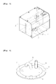
- A fuel tank for a construction machine in the related art, as illustrated in
FIGS. 1 and 2 , includes abaffle plate 2 formed inside thefuel tank 1 to prevent fuel flow during movement of the machine; alower cover 3 mounted on a through hole formed on a bottom surface of the fuel tank to keep sealing without leaking fuel; afuel suction port 4 mounted on thelower cover 3 to communicate with a fuel suction pipe so as to supply the fuel from thefuel tank 1 to an engine side; asuction filter 5 mounted on thefuel suction port 4 to filter contaminants included in the fuel; a diesel heaterfuel suction port 6 mounted on thelower cover 3 to communicate with a diesel heater suction pipe of a line of the fuel that is supplied to a diesel heater which generates heat using a cooling water in the engine and enables a fan in a cab to operate before a work starts in order to improve the work condition in the cab in an extremely cold area; adrain port 7 mounted on thelower cover 3 to discharge the moisture included in the fuel; and afuel return port 8 mounted on the bottom surface in thefuel tank 1 to communicate with a fuel return pipe so as to make the fuel from the engine side return to thefuel tank 1. - During working using an excavator or the like in an extremely cold area, moisture (which may be water drops) may be formed on an inner surface of the
fuel tank 1 that is made of a metal plate due to an external temperature change and may be mixed with the fuel in the fuel tank for a construction machine in the related art. Further, due to the exhaust gas emission regulations of the machine, the temperature of the fuel that returns from the engine side to thefuel tank 1 is further increased, and thus the moisture condensation rate is relatively heightened. Due to this, the high-temperature fuel that returns to thefuel tank 1 through thefuel return port 8 is mixed with the fuel in thefuel tank 1, and in this process, the high-temperature fuel is cooled to cause the moisture to be generated. - Further, since the
fuel return port 8 is positioned adjacent to thefuel suction ports fuel tank 1 through thefuel return port 8 stirs moisture grains that are precipitated on the bottom surface of thefuel tank 1, and thus the moisture that flows in thefuel tank 1 is mixed with the fuel. - In this case, most of the moisture that is mixed with the fuel in the
fuel tank 1 is discharged out of thefuel tank 1 through thedrain port 7. - In contrast, if the engine is in a stop state due to the completion of work, small moisture grains, which freely fall in the
fuel tank 1, may easily flow through an inlet (that is formed to be exposed upwardly) of the dieselheater suction port 6 and may be supplied to the diesel heater. Accordingly, if the engine is not operated for a long time in an extremely cold area (i.e., if the engine is in an off state through the night), the moisture that flows through the diesel heater suction pipe is collected at the lowest position of the diesel heater fuel line and then is frozen to cause the diesel heater to be inoperable. Accordingly, reserved natural ignition of the diesel heater is not performed, and thus the heater function is not performed in the cabin to cause difficulty to an operator. - Therefore, the present invention has been made to solve the above-mentioned problems occurring in the related art, and one subject to be achieved by the present invention is to provide a fuel tank for a construction machine, which can prevent a diesel heater from being inoperable due to an inflow of moisture that is generated due to moisture condensation in the fuel tank into a diesel heater fuel line in the case where the machine is in an engine-off state for a long time in an extremely cold area, and make the moisture within the fuel tank be filtered through a water separator, so that a reserved operation of a diesel heater can be performed smoothly.
- In accordance with an aspect of the present invention, there is provided a fuel tank for a construction machine, which includes a baffle plate formed inside the fuel tank to prevent fuel flow during movement of the machine; a lower cover mounted on a through hole formed on a bottom surface of the fuel tank to keep sealing without leaking fuel; a fuel suction port mounted on the lower cover to communicate with a fuel suction pipe so as to supply the fuel from the fuel tank to an engine side; a suction filter mounted on the fuel suction port to filter contaminants included in the fuel; a diesel heater fuel suction port mounted on the lower cover and having an inlet that is formed to be bent toward the bottom surface of the fuel tank so that moisture, which is generated and dropped within the fuel tank in the case where the machine in an engine-off state is put in an extremely cold area, is prevented from flowing into the inlet and being supplied to a diesel heater suction pipe; a drain port mounted on the lower cover to discharge the moisture included in the fuel; and a fuel return port mounted on the bottom surface in the fuel tank to communicate with a fuel return pipe so as to make the fuel from the engine side return to the fuel tank.
- The fuel tank for a construction machine according to an embodiment of the present invention as described above has the following advantages.
- If the machine is in an engine-off state for a long time in an extremely cold area, the moisture generated within the fuel tank is prevented from flowing into the diesel heater fuel line due to the shape change of the diesel heater fuel suction port in the fuel tank that communicates with the diesel heater suction pipe, and thus smooth operation of the diesel heater can be secured. Further, the moisture that is mixed with the fuel in the fuel tank is filtered through the water separator, and thus the engine can start smoothly.
- The above objects, other features and advantages of the present invention will become more apparent by describing the preferred embodiments thereof with reference to the accompanying drawings, in which:
-
Fig. 1 is a schematic view of a fuel tank for a construction machine in the related art; -
Fig. 2 is a schematic view of a lower cover that is mounted on a bottom surface of a fuel tank for a construction machine in the related art; -
Fig. 3 is a schematic view of a fuel tank for a construction machine according to an embodiment of the present invention; and -
Fig. 4 is a schematic view of a lower cover that is mounted on a bottom surface of a fuel tank for a construction machine according to an embodiment of the present invention. -
- 1: fuel tank
- 2: baffle plate
- 3: lower cover
- 4: fuel suction port
- 5: suction filter
- 7: drain port
- 8: fuel return port
- 9: diesel heater suction port
- Now, a preferred embodiment of the present invention will be described in detail with reference to the accompanying drawings. The matters defined in the description, such as the detailed construction and elements, are nothing but specific details provided to assist those of ordinary skill in the art in a comprehensive understanding of the invention, and the present invention is not limited to the embodiments disclosed hereinafter.
- A fuel tank for a construction machine according to an embodiment of the present invention, as illustrated in
FIGS. 3 and 4 , includes abaffle plate 2 formed inside thefuel tank 1 to prevent fuel flow during movement of the machine; alower cover 3 mounted on a through hole formed on a bottom surface of the fuel tank to keep sealing without leaking fuel; afuel suction port 4 mounted on thelower cover 3 to communicate with a fuel suction pipe (not illustrated) so as to supply the fuel from thefuel tank 1 to an engine side; asuction filter 5 mounted on thefuel suction port 4 to filter contaminants (e.g., contaminants, such as scale and the like) included in the fuel; a diesel heaterfuel suction port 9 mounted on thelower cover 3 and having an inlet that is formed to be bent toward the bottom surface of thefuel tank 1 so that moisture, which is generated and dropped within thefuel tank 1 in the case where the machine in an engine-off state is put in an extremely cold area, is prevented from flowing into the inlet and being supplied to a diesel heater suction pipe; adrain port 7 mounted on thelower cover 3 to discharge the moisture included in the fuel; and afuel return port 8 mounted on the bottom surface in thefuel tank 1 to communicate with a fuel return pipe (not illustrated) so as to make the fuel from the engine side return to thefuel tank 1. - Since the configuration of the
fuel tank 1, except for the diesel heaterfuel suction port 9 mounted on thelower cover 3, is substantially the same as the configuration of the fuel tank illustrated inFIGS. 1 and 2 , the detailed explanation of the configuration and operation thereof will be omitted, and the same reference numerals are used for the same configurations. - Hereinafter, the use example of the fuel tank for a construction machine according to an embodiment of the present invention will be described in detail with reference to the accompanying drawings.
- As illustrated in
FIGS. 3 and 4 , if the machine, such as an excavator, that is in an engine-off state, is put in an extremely cold area over the night after the work using the excavator is completed, moisture is generated in a process in which high-temperature fuel that returns from the engine side to thefuel tank 1 is mixed with the fuel in thefuel tank 1, and due to the difference between the temperature of the fuel and an outdoor temperature, moisture is generated on the inner surface of thefuel tank 1 that is made of a metal material, and is mixed with the fuel in thefuel tank 1. - As described above, even if the machine is in the engine-off state for a long time and the moisture grains, which are generated in the
fuel tank 1, fall freely, the moisture grains can be prevented from flowing into the diesel heater suction pipe. That is, since the inlet of the diesel heaterfuel suction port 9, which is mounted on thelower cover 3 to communicate with the diesel heater suction pipe, is formed to be bent toward the bottom surface of thefuel tank 1, the moisture, which is generated and dropped within thefuel tank 1 due to the condensation thereof, is prevented from flowing into the inlet of the diesel heaterfuel suction port 9. - Accordingly, the moisture that is generated within the
fuel tank 1 is prevented from being supplied to the diesel heater suction pipe through the diesel heaterfuel suction port 9, and thus the diesel heater can be prevented from being inoperable. In this case, since the fuel that is mixed with the moisture in thefuel tank 1 is transported to the water separator through thefuel suction port 4 and the fuel suction pipe, the fuel can be supplied to the engine side after the moisture that is mixed with the fuel is removed through the fuel filter of the water separator. - As apparent from the above description, according to the fuel tank for a construction machine according to the embodiment of the present invention, if the machine is put in an engine-off state in an extremely cold area, the moisture that is generated within the fuel tank is prevented from flowing into the suction pipe of the diesel heater due to the shape change of the diesel heater fuel suction port in the fuel tank, and thus the smooth operation of the diesel heater can be secured. Further, since the moisture in the fuel tank is filtered through the water separator, the reserved operation of the diesel heater can be performed smoothly.
Claims (1)
- A fuel tank for a construction machine comprising:a baffle plate formed inside the fuel tank to prevent fuel flow during movement of the machine;a lower cover mounted on a through hole formed on a bottom surface of the fuel tank to keep sealing without leaking fuel;a fuel suction port mounted on the lower cover to communicate with a fuel suction pipe so as to supply the fuel from the fuel tank to an engine side;a suction filter mounted on the fuel suction port to filter contaminants included in the fuel;a diesel heater fuel suction port mounted on the lower cover and having an inlet that is formed to be bent toward the bottom surface of the fuel tank so that moisture, which is generated and dropped within the fuel tank in the case where the machine in an engine-off state is put in an extremely cold area, is prevented from flowing into the inlet and being supplied to a diesel heater suction pipe;a drain port mounted on the lower cover to discharge the moisture included in the fuel; anda fuel return port mounted on the bottom surface in the fuel tank to communicate with a fuel return pipe so as to make the fuel from the engine side return to the fuel tank.
Applications Claiming Priority (1)
| Application Number | Priority Date | Filing Date | Title |
|---|---|---|---|
| PCT/KR2011/003951 WO2012165668A1 (en) | 2011-05-30 | 2011-05-30 | Fuel tank for heavy construction equipment |
Publications (3)
| Publication Number | Publication Date |
|---|---|
| EP2716484A1 true EP2716484A1 (en) | 2014-04-09 |
| EP2716484A4 EP2716484A4 (en) | 2015-05-20 |
| EP2716484B1 EP2716484B1 (en) | 2016-09-14 |
Family
ID=47259506
Family Applications (1)
| Application Number | Title | Priority Date | Filing Date |
|---|---|---|---|
| EP11866492.9A Active EP2716484B1 (en) | 2011-05-30 | 2011-05-30 | Fuel tank for heavy construction equipment |
Country Status (6)
| Country | Link |
|---|---|
| US (1) | US20140109998A1 (en) |
| EP (1) | EP2716484B1 (en) |
| JP (1) | JP2014523360A (en) |
| KR (1) | KR101734973B1 (en) |
| CN (1) | CN103561985A (en) |
| WO (1) | WO2012165668A1 (en) |
Families Citing this family (5)
| Publication number | Priority date | Publication date | Assignee | Title |
|---|---|---|---|---|
| US10030609B2 (en) | 2015-11-05 | 2018-07-24 | Ini Power Systems, Inc. | Thermal choke, autostart generator system, and method of use thereof |
| US20190101086A1 (en) * | 2017-10-02 | 2019-04-04 | Ini Power Systems, Inc. | Fuel tank |
| JP7115292B2 (en) * | 2018-12-21 | 2022-08-09 | コベルコ建機株式会社 | Fuel tank device for construction machinery and construction machinery |
| JP6964612B2 (en) * | 2019-01-25 | 2021-11-10 | 日立建機株式会社 | Construction machinery |
| JP7219197B2 (en) * | 2019-10-09 | 2023-02-07 | 日立建機株式会社 | WORKING MACHINE FAILURE PREDICTION SYSTEM AND WORKING MACHINE FAILURE PREDICTION METHOD |
Family Cites Families (23)
| Publication number | Priority date | Publication date | Assignee | Title |
|---|---|---|---|---|
| US2262403A (en) * | 1940-05-08 | 1941-11-11 | Westinghouse Electric & Mfg Co | Nonpressure water heater |
| US2614528A (en) * | 1948-04-30 | 1952-10-21 | Craig Corp | Dry spray equipment |
| JPS51106307U (en) * | 1975-02-24 | 1976-08-25 | ||
| JPS61244623A (en) * | 1985-04-22 | 1986-10-30 | Nissan Motor Co Ltd | Fuel takeout structure in fuel tank |
| FR2660280B1 (en) * | 1990-03-27 | 1995-05-05 | Aerospatiale | TANK FOR AIRCRAFT, ESPECIALLY FOR HELICOPTER HYDRAULIC CIRCUIT. |
| JPH06320964A (en) * | 1993-05-18 | 1994-11-22 | Horie Kinzoku Kogyo Kk | Fuel supply device for automobile |
| US5343905A (en) * | 1993-06-07 | 1994-09-06 | Ford Motor Company | Vehicular fuel tank vent |
| US6024246A (en) * | 1998-12-08 | 2000-02-15 | Huang; Hsien-Tu | Structure of squeeze lid |
| JP2000185563A (en) * | 1998-12-22 | 2000-07-04 | Kubota Corp | Engine fuel tank |
| DE50014999D1 (en) * | 2000-05-25 | 2008-04-10 | Dbk David & Baader Gmbh | PTC heater |
| US6953527B2 (en) * | 2003-02-17 | 2005-10-11 | Tecumseh Products Company | Fuel tank with water trap |
| JP4128503B2 (en) * | 2003-08-29 | 2008-07-30 | 本田技研工業株式会社 | Fuel tank |
| KR100602672B1 (en) * | 2004-09-15 | 2006-07-20 | 현대모비스 주식회사 | Device For Removing The Water For Motors And Controlling Method Thereof |
| JP2006316485A (en) * | 2005-05-12 | 2006-11-24 | Shin Caterpillar Mitsubishi Ltd | Operating oil tank for work machine |
| DE102005043818A1 (en) * | 2005-09-13 | 2007-03-22 | Siemens Ag | For sealing an opening of a fuel tank of a motor vehicle provided flange |
| ITRE20050139A1 (en) * | 2005-12-13 | 2007-06-14 | Ufi Filters Spa | DIESEL FUEL FILTER WITH HEATER |
| US7854345B2 (en) * | 2006-05-24 | 2010-12-21 | Cnh America Llc | Vehicular fuel tank arrangement |
| KR100772060B1 (en) * | 2006-06-28 | 2007-11-01 | 볼보 컨스트럭션 이키프먼트 홀딩 스웨덴 에이비 | The fuel supplying system for construction or forestry equipment |
| JP2008265451A (en) * | 2007-04-18 | 2008-11-06 | Honda Motor Co Ltd | Vehicular fuel tank |
| CN201159123Y (en) * | 2007-12-26 | 2008-12-03 | 赵永丰 | Combined fuel tank of diesel locomotive |
| US8191568B2 (en) * | 2008-03-14 | 2012-06-05 | Toyoda Gosei Co., Ltd. | Fuel tank for motor vehicle |
| JP5069277B2 (en) | 2009-08-28 | 2012-11-07 | 日立建機株式会社 | Construction machinery |
| US8485389B2 (en) * | 2011-06-17 | 2013-07-16 | Eaton Corporation | Assembly with vapor vent valve and liquid trap for static leak prevention in vapor control system |
-
2011
- 2011-05-30 WO PCT/KR2011/003951 patent/WO2012165668A1/en active Application Filing
- 2011-05-30 EP EP11866492.9A patent/EP2716484B1/en active Active
- 2011-05-30 KR KR1020137029463A patent/KR101734973B1/en active IP Right Grant
- 2011-05-30 US US14/119,111 patent/US20140109998A1/en not_active Abandoned
- 2011-05-30 JP JP2014513409A patent/JP2014523360A/en active Pending
- 2011-05-30 CN CN201180071178.XA patent/CN103561985A/en active Pending
Also Published As
| Publication number | Publication date |
|---|---|
| US20140109998A1 (en) | 2014-04-24 |
| KR20140010979A (en) | 2014-01-27 |
| EP2716484A4 (en) | 2015-05-20 |
| KR101734973B1 (en) | 2017-05-12 |
| EP2716484B1 (en) | 2016-09-14 |
| JP2014523360A (en) | 2014-09-11 |
| CN103561985A (en) | 2014-02-05 |
| WO2012165668A1 (en) | 2012-12-06 |
Similar Documents
| Publication | Publication Date | Title |
|---|---|---|
| EP2716484A1 (en) | Fuel tank for heavy construction equipment | |
| CN102032025B (en) | Blow-by gas refluxing device | |
| CN101798950B (en) | Cooling system for internal combustion engine | |
| US9675920B2 (en) | Apparatus for air precleaner and precleaner | |
| CN101493029A (en) | Turbocharger and cylinder head | |
| CN203961922U (en) | A kind of taking out type low pressure associated gas recovery device | |
| EP3611356B1 (en) | Cooling circuit of an engine for driving a heat pump compressor | |
| EP2543858B1 (en) | Engine device | |
| CN104265528A (en) | Fuel oil circulating filter system, oil tank and engineering machine | |
| CN204783361U (en) | Engine admit air subassembly and engine system | |
| RU2016121865A (en) | CREATION OF CAPACITY REDUCTION TO REDUCE THE NUMBER OF PARTICLES | |
| JP2013144962A (en) | Water draining device of fuel tank | |
| CN207452979U (en) | Excavator | |
| CN204783362U (en) | Engine admit air subassembly, engine system | |
| CN105339633B (en) | The device and method of the RPM of engine for controlling engineering machinery | |
| CN206707895U (en) | Fuel pipe exhaust apparatus and the engine with fuel pipe exhaust apparatus | |
| CN106286041A (en) | Engine charge assembly, engine system and the method preventing engine air inlet tube inner accumulated berg | |
| CN102330586B (en) | Combustion engine and method for operating combustion engine | |
| CN106065796B (en) | The method of the oil system and operating diesel engine of diesel engine | |
| RU42587U1 (en) | GAS-TURBINE ENGINE OIL SYSTEM | |
| CN105370340B (en) | Utilize the engine motor oil preheating structure of air compressor | |
| CN103244314A (en) | Power system, engineering machinery and engine air replenishing method | |
| JP2014066203A (en) | Fuel supply system | |
| CN213388522U (en) | Energy-saving circulation heating petroleum gathering and transportation device | |
| JP5296582B2 (en) | Engine generator |
Legal Events
| Date | Code | Title | Description |
|---|---|---|---|
| PUAI | Public reference made under article 153(3) epc to a published international application that has entered the european phase |
Free format text: ORIGINAL CODE: 0009012 |
|
| 17P | Request for examination filed |
Effective date: 20131120 |
|
| AK | Designated contracting states |
Kind code of ref document: A1 Designated state(s): AL AT BE BG CH CY CZ DE DK EE ES FI FR GB GR HR HU IE IS IT LI LT LU LV MC MK MT NL NO PL PT RO RS SE SI SK SM TR |
|
| DAX | Request for extension of the european patent (deleted) | ||
| RA4 | Supplementary search report drawn up and despatched (corrected) |
Effective date: 20150420 |
|
| RIC1 | Information provided on ipc code assigned before grant |
Ipc: E02F 9/00 20060101ALI20150414BHEP Ipc: B60K 15/03 20060101AFI20150414BHEP |
|
| GRAP | Despatch of communication of intention to grant a patent |
Free format text: ORIGINAL CODE: EPIDOSNIGR1 |
|
| INTG | Intention to grant announced |
Effective date: 20160429 |
|
| GRAS | Grant fee paid |
Free format text: ORIGINAL CODE: EPIDOSNIGR3 |
|
| GRAA | (expected) grant |
Free format text: ORIGINAL CODE: 0009210 |
|
| AK | Designated contracting states |
Kind code of ref document: B1 Designated state(s): AL AT BE BG CH CY CZ DE DK EE ES FI FR GB GR HR HU IE IS IT LI LT LU LV MC MK MT NL NO PL PT RO RS SE SI SK SM TR |
|
| REG | Reference to a national code |
Ref country code: GB Ref legal event code: FG4D |
|
| REG | Reference to a national code |
Ref country code: CH Ref legal event code: EP |
|
| REG | Reference to a national code |
Ref country code: IE Ref legal event code: FG4D |
|
| REG | Reference to a national code |
Ref country code: AT Ref legal event code: REF Ref document number: 828550 Country of ref document: AT Kind code of ref document: T Effective date: 20161015 |
|
| REG | Reference to a national code |
Ref country code: DE Ref legal event code: R096 Ref document number: 602011030456 Country of ref document: DE |
|
| REG | Reference to a national code |
Ref country code: LT Ref legal event code: MG4D |
|
| REG | Reference to a national code |
Ref country code: NL Ref legal event code: MP Effective date: 20160914 |
|
| PG25 | Lapsed in a contracting state [announced via postgrant information from national office to epo] |
Ref country code: HR Free format text: LAPSE BECAUSE OF FAILURE TO SUBMIT A TRANSLATION OF THE DESCRIPTION OR TO PAY THE FEE WITHIN THE PRESCRIBED TIME-LIMIT Effective date: 20160914 Ref country code: NO Free format text: LAPSE BECAUSE OF FAILURE TO SUBMIT A TRANSLATION OF THE DESCRIPTION OR TO PAY THE FEE WITHIN THE PRESCRIBED TIME-LIMIT Effective date: 20161214 Ref country code: FI Free format text: LAPSE BECAUSE OF FAILURE TO SUBMIT A TRANSLATION OF THE DESCRIPTION OR TO PAY THE FEE WITHIN THE PRESCRIBED TIME-LIMIT Effective date: 20160914 Ref country code: RS Free format text: LAPSE BECAUSE OF FAILURE TO SUBMIT A TRANSLATION OF THE DESCRIPTION OR TO PAY THE FEE WITHIN THE PRESCRIBED TIME-LIMIT Effective date: 20160914 Ref country code: LT Free format text: LAPSE BECAUSE OF FAILURE TO SUBMIT A TRANSLATION OF THE DESCRIPTION OR TO PAY THE FEE WITHIN THE PRESCRIBED TIME-LIMIT Effective date: 20160914 |
|
| REG | Reference to a national code |
Ref country code: AT Ref legal event code: MK05 Ref document number: 828550 Country of ref document: AT Kind code of ref document: T Effective date: 20160914 |
|
| PG25 | Lapsed in a contracting state [announced via postgrant information from national office to epo] |
Ref country code: NL Free format text: LAPSE BECAUSE OF FAILURE TO SUBMIT A TRANSLATION OF THE DESCRIPTION OR TO PAY THE FEE WITHIN THE PRESCRIBED TIME-LIMIT Effective date: 20160914 Ref country code: LV Free format text: LAPSE BECAUSE OF FAILURE TO SUBMIT A TRANSLATION OF THE DESCRIPTION OR TO PAY THE FEE WITHIN THE PRESCRIBED TIME-LIMIT Effective date: 20160914 Ref country code: GR Free format text: LAPSE BECAUSE OF FAILURE TO SUBMIT A TRANSLATION OF THE DESCRIPTION OR TO PAY THE FEE WITHIN THE PRESCRIBED TIME-LIMIT Effective date: 20161215 Ref country code: SE Free format text: LAPSE BECAUSE OF FAILURE TO SUBMIT A TRANSLATION OF THE DESCRIPTION OR TO PAY THE FEE WITHIN THE PRESCRIBED TIME-LIMIT Effective date: 20160914 |
|
| PG25 | Lapsed in a contracting state [announced via postgrant information from national office to epo] |
Ref country code: EE Free format text: LAPSE BECAUSE OF FAILURE TO SUBMIT A TRANSLATION OF THE DESCRIPTION OR TO PAY THE FEE WITHIN THE PRESCRIBED TIME-LIMIT Effective date: 20160914 Ref country code: RO Free format text: LAPSE BECAUSE OF FAILURE TO SUBMIT A TRANSLATION OF THE DESCRIPTION OR TO PAY THE FEE WITHIN THE PRESCRIBED TIME-LIMIT Effective date: 20160914 |
|
| REG | Reference to a national code |
Ref country code: FR Ref legal event code: PLFP Year of fee payment: 7 |
|
| PG25 | Lapsed in a contracting state [announced via postgrant information from national office to epo] |
Ref country code: AT Free format text: LAPSE BECAUSE OF FAILURE TO SUBMIT A TRANSLATION OF THE DESCRIPTION OR TO PAY THE FEE WITHIN THE PRESCRIBED TIME-LIMIT Effective date: 20160914 Ref country code: IS Free format text: LAPSE BECAUSE OF FAILURE TO SUBMIT A TRANSLATION OF THE DESCRIPTION OR TO PAY THE FEE WITHIN THE PRESCRIBED TIME-LIMIT Effective date: 20170114 Ref country code: ES Free format text: LAPSE BECAUSE OF FAILURE TO SUBMIT A TRANSLATION OF THE DESCRIPTION OR TO PAY THE FEE WITHIN THE PRESCRIBED TIME-LIMIT Effective date: 20160914 Ref country code: SM Free format text: LAPSE BECAUSE OF FAILURE TO SUBMIT A TRANSLATION OF THE DESCRIPTION OR TO PAY THE FEE WITHIN THE PRESCRIBED TIME-LIMIT Effective date: 20160914 Ref country code: PT Free format text: LAPSE BECAUSE OF FAILURE TO SUBMIT A TRANSLATION OF THE DESCRIPTION OR TO PAY THE FEE WITHIN THE PRESCRIBED TIME-LIMIT Effective date: 20170116 Ref country code: BE Free format text: LAPSE BECAUSE OF FAILURE TO SUBMIT A TRANSLATION OF THE DESCRIPTION OR TO PAY THE FEE WITHIN THE PRESCRIBED TIME-LIMIT Effective date: 20160914 Ref country code: CZ Free format text: LAPSE BECAUSE OF FAILURE TO SUBMIT A TRANSLATION OF THE DESCRIPTION OR TO PAY THE FEE WITHIN THE PRESCRIBED TIME-LIMIT Effective date: 20160914 Ref country code: BG Free format text: LAPSE BECAUSE OF FAILURE TO SUBMIT A TRANSLATION OF THE DESCRIPTION OR TO PAY THE FEE WITHIN THE PRESCRIBED TIME-LIMIT Effective date: 20161214 Ref country code: PL Free format text: LAPSE BECAUSE OF FAILURE TO SUBMIT A TRANSLATION OF THE DESCRIPTION OR TO PAY THE FEE WITHIN THE PRESCRIBED TIME-LIMIT Effective date: 20160914 Ref country code: SK Free format text: LAPSE BECAUSE OF FAILURE TO SUBMIT A TRANSLATION OF THE DESCRIPTION OR TO PAY THE FEE WITHIN THE PRESCRIBED TIME-LIMIT Effective date: 20160914 |
|
| REG | Reference to a national code |
Ref country code: DE Ref legal event code: R097 Ref document number: 602011030456 Country of ref document: DE |
|
| PG25 | Lapsed in a contracting state [announced via postgrant information from national office to epo] |
Ref country code: IT Free format text: LAPSE BECAUSE OF FAILURE TO SUBMIT A TRANSLATION OF THE DESCRIPTION OR TO PAY THE FEE WITHIN THE PRESCRIBED TIME-LIMIT Effective date: 20160914 |
|
| PLBE | No opposition filed within time limit |
Free format text: ORIGINAL CODE: 0009261 |
|
| STAA | Information on the status of an ep patent application or granted ep patent |
Free format text: STATUS: NO OPPOSITION FILED WITHIN TIME LIMIT |
|
| PG25 | Lapsed in a contracting state [announced via postgrant information from national office to epo] |
Ref country code: DK Free format text: LAPSE BECAUSE OF FAILURE TO SUBMIT A TRANSLATION OF THE DESCRIPTION OR TO PAY THE FEE WITHIN THE PRESCRIBED TIME-LIMIT Effective date: 20160914 |
|
| 26N | No opposition filed |
Effective date: 20170615 |
|
| PG25 | Lapsed in a contracting state [announced via postgrant information from national office to epo] |
Ref country code: LU Free format text: LAPSE BECAUSE OF NON-PAYMENT OF DUE FEES Effective date: 20170531 |
|
| PG25 | Lapsed in a contracting state [announced via postgrant information from national office to epo] |
Ref country code: SI Free format text: LAPSE BECAUSE OF FAILURE TO SUBMIT A TRANSLATION OF THE DESCRIPTION OR TO PAY THE FEE WITHIN THE PRESCRIBED TIME-LIMIT Effective date: 20160914 |
|
| REG | Reference to a national code |
Ref country code: CH Ref legal event code: PL |
|
| PG25 | Lapsed in a contracting state [announced via postgrant information from national office to epo] |
Ref country code: MC Free format text: LAPSE BECAUSE OF FAILURE TO SUBMIT A TRANSLATION OF THE DESCRIPTION OR TO PAY THE FEE WITHIN THE PRESCRIBED TIME-LIMIT Effective date: 20160914 |
|
| REG | Reference to a national code |
Ref country code: IE Ref legal event code: MM4A |
|
| PG25 | Lapsed in a contracting state [announced via postgrant information from national office to epo] |
Ref country code: CH Free format text: LAPSE BECAUSE OF NON-PAYMENT OF DUE FEES Effective date: 20170531 Ref country code: LI Free format text: LAPSE BECAUSE OF NON-PAYMENT OF DUE FEES Effective date: 20170531 |
|
| PG25 | Lapsed in a contracting state [announced via postgrant information from national office to epo] |
Ref country code: LU Free format text: LAPSE BECAUSE OF NON-PAYMENT OF DUE FEES Effective date: 20170530 |
|
| PG25 | Lapsed in a contracting state [announced via postgrant information from national office to epo] |
Ref country code: IE Free format text: LAPSE BECAUSE OF NON-PAYMENT OF DUE FEES Effective date: 20170530 |
|
| REG | Reference to a national code |
Ref country code: FR Ref legal event code: PLFP Year of fee payment: 8 |
|
| PG25 | Lapsed in a contracting state [announced via postgrant information from national office to epo] |
Ref country code: MT Free format text: LAPSE BECAUSE OF NON-PAYMENT OF DUE FEES Effective date: 20170530 |
|
| PG25 | Lapsed in a contracting state [announced via postgrant information from national office to epo] |
Ref country code: AL Free format text: LAPSE BECAUSE OF FAILURE TO SUBMIT A TRANSLATION OF THE DESCRIPTION OR TO PAY THE FEE WITHIN THE PRESCRIBED TIME-LIMIT Effective date: 20160914 |
|
| REG | Reference to a national code |
Ref country code: DE Ref legal event code: R082 Ref document number: 602011030456 Country of ref document: DE Representative=s name: EPPING HERMANN FISCHER PATENTANWALTSGESELLSCHA, DE |
|
| PG25 | Lapsed in a contracting state [announced via postgrant information from national office to epo] |
Ref country code: HU Free format text: LAPSE BECAUSE OF FAILURE TO SUBMIT A TRANSLATION OF THE DESCRIPTION OR TO PAY THE FEE WITHIN THE PRESCRIBED TIME-LIMIT; INVALID AB INITIO Effective date: 20110530 |
|
| PG25 | Lapsed in a contracting state [announced via postgrant information from national office to epo] |
Ref country code: CY Free format text: LAPSE BECAUSE OF NON-PAYMENT OF DUE FEES Effective date: 20160914 |
|
| PG25 | Lapsed in a contracting state [announced via postgrant information from national office to epo] |
Ref country code: MK Free format text: LAPSE BECAUSE OF FAILURE TO SUBMIT A TRANSLATION OF THE DESCRIPTION OR TO PAY THE FEE WITHIN THE PRESCRIBED TIME-LIMIT Effective date: 20160914 |
|
| PG25 | Lapsed in a contracting state [announced via postgrant information from national office to epo] |
Ref country code: TR Free format text: LAPSE BECAUSE OF FAILURE TO SUBMIT A TRANSLATION OF THE DESCRIPTION OR TO PAY THE FEE WITHIN THE PRESCRIBED TIME-LIMIT Effective date: 20160914 |
|
| PGFP | Annual fee paid to national office [announced via postgrant information from national office to epo] |
Ref country code: FR Payment date: 20230523 Year of fee payment: 13 Ref country code: DE Payment date: 20230530 Year of fee payment: 13 |
|
| PGFP | Annual fee paid to national office [announced via postgrant information from national office to epo] |
Ref country code: GB Payment date: 20230523 Year of fee payment: 13 |