JP5069277B2 - Construction machinery - Google Patents
Construction machinery Download PDFInfo
- Publication number
- JP5069277B2 JP5069277B2 JP2009198122A JP2009198122A JP5069277B2 JP 5069277 B2 JP5069277 B2 JP 5069277B2 JP 2009198122 A JP2009198122 A JP 2009198122A JP 2009198122 A JP2009198122 A JP 2009198122A JP 5069277 B2 JP5069277 B2 JP 5069277B2
- Authority
- JP
- Japan
- Prior art keywords
- fuel
- fuel tank
- flexible hose
- shape
- supply pipe
- Prior art date
- Legal status (The legal status is an assumption and is not a legal conclusion. Google has not performed a legal analysis and makes no representation as to the accuracy of the status listed.)
- Expired - Fee Related
Links
Images


Classifications
-
- B—PERFORMING OPERATIONS; TRANSPORTING
- B60—VEHICLES IN GENERAL
- B60K—ARRANGEMENT OR MOUNTING OF PROPULSION UNITS OR OF TRANSMISSIONS IN VEHICLES; ARRANGEMENT OR MOUNTING OF PLURAL DIVERSE PRIME-MOVERS IN VEHICLES; AUXILIARY DRIVES FOR VEHICLES; INSTRUMENTATION OR DASHBOARDS FOR VEHICLES; ARRANGEMENTS IN CONNECTION WITH COOLING, AIR INTAKE, GAS EXHAUST OR FUEL SUPPLY OF PROPULSION UNITS IN VEHICLES
- B60K15/00—Arrangement in connection with fuel supply of combustion engines or other fuel consuming energy converters, e.g. fuel cells; Mounting or construction of fuel tanks
- B60K15/01—Arrangement of fuel conduits
-
- B—PERFORMING OPERATIONS; TRANSPORTING
- B60—VEHICLES IN GENERAL
- B60K—ARRANGEMENT OR MOUNTING OF PROPULSION UNITS OR OF TRANSMISSIONS IN VEHICLES; ARRANGEMENT OR MOUNTING OF PLURAL DIVERSE PRIME-MOVERS IN VEHICLES; AUXILIARY DRIVES FOR VEHICLES; INSTRUMENTATION OR DASHBOARDS FOR VEHICLES; ARRANGEMENTS IN CONNECTION WITH COOLING, AIR INTAKE, GAS EXHAUST OR FUEL SUPPLY OF PROPULSION UNITS IN VEHICLES
- B60K15/00—Arrangement in connection with fuel supply of combustion engines or other fuel consuming energy converters, e.g. fuel cells; Mounting or construction of fuel tanks
- B60K15/03—Fuel tanks
-
- E—FIXED CONSTRUCTIONS
- E02—HYDRAULIC ENGINEERING; FOUNDATIONS; SOIL SHIFTING
- E02F—DREDGING; SOIL-SHIFTING
- E02F9/00—Component parts of dredgers or soil-shifting machines, not restricted to one of the kinds covered by groups E02F3/00 - E02F7/00
- E02F9/08—Superstructures; Supports for superstructures
- E02F9/0858—Arrangement of component parts installed on superstructures not otherwise provided for, e.g. electric components, fenders, air-conditioning units
- E02F9/0883—Tanks, e.g. oil tank, urea tank, fuel tank
-
- E—FIXED CONSTRUCTIONS
- E02—HYDRAULIC ENGINEERING; FOUNDATIONS; SOIL SHIFTING
- E02F—DREDGING; SOIL-SHIFTING
- E02F9/00—Component parts of dredgers or soil-shifting machines, not restricted to one of the kinds covered by groups E02F3/00 - E02F7/00
- E02F9/18—Counterweights
Description
本発明は、例えば油圧ショベル等の建設機械に関し、特に、車体に燃料タンクを搭載した建設機械に関する。 The present invention relates to a construction machine such as a hydraulic excavator, and more particularly to a construction machine in which a fuel tank is mounted on a vehicle body.
一般に、建設機械の代表例である油圧ショベルは、下部走行体および上部旋回体からなる車体を備えると共に、該車体には、駆動源となるエンジンや、燃料を貯留する燃料タンク等が搭載されている。この燃料タンクの底面には、エンジンに向けて燃料を供給する燃料供給配管が接続されている。また、建設機械は、平坦地に限らず、傾斜地でも作業が行われる。この傾斜地では燃料タンクも傾くため、燃料タンク内に開口した燃料供給配管の開口端が燃料の液面よりも高い位置に配置されて、燃料供給配管から全ての燃料を送り出すことができないことがある。このため、燃料供給配管の先端にスイベルジョイントを介して回転可能な吸込管を接続した構成が知られている(例えば、特許文献1参照)。この場合、吸込管の先端が燃料供給配管の先端よりも下方側に配置されるから、燃料供給配管の先端よりも下方側に位置する燃料も送出可能になっている。 In general, a hydraulic excavator, which is a typical example of a construction machine, includes a vehicle body including a lower traveling body and an upper swing body, and an engine serving as a driving source, a fuel tank that stores fuel, and the like are mounted on the vehicle body. Yes. A fuel supply pipe for supplying fuel toward the engine is connected to the bottom surface of the fuel tank. In addition, construction machines are not limited to flat ground, and work is also performed on sloping ground. Since the fuel tank also inclines on this slope, the open end of the fuel supply pipe opened in the fuel tank is arranged at a position higher than the liquid level of the fuel, and it may not be possible to send out all the fuel from the fuel supply pipe. . For this reason, the structure which connected the suction pipe which can rotate through the swivel joint to the front-end | tip of fuel supply piping is known (for example, refer patent document 1). In this case, since the tip of the suction pipe is disposed below the tip of the fuel supply pipe, the fuel positioned below the tip of the fuel supply pipe can also be sent out.
ところで、上述した特許文献1による油圧ショベルでは、スイベルジョイントを用いて吸込管を回転可能に取り付けているから、燃料タンクの底面を円形に形成した場合には、燃料タンクが傾いたときでも、ほぼ全ての燃料を燃料供給配管から送り出すことができる。しかし、例えばミニショベルのように、旋回体上の設置範囲が極めて狭く、かつ空間に制約がある場合、燃料タンクの底面が、四角形、楕円形等のように回転非対称な形状に形成されることが多い。この場合には、吸込管の先端が燃料の液面から離れることがあり、燃料タンクの角隅側に片寄った燃料を送り出すことができないという問題がある。
By the way, in the hydraulic excavator according to
特に、例えば上部旋回体の旋回フレームが下部走行体の幅内に入るように形成したミニショベルのうちの小旋回型の建設機械では、燃料タンクの設置空間を確保するのが難しい。このため、燃料タンクは、上部旋回体の外形形状に沿うように、例えば旋回円に沿って細長い円弧状に形成されることがある。この場合、燃料タンクの底面は、縦方向と横方向で長さ寸法が大きく異なる細長い形状となるから、吸込管の先端が届かない範囲が増加して、送り出すことができない燃料が増加する傾向がある。 In particular, it is difficult to secure an installation space for the fuel tank in a small turning type construction machine of a mini excavator formed so that the turning frame of the upper turning body falls within the width of the lower traveling body. For this reason, the fuel tank may be formed in an elongated arc shape along the turning circle, for example, along the outer shape of the upper turning body. In this case, the bottom surface of the fuel tank has a long and narrow shape that differs greatly in length in the vertical direction and in the horizontal direction. Therefore, the range in which the tip of the suction pipe does not reach increases and the amount of fuel that cannot be delivered tends to increase. is there.
本発明は上述した従来技術の問題に鑑みなされたもので、本発明の目的は、任意形状の燃料タンクが傾いたときでも、端部側に位置する燃料を送り出すことができる建設機械を提供することにある。 The present invention has been made in view of the above-described problems of the prior art, and an object of the present invention is to provide a construction machine capable of delivering fuel located on the end side even when an arbitrarily shaped fuel tank is tilted. There is.
上述した課題を解決するために、本発明は、エンジンを搭載した車体と、該車体に設けられ前記エンジンに供給するための燃料を貯える燃料タンクと、該燃料タンクに接続された燃料供給配管とを備え、前記燃料供給配管は前記燃料タンクの底面に接続して設け、前記燃料タンク内には基端側が前記燃料供給配管に接続された可撓性ホースを設け、該可撓性ホースの先端側には燃料タンクの底面に当接する状態で沈降する錘部材を設け、該錘部材には前記可撓性ホースを通じて前記燃料供給配管に連通する吸込口を設けてなる建設機械に適用される。 In order to solve the above-described problems, the present invention provides a vehicle body on which an engine is mounted, a fuel tank that is provided in the vehicle body and stores fuel to be supplied to the engine, and a fuel supply pipe connected to the fuel tank. The fuel supply pipe is connected to the bottom surface of the fuel tank, a flexible hose having a proximal end connected to the fuel supply pipe is provided in the fuel tank, and the distal end of the flexible hose A weight member that sinks in contact with the bottom surface of the fuel tank is provided on the side, and the weight member is applied to a construction machine having a suction port that communicates with the fuel supply pipe through the flexible hose .
そして、請求項1の発明が採用する構成の特徴は、前記可撓性ホースは、基端側が前記燃料供給配管に接続されて上側に向けて延び、長さ方向の中間部分が逆U字状に湾曲し、先端側が該中間部分から下側に向けて延びて前記錘部材に取付けられる構成とし、前記錘部材は外形が球形状、卵形状、水滴形状または楕円体形状をなす球体部材からなり、該球体部材には、前記吸込口を複数箇所に開口して設け、前記球体部材には、その外表面よりも外側に突出して前記可撓性ホースに接続されると共に前記吸込口に連通する接続口を設ける構成としたことにある。
A feature of the configuration adopted by the invention of
請求項2の発明では、前記吸込口は、前記球体部材の外表面のうち該接続口とは反対側の球面のいずれかの位置に開口する構成としている。
請求項3の発明では、前記吸込口には燃料フィルタを取り付ける構成としている。
In the invention of
According to a third aspect of the present invention, a fuel filter is attached to the suction port.
請求項4の発明では、前記車体は、クローラ式の下部走行体と、該下部走行体上に旋回可能に設けられ旋回動作したときに周囲の障害物に衝突しないように上側からみてほぼ円形状に形成された上部旋回体とによって形成され、前記上部旋回体の前側には、土砂の掘削作業を行う作業装置が俯仰動可能に設けられ、前記上部旋回体は、支持構造体を構成する旋回フレームと、該旋回フレームの左前側に設けられオペレータが搭乗するキャブと、前記旋回フレームの後側に横置き状態で搭載され油圧ポンプを駆動する前記エンジンと、前記旋回フレームの後部に取付けられ前記作業装置との重量バランスをとるカウンタウエイトと、前記キャブの右側に位置して前記旋回フレーム上に設けられた作動油タンクおよび前記燃料タンクと、前記エンジン、前記作動油タンクおよび前記燃料タンクを覆うように前記旋回フレーム上に設けられた建屋カバーとを備え、前記燃料タンクは、前記旋回フレームの右側の外側寄りに配設されると共に、その底面は左,右方向の寸法よりも前,後方向の寸法が大きな細長い形状に形成され、前記燃料供給配管は、前記燃料タンクの底面に取付けられたコネクタと、該コネクタに接続され前記エンジンに燃料を供給するための燃料ホースとによって構成され、前記コネクタは、前記燃料タンクの底面の中央部分に配置され、前記コネクタには、前記燃料タンク内で前記可撓性ホースが接続される構成としている。 According to a fourth aspect of the present invention, the vehicle body is substantially circular when viewed from above so as not to collide with a surrounding obstacle when the crawler-type lower traveling body and the lower traveling body are provided so as to be able to turn and turn. And a work device for excavating earth and sand is provided on the front side of the upper swing body so as to be able to move up and down. The upper swing body is a swing that constitutes a support structure. A frame, a cab that is provided on the left front side of the swivel frame and on which an operator rides, the engine that is mounted horizontally on the rear side of the swivel frame and that drives a hydraulic pump, and is attached to a rear portion of the swivel frame and is A counterweight that balances the weight with the working device, a hydraulic oil tank and a fuel tank that are located on the right side of the cab and provided on the revolving frame, and the engine And a building cover provided on the revolving frame so as to cover the hydraulic oil tank and the fuel tank, and the fuel tank is disposed on the outer side of the right side of the revolving frame and has a bottom surface Is formed in an elongated shape with dimensions larger in the front and rear directions than the dimensions in the left and right directions, and the fuel supply pipe is connected to the bottom surface of the fuel tank, and the fuel connected to the connector is connected to the engine. The connector is arranged at a central portion of the bottom surface of the fuel tank, and the connector is connected to the flexible hose within the fuel tank. .
請求項1の発明によれば、可撓性ホースの先端側には燃料タンクの底面に当接する状態で沈降する錘部材を設けたから、錘部材を燃料中に沈めることができ、錘部材の吸込口から燃料を吸込むことができる。また、錘部材と燃料供給配管との間を可撓性ホースを用いて接続したから、錘部材は可撓性ホースが届く範囲内で燃料タンク内を自由に移動することができる。そして、燃料タンクが傾いたときには、燃料タンク内の最も低い位置に錘部材が移動する。このため、燃料タンクの角隅側に燃料が片寄るときでも、この燃料中に錘部材を沈めて吸込口から燃料を吸込むことができ、ほぼ全ての燃料を燃料供給配管に送り出すことができる。 According to the first aspect of the present invention, since the weight member that sinks while being in contact with the bottom surface of the fuel tank is provided on the distal end side of the flexible hose, the weight member can be submerged in the fuel, and the suction of the weight member Fuel can be sucked from the mouth. Further, since the weight member and the fuel supply pipe are connected using the flexible hose, the weight member can freely move in the fuel tank within the reach of the flexible hose. When the fuel tank is tilted, the weight member moves to the lowest position in the fuel tank. For this reason, even when the fuel is shifted to the corner of the fuel tank, the weight member can be submerged in the fuel and the fuel can be sucked from the suction port, and almost all the fuel can be sent to the fuel supply pipe.
また、可撓性ホースは長さ方向の中間部分が逆U字状に湾曲する構成とした。このため、可撓性ホースの基端側を燃料タンクの底面に接続された燃料供給配管に接続することができると共に、可撓性ホースの先端側を下側に向けて延ばして錘部材を燃料中に沈めることができ、錘部材の吸込口から燃料を吸込むことができる。
さらに、球体部材にはその外表面よりも外側に突出した接続口を設け、該接続口に可撓性ホースを接続する構成としたから、球体部材の接続口は可撓性ホースに引っ張られて上側に配置することができる。
これに加えて、錘部材は外形が球形状、卵形状、水滴形状または楕円体形状をなす球体部材によって構成したから、燃料タンク内に凹凸部分がある場合でも、球体部材はこの凹凸部分を容易に乗り越えることができ、任意形状の燃料タンク内で球体部材を最も低い位置に移動させることができる。また、球体部材には吸込口を複数箇所に開口して設けたから、例えば1つの吸込口が燃料タンクの底面や壁面で塞がれるときでも、他の吸込口を通じて燃料を吸込むことができる。
In addition, the flexible hose has a configuration in which an intermediate portion in the length direction is curved in an inverted U shape. For this reason, the base end side of the flexible hose can be connected to the fuel supply pipe connected to the bottom surface of the fuel tank, and the tip end side of the flexible hose is extended downward to make the weight member a fuel. The fuel can be sucked in from the suction port of the weight member.
Further, since the spherical member is provided with a connection port protruding outward from the outer surface thereof, and the flexible hose is connected to the connection port, the connection port of the spherical member is pulled by the flexible hose. It can be arranged on the upper side.
In addition to this, since the weight member is constituted by a spherical member whose outer shape is spherical , egg-shaped, water droplet-shaped or ellipsoidal, even when there is an uneven portion in the fuel tank, the spherical member can easily make this uneven portion. The spherical member can be moved to the lowest position in a fuel tank of an arbitrary shape. In addition, since the spherical member is provided with a plurality of suction openings, fuel can be sucked through the other suction openings even when, for example, one suction opening is blocked by the bottom or wall surface of the fuel tank.
請求項2の発明によれば、吸込口は球体部材の外表面のうち接続口とは反対側の球面のいずれかの位置に開口するから、球体部材の接続口が可撓性ホースに引っ張られて上側に位置するのに対して、吸込口は球体部材の中心よりも下側に配置される。このため、球体部材の一部が燃料の液面よりも上側に位置するときでも、吸込口を燃料中に配置することができ、吸込口が液面から露出するのを防止することができる。
請求項3の発明によれば、吸込口には燃料フィルタを取り付けるから、燃料フィルタによって燃料をろ過することができ、燃料中の塵埃が可撓性ホース内に進入するのを防止し、可撓性ホースの目詰まりや流路断面積の減少を防止することができる。
According to the invention of
According to the invention of claim 3, since the fuel filter is attached to the suction port, the fuel can be filtered by the fuel filter, and the dust in the fuel is prevented from entering the flexible hose and is flexible. The hose can be prevented from being clogged and the flow path cross-sectional area being reduced.
請求項4の発明によれば、上部旋回体は上側からみてほぼ円形状に形成されると共に、燃料タンクは旋回フレームの右側の外側寄りに配設され、燃料タンクの底面は左,右方向の寸法よりも前,後方向の寸法が大きな細長い形状に形成される。このとき、燃料供給配管のコネクタは、燃料タンクの底面の中央部分に配置されると共に、このコネクタには可撓性ホースが接続される構成とした。このため、可撓性ホースの先端側に錘部材を設けることによって、燃料タンクの底面が細長い形状をなしているときでも、燃料タンクの最も低い位置に錘部材を移動させることができる。この結果、錘部材を燃料が溜まる位置に確実に移動させることができ、錘部材の吸込口を通じてほぼ全ての燃料を吸込むことができる。 According to the invention of claim 4 , the upper revolving structure is formed in a substantially circular shape when viewed from the upper side, the fuel tank is disposed on the outer side on the right side of the revolving frame, and the bottom surface of the fuel tank is in the left and right directions. It is formed in a long and narrow shape with dimensions larger in the front and rear directions than the dimensions. At this time, the connector of the fuel supply pipe is arranged at the center portion of the bottom surface of the fuel tank, and a flexible hose is connected to this connector. For this reason, by providing the weight member on the distal end side of the flexible hose, the weight member can be moved to the lowest position of the fuel tank even when the bottom surface of the fuel tank has an elongated shape. As a result, the weight member can be reliably moved to a position where fuel is accumulated, and almost all fuel can be sucked through the suction port of the weight member.
以下、本発明の実施の形態による建設機械として油圧ショベルを例に挙げ、添付図面に従って詳細に説明する。 Hereinafter, a hydraulic excavator will be exemplified as a construction machine according to an embodiment of the present invention and will be described in detail with reference to the accompanying drawings.
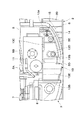
まず、図1ないし図12は本発明の第1の実施の形態を示している。図において、1は建設機械としての油圧ショベルを示し、この油圧ショベル1は、自走可能なクローラ式の下部走行体2と、該下部走行体2上に旋回可能に搭載され該下部走行体2と共に車体を構成する上部旋回体3と、該上部旋回体3の前側に俯仰動可能に設けられ、土砂の掘削作業等を行う作業装置4とにより大略構成されている。
First, FIGS. 1 to 12 show a first embodiment of the present invention. In the figure,
また、下部走行体2は、図1、図2に示すように、トラックフレーム2Aの左,右両側に位置して前,後に離間した遊動輪2Bと駆動輪2C(図1中に右側のみ図示)を有し、該遊動輪2Bと駆動輪2Cには履帯2Dが巻回されている。ここで、下部走行体2は、左,右の履帯2Dの外側端縁間の距離が車幅となっている。
Further, as shown in FIGS. 1 and 2, the
また、作業装置4は、旋回フレーム5の前部に左,右方向に揺動可能に取付けられたスイングポスト4Aと、該スイングポスト4Aに俯仰動可能に取付けられたブーム4Bと、該ブーム4Bの先端部に回動可能に取付けられたアーム4Cと、該アーム4Cの先端部に回動可能に取付けられたバケット4Dと、これらを駆動するブームシリンダ4E、アームシリンダ4F、バケットシリンダ4G等により構成されている。
Further, the working device 4 includes a
さらに、下部走行体2上に旋回可能に搭載された上部旋回体3は、旋回動作したときに周囲の障害物に衝突しないように、上側からみてほぼ円形状に形成されている。そして、上部旋回体3は、図1、図2に示すように、支持構造体を構成すると共に前部に作業装置4のスイングポスト4Aが取付けられた旋回フレーム5と、該旋回フレーム5の左前側に設けられオペレータが搭乗するキャブ6と、旋回フレーム5の後側に横置き状態で搭載され油圧ポンプ7Aを駆動するエンジン7と、該エンジン7の右側に設けられたラジエータ、オイルクーラ等の熱交換器8と、旋回フレーム5の後部に取付けられ作業装置4との重量バランスをとるカウンタウエイト9と、キャブ6の右側に位置して旋回フレーム5上に設けられた後述の作動油タンク11、燃料タンク13と、これらの機器を覆うように旋回フレーム5上に設けられた建屋カバー10とにより大略構成されている。
Furthermore, the upper revolving structure 3 mounted on the
また、旋回フレーム5は、図2、図3に示すように、底板5Aと、該底板5Aに前,後方向に延びて立設された左,右の縦板5B(右側のみ図示)と、左,右両側に設けられ円弧状に湾曲した左サイドフレーム5C,右サイドフレーム5Dとにより大略構成されている。ここで、旋回中心Oを中心にして旋回動作したときに下部走行体2の車幅からはみ出さない範囲を円弧Sとする。これに対し、キャブ6と左,右方向の反対側に位置する右サイドフレーム5Dは、前側側面5Eが円弧S内に入るように円弧形状に形成されている。これにより、前側を障害物に接近させて作業を行う場合でも、キャブ6から遠く見え難い右側部分が障害物に干渉しないか気にすることなく作業を行うことができる。
Further, as shown in FIGS. 2 and 3, the revolving
一方、建屋カバー10は、カウンタウエイト9の前側に位置してエンジン7等を覆うエンジンカバー10Aと、キャブ6の右側に設けられ、作動油タンク11、燃料タンク13等を覆うタンクカバー10Bとにより大略構成されている。また、タンクカバー10Bの上部は、開閉可能なダストカバー10Cとなっている。そして、ダストカバー10Cを開いたときには、図4に示すように、燃料タンク13等を外部に露出して、燃料タンク13への燃料の補給を行うことができる。
On the other hand, the
11はキャブ6の右側近傍に位置して旋回フレーム5上に設けられた作動油タンクである。この作動油タンク11は、内部に油圧ポンプ7Aに供給する作動油を貯えるものである。また、作動油タンク11は、油圧ポンプ7Aに向け効率よく作動油を供給できるように内部に圧力を作用させているため、例えば鋼板等を用いて前,後方向および上,下方向に長尺な直方体状のボックス構造体として高強度に形成されている。また、作動油タンク11の右側上部には、バッテリ搭載台11Aが取付けられ、該バッテリ搭載台11Aにはバッテリ12が搭載されている。
A
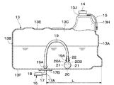
13は作動油タンク11の右側に隣接して旋回フレーム5上に搭載された燃料タンクである。この燃料タンク13は、キャブ6と左,右方向の反対側に位置して旋回フレーム5の前側に設けられている。また、燃料タンク13は、内部にエンジン7に供給する燃料を貯えるものであり、例えば樹脂材料を用いた成型加工により密閉容器として形成されている。即ち、燃料タンク13は、図5ないし図10に示すように、段差をもった前面部13A、後面部13B、左側面部13C、右側面部13D、上面部13Eおよび底面となる底面部13Fにより前,後方向に延びる異形な直方体状の容器として構成されている。
A
ここで、燃料タンク13は、旋回フレーム5の右前側の外側寄りに配設され、その外側面となる右側面部13Dは、旋回フレーム5を構成する右サイドフレーム5Dの前側側面5Eの円弧に沿うように、緩やかな円弧状側面となって湾曲している。また、燃料タンク13の右側面部13Dには、前,後方向の中間部に位置して燃料タンク13を旋回フレーム5に固定するための凹陥部13Gが形成されている。このため、燃料タンク13の底面部13Fは、左,右方向の寸法よりも前,後方向の寸法が大きな細長い略長方形状に形成されると共に、右側の一辺が略円弧状に形成されている。
Here, the
そして、燃料タンク13は、その後側が作動油タンク11のバッテリ搭載台11Aの下側に収まるように低く形成され、前側が上側に突出した突出部13Hとなっている。また、突出部13Hには、キャップ14によって開閉される給油口13Jが設けられている。さらに、燃料タンク13の前側上部にはレベルセンサ15が設けられ、該レベルセンサ15は、給油時に満タンに近いことを知らせるための透明なチューブによって形成されている。
And the
16は燃料タンク13に接続された燃料供給配管である。この燃料供給配管16は、燃料タンク13の底面部13Fに取り付けられたコネクタ17と、該コネクタ17に接続された燃料ホース18とによって構成されている。ここで、コネクタ17は、樹脂材料、金属材料等を用いて形成されたL字状の管路部17Aと、該管路部17Aの途中位置に設けられた鍔状のフランジ部17Bとを備え、フランジ部17Bが底面部13Fに取り付けられている。そして、管路部17Aは、例えば底面部13Fの中央部分に配置され、直線状に延びる一端側が燃料タンク13内に挿入されると共に、L字状に屈曲した他端側が燃料タンク13の外側に突出して燃料ホース18に接続されている。また、燃料ホース18には、燃料フィルタ、燃料ポンプ(いずれも図示せず)が取り付けられている。そして、燃料供給配管16は、燃料ポンプを用いて燃料タンク13内の燃料をエンジン7に向けて送り出すものである。
19は燃料タンク13内に位置してコネクタ17の管路部17Aに接続された可撓性ホースである。この可撓性ホース19は、基端側が燃料タンク13内で上側に向けて突出した管路部17Aに取り付けられると共に、先端側が後述の球体部材20に接続されている。ここで、可撓性ホース19は、例えば樹脂製のチューブを用いて弾性的に変形可能に形成されると共に、後述の球体部材20に比べて比重が小さい材料を用いて形成されている。そして、可撓性ホース19の両端側には、コネクタ17の管路部17Aと球体部材20の接続口22に対して抜止めするための固定バンド19Aがそれぞれ取り付けられている。
また、可撓性ホース19は、基端側が管路部17Aに沿って上側に向けて延びると共に、長さ方向の中間部分が逆U字状に湾曲している。これにより、可撓性ホース19の先端側は、中間部分から下側に向けて延び、燃料タンク13の底面部13Fの近傍に配置されている。そして、可撓性ホース19は、底面部13Fのうち管路部17Aから最も離れた部分と管路部17Aとの間の距離寸法Lよりも長い長さ寸法を有している。本実施の形態では、図7に示すように、可撓性ホース19の長さ寸法は、例えば管路部17Aと前面部13Aとの間の距離寸法Lよりも長く設定されている。これにより、可撓性ホース19は、球体部材20が底面部13Fのすべての位置に移動するのを許容している。
Further, the
20は可撓性ホース19の先端側に取り付けられた錘部材としての球体部材である。この球体部材20は、燃料よりも比重の大きい金属材料、樹脂材料等を用いて略球形状に形成されている。このため、球体部材20は、燃料タンク13の底面部13Fに当接した状態で燃料中に沈降する。また、球体部材20には、図7ないし図12に示すように、外表面20Aに開口した例えば2個の吸込口21が形成されている。ここで、2個の吸込口21は、例えば球体部材20の中心O1を挟んで径方向の両側にそれぞれ配置されている。
一方、球体部材20には、その外表面20Aよりも径方向の外側に向けて突出した円筒状の接続口22が設けられている。この接続口22は、例えば2個の吸込口21の中間位置に配置され、球体部材20内に穿設されたT字状の連通路20Bを通じて各吸込口21に連通している。そして、接続口22には、可撓性ホース19が取り付けられる。これにより、吸込口21は、可撓性ホース19を介して燃料供給配管16に接続されている。
On the other hand, the
また、接続口22の外周側には、円環状の鍔部22Aが形成されている。このとき、可撓性ホース19の先端側には、接続口22と一緒に鍔部22Aが挿入されている。一方、可撓性ホース19の外周側には、鍔部22Aよりも接続口22の基端側に位置して、可撓性ホース19の抜止めを行う固定バンド19Aが巻回されている。
An
本実施の形態による油圧ショベル1は上述の如き構成を有するもので、次に、その動作について説明する。
The
まず、オペレータは、キャブ6に搭乗して走行用の操作レバーを操作することにより、下部走行体2によって油圧ショベル1を前進または後退させることができる。また、作業用の操作レバー(いずれも図示せず)を操作することにより、作業装置4を俯仰動させて土砂の掘削作業等を行うことができる。
First, the operator can move the
また、下部走行体2が前下がりの傾斜地に到達したときには、図9に示すように、燃料タンク13の前面部13Aが後面部13Bよりも低くなり、燃料タンク13の前側に燃料が片寄る。このとき、球体部材20は、その重みによって球体部材20を燃料が溜まった燃料タンク13の前側に移動する。一方、下部走行体2が後下りの傾斜地に到達したときには、図10に示すように、燃料タンク13の後面部13Bが前面部13Aよりも低くなり、燃料タンク13の後側に燃料が片寄る。このとき、球体部材20は、その重みによって球体部材20を燃料が溜まった燃料タンク13の後側に移動する。同様に、下部走行体2が左,右方向に傾斜したときでも、燃料の片寄りが生じる。このときでも、球体部材20は燃料が溜まった方向に移動する。
Further, when the
このため、燃料の残量が少なくなって、燃料の液面が燃料供給配管16の管路部17Aよりも低くなるときでも、燃料中に球体部材20を沈めることができるから、球体部材20の吸込口21から燃料を吸い込んで、燃料供給配管16に送り出すことができる。この結果、燃料タンク13が前後左右のいずれの方向に傾いたときでも、球体部材20を燃料タンク13の最も低い位置に移動させて、燃料を最後まで送り出すことができる。
For this reason, the
かくして、本実施の形態によれば、球体部材20と燃料供給配管16との間を逆U字状に湾曲した可撓性ホース19を用いて接続したから、球体部材20は可撓性ホース19が届く範囲内で燃料タンク13内を自由に移動することができる。そして、燃料タンク13が傾いたときには、燃料タンク13内の最も低い位置に球体部材20が移動するから、燃料タンク13の角隅側に燃料が片寄るときでも、この燃料中に球体部材20を沈めて吸込口21から燃料を吸込むことができる。
Thus, according to the present embodiment, since the
特に、本実施の形態による小型の油圧ショベル1では、旋回フレーム5の右前側部位が下部走行体2の車幅内に入るように、右サイドフレーム5Dの前側側面5Eを履帯2Dの幅内で円弧形状に形成している。このように、小型の油圧ショベル1では、上部旋回体3上の設置範囲が極めて狭く、かつ空間に制約がある。この場合、上部旋回体3には多くの機器、配管を配置しているから、燃料タンク13は右端に配置されている。これにより、燃料タンク13は、その右側面部13Dが右サイドフレーム5Dの前側側面5Eに沿って円弧状に形成されている。また、燃料タンク13は、左,右方向の寸法に比べて前,後方向の寸法が長い異形な直方体状の容器として構成されている。このため、燃料タンク13の底面部13Fは、略長方形状をなして回転非対称な形状に形成されている。この結果、燃料タンク13が前,後方向に傾斜したときには、燃料供給配管16の管路部17Aよりも低い位置に多くの燃料が溜まる傾向がある。
In particular, in the small
このとき、従来技術のように、管路部17Aに回転可能な吸込管を取り付けた場合には、吸込管の長さ寸法は、燃料タンク13のうち前,後方向の寸法よりも短い左,右方向の寸法によって制限される。このため、吸込管の先端は前面部13A、後面部13B付近に配置することができないから、燃料タンク13が前,後方向に傾斜したときには、燃料を最後まで送り出せないという問題がある。
At this time, when a rotatable suction pipe is attached to the
これに対し、本実施の形態では、球体部材20を可撓性ホース19に接続したから、燃料タンク13の底面部13Fが回転非対称な細長い長方形状をなしているときでも、燃料タンク13の最も低い位置に球体部材20を移動させることができる。この結果、燃料タンク13が回転対称性を持たない形状であっても、確実に球体部材20を燃料が溜まる位置に移動させることができ、球体部材20の吸込口21を通じてほぼ全ての燃料を吸込むことができる。
On the other hand, in the present embodiment, since the
また、外形が球形状をなす球体部材20を可撓性ホース19に接続したから、燃料タンク13内に凹凸部分がある場合でも、球体部材20はこの凹凸部分を容易に乗り越えることができ、任意形状の燃料タンク13内で球体部材20を最も低い位置に移動させることができる。さらに、球体部材20には吸込口21を複数箇所に開口して設けたから、例えば一方の吸込口21が燃料タンク13の前面部13A、後面部13B、左側面部13C、右側面部13Dや底面部13Fで塞がれるときでも、他方の吸込口21は開口した状態となる。このため、燃料タンク13の傾斜に応じて球体部材20が移動しても、球体部材20のいずれかの吸込口21から燃料を吸い込むことができる。
In addition, since the
次に、図13は本発明の第2の実施の形態を示している。本実施の形態の特徴は、球体部材の吸込口を、接続口とは反対側の半球面のいずれかの位置に開口する構成としたことにある。なお、第2の実施の形態では、前述した第1の実施の形態と同一の構成要素に同一の符号を付し、その説明を省略するものとする。 Next, FIG. 13 shows a second embodiment of the present invention. The feature of this embodiment is that the inlet of the spherical member is configured to open at any position on the hemispherical surface opposite to the connection port. In the second embodiment, the same components as those in the first embodiment are denoted by the same reference numerals, and the description thereof is omitted.
31は第2の実施の形態による錘部材としての球体部材である。この球体部材31は、第1の実施の形態による球体部材20とほぼ同様に、燃料よりも比重の大きい金属材料、樹脂材料等を用いて略球形状に形成され、可撓性ホース19の先端側に取り付けられている。また、球体部材31には、外表面31Aに開口した例えば2個の吸込口32が形成されると共に、外表面31Aよりも径方向の外側に向けて突出した円筒状の接続口33が設けられている。この接続口33は、球体部材31内に穿設されたY字状の連通路31Bを通じて各吸込口32に連通すると共に、可撓性ホース19に接続されている。また、接続口33の外周側には、円環状の鍔部33Aが形成されている。
ここで、吸込口32は、接続口33とは反対側の半球面S2のいずれかの位置に開口している。即ち、接続口33は球体部材31の外表面31Aうち半球面S1の中心位置に配置されている。これに対し、吸込口32は球体部材31の外表面31Aうち残余の半球面S2のいずれかの位置に開口している。そして、接続口33が可撓性ホース19によって上側に引っ張られるときには、吸込口32は球体部材31の中心O1よりも下側に配置される。このため、燃料の液面が球体部材31の近傍まで低下したときでも、吸込口32を液面よりも下側に配置して、吸込口32が液面から露出するのを防止することができる。
Here, the
かくして、このように構成された第2の実施の形態においても、前述した第1の実施の形態とほぼ同様の作用効果を得ることができる。特に、本実施の形態では、球体部材31には外表面31Aよりも径方向の外側に突出した接続口33を設け、該接続口33に可撓性ホース19を接続する構成としたから、球体部材31の接続口33は可撓性ホース19に引っ張られて上側に配置される。一方、吸込口32は球体部材31の外表面31Aのうち接続口33とは反対側の半球面のいずれかの位置に開口するから、球体部材31の接続口33が上側に位置するのに対して、吸込口32は中心O1よりも下側に配置される。このため、球体部材31の一部が燃料の液面よりも上側に位置するときでも、吸込口32を燃料中に配置することができ、吸込口32からのエアの吸込みを防止することができる。
Thus, also in the second embodiment configured as described above, it is possible to obtain substantially the same operational effects as those of the first embodiment described above. In particular, in the present embodiment, the
次に、図14は本発明の第3の実施の形態を示している。本実施の形態の特徴は、吸込口には燃料フィルタを取り付ける構成としたことにある。なお、第3の実施の形態では、前述した第1の実施の形態と同一の構成要素に同一の符号を付し、その説明を省略するものとする。 Next, FIG. 14 shows a third embodiment of the present invention. The feature of this embodiment is that a fuel filter is attached to the suction port. Note that in the third embodiment, the same components as those in the first embodiment described above are denoted by the same reference numerals, and description thereof is omitted.
41は第3の実施の形態による錘部材としての球体部材である。この球体部材41は、第1の実施の形態による球体部材20とほぼ同様に、燃料よりも比重の大きい金属材料、樹脂材料等を用いて略球形状に形成されている。また、球体部材41には、外表面41Aに開口した吸込口42が設けられると共に、径方向の外側に突出した接続口43が設けられている。そして、吸込口42と接続口43は、連通路41Bを用いて互いに連通している。さらに、接続口43には、抜止め用の鍔部43Aが形成されている。また、吸込口42には、燃料をろ過する燃料フィルタ44が設けられている。この燃料フィルタ44は、燃料中の塵等が可撓性ホース19内に進入するのを防止している。
かくして、このように構成された第3の実施の形態においても、前述した第1の実施の形態とほぼ同様の作用効果を得ることができる。特に、本実施の形態では、吸込口42には燃料フィルタ44を取り付けるから、燃料フィルタ44によって燃料をろ過することができ、燃料中の塵等が可撓性ホース19内に進入するのを防止し、可撓性ホース19の目詰まりや流路断面積の減少を防止することができる。これにより、球体部材41、可撓性ホース19を通じて、確実に燃料を送り出すことができる。
Thus, also in the third embodiment configured as described above, it is possible to obtain substantially the same operational effects as those of the first embodiment described above. In particular, in this embodiment, since the
なお、前記各実施の形態では、球体部材20,31,41は単一の材料を用いて形成する構成としたが、例えば図15に示す変形例による球体部材20′のように、径方向に対して中心O1を挟んで接続口22とは反対側に比重の大きい錘51を埋設する構成としてもよい。これにより、吸込口21を確実に接続口22よりも下側に配置することができる。
In each of the embodiments described above, the
また、前記各実施の形態では、錘部材は外形が球形状の球体部材20,31,41を用いて構成した。しかし、本発明はこれに限らず、例えば横断面の面積が上部側に比べて底部側の方が大きな卵形状や水滴形状に形成してもよく、楕円体形状に形成してもよい。
In each of the above embodiments, the weight member is configured using the
また、前記各実施の形態では、球体部材20,31,41には2個の吸込口21,32,42を設ける構成した。しかし、本発明はこれに限らず、3個以上の吸込口を設ける構成としてもよい。
In each of the above embodiments, the
さらに、前記各実施の形態では、建設機械としてクローラ式の下部走行体2を備えた油圧ショベル1を例に挙げて説明した。しかし、本発明はこれに限るものではなく、例えばホイール式の下部走行体を備えた油圧ショベルに適用してもよい。さらに、油圧ショベル以外にも、例えば油圧クレーン、ホイールローダ、トラクタ等の他の建設機械にも広く適用することができる。
Furthermore, in each said embodiment, the
1 油圧ショベル(建設機械)
2 下部走行体(車体)
3 上部旋回体(車体)
7 エンジン
13 燃料タンク
13A 前面部
13B 後面部
13C 左側面部
13D 右側面部
13E 上面部
13F 底面部(底面)
16 燃料供給配管
17 コネクタ
18 燃料ホース
19 可撓性ホース
20,31,41,20′ 球体部材
20A,31A,41A 外表面
21,32,42 吸込口
22,33,43 接続口
44 燃料フィルタ
1 Excavator (construction machine)
2 Lower traveling body (car body)
3 Upper swing body (car body)
7
16
Claims (4)
前記燃料供給配管は前記燃料タンクの底面に接続して設け、
前記燃料タンク内には基端側が前記燃料供給配管に接続された可撓性ホースを設け、該可撓性ホースの先端側には燃料タンクの底面に当接する状態で沈降する錘部材を設け、該錘部材には前記可撓性ホースを通じて前記燃料供給配管に連通する吸込口を設けてなる建設機械において、
前記可撓性ホースは、基端側が前記燃料供給配管に接続されて上側に向けて延び、長さ方向の中間部分が逆U字状に湾曲し、先端側が該中間部分から下側に向けて延びて前記錘部材に取付けられる構成とし、
前記錘部材は外形が球形状、卵形状、水滴形状または楕円体形状をなす球体部材からなり、
該球体部材には、前記吸込口を複数箇所に開口して設け、
前記球体部材には、その外表面よりも外側に突出して前記可撓性ホースに接続されると共に前記吸込口に連通する接続口を設ける構成としたことを特徴とする建設機械。 E Bei the vehicle body equipped with the engine, a fuel tank storing fuel to be supplied to the engine provided in the vehicle body, and a fuel supply pipe connected to the fuel tank,
The fuel supply pipe is connected to the bottom surface of the fuel tank;
A flexible hose whose proximal end is connected to the fuel supply pipe is provided in the fuel tank, and a weight member that sinks while being in contact with the bottom surface of the fuel tank is provided at the distal end of the flexible hose. In the construction machine in which the weight member is provided with a suction port communicating with the fuel supply pipe through the flexible hose ,
The flexible hose has a proximal end connected to the fuel supply pipe and extending upward, an intermediate portion in the longitudinal direction curved in an inverted U shape, and a distal end side directed downward from the intermediate portion. It is configured to extend and attach to the weight member,
The weight member is composed of a spherical member whose outer shape is a spherical shape, an egg shape, a water droplet shape or an ellipsoid shape,
The spherical member is provided with the suction port opened at a plurality of locations,
A construction machine characterized in that the spherical member is provided with a connection port that protrudes outward from an outer surface thereof and is connected to the flexible hose and communicates with the suction port .
前記上部旋回体の前側には、土砂の掘削作業を行う作業装置が俯仰動可能に設けられ、
前記上部旋回体は、支持構造体を構成する旋回フレームと、該旋回フレームの左前側に設けられオペレータが搭乗するキャブと、前記旋回フレームの後側に横置き状態で搭載され油圧ポンプを駆動する前記エンジンと、前記旋回フレームの後部に取付けられ前記作業装置との重量バランスをとるカウンタウエイトと、前記キャブの右側に位置して前記旋回フレーム上に設けられた作動油タンクおよび前記燃料タンクと、前記エンジン、前記作動油タンクおよび前記燃料タンクを覆うように前記旋回フレーム上に設けられた建屋カバーとを備え、
前記燃料タンクは、前記旋回フレームの右側の外側寄りに配設されると共に、その底面は左,右方向の寸法よりも前,後方向の寸法が大きな細長い形状に形成され、
前記燃料供給配管は、前記燃料タンクの底面に取付けられたコネクタと、該コネクタに接続され前記エンジンに燃料を供給するための燃料ホースとによって構成され、
前記コネクタは、前記燃料タンクの底面の中央部分に配置され、
前記コネクタには、前記燃料タンク内で前記可撓性ホースが接続される構成としてなる請求項1,2または3に記載の建設機械。 The vehicle body includes a crawler-type lower traveling body and an upper revolving body that is provided on the lower traveling body so as to be able to swivel and is formed in a substantially circular shape when viewed from above so as not to collide with surrounding obstacles. And formed by
On the front side of the upper swing body, a working device for excavating earth and sand is provided so as to be able to move up and down,
The upper swing body is mounted in a swing frame that constitutes a support structure, a cab that is provided on the left front side of the swing frame and on which an operator rides, and is mounted horizontally on the rear side of the swing frame to drive a hydraulic pump. A counterweight attached to the rear portion of the engine and the swivel frame to balance the weight of the working device; a hydraulic oil tank and the fuel tank provided on the swivel frame on the right side of the cab; A building cover provided on the revolving frame so as to cover the engine, the hydraulic oil tank, and the fuel tank;
The fuel tank is disposed on the outer side on the right side of the swivel frame, and the bottom surface thereof is formed in an elongated shape having dimensions larger in the front and rear directions than in the left and right directions,
The fuel supply pipe is constituted by a connector attached to the bottom surface of the fuel tank, and a fuel hose connected to the connector and supplying fuel to the engine,
The connector is disposed at a central portion of the bottom surface of the fuel tank;
It said connector construction machine according to claim 1, 2 or 3 comprising a structure in which the flexible hose in the fuel tank is connected.
Priority Applications (3)
| Application Number | Priority Date | Filing Date | Title |
|---|---|---|---|
| JP2009198122A JP5069277B2 (en) | 2009-08-28 | 2009-08-28 | Construction machinery |
| KR1020100080682A KR101636420B1 (en) | 2009-08-28 | 2010-08-20 | Construction machine |
| CN201010266223.4A CN102001281B (en) | 2009-08-28 | 2010-08-27 | Engine machine |
Applications Claiming Priority (1)
| Application Number | Priority Date | Filing Date | Title |
|---|---|---|---|
| JP2009198122A JP5069277B2 (en) | 2009-08-28 | 2009-08-28 | Construction machinery |
Publications (3)
| Publication Number | Publication Date |
|---|---|
| JP2011047232A JP2011047232A (en) | 2011-03-10 |
| JP2011047232A5 JP2011047232A5 (en) | 2011-10-06 |
| JP5069277B2 true JP5069277B2 (en) | 2012-11-07 |
Family
ID=43809087
Family Applications (1)
| Application Number | Title | Priority Date | Filing Date |
|---|---|---|---|
| JP2009198122A Expired - Fee Related JP5069277B2 (en) | 2009-08-28 | 2009-08-28 | Construction machinery |
Country Status (3)
| Country | Link |
|---|---|
| JP (1) | JP5069277B2 (en) |
| KR (1) | KR101636420B1 (en) |
| CN (1) | CN102001281B (en) |
Families Citing this family (5)
| Publication number | Priority date | Publication date | Assignee | Title |
|---|---|---|---|---|
| KR101734973B1 (en) | 2011-05-30 | 2017-05-12 | 볼보 컨스트럭션 이큅먼트 에이비 | Fuel tank for heavy construction equipment |
| DE102014019425A1 (en) * | 2014-12-20 | 2016-06-23 | Man Diesel & Turbo Se | suction arrangement |
| CN107738573A (en) * | 2017-09-29 | 2018-02-27 | 无锡昊瑜节能环保设备有限公司 | A kind of fuel tank of vehicle |
| KR102369515B1 (en) * | 2021-10-14 | 2022-03-04 | 주식회사 한성엠에스 | High Efficiency Electro-Hydraulic Power Pack |
| US11852111B1 (en) * | 2022-08-31 | 2023-12-26 | Ford Global Technologies, Llc | Apparatus preventing fuel starvation on inclined surfaces |
Family Cites Families (11)
| Publication number | Priority date | Publication date | Assignee | Title |
|---|---|---|---|---|
| JPS4734403Y1 (en) * | 1970-06-26 | 1972-10-18 | ||
| JPS5629214Y2 (en) * | 1975-03-25 | 1981-07-11 | ||
| JPS6046411B2 (en) * | 1979-08-15 | 1985-10-16 | 三菱電機株式会社 | Manufacturing method of liquid crystal display element |
| JPS6113102Y2 (en) * | 1980-06-18 | 1986-04-23 | ||
| JPS5785789A (en) * | 1980-11-14 | 1982-05-28 | Ishikawajima Harima Heavy Ind | Shock absorber in lead-in device for crane |
| JPS60124725U (en) * | 1984-01-28 | 1985-08-22 | 三菱自動車工業株式会社 | Fuel tank fuel suction device |
| JP3579297B2 (en) * | 1999-06-10 | 2004-10-20 | 日立建機株式会社 | Swiveling construction machine |
| CN1248540A (en) * | 1999-08-18 | 2000-03-29 | 韩洪伟 | Flying-hammer fuel-tank capable of feeding fuel for long time under any flying condition for aeronautics and astronautics flyer |
| JP2002266377A (en) * | 2001-03-09 | 2002-09-18 | Komatsu Ltd | Fuel supply equipment for construction machinery |
| KR100974274B1 (en) * | 2007-11-28 | 2010-08-06 | 볼보 컨스트럭션 이키프먼트 홀딩 스웨덴 에이비 | excavator of mounting tank of having side door |
| JP4950080B2 (en) * | 2008-01-08 | 2012-06-13 | 日立建機株式会社 | Construction machinery |
-
2009
- 2009-08-28 JP JP2009198122A patent/JP5069277B2/en not_active Expired - Fee Related
-
2010
- 2010-08-20 KR KR1020100080682A patent/KR101636420B1/en active IP Right Grant
- 2010-08-27 CN CN201010266223.4A patent/CN102001281B/en not_active Expired - Fee Related
Also Published As
| Publication number | Publication date |
|---|---|
| CN102001281B (en) | 2015-02-25 |
| KR101636420B1 (en) | 2016-07-05 |
| CN102001281A (en) | 2011-04-06 |
| KR20110023766A (en) | 2011-03-08 |
| JP2011047232A (en) | 2011-03-10 |
Similar Documents
| Publication | Publication Date | Title |
|---|---|---|
| JP5069277B2 (en) | Construction machinery | |
| JP5054841B2 (en) | Wheeled work vehicle | |
| US10703195B2 (en) | Working machine | |
| EP2848741B1 (en) | Air cleaner for the engine of a wheel loader | |
| US8876163B2 (en) | Oil storage tank and construction vehicle | |
| JP6588239B2 (en) | Construction machinery | |
| US20160069043A1 (en) | Wheel loader | |
| JP3829071B2 (en) | Construction machinery | |
| JP4800983B2 (en) | Construction machinery | |
| JP2000144811A (en) | Turning type construction machine | |
| JP2011047232A5 (en) | ||
| JP6509767B2 (en) | Construction machinery | |
| JP2020133555A (en) | Construction machine | |
| CN102864803A (en) | Engineering machinery | |
| JP2016188557A (en) | Working machine | |
| JP5398641B2 (en) | Hydraulic oil tank and construction vehicle | |
| JP3207048U (en) | Concrete pump truck | |
| JP4539915B2 (en) | Hydraulic oil tank structure | |
| JP2023146848A (en) | Fuel tank of work vehicle | |
| JP4642633B2 (en) | Drug tank for drug spreader | |
| JP6859846B2 (en) | Construction machinery | |
| JP2009030346A (en) | Oil storage tank | |
| JP6121632B1 (en) | Work vehicle | |
| JPH1136363A (en) | Hydraulic oil tank for construction machine | |
| JPH11131527A (en) | Installed structure of tanks of construction machinery |
Legal Events
| Date | Code | Title | Description |
|---|---|---|---|
| A521 | Written amendment |
Free format text: JAPANESE INTERMEDIATE CODE: A523 Effective date: 20110818 |
|
| A621 | Written request for application examination |
Free format text: JAPANESE INTERMEDIATE CODE: A621 Effective date: 20110818 |
|
| A977 | Report on retrieval |
Free format text: JAPANESE INTERMEDIATE CODE: A971007 Effective date: 20111205 |
|
| A131 | Notification of reasons for refusal |
Free format text: JAPANESE INTERMEDIATE CODE: A131 Effective date: 20111213 |
|
| A521 | Written amendment |
Free format text: JAPANESE INTERMEDIATE CODE: A523 Effective date: 20120208 |
|
| TRDD | Decision of grant or rejection written | ||
| A01 | Written decision to grant a patent or to grant a registration (utility model) |
Free format text: JAPANESE INTERMEDIATE CODE: A01 Effective date: 20120814 |
|
| A01 | Written decision to grant a patent or to grant a registration (utility model) |
Free format text: JAPANESE INTERMEDIATE CODE: A01 |
|
| A61 | First payment of annual fees (during grant procedure) |
Free format text: JAPANESE INTERMEDIATE CODE: A61 Effective date: 20120816 |
|
| FPAY | Renewal fee payment (event date is renewal date of database) |
Free format text: PAYMENT UNTIL: 20150824 Year of fee payment: 3 |
|
| R150 | Certificate of patent or registration of utility model |
Ref document number: 5069277 Country of ref document: JP Free format text: JAPANESE INTERMEDIATE CODE: R150 Free format text: JAPANESE INTERMEDIATE CODE: R150 |
|
| S111 | Request for change of ownership or part of ownership |
Free format text: JAPANESE INTERMEDIATE CODE: R313113 |
|
| S531 | Written request for registration of change of domicile |
Free format text: JAPANESE INTERMEDIATE CODE: R313531 |
|
| R350 | Written notification of registration of transfer |
Free format text: JAPANESE INTERMEDIATE CODE: R350 |
|
| LAPS | Cancellation because of no payment of annual fees |