EP2714522B1 - Vorratsbündel - Google Patents
Vorratsbündel Download PDFInfo
- Publication number
- EP2714522B1 EP2714522B1 EP12719729.1A EP12719729A EP2714522B1 EP 2714522 B1 EP2714522 B1 EP 2714522B1 EP 12719729 A EP12719729 A EP 12719729A EP 2714522 B1 EP2714522 B1 EP 2714522B1
- Authority
- EP
- European Patent Office
- Prior art keywords
- supply bundle
- annular
- central axis
- bundle according
- supply
- Prior art date
- Legal status (The legal status is an assumption and is not a legal conclusion. Google has not performed a legal analysis and makes no representation as to the accuracy of the status listed.)
- Active
Links
Images



Classifications
-
- B—PERFORMING OPERATIONS; TRANSPORTING
- B68—SADDLERY; UPHOLSTERY
- B68G—METHODS, EQUIPMENT, OR MACHINES FOR USE IN UPHOLSTERING; UPHOLSTERY NOT OTHERWISE PROVIDED FOR
- B68G7/00—Making upholstery
- B68G7/05—Covering or enveloping cores of pads
- B68G7/051—Mattress-filling devices, i.e. sliding a tick or preformed cover over a cushion or sliding a cushion into a tick or preformed cover, e.g. by means of a press or of a depression table
Definitions
- the invention relates to a use of a supply bundle of a quantity of tubular, knitted circular, elastic tricot material, the supply bundle has a central axis, around the central axis around the amount is arranged annularly, the use of such a supply bundle is from the EP 136 766 B1 known.
- EP 136 766 B1 For example, there is known a device for holding a supply bundle of tricot material in a machine for obtaining a cuboid object. This applies in particular to the arrangement described there and specified in claim 1.
- the supply bundle consists of a quantity of tubular, round-knit, elastic tricot material. This amount is more or less irregularly compressed in the axial direction and combined in an annular amount.
- the hose or stocking of tricot material produced virtually endlessly in a circular knitting machine is pushed onto a pipe section and combined in the axial direction of the pipe section. It creates an irregular supply bundle.
- This is ring-shaped.
- the supply bundle 23 can be seen, which is summarized by four annular circumferential bands that carry the reference oak 26.
- the supply bundle bears the reference numeral 4.
- the tricot material can be deducted in the direction of a central axis, as for example, in the mentioned US 5,778,642 for the local material is shown.
- the irregularly combined supply in the annular amount is used up step by step.
- a disadvantage of the prior art device according to the EP 136 766 B1 it is that the force required to pull off the tricot material from the supply bundle is not constant. Depending on the random packing of the supply bundle, a larger or smaller force is required. The force to pull off also varies with the distance that is free between the respective end of the supply bundle and the front in the pulling direction withdrawal edges. In a fresh supply bundle, the way to the trigger edges is small, with a nearly spent supply bundle, the way is great. Accordingly, the friction varies. The jersey material must initially be pulled over a shorter distance, but then over an increasingly longer distance.
- tubular amount of tubular film made of plastic which is applied to a carrier body.
- the material of the tubular film is not described as elastic, it is not circular knit.
- the supply bundle has a central axis, which is formed by the carrier, around the central axis, the amount is arranged annularly.
- the tubular film has no fibers, it is not made of tricot material.
- the tubular film is folded in a zigzag shape in a plurality of superimposed layers, the individual layers being at an increasingly greater distance from the center axis. For use in a device for obtaining a cuboid article with tricot material, this tubular amount is unsuitable and not intended.
- the object of the invention is to avoid the disadvantages of using the known supply bundle and the use thereof of the prior art supply bundle to the effect that the stocking on the machine with constant force can be deducted from the supply bundle, that the supply bundle has a more regular structure, and that the supply bundle can be packaged even better with a larger number of supply bundles.
- this supply bundle can also be described such that a lowermost, first layer at least partially delimits the inner surface of the annular quantity.
- the next, the second layer is seen from the central axis outside this first position and runs, seen in the direction of the central axis, in the opposite direction to her.
- the third layer in turn runs in the same direction as the first layer, the third layer covers the second layer and has in the region of the second layer in contact with the first layer.
- the supply bundle can also be described so that no position of the central axis is closer than the first layer.
- the length of adjacent layers as viewed in the direction of the central axis is the same.
- an annular quantity is obtained whose cross-section is essentially rectangular in a radial plane.
- the respective layers hang together over bending lines or fold lines.
- the material is folded back by 180 °. This creates the zig-zag shape.
- the bending lines are preferably on radial planes to the central axis.
- all the bending lines of the first and second, the third and fourth, the fifth and sixth position, etc. so all bending lines, in which the lower layer is an odd number, substantially on a first common radial plane.
- it is preferable that they are on a second common one Radial level lie.
- the first radial plane and the second radial plane limit the dimension of the annular set in the direction of the central axis.
- the tricot material can be pulled off with the much more constant pull-off force.
- the distance between an end region of the supply bundle, e.g. the second common radial plane, and the discharge ends of the machine remains constant from the deduction of the nth, uppermost position to the deduction of the lowest, first position. A different friction does not occur.
- the tricot material according to the invention is regularly applied and folded, it can thereby deduct low. There is no problem with stagnation or congestion when pulling the jersey material. In the prior art, such a regular training is not available.
- the finished supply bundle is preferably present as a more or less cuboid object. Its length corresponds to half the outer circumference annular amount. The width corresponds to the length of a layer measured in the direction of the central axis. The thickness corresponds to twice the thickness of the cross section, ie twice the sum of the thickness of the n stacked layers. This item packs well. He is free of random cavities. Turbulence or irregularities do not occur.
- the tricot material used for the supply bundle is offered and distributed by the applicant. It is a tubular, circular knit, elastic in two directions material. This means that it is stretchable both in the direction of the tube and in the circumferential direction of the tube.
- the material is also referred to as a stocking, it is similar to a stocking made of plastic, for example nylon stocking (registered trademark nylon).
- the fibers are made of polyamide, polyester or other plastic, they can also be made of a different material, preferably also cotton is used.
- the titer ie the fineness, is in the range from 50 to 200 dtex, in particular in the range from 75 to 110 dtex.
- the tricot material has a basis weight of 5 to 200 g / m 2 , in particular 10 to 120 g / m 2 , in particular 10 to 120 g / m 2 .
- Elongation in both directions from the knitted material removed from the machine is at least 20%, preferably at least 40%.
- the extensibility is achieved by the material of the fibers and / or by the type of knitting. Instead of a knitting operation, other processes, in particular weaving processes, which are suitable for creating a round stocking can also be used.
- FIG. 1 shows supply bundle is ready for transport. It has an annular amount 20 of tricot material. Such an amount is in FIG. 2 as opposed to FIG. 2 However, the crowd is in FIG. 1 pressed flat. In FIG. 2 it has an internal cavity.
- the supply bundle after FIG. 1 also has an outer cover 22, it is made of transparent plastic film. This may have a thickness of 10-50 micrometers, just to give an example. Other packaging films are possible.
- the transparent film has the advantage that the content, namely the annular amount 20, is protected against moisture and dirt and is also immediately recognizable.
- the enclosure 22 is encompassed by two bands 24 made of a narrow strip, the ends of the strip being preferably welded.
- Such tapes are used very often for packaging in the field of packages and the like, they are known from the prior art. Cords, thicker threads and the like can also be used.
- a central axis 26 is used. It will become more apparent from the following. In particular FIG. 2 it indicates the geometric center axis of the annular set 20. This is also off FIG. 5 seen.
- the storage bundle has an extension of 20 to 150 cm, preferably 40 to 80 cm and in particular about 60 cm in the direction of this central axis 26.
- the dimensions transverse thereto, in the direction of the largest dimension, is about one to three times as large as the dimension in the direction of the central axis 26.
- the largest dimension of the supply bundle according to FIG. 1 is essentially determined by the manufacturing machine used, in particular knitting machine.
- the tricot material produced by a knitting machine (not shown) is usually wound up on a reel, this has seen in the axial direction, the length of half the diameter of the knitting tube. This measure in turn is determinative of the largest dimension of the supply bundle according to FIG. 1 , This largest dimension is in the range of one to two times the said axial dimension.
- FIGS. 2 to 5 show schematic representations, the finished product itself, namely the supply bundle, is in FIG. 1 shown.
- the annular amount 20 according to FIG. 2 has a lowermost, first layer 28, it defines the inner surface of the body shown.
- An n-th layer 30 defines the outer surface.
- Between this first layer 28 and the n-th layer 03 are more layers, so starting from the first layer 28, a second layer 32, a third layer 34, a fourth layer 36, a fifth layer 38, etc.
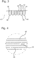
- the individual layers hang about fold lines 40 together. Looking at the front of the in FIG. 2 As shown in FIG.
- the body 20 representing the annular amount 20 is seen to have a plurality of fold lines 40 as shown in FIGS FIGS. 3 and 4 is apparent.
- the front surface of the body according to FIG. 2 is a first radial plane 42
- the rear surface parallel thereto is a second radial plane 44.
- the first radial plane 42 is formed by the fold lines 40 between each two layers, in which the lower layer is an odd number. It thus begins with the fold line 40 between the first layer 28 and the second layer 32, continues with the fold line between the third layer 34 and the fourth layer 36, etc.
- the second radial plane 44 is formed by the fold lines 40, in which, respectively a pair of forming layers as the lower layer have a straight-line position, so the fold line 40 of the second layer 32 in the third layer 34, the fold line 40 of the fourth layer 36 in the fifth layer 38, etc.
- the first radial plane 42 also still includes the end the nth layer 30.
- the second radial plane 44 includes the beginning of the first layer 28. Adjacent layers lie flat on each other and on top of each other.
- the arrangement of zig-zag superimposed layers thus described is a particularly regular training. It is possible a lower order.
- the fold lines 40 need not all lie in a respective radial plane. But preferred is the embodiment, as shown.
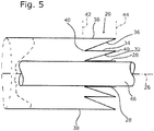
- FIG. 5 shows how a supplied from the left hose-shaped knitted stocking on a tube 46, which is only an aid here, is postponed.
- the beginning of the first layer 28 is placed on the tube 46.
- a fold line 40 between the first layer 28 and the second layer 32 defines the transition to the second layer 32, which is shown here obliquely to distinguish them clearly from the first layer 28 can. This also applies to the other layers.
- the second layer 32 is in the fold line 40 in turn in the third layer 34 via etc. to the fifth layer 38.
- the tube 46 can be removed later.
- the axis of the tube 46 also defines the central axis 26. It can be seen that the in FIG.
- the 5 shown structure is annular. It can also be seen the structure of the radial plane 42 and 44.
- the first radial plane 42 is located to the left of the fold and is defined by the local fold lines 40, while the second radial plane 44 is right, it is by the beginning of the first layer 28 and the two above Fold lines 40 defined.
- the intermediate piece 48 passes through the cavity of the annular set, as in FIG. 5 through the pipe 46 and in FIG. 2 is defined by the channel shown.
- the intermediate piece 48 is thus located between an upper run, a first part ring, for example the in FIG. 2 and FIG. 5 upper sub-ring, which extends over 180 °, and a lower run, a second, lower sub-ring, which extends over the remaining 180 °.
- the intermediate piece 48 avoids that the inner surface of the first layer 28 in the upper piece, also called the upper strand, comes into contact with the inner surface of the first layer 28 in the lower piece or lower strand of the annular set 20.
- the intermediate piece 48 makes it easier to find the internal cavity or channel that extends around the central axis 26. The order of the individual layers is better preserved.
- auxiliary threads, tapes or the like, as in FIG. 6 are indicated by the reference numeral 50, are pulled through the channel or cavity. They are preferably at the point where the arms of the device are later. This makes it easier for the user to bring the supply bundle to a device.
- the auxiliary threads 50 give an indication.
- the auxiliary threads 50 prevent the folded annular set 20, as shown in FIG. 1 is apparent, opens wrong.
- the same problem has also the intermediate piece 48th In the FIG. 1 is the annular amount 20 in the compressed state, the Figures 2 and 5 show an intermediate step in which the annular amount 20 is not yet in the compressed state.
- the sheath 22 and its intermediate piece 48 are each shown only schematically.
- the enclosure 22 encloses the annular set 20 relatively narrow.
- the wrapper is a closed bag that is essentially formed by two side walls. From the center of at least one side wall, the flat intermediate piece 48 projects. It is possible to connect the intermediate piece 48 with the at least one side wall or not.
- the intermediate piece 48 necessary part of the enclosure 22, which has the overall shape of a torus, often called donut, has.
Landscapes
- Engineering & Computer Science (AREA)
- Manufacturing & Machinery (AREA)
- Mechanical Engineering (AREA)
- Knitting Of Fabric (AREA)
- Packages (AREA)
- Auxiliary Devices For And Details Of Packaging Control (AREA)
Description
- Die Erfindung bezieht sich auf eine Verwendung eines Vorratsbündels einer Menge an schlauchförmigem, rundgestricktem, elastischem Trikotmaterial, das Vorratsbündel hat eine Mittelachse, um die Mittelachse herum ist die Menge ringförmig angeordnet, die Verwendung eines derartigen Vorratsbündels ist aus der
EP 136 766 B1
Aus derEP 136 766 B1 US 5,778,642 ist ein derartiges Vorratsbündel beispielsweise in denFiguren 1 und3 gezeigt, es trägt das Bezugszeichen 23. Man erkennt in Figur 3 die unregelmäßige axiale Stauchung. In derFigur 1 ist das Vorratsbündel 23 zu erkennen, das über vier ringförmig umlaufende Bänder, die das Bezugseichen 26 tragen, zusammengefasst ist. In derEP 136 766 B1
Wenn man ein Vorratsbündel an Trikotstoff, wie es in derEP 136 766 B1 US 5,778,642 für das dortige Material gezeigt ist. Dabei wird der unregelmäßig zusammengefasste Vorrat in der ringförmigen Menge Schritt für Schritt aufgebraucht. Zudem wird auf dieDE 10 2010 003 764 verwiesen. - Nachteilig bei der vorbekannten Vorrichtung nach der
EP 136 766 B1 - Schließlich ist die unregelmäßige Zusammenfassung der ringförmigen Menge zu einem Vorratsbündel nach dem Stand der Technik mit dem Nachteil behaftet, dass die Vorratsbündel sich unterschiedlich abziehen lassen und geometrisch unterschiedlich ausfallen. Die Form des fertigen Vorratsbündels ändert sich von Mal zu Mal. Ein optisch ansprechendes Aussehen wird nicht erreicht.
- Aus der
US 4,106,398 A ist eine schlauchförmige Menge an Schlauchfolie aus Kunststoff bekannt, die auf einen Trägerkörper aufgebracht ist. Das Material der Schlauchfolie wird nicht als elastisch beschrieben, es ist auch nicht rundgestrickt. Das Vorratsbündel hat eine Mittelachse, die vom Träger gebildet wird, um die Mittelachse herum ist die Menge ringförmig angeordnet. Die Schlauchfolie weist keine Fasern auf, sie ist nicht aus Trikotmaterial hergestellt. Die Schlauchfolie ist in mehreren, übereinanderliegenden Lagen zick-zack-förmig gefaltet, wobei die einzelnen Lagen sich in einem zunehmend größeren Abstand von der Mittelachse befinden. Für eine Verwendung in einer Vorrichtung zum Beziehen eines quaderförmigen Gegenstandes mit Trikotmaterial ist diese schlauchförmige Menge ungeeignet und nicht vorgesehen. - Aus der
US 4,265,439 A sind ein Verfahren und eine Vorrichtung bekannt, um ein Vorratsbündel aus der Schlauchfolie herzustellen. Für die Verwendung in einer Maschine zum Beziehen eines quaderförmigen Gegenstandes mit Trikotmaterial ist das so hergestellte Vorratsbündel nicht geeignet. - Hiervon ausgehend liegt nun der Erfindung die Aufgabe zugrunde, die Nachteile der Verwendung des vorbekannten Vorratsbündels zu vermeiden und die Verwendung des vorbekannten Vorratsbündels dahingehend weiterzuentwickeln, dass sich der Trikotstrumpf auf der Maschine mit konstanterer Kraft vom Vorratsbündel abziehen lässt, dass das Vorratsbündel eine regelmäßigere Struktur aufweist, und dass das Vorratsbündel noch besser mit einer größeren Anzahl von Vorratsbündeln verpackt werden kann.
- Diese Aufgabe wird gelöst durch die Verwendung nach Anspruch 1.
- Dieses Vorratsbündel kann alternativ auch so beschrieben werden, dass eine unterste, erste Lage die Innenfläche der ringförmigen Menge zumindest teilweise begrenzt. Die nächste, die zweite Lage liegt gesehen von der Mittelachse außerhalb dieser ersten Lage und verläuft, in Richtung der Mittelachse gesehen, in Gegenrichtung zu ihr. Die dritte Lage wiederum verläuft in gleicher Richtung wie die erste Lage, die dritte Lage überdeckt die zweite Lage und hat im Bereich der zweiten Lage einen Kontakt mit der ersten Lage. In einer weiteren Alternative kann das Vorratsbündel auch so beschrieben werden, dass keine Lage der Mittelachse näher ist als die erste Lage.
- Im Gegensatz zu einer Faltung, wie sie beispielsweise in
Figur 3 der genanntenUS 5,778,642 angedeutet ist und der Ausbildung einer Zieharmonika bzw. eines Wellrohrs (siehe z.B.EP 182 001 EP 349 778 - Vorzugsweise ist die Länge benachbarter Lagen, gesehen in Richtung der Mittelachse, gleich. Dadurch wird eine ringförmige Menge erhalten, deren Querschnitt in einer Radialebene gesehen im Wesentlichen rechteckförmig ist.
- Die jeweiligen Lagen hängen über Biegelinien bzw. Faltlinien zusammen. In den Biegelinien ist das Material um 180° zurückgefaltet. Dadurch kommt die Zick-Zack-Form zustande. Die Biegelinien liegen vorzugsweise auf Radialebenen zur Mittelachse. Vorzugsweise liegen alle Biegelinien der ersten und zweiten, der dritten und vierten, der fünften und sechsten Lage usw., also alle Biegelinien, bei denen die untere Lage eine ungerade Zahl ist, im Wesentlichen auf einer ersten gemeinsamen Radialebene. Ebenso ist es für die Biegelinien, bei denen die untere Lage eine gerade Zahl ist, so, dass sie vorzugsweise auf einer zweiten gemeinsamen Radialebene liegen. Die erste Radialebene und die zweite Radialebene begrenzen die Abmessung der ringförmigen Menge in Richtung der Mittelachse.
- Bei diesem Vorratsbündel lässt sich das Trikotmaterial mit der wesentlich konstanteren Abzugskraft abziehen. Der Abstand zwischen einem Endbereich des Vorratsbündels, z.B. der zweiten gemeinsamen Radialebene, und den Abzugsenden der Maschine bleibt vom Abzug der n-ten, obersten Lage bis zum Abzug der untersten, ersten Lage konstant. Eine unterschiedliche Reibung tritt nicht auf. Das Trikotmaterial ist erfindungsgemäß regelmäßig aufgebracht und gefaltet, es lässt sich dadurch günstig abziehen. Es besteht kein Problem mit Stockungen oder Stauungen beim Abzug des Trikotmaterials. Im vorbekannten Stand der Technik liegt eine derartige regelmäßige Ausbildung nicht vor.
- Das fertige Vorratsbündel liegt vorzugsweise als mehr oder weniger quaderförmiger Gegenstand vor. Seine Länge entspricht dem halben Außenumfang ringförmigen Menge. Die Breite entspricht der in Richtung der Mittelachse gemessenen Länge einer Lage. Die Dicke entspricht der doppelten Dicke des Querschnitts, also der doppelten Summe der Dicke der n übereinander geschichteten Lagen. Dieser Gegenstand lässt sich gut verpacken. Er ist frei von zufälligen Hohlräumen. Verwirbelungen oder Unregelmäßigkeiten treten nicht auf.
- Weitere Vorzüge und Merkmale der Erfindung ergeben sich aus den übrigen Ansprüchen sowie der nun folgenden Beschreibung von nicht einschränkend zu verstehenden Ausführungsbeispielen der Erfindung. In dieser zeigen:
- Fig. 1:
- eine perspektivische Darstellung eines fertigen, für den Handel geeigneten Vorratsbündels,
- Fig. 2:
- eine perspektivische Darstellung eines Zwischenschritts in der Herstellung des Vorratsbündels gemäß
Figur 1 , gezeigt ist eine ringförmige Menge an geordnet zusammengefasstem Trikotmaterial, - Fig. 3:
- ein Schnittbild entlang der Schnittlinie III-III in
Figur 2 , - Fig. 4:
- eine Ansicht auf das Detail IV in der angegebenen Blickrichtung in
Figur 2 , - Fig. 5:
- eine schematische Darstellung zur Erläuterung des Herstellvorgangs des Vorratsbündels, gezeigt ist ein Rohrstück, auf das zick-zack-förmig Lagen des Trikotmaterials aufgebracht werden, zur besseren Darstellung sind die Lagen voneinander separiert,
- Fig. 6:
- eine prinzipielle Darstellung in Form eines Schnitts in der radialen Schnittebene VI-VI für eine ringförmige Menge, die eine Umhüllung in einer ersten Ausbildung aufweist und
- Fig. 7:
- eine prinzipielle Darstellung in Form eines Schnitts in der radialen Schnittebene VI-VI für eine ringförmige Menge, die eine Umhüllung in einer zweiten Ausbildung aufweist.
- Das für das Vorratsbündel verwendete Trikotmaterial wird von der Anmelderin angeboten und vertrieben. Es handelt sich um schlauchförmiges, rundgestricktes, in zwei Richtungen elastisches Material. Dies bedeutet, dass es sowohl in Richtung des Schlauchs als auch in Umfangsrichtung des Schlauchs dehnbar ist. Das Material wird auch als Strumpf bezeichnet, es hat Ähnlichkeit mit einem aus Kunststoff gefertigten Strumpf, beispielsweise Nylonstrumpf (eingetragene Marke Nylon). Die Fasern sind aus Polyamid, Polyester oder einem anderen Kunststoff, sie können auch aus einem anderen Material sein, vorzugsweise wird auch Baumwolle eingesetzt. Der Titer, also die Feinheit, liegt im Bereich von 50 bis 200 dtex, insbesondere im Bereich von 75 bis 110 dtex. Das Trikotmaterial hat ein Flächengewicht von 5 bis 200 g/m2, insbesondere 10 bis 120 g/m2, insbesondere 10 bis 120 g/m2. Die Dehnung in beiden Richtungen ausgehend vom von der Maschine entnommenen, gestrickten Material beträgt mindestens 20%, vorzugsweise mindestens 40%. Die Dehnbarkeit ist durch das Material der Fasern und/oder durch die Art des Strickens erreicht. Anstelle eines Strickvorgangs können auch andere Vorgänge, insbesondere Webvorgänge eingesetzt werden, die für das Erstellen eines runden Strumpfs geeignet sind.
- Das in
Figur 1 gezeigte Vorratsbündel ist für den Transport fertig. Es weist eine ringförmige Menge 20 an Trikotmaterial auf. Eine derartige Menge ist inFigur 2 dargestellt, im Unterschied zuFigur 2 ist die Menge jedoch inFigur 1 flach zusammengedrückt. InFigur 2 weist sie einen inneren Hohlraum auf. Das Vorratsbündel nachFigur 1 weist weiterhin eine äußere Umhüllung 22 auf, sie ist aus transparenter Kunststofffolie hergestellt. Diese kann eine Dicke von 10-50 Mikrometer, um nur ein Beispiel zu geben, haben. Andere Verpackungsfolien sind möglich. Die transparente Folie hat den Vorteil, dass der Inhalt, nämlich die ringförmige Menge 20, gegen Feuchtigkeit und Verschmutzungen geschützt ist und darüber hinaus unmittelbar erkennbar ist. - Die Umhüllung 22 wird von zwei Bändern 24 umgriffen, die aus einem schmalen Streifen hergestellt sind, die Enden des Streifens sind vorzugsweise verschweißt. Derartige Bänder werden für die Verpackung im Bereich von Paketen und dergleichen sehr häufig eingesetzt, sie sind aus dem Stand der Technik bekannt. Verwendet werden können auch Schnüre, dickere Fäden und dergleichen.
- Für die Beschreibung des Vorratsbündels wird eine Mittelachse 26 verwendet. Sie wird aus dem Folgenden besser ersichtlich. Wie insbesondere
Figur 2 zeigt, bezeichnet sie die geometrische Mittelachse der ringförmigen Menge 20. Dies ist auch ausFigur 5 ersichtlich. - Das Vorratsbündel hat in Richtung dieser Mittelachse 26 eine Erstreckung von 20 bis 150 cm, vorzugsweise 40 bis 80 cm und insbesondere etwa 60 cm. Die Abmessungen quer hierzu, in der Richtung der größten Abmessung, ist etwa ein bis dreimal so groß wie die Abmessung in Richtung der Mittelachse 26. Die größte Abmessung des Vorratsbündels gemäß
Figur 1 wird im Wesentlichen durch die verwendete Herstellmaschine, insbesondere Strickmaschine, bestimmt. Das von einer Strickmaschine (nicht dargestellt) hergestellte Trikotmaterial wird üblicherweise auf eine Rolle aufgewickelt, diese hat in Axialrichtung gesehen die Länge des halben Durchmessers des Strickschlauchs. Dieses Maß wiederum ist bestimmend für die größte Abmessung des Vorratsbündels gemäßFigur 1 . Diese größte Abmessung liegt im Bereich des Ein- bis Zweifachen der genannten axialen Abmessung. - Anhand der
Figuren 2 bis 5 wird nun der Aufbau der ringförmigen Menge 20 erläutert. Diese Figuren zeigen schematische Darstellungen, das fertige Produkt selbst, nämlich das Vorratsbündel, ist inFigur 1 gezeigt. Die ringförmige Menge 20 gemäßFigur 2 hat eine unterste, erste Lage 28, sie definiert die Innenfläche des gezeigten Körpers. Eine n-te Lage 30 definiert die Außenfläche. Zwischen dieser ersten Lage 28 und der n-ten Lage 03 befinden sich weitere Lagen, also ausgehend von der ersten Lage 28 eine zweite Lage 32, eine dritte Lage 34, eine vierte Lage 36, eine fünfte Lage 38 usw.. Die einzelnen Lagen hängen über Faltlinien 40 zusammen. Schaut man auf die Frontseite des inFigur 2 dargestellten Körpers, der die ringförmige Menge 20 darstellt, so schaut man auf eine Vielzahl von Faltlinien 40, wie dies aus denFiguren 3 und 4 ersichtlich ist. Die Frontfläche des Körpers gemäßFigur 2 ist eine erste Radialebene 42, die hierzu parallele Rückfläche ist eine zweite Radialebene 44. Die erste Radialebene 42 wird durch die Faltlinien 40 zwischen jeweils zwei Lagen gebildet, bei denen die untere Lage eine ungerade Zahl ist. Es beginnt also mit der Faltlinie 40 zwischen der ersten Lage 28 und der zweiten Lage 32, geht weiter mit der Faltlinie zwischen der dritten Lage 34 und der vierten Lage 36 usw.. Die zweite Radialebene 44 wird durch die Faltlinien 40 gebildet, bei denen jeweils ein Paar bildenden Lagen als untere Lage eine geradzeilige Lage haben, also die Faltlinie 40 der zweiten Lage 32 in die dritte Lage 34, die Faltlinie 40 der vierten Lage 36 in die fünfte Lage 38 usw.. Die erste Radialebene 42 beinhaltet auch noch das Ende der n-ten Lage 30. Die zweite Radialebene 44 beinhaltet den Anfang der ersten Lage 28. Benachbarte Lagen liegen flächig aufeinander und übereinander. - Die so beschriebene Anordnung von zick-zack-förmig übereinanderliegenden Lagen ist eine besonders regelmäßige Ausbildung. Es ist eine geringere Ordnung möglich. Die Faltlinien 40 müssen nicht alle in einer jeweiligen Radialebene liegen. Bevorzugt ist aber die Ausführung, wie sie dargestellt ist.
-
Figur 5 zeigt, wie ein von links zugeführter schlauchförmiger Strickstrumpf auf ein Rohr 46, das hier nur ein Hilfsmittel darstellt, aufgeschoben wird. Der Anfang der ersten Lage 28 ist auf das Rohr 46 aufgelegt. Eine Faltlinie 40 zwischen der ersten Lage 28 und der zweiten Lage 32 definiert den Übergang zur zweiten Lage 32, die hier schräg dargestellt ist, um sie deutlich von der ersten Lage 28 unterscheiden zu können. Dies gilt auch für die weiteren Lagen. Die zweite Lage 32 geht in der Faltlinie 40 wiederum in die dritte Lage 34 über usw. bis zur fünften Lage 38. Um den Aufbau gemäßFigur 2 zu erhalten, müssen die einzelnen Lagen noch in Radialrichtung des Rohrs 46 zusammengedrückt werden. Das Rohr 46 kann später entfernt werden. Die Achse des Rohrs 46 definiert auch die Mittelachse 26. Man erkennt, dass die inFigur 5 gezeigte Struktur ringförmig vorliegt. Man erkennt auch den Aufbau der Radialebene 42 und 44. Die erste Radialebene 42 liegt links der Faltung und wird durch die dortigen Faltlinien 40 definiert, während die zweite Radialebene 44 rechts liegt, sie wird durch den Anfang der ersten Lage 28 und die beiden darüber liegenden Faltlinien 40 definiert. - In kinematischer Umkehr ist es auch möglich, von außen nach innen zu falten. Man beginnt dann mit der n-ten Lage und faltet bis zur ersten Lage.
- Um die ringförmige Menge 20 für den Vertrieb fertigzustellen, wird sie mit der beschriebenen Umhüllung 22 versehen. Diese weist in vorzugsweiser Ausbildung ein Zwischenstück 48 und/oder Hilfsfäden 50 auf. Das Zwischenstück 48 durchgreift den Hohlraum der ringförmigen Menge, wie er in
Figur 5 durch das Rohr 46 und inFigur 2 durch den gezeigten Kanal definiert ist. Das Zwischenstück 48 befindet sich somit zwischen einem Obertrum, einem ersten Teilring, z.B. dem inFigur 2 undFigur 5 oberen Teilring, der sich über 180° erstreckt, und einem Untertrum, einem zweiten, unteren Teilring, der sich über die restlichen 180° erstreckt. Anders ausgedrückt vermeidet das Zwischenstück 48, dass die Innenfläche der ersten Lage 28 im oberen Stück, auch Obertrum genannt, in Kontakt kommt mit der Innenfläche der ersten Lage 28 im unteren Stück bzw. Untertrum der ringförmigen Menge 20. Durch das Zwischenstück 48 wird es einfacher, den inneren Hohlraum bzw. Kanal, der sich um die Mittelachse 26 erstreckt, aufzufinden. Die Ordnung der einzelnen Lagen bleibt besser erhalten. Zusätzlich oder alternativ können auch Hilfsfäden, Bänder oder dergl., wie sie inFigur 6 mit dem Bezugszeichen 50 angedeutet sind, durch den Kanal bzw. Hohlraum hindurchgezogen werden. Sie befinden sich vorzugsweise an der Stelle, an der später die Arme der Vorrichtung sich befinden. Dadurch wird es dem Benutzer erleichtert, das Vorratsbündel auf eine Vorrichtung zu bringen. Die Hilfsfäden 50 geben einen Hinweis. Außerdem verhindern die Hilfsfäden 50, dass man die zusammengeklappte ringförmige Menge 20, wie sie inFigur 1 ersichtlich ist, falsch öffnet. Die gleiche Aufgabe hat auch das Zwischenstück 48. In derFigur 1 befindet sich die ringförmige Menge 20 im zusammengedrückten Zustand, dieFiguren 2 und5 zeigen einen Zwischenschritt, in dem sich die ringförmige Menge 20 noch nicht im zusammengedrückten Zustand befindet. - In
Figur 6 und 7 sind die Umhüllung 22 und ihr Zwischenstück 48 jeweils nur schematisch dargestellt. In beiden Fällen umschließt die Umhüllung 22 die ringförmige Menge 20 relativ eng. InFig. 5 ist die Umhüllung eine geschlossene Tasche, die im Wesentlichen durch zwei Seitenwände gebildet ist. Von der Mitte mindestens einer Seitenwand springt das flache Zwischenstück 48 vor. Es ist möglich, das Zwischenstück 48 mit der mindestens einen Seitenwand zu verbinden oder nicht. In der Ausführung nachFigur 6 ist das Zwischenstück 48 notwendiges Teil der Umhüllung 22, die insgesamt die Form eines Torus, oft auch Doughnut bezeichnet, hat.
Claims (10)
- Verwendung eines Vorratsbündel einer Menge an schlauchförmigem, rundgestricktem, elastischem Trikotmaterial, das Vorratsbündel hat eine Mittelachse (26), um die Mittelachse (26) herum ist die Menge ringförmig angeordnet, das Trikotmaterial weist Fasern mit einem Titer bzw. einer Feinheit von 30 bis 200 dtex auf, das Trikotmaterial ist in mehreren, übereinander liegenden Lagen zick-zack-förmig gefaltet, wobei die einzelnen Lagen sich in einem zunehmend größeren Abstand von der Mittelachse (26) befinden in einer Maschine zum Beziehen eines quaderförmigen Gegenstandes mit dem Trikotmaterial.
- Verwendung eines Vorratsbündels nach Anspruch 1, dadurch gekennzeichnet, dass die ringförmige Menge (20) ein Mittel zur Lagefixierung, insbesondere mindestens ein geschlossenes, um die ringförmige Menge (20) umlaufendes Band (24) aufweist.
- Verwendung eines Vorratsbündels nach einem der vorangegangenen Ansprüche, dadurch gekennzeichnet, dass das Vorratsbündel eine Umhüllung (22) aufweist, die die ringförmige Menge (20) umschließt.
- Verwendung eines Vorratsbündels nach Anspruch 1, dadurch gekennzeichnet, dass die Umhüllung (22) die Form eines Ringschlauchs hat oder dass die Umhüllung (22) ein Zwischenstück (48) aufweist, das parallel zur Mittelachse (26) durch die ringförmige Menge (20) hindurch reicht.
- Verwendung eines Vorratsbündels nach einem der vorangegangenen Ansprüche, dadurch gekennzeichnet, dass in Richtung der Mittelachse (26) gesehen die Länge der ringförmigen Menge 20 bis 100 cm, vorzugsweise 50 bis 70 cm, insbesondere 60 cm beträgt.
- Verwendung eines Vorratsbündels nach einem der vorangegangenen Ansprüche, dadurch gekennzeichnet, dass die ringförmige Menge (20) mindestens zwanzig Lagen, insbesondere fünfzig Lagen, vorzugsweise mindestens hundert Lagen aufweist.
- Verwendung eines Vorratsbündels nach einem der vorangegangenen Ansprüche, dadurch gekennzeichnet, dass in Richtung der Mittelachse (26) gesehen die Lagen eine Länge haben, die mit einer Abweichung von 10% für jede Lage gleich ist.
- Verwendung eines Vorratsbündels nach einem der vorangegangenen Ansprüche, dadurch gekennzeichnet, dass die Fasern einen Titer bzw. eine Feinheit von 50 bis 150 dtex aufweisen.
- Verwendung eines Vorratsbündels nach einem der vorangegangenen Ansprüche, dadurch gekennzeichnet, dass die ringförmige Menge (20) um zwei parallel zur Mittelachse (26) verlaufende Biegelinien zu einer flachen Einheit zusammengefaltet ist.
- Verwendung eines Vorratsbündels nach einem der vorangegangenen Ansprüche, dadurch gekennzeichnet, dass die ringförmige Menge (20) zwei Teilringe aufweist, und dass eine unterste Lage der beiden Teilringe miteinander in Kontakt ist, insbesondere im Bereich der Mittelachse (26) miteinander in Kontakt ist.
Priority Applications (3)
| Application Number | Priority Date | Filing Date | Title |
|---|---|---|---|
| HRP20180332TT HRP20180332T1 (hr) | 2011-05-23 | 2012-05-09 | Pričuvni svežanj |
| PL12719729T PL2714522T3 (pl) | 2011-05-23 | 2012-05-09 | Wiązka z zapasem |
| RS20180270A RS57017B1 (sr) | 2011-05-23 | 2012-05-09 | Snabdevajuća bala |
Applications Claiming Priority (2)
| Application Number | Priority Date | Filing Date | Title |
|---|---|---|---|
| DE102011102944 | 2011-05-23 | ||
| PCT/EP2012/058571 WO2012159885A1 (de) | 2011-05-23 | 2012-05-09 | Vorratsbündel |
Publications (2)
| Publication Number | Publication Date |
|---|---|
| EP2714522A1 EP2714522A1 (de) | 2014-04-09 |
| EP2714522B1 true EP2714522B1 (de) | 2017-12-20 |
Family
ID=46046223
Family Applications (1)
| Application Number | Title | Priority Date | Filing Date |
|---|---|---|---|
| EP12719729.1A Active EP2714522B1 (de) | 2011-05-23 | 2012-05-09 | Vorratsbündel |
Country Status (10)
| Country | Link |
|---|---|
| EP (1) | EP2714522B1 (de) |
| DE (1) | DE202012013140U1 (de) |
| DK (1) | DK2714522T3 (de) |
| ES (1) | ES2657922T3 (de) |
| HR (1) | HRP20180332T1 (de) |
| HU (1) | HUE036376T2 (de) |
| LT (1) | LT2714522T (de) |
| PL (1) | PL2714522T3 (de) |
| RS (1) | RS57017B1 (de) |
| WO (1) | WO2012159885A1 (de) |
Families Citing this family (1)
| Publication number | Priority date | Publication date | Assignee | Title |
|---|---|---|---|---|
| EP4589065A1 (de) | 2024-01-22 | 2025-07-23 | FillMatic Polsterindustriemaschinen GmbH | Bündelmaschine |
Citations (2)
| Publication number | Priority date | Publication date | Assignee | Title |
|---|---|---|---|---|
| EP0136766B1 (de) * | 1983-10-24 | 1986-05-28 | Chris Heijnen | Behälter zum Halten eines Vorratbündel von Trikotstrumpf, in einer Vorrichtung zum Beziehen eines tablettförmigen Gegenstandes im genannten Trikot |
| DE102010003764A1 (de) * | 2009-05-12 | 2011-03-17 | Chris Heynen Systems B.V. | Vorrichtung und Verfahren zum Umhüllen von Matratzen mit einem Trikotmaterial |
Family Cites Families (6)
| Publication number | Priority date | Publication date | Assignee | Title |
|---|---|---|---|---|
| US4134892A (en) * | 1976-03-17 | 1979-01-16 | Aktiebolaget Platmanufaktur | Packing material |
| FR2345282A2 (fr) * | 1976-03-23 | 1977-10-21 | Scrrb | Procede et dispositif pour le pliage transversal d'une gaine tubulaire |
| DE3441565A1 (de) | 1984-11-14 | 1986-05-15 | Fritz Hahn Kg, 5500 Trier | Verfahren und vorrichtung zum herstellen eines flexiblen wellrohres sowie nach dem verfahren hergestelltes flexibles wellrohr |
| CA1303638C (en) * | 1987-01-29 | 1992-06-16 | Dwight Smith-Gander | Method and apparatus for folding an elongate storage bag |
| JP2767427B2 (ja) | 1988-07-05 | 1998-06-18 | 三菱樹脂株式会社 | コルゲート管の製造方法 |
| US5778642A (en) | 1996-06-28 | 1998-07-14 | Free-Flow Packaging International, Inc. | System and method for use of loose fill packing materials |
-
2012
- 2012-05-09 DK DK12719729.1T patent/DK2714522T3/en active
- 2012-05-09 RS RS20180270A patent/RS57017B1/sr unknown
- 2012-05-09 HU HUE12719729A patent/HUE036376T2/hu unknown
- 2012-05-09 PL PL12719729T patent/PL2714522T3/pl unknown
- 2012-05-09 DE DE201220013140 patent/DE202012013140U1/de not_active Expired - Lifetime
- 2012-05-09 WO PCT/EP2012/058571 patent/WO2012159885A1/de not_active Ceased
- 2012-05-09 EP EP12719729.1A patent/EP2714522B1/de active Active
- 2012-05-09 HR HRP20180332TT patent/HRP20180332T1/hr unknown
- 2012-05-09 ES ES12719729.1T patent/ES2657922T3/es active Active
- 2012-05-09 LT LTEP12719729.1T patent/LT2714522T/lt unknown
Patent Citations (2)
| Publication number | Priority date | Publication date | Assignee | Title |
|---|---|---|---|---|
| EP0136766B1 (de) * | 1983-10-24 | 1986-05-28 | Chris Heijnen | Behälter zum Halten eines Vorratbündel von Trikotstrumpf, in einer Vorrichtung zum Beziehen eines tablettförmigen Gegenstandes im genannten Trikot |
| DE102010003764A1 (de) * | 2009-05-12 | 2011-03-17 | Chris Heynen Systems B.V. | Vorrichtung und Verfahren zum Umhüllen von Matratzen mit einem Trikotmaterial |
Also Published As
| Publication number | Publication date |
|---|---|
| DK2714522T3 (en) | 2018-03-05 |
| DE202012013140U1 (de) | 2014-12-11 |
| ES2657922T3 (es) | 2018-03-07 |
| RS57017B1 (sr) | 2018-05-31 |
| WO2012159885A1 (de) | 2012-11-29 |
| EP2714522A1 (de) | 2014-04-09 |
| HUE036376T2 (hu) | 2018-07-30 |
| PL2714522T3 (pl) | 2018-06-29 |
| HRP20180332T1 (hr) | 2018-06-01 |
| LT2714522T (lt) | 2018-03-26 |
Similar Documents
| Publication | Publication Date | Title |
|---|---|---|
| DE1735017B2 (de) | Einteilige Wickelhülse aus Kunststoff, insbesondere zur Aufnahme von Garnwicklungen | |
| DE3703547A1 (de) | Verfahren zum herstellen einer rundschlinge | |
| WO2012098122A1 (de) | Verfahren zum herstellen einer schlauchförmigen faseranordnung eines faserverstärkten verbundbauteils und schlauchförmige faseranordnung | |
| EP3666680B1 (de) | Glaskörperlage, glaskörperbündel sowie packverfahren | |
| DE4320303C1 (de) | Mehrfachbreiter Faserstreifen sowie ein Verfahren und eine Vorrichtung zu dessen Herstellung | |
| DE102007029310A1 (de) | Wendelverteiler für eine Blasfolienanlage | |
| DE2424665C3 (de) | Druckschlauch mit Verstärkungseinlagen | |
| DE2546278B1 (de) | Schlauchnetz zum umhuellen von wuersten und fleischwaren | |
| DE202012013140U1 (de) | Vorratsbündel | |
| DE3228033A1 (de) | Spirale grosser laenge zur herstellung eines spiralbandes und verfahren und vorrichtung zum einbringen von fuellmaterial in diese spiralen | |
| DE102016107553B3 (de) | Verfahren zur Herstellung eines endlosen Treibriemens | |
| DE3206636A1 (de) | Vorrichtung zum herstellen von metallschnueren | |
| AT15514U1 (de) | Kletterseil und Verfahren zur Herstellung | |
| EP2962028B1 (de) | Strickschrumpfschlauch und verfahren zu dessen herstellung | |
| DE2128838A1 (de) | Vorrichtung und Verfahren zum Kräuseln von Fadenmaterial | |
| DE606311C (de) | Gummischlauch mit eingelegten Fadenschichten | |
| DE102016008111A1 (de) | Verfahren zur Herstellung eines Schlauchanschlusses und Schlauchanschluss | |
| DE3124690C2 (de) | Verfahren und Vorrichtung zur Bündelbildung vorgefertigter Umreifungsdrähte | |
| DE3303674A1 (de) | Verarbeitung von werg, hauptsaechlich fuer die filterstrangfertigung | |
| WO2012140046A1 (de) | Verfahren zur herstellung eines moduls, insbesondere endlosmoduls, für eine papiermaschinenbespannung und endlosmodul | |
| DE2546278C3 (de) | ||
| DE102012112335B4 (de) | Kompressionsverpackung, Verpackungseinheit sowie Verfahren zur Herstellung einer Verpackungseinheit | |
| DE2940054C2 (de) | Drahtgeflechtbahn aus Viereckgeflecht und Verfahren zu deren Herstellung | |
| AT150846B (de) | Zusammengesetzter elastischer Faden. | |
| DE102013103368A1 (de) | Formeinheit einer Vorrichtung zum Schlingen von Brezeln |
Legal Events
| Date | Code | Title | Description |
|---|---|---|---|
| REG | Reference to a national code |
Ref country code: DE Ref legal event code: R138 Ref document number: 202012013140 Country of ref document: DE Free format text: GERMAN DOCUMENT NUMBER IS 502012011864 |
|
| PUAI | Public reference made under article 153(3) epc to a published international application that has entered the european phase |
Free format text: ORIGINAL CODE: 0009012 |
|
| 17P | Request for examination filed |
Effective date: 20131112 |
|
| AK | Designated contracting states |
Kind code of ref document: A1 Designated state(s): AL AT BE BG CH CY CZ DE DK EE ES FI FR GB GR HR HU IE IS IT LI LT LU LV MC MK MT NL NO PL PT RO RS SE SI SK SM TR |
|
| DAX | Request for extension of the european patent (deleted) | ||
| TPAC | Observations filed by third parties |
Free format text: ORIGINAL CODE: EPIDOSNTIPA |
|
| 17Q | First examination report despatched |
Effective date: 20141017 |
|
| GRAP | Despatch of communication of intention to grant a patent |
Free format text: ORIGINAL CODE: EPIDOSNIGR1 |
|
| STAA | Information on the status of an ep patent application or granted ep patent |
Free format text: STATUS: GRANT OF PATENT IS INTENDED |
|
| INTG | Intention to grant announced |
Effective date: 20170807 |
|
| GRAJ | Information related to disapproval of communication of intention to grant by the applicant or resumption of examination proceedings by the epo deleted |
Free format text: ORIGINAL CODE: EPIDOSDIGR1 |
|
| STAA | Information on the status of an ep patent application or granted ep patent |
Free format text: STATUS: EXAMINATION IS IN PROGRESS |
|
| GRAR | Information related to intention to grant a patent recorded |
Free format text: ORIGINAL CODE: EPIDOSNIGR71 |
|
| GRAS | Grant fee paid |
Free format text: ORIGINAL CODE: EPIDOSNIGR3 |
|
| STAA | Information on the status of an ep patent application or granted ep patent |
Free format text: STATUS: GRANT OF PATENT IS INTENDED |
|
| INTC | Intention to grant announced (deleted) | ||
| GRAA | (expected) grant |
Free format text: ORIGINAL CODE: 0009210 |
|
| STAA | Information on the status of an ep patent application or granted ep patent |
Free format text: STATUS: THE PATENT HAS BEEN GRANTED |
|
| INTG | Intention to grant announced |
Effective date: 20171108 |
|
| AK | Designated contracting states |
Kind code of ref document: B1 Designated state(s): AL AT BE BG CH CY CZ DE DK EE ES FI FR GB GR HR HU IE IS IT LI LT LU LV MC MK MT NL NO PL PT RO RS SE SI SK SM TR |
|
| REG | Reference to a national code |
Ref country code: GB Ref legal event code: FG4D Free format text: NOT ENGLISH |
|
| REG | Reference to a national code |
Ref country code: CH Ref legal event code: EP |
|
| REG | Reference to a national code |
Ref country code: IE Ref legal event code: FG4D Free format text: LANGUAGE OF EP DOCUMENT: GERMAN |
|
| REG | Reference to a national code |
Ref country code: AT Ref legal event code: REF Ref document number: 956122 Country of ref document: AT Kind code of ref document: T Effective date: 20180115 |
|
| REG | Reference to a national code |
Ref country code: DE Ref legal event code: R096 Ref document number: 502012011864 Country of ref document: DE |
|
| REG | Reference to a national code |
Ref country code: RO Ref legal event code: EPE |
|
| REG | Reference to a national code |
Ref country code: HR Ref legal event code: TUEP Ref document number: P20180332 Country of ref document: HR |
|
| REG | Reference to a national code |
Ref country code: DK Ref legal event code: T3 Effective date: 20180228 |
|
| REG | Reference to a national code |
Ref country code: ES Ref legal event code: FG2A Ref document number: 2657922 Country of ref document: ES Kind code of ref document: T3 Effective date: 20180307 |
|
| REG | Reference to a national code |
Ref country code: NL Ref legal event code: FP |
|
| REG | Reference to a national code |
Ref country code: SE Ref legal event code: TRGR |
|
| PG25 | Lapsed in a contracting state [announced via postgrant information from national office to epo] |
Ref country code: NO Free format text: LAPSE BECAUSE OF FAILURE TO SUBMIT A TRANSLATION OF THE DESCRIPTION OR TO PAY THE FEE WITHIN THE PRESCRIBED TIME-LIMIT Effective date: 20180320 Ref country code: FI Free format text: LAPSE BECAUSE OF FAILURE TO SUBMIT A TRANSLATION OF THE DESCRIPTION OR TO PAY THE FEE WITHIN THE PRESCRIBED TIME-LIMIT Effective date: 20171220 |
|
| REG | Reference to a national code |
Ref country code: EE Ref legal event code: FG4A Ref document number: E015206 Country of ref document: EE Effective date: 20180312 |
|
| REG | Reference to a national code |
Ref country code: FR Ref legal event code: PLFP Year of fee payment: 7 |
|
| PG25 | Lapsed in a contracting state [announced via postgrant information from national office to epo] |
Ref country code: GR Free format text: LAPSE BECAUSE OF FAILURE TO SUBMIT A TRANSLATION OF THE DESCRIPTION OR TO PAY THE FEE WITHIN THE PRESCRIBED TIME-LIMIT Effective date: 20180321 Ref country code: LV Free format text: LAPSE BECAUSE OF FAILURE TO SUBMIT A TRANSLATION OF THE DESCRIPTION OR TO PAY THE FEE WITHIN THE PRESCRIBED TIME-LIMIT Effective date: 20171220 |
|
| REG | Reference to a national code |
Ref country code: SK Ref legal event code: T3 Ref document number: E 26611 Country of ref document: SK Ref country code: HR Ref legal event code: T1PR Ref document number: P20180332 Country of ref document: HR |
|
| REG | Reference to a national code |
Ref country code: HU Ref legal event code: AG4A Ref document number: E036376 Country of ref document: HU |
|
| PG25 | Lapsed in a contracting state [announced via postgrant information from national office to epo] |
Ref country code: CZ Free format text: LAPSE BECAUSE OF FAILURE TO SUBMIT A TRANSLATION OF THE DESCRIPTION OR TO PAY THE FEE WITHIN THE PRESCRIBED TIME-LIMIT Effective date: 20171220 Ref country code: CY Free format text: LAPSE BECAUSE OF FAILURE TO SUBMIT A TRANSLATION OF THE DESCRIPTION OR TO PAY THE FEE WITHIN THE PRESCRIBED TIME-LIMIT Effective date: 20171220 |
|
| PG25 | Lapsed in a contracting state [announced via postgrant information from national office to epo] |
Ref country code: SM Free format text: LAPSE BECAUSE OF FAILURE TO SUBMIT A TRANSLATION OF THE DESCRIPTION OR TO PAY THE FEE WITHIN THE PRESCRIBED TIME-LIMIT Effective date: 20171220 Ref country code: IS Free format text: LAPSE BECAUSE OF FAILURE TO SUBMIT A TRANSLATION OF THE DESCRIPTION OR TO PAY THE FEE WITHIN THE PRESCRIBED TIME-LIMIT Effective date: 20180420 |
|
| REG | Reference to a national code |
Ref country code: DE Ref legal event code: R026 Ref document number: 502012011864 Country of ref document: DE |
|
| PLBI | Opposition filed |
Free format text: ORIGINAL CODE: 0009260 |
|
| PG25 | Lapsed in a contracting state [announced via postgrant information from national office to epo] |
Ref country code: MT Free format text: LAPSE BECAUSE OF FAILURE TO SUBMIT A TRANSLATION OF THE DESCRIPTION OR TO PAY THE FEE WITHIN THE PRESCRIBED TIME-LIMIT Effective date: 20171220 |
|
| PLAX | Notice of opposition and request to file observation + time limit sent |
Free format text: ORIGINAL CODE: EPIDOSNOBS2 |
|
| 26 | Opposition filed |
Opponent name: APPELTEX (INTERNATIONAL) LIMITED Effective date: 20180910 |
|
| REG | Reference to a national code |
Ref country code: CH Ref legal event code: PL |
|
| PLBB | Reply of patent proprietor to notice(s) of opposition received |
Free format text: ORIGINAL CODE: EPIDOSNOBS3 |
|
| PG25 | Lapsed in a contracting state [announced via postgrant information from national office to epo] |
Ref country code: MC Free format text: LAPSE BECAUSE OF FAILURE TO SUBMIT A TRANSLATION OF THE DESCRIPTION OR TO PAY THE FEE WITHIN THE PRESCRIBED TIME-LIMIT Effective date: 20171220 |
|
| REG | Reference to a national code |
Ref country code: IE Ref legal event code: MM4A |
|
| PG25 | Lapsed in a contracting state [announced via postgrant information from national office to epo] |
Ref country code: SI Free format text: LAPSE BECAUSE OF FAILURE TO SUBMIT A TRANSLATION OF THE DESCRIPTION OR TO PAY THE FEE WITHIN THE PRESCRIBED TIME-LIMIT Effective date: 20171220 Ref country code: LI Free format text: LAPSE BECAUSE OF NON-PAYMENT OF DUE FEES Effective date: 20180531 Ref country code: CH Free format text: LAPSE BECAUSE OF NON-PAYMENT OF DUE FEES Effective date: 20180531 |
|
| PG25 | Lapsed in a contracting state [announced via postgrant information from national office to epo] |
Ref country code: LU Free format text: LAPSE BECAUSE OF NON-PAYMENT OF DUE FEES Effective date: 20180509 |
|
| PLBP | Opposition withdrawn |
Free format text: ORIGINAL CODE: 0009264 |
|
| PG25 | Lapsed in a contracting state [announced via postgrant information from national office to epo] |
Ref country code: IE Free format text: LAPSE BECAUSE OF NON-PAYMENT OF DUE FEES Effective date: 20180509 |
|
| PLBD | Termination of opposition procedure: decision despatched |
Free format text: ORIGINAL CODE: EPIDOSNOPC1 |
|
| REG | Reference to a national code |
Ref country code: HR Ref legal event code: ODRP Ref document number: P20180332 Country of ref document: HR Payment date: 20190429 Year of fee payment: 8 |
|
| REG | Reference to a national code |
Ref country code: DE Ref legal event code: R100 Ref document number: 502012011864 Country of ref document: DE |
|
| PLBM | Termination of opposition procedure: date of legal effect published |
Free format text: ORIGINAL CODE: 0009276 |
|
| 27C | Opposition proceedings terminated |
Effective date: 20190524 |
|
| PG25 | Lapsed in a contracting state [announced via postgrant information from national office to epo] |
Ref country code: PT Free format text: LAPSE BECAUSE OF FAILURE TO SUBMIT A TRANSLATION OF THE DESCRIPTION OR TO PAY THE FEE WITHIN THE PRESCRIBED TIME-LIMIT Effective date: 20171220 |
|
| REG | Reference to a national code |
Ref country code: HR Ref legal event code: ODRP Ref document number: P20180332 Country of ref document: HR Payment date: 20200505 Year of fee payment: 9 |
|
| PG25 | Lapsed in a contracting state [announced via postgrant information from national office to epo] |
Ref country code: MK Free format text: LAPSE BECAUSE OF NON-PAYMENT OF DUE FEES Effective date: 20171220 |
|
| PG25 | Lapsed in a contracting state [announced via postgrant information from national office to epo] |
Ref country code: AL Free format text: LAPSE BECAUSE OF FAILURE TO SUBMIT A TRANSLATION OF THE DESCRIPTION OR TO PAY THE FEE WITHIN THE PRESCRIBED TIME-LIMIT Effective date: 20171220 |
|
| REG | Reference to a national code |
Ref country code: HR Ref legal event code: ODRP Ref document number: P20180332 Country of ref document: HR Payment date: 20210505 Year of fee payment: 10 |
|
| REG | Reference to a national code |
Ref country code: HR Ref legal event code: ODRP Ref document number: P20180332 Country of ref document: HR Payment date: 20220502 Year of fee payment: 11 |
|
| REG | Reference to a national code |
Ref country code: HR Ref legal event code: ODRP Ref document number: P20180332 Country of ref document: HR Payment date: 20230505 Year of fee payment: 12 |
|
| REG | Reference to a national code |
Ref country code: HR Ref legal event code: ODRP Ref document number: P20180332 Country of ref document: HR Payment date: 20240503 Year of fee payment: 13 |
|
| REG | Reference to a national code |
Ref country code: HR Ref legal event code: ODRP Ref document number: P20180332 Country of ref document: HR Payment date: 20250429 Year of fee payment: 14 |
|
| PGFP | Annual fee paid to national office [announced via postgrant information from national office to epo] |
Ref country code: NL Payment date: 20250522 Year of fee payment: 14 |
|
| PGFP | Annual fee paid to national office [announced via postgrant information from national office to epo] |
Ref country code: PL Payment date: 20250425 Year of fee payment: 14 Ref country code: DE Payment date: 20250519 Year of fee payment: 14 |
|
| PGFP | Annual fee paid to national office [announced via postgrant information from national office to epo] |
Ref country code: GB Payment date: 20250522 Year of fee payment: 14 Ref country code: ES Payment date: 20250616 Year of fee payment: 14 Ref country code: DK Payment date: 20250521 Year of fee payment: 14 |
|
| PGFP | Annual fee paid to national office [announced via postgrant information from national office to epo] |
Ref country code: LT Payment date: 20250424 Year of fee payment: 14 |
|
| PGFP | Annual fee paid to national office [announced via postgrant information from national office to epo] |
Ref country code: RS Payment date: 20250425 Year of fee payment: 14 |
|
| PGFP | Annual fee paid to national office [announced via postgrant information from national office to epo] |
Ref country code: BE Payment date: 20250520 Year of fee payment: 14 Ref country code: IT Payment date: 20250530 Year of fee payment: 14 |
|
| PGFP | Annual fee paid to national office [announced via postgrant information from national office to epo] |
Ref country code: HR Payment date: 20250429 Year of fee payment: 14 |
|
| PGFP | Annual fee paid to national office [announced via postgrant information from national office to epo] |
Ref country code: HU Payment date: 20250505 Year of fee payment: 14 Ref country code: EE Payment date: 20250526 Year of fee payment: 14 Ref country code: FR Payment date: 20250523 Year of fee payment: 14 |
|
| PGFP | Annual fee paid to national office [announced via postgrant information from national office to epo] |
Ref country code: BG Payment date: 20250516 Year of fee payment: 14 |
|
| PGFP | Annual fee paid to national office [announced via postgrant information from national office to epo] |
Ref country code: AT Payment date: 20250519 Year of fee payment: 14 Ref country code: RO Payment date: 20250430 Year of fee payment: 14 |
|
| PGFP | Annual fee paid to national office [announced via postgrant information from national office to epo] |
Ref country code: SK Payment date: 20250430 Year of fee payment: 14 Ref country code: TR Payment date: 20250505 Year of fee payment: 14 |
|
| PGFP | Annual fee paid to national office [announced via postgrant information from national office to epo] |
Ref country code: SE Payment date: 20250522 Year of fee payment: 14 |