EP2711552B1 - Geared machine with low pressure connection deviating from the circular form - Google Patents
Geared machine with low pressure connection deviating from the circular form Download PDFInfo
- Publication number
- EP2711552B1 EP2711552B1 EP13181924.5A EP13181924A EP2711552B1 EP 2711552 B1 EP2711552 B1 EP 2711552B1 EP 13181924 A EP13181924 A EP 13181924A EP 2711552 B1 EP2711552 B1 EP 2711552B1
- Authority
- EP
- European Patent Office
- Prior art keywords
- low
- gear
- pressure connection
- gear wheels
- cross sectional
- Prior art date
- Legal status (The legal status is an assumption and is not a legal conclusion. Google has not performed a legal analysis and makes no representation as to the accuracy of the status listed.)
- Active
Links
Images


Classifications
-
- F—MECHANICAL ENGINEERING; LIGHTING; HEATING; WEAPONS; BLASTING
- F04—POSITIVE - DISPLACEMENT MACHINES FOR LIQUIDS; PUMPS FOR LIQUIDS OR ELASTIC FLUIDS
- F04C—ROTARY-PISTON, OR OSCILLATING-PISTON, POSITIVE-DISPLACEMENT MACHINES FOR LIQUIDS; ROTARY-PISTON, OR OSCILLATING-PISTON, POSITIVE-DISPLACEMENT PUMPS
- F04C2/00—Rotary-piston machines or pumps
- F04C2/08—Rotary-piston machines or pumps of intermeshing-engagement type, i.e. with engagement of co-operating members similar to that of toothed gearing
- F04C2/082—Details specially related to intermeshing engagement type machines or pumps
- F04C2/088—Elements in the toothed wheels or the carter for relieving the pressure of fluid imprisoned in the zones of engagement
-
- F—MECHANICAL ENGINEERING; LIGHTING; HEATING; WEAPONS; BLASTING
- F04—POSITIVE - DISPLACEMENT MACHINES FOR LIQUIDS; PUMPS FOR LIQUIDS OR ELASTIC FLUIDS
- F04C—ROTARY-PISTON, OR OSCILLATING-PISTON, POSITIVE-DISPLACEMENT MACHINES FOR LIQUIDS; ROTARY-PISTON, OR OSCILLATING-PISTON, POSITIVE-DISPLACEMENT PUMPS
- F04C2/00—Rotary-piston machines or pumps
- F04C2/08—Rotary-piston machines or pumps of intermeshing-engagement type, i.e. with engagement of co-operating members similar to that of toothed gearing
- F04C2/12—Rotary-piston machines or pumps of intermeshing-engagement type, i.e. with engagement of co-operating members similar to that of toothed gearing of other than internal-axis type
- F04C2/14—Rotary-piston machines or pumps of intermeshing-engagement type, i.e. with engagement of co-operating members similar to that of toothed gearing of other than internal-axis type with toothed rotary pistons
- F04C2/18—Rotary-piston machines or pumps of intermeshing-engagement type, i.e. with engagement of co-operating members similar to that of toothed gearing of other than internal-axis type with toothed rotary pistons with similar tooth forms
-
- F—MECHANICAL ENGINEERING; LIGHTING; HEATING; WEAPONS; BLASTING
- F04—POSITIVE - DISPLACEMENT MACHINES FOR LIQUIDS; PUMPS FOR LIQUIDS OR ELASTIC FLUIDS
- F04C—ROTARY-PISTON, OR OSCILLATING-PISTON, POSITIVE-DISPLACEMENT MACHINES FOR LIQUIDS; ROTARY-PISTON, OR OSCILLATING-PISTON, POSITIVE-DISPLACEMENT PUMPS
- F04C15/00—Component parts, details or accessories of machines, pumps or pumping installations, not provided for in groups F04C2/00 - F04C14/00
- F04C15/06—Arrangements for admission or discharge of the working fluid, e.g. constructional features of the inlet or outlet
-
- F—MECHANICAL ENGINEERING; LIGHTING; HEATING; WEAPONS; BLASTING
- F04—POSITIVE - DISPLACEMENT MACHINES FOR LIQUIDS; PUMPS FOR LIQUIDS OR ELASTIC FLUIDS
- F04C—ROTARY-PISTON, OR OSCILLATING-PISTON, POSITIVE-DISPLACEMENT MACHINES FOR LIQUIDS; ROTARY-PISTON, OR OSCILLATING-PISTON, POSITIVE-DISPLACEMENT PUMPS
- F04C2250/00—Geometry
- F04C2250/10—Geometry of the inlet or outlet
- F04C2250/101—Geometry of the inlet or outlet of the inlet
Definitions
- the invention relates to a gear machine according to the preamble of claim 1.
- the gear machine From the DE 10 2009 012 853 A1 is a gear machine known, which can be operated as a pump or as a motor.
- the gear machine comprises two meshing with each other in external engagement gears, which are surrounded by a housing.
- the housing has opposite a high and a low pressure port.
- gear machine When the gear machine is operated as a pump, one of the gears is rotated, for example, with an electric motor in rotary motion, wherein pressurized fluid, in particular hydraulic oil, flows from the low to the high pressure port.
- pressurized fluid in particular hydraulic oil
- the gear machine When the gear machine is operated as a motor, the pressurized fluid flows from the high to the low pressure port, thereby causing the gears to rotate.
- the low-pressure connection has a constant cross-sectional shape in the direction of a central axis, which is circular.
- the corresponding circle diameter is attempted to be as large as possible at the low-pressure connection so that low flow velocities of the pressure fluid occur there. This avoids cavitation at the low-pressure connection, especially for pumps with high-speed gears.
- the diameter of the low-pressure connection can only be increased so far as there is still a sufficient seal between the high and the low pressure connection is given to the tooth tips of the gears.
- the bearing bodies are arranged on both sides next to the gears and are pressed by the pressure fluid sealingly against the side surfaces of the gears.
- the gears are mounted with circular cylindrical bearing pin in the bearing bodies.
- the bearing body on one side of the gears may be integrally formed, but it is equally conceivable to assign each gear a separate part of the bearing body.
- Each gear is associated with at least one Druckaus GmbHsfase on the bearing bodies, which is arranged opposite to the side surfaces of the gears and the inner peripheral surface.
- the inner peripheral surface is the surface against which the tooth tips of the gear wheels sealingly abut.
- the pressure equalization bevel extends from the high pressure port towards the low pressure port. In all interdental spaces of the gears, which are the Druckaus GmbHsfase opposite, there is therefore the pressure at the high pressure port, so that the gears are pressed with a good predictable force sealing against the inner peripheral surface of the housing in the region of the low pressure port to effect a seal there.
- the low-pressure port referred to as the inlet, extends into the region of the casing-gear wrap.
- the object of the invention is to avoid at high-speed gear machines, especially pumps, cavitation at the low-pressure connection or to use only at higher speeds of the gears.
- both gears on the inner peripheral surface of the housing is associated with an imaginary boundary line which intersects the end of the Druckaus GmbHsfase, wherein it is parallel to the line of contact between the tooth tips of the gears and the inner peripheral surface, wherein the cutting edge between the two boundary lines is arranged, wherein the minimum distance between the cutting edge and the boundary lines is at least one pitch of the gears, wherein the cross-sectional shape of the low pressure port deviates from the circular shape such that its cross-sectional area covering the gears is greater than the cross-sectional area of an imaginary one covering the gears circular low pressure port, which has the same minimum distance to the boundary lines.
- a gear two Druckaus GmbHsfasen are assigned, they are preferably designed so that they define the same boundary line. If this is not the case in exceptional cases, then the boundary line which has the smallest distance to the low-pressure connection is decisive.
- the proposed gear machine has a low-pressure port, which has a larger cross-sectional area than the prior art. As a result, the flow velocities are reduced at the low pressure port, so that cavitation occurs only at higher speeds of the gears.
- said minimum distance along the inner peripheral surface of the housing is measured, namely in the circumferential direction with respect to the axis of rotation of the respective gear. The same applies to the pitch of the gears, so the distance between two tooth heads, too.
- the cross-sectional shape of the low-pressure connection may be formed so that the cutting edge has a constant distance to the associated boundary line.
- the cross-sectional shape of the low pressure port may include two first straight lines each extending substantially parallel to an associated boundary.
- the first straight lines can be made much simpler than the ideal cross-sectional shape described above.
- the cutting edge between the inner peripheral surface and the low-pressure connection no longer runs exactly parallel to the boundary lines.
- the deviation is so small that no appreciable deterioration in terms of cavitation formation is to be feared.
- the ideal state proposed above is realized.
- the two first straight lines may be connected by at least one, preferably two, second straight lines which run in alignment with the side surfaces of the toothed wheels. This results in the largest possible cross-sectional area of the low-pressure connection.
- the two first straight lines can be connected to one another by at least one, preferably two, circular arcs.
- This cross-sectional shape is preferably used when a standardized flange is provided at the low pressure port outside the housing, which is provided for a circular passage opening for the pressurized fluid.
- the larger of said arcs is preferably formed in alignment with the standardized circular passage opening, in particular having the same radius.
- the cross-sectional shape of the low pressure port may have rounded corners, so that it can be easily manufactured with an end mill.
- the radius of the corners corresponds to the radius of the end mill.
- the cross-sectional shape of the low-pressure connection can be formed by a plurality, preferably two or three, intersecting circles which offset one another Have midpoints.
- a further simplification of the production is to be achieved.
- it is intended to produce said circles by separate drilling operations, wherein the axis of rotation of the respective drill are offset from each other. With the preferred two or three holes already a significant improvement in cavitation tendency can be achieved.
- the low-pressure connection can cover at least one bearing body.
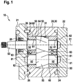
- Fig. 1 shows a longitudinal section of a gear machine 10 according to the invention.
- the gear machine 10 comprises a housing 20, which consists of a main body 30; a drive cover 21 and an end cover 22 is composed, which preferably consist of aluminum or gray cast iron.
- the drive and the end cover 21; 22 abut on flat end surfaces at the opposite ends of the main body 30, wherein at the end faces O-rings 24 are provided made of an elastomer, so that no pressure fluid can escape from the corresponding joint.
- the drive and the end cover 21; 22 are aligned over cylindrical pins 26 relative to the main body 30 and screwed (not shown) with these bolts firmly.
- two gears 50 are rotatably received with respect to an associated axis of rotation 51, wherein the gears 50 mesh with each other in external engagement.
- the aforementioned axes of rotation 51 run parallel to one another.
- the gears 50 are present helically toothed, but they can also be formed straight toothed. It should be noted that the invention underlying Kavitationsproblematik occurs primarily in helical gears.
- the two gears 50 have on both sides of a circular cylindrical bearing pin 52 which is rotatably mounted in a bearing shell 61 made of a sliding bearing material such as brass or bronze, wherein the bearing shell 61 is in turn firmly received in an associated bearing body 60 made of steel.
- each bearing pin 52 is associated with a separate part of the bearing body 60, wherein two adjacent parts abut each other on flat surfaces and are aligned by means of a cylindrical pin 26 to each other.
- the bearing body 60 may also be integrally formed.
- the bearing bodies 60 are pressed by the pressure of the pressurized fluid, for example hydraulic oil, in the gear machine 10 against the flat side surfaces 55 of the gears 50 to effect a lateral sealing of the gears 50.
- the pressurized fluid acts In this case, in a pressure field on the bearing body 60, which is bounded by an associated axial seal 62.
- One of the bearing journals 52 of a toothed wheel 50 is formed integrally with a drive pin 53 which projects out of the housing 20 through the drive cover 21.
- the corresponding passage opening is sealed with a radial shaft sealing ring 25, so that no pressure fluid can escape.
- the drive pin 53 can be rotatably connected, for example, with the drive shaft of an electric motor (not shown) when the gear machine 10 is operated as a pump.
- the inner circumferential surface 31 of the main body 30 has a constant cross-sectional shape along the axes of rotation 51 prior to the run-in process, which is adapted to the circular cylindrical tip diameter of the gears 50 with very little play.
- the pressure equalization land 64 is disposed opposite to the side surface 55 of an associated gear 50 and opposite to the inner peripheral surface 31 of the housing 20.
- Fig. 2 shows a cross section of a gear machine according to the invention 10.
- the high and the low pressure port 32; 33 are disposed opposite to the housing 20, having a common center axis 34 along which they have a constant cross-sectional shape.
- the high-pressure port 32 preferably has a circular cross-sectional shape, wherein the cross-sectional shape of the low-pressure port 33 deviates according to the invention from the circular shape.
- the already mentioned pressure compensating bevel 64 extends from the high pressure port 32 in the direction of the low pressure port 33. It has an end 65 which is arranged at a distance from the low pressure port 33.
- the gears 50 are acted upon by a hydraulic force 84, which presses its tooth tips 56 against the inner circumferential surface 31 of the housing 20 in a sealing region 11 on the low-pressure connection 34. Only there takes place at the tooth tips 56 a sealing contact with the housing 20. The remaining tooth tips 56 run with a small distance to the inner peripheral surface 31 to the housing 20 so that there pressure fluid between the interdental spaces 54 can be replaced.
- the Druckausticiansfase 64 may be present as shown only on one side of the gears 50, but it may also be provided on both sides of the gears 50. In the latter case is to be considered in helical gears 50 that the two pressure equalization bevels 64 must be designed to have different lengths, so that they end at the same tooth of the associated gear 50.
- Fig. 3 shows a rough schematic front view of the gears 50 and the bearing body 60, wherein the ideal shape of the low pressure port 33 is shown.
- the viewing direction is parallel to the central axis of the low-pressure connection 33, so that its cross-sectional shape coincides with the cutting edge 85 with the inner peripheral surface of the housing.
- the two imaginary boundary lines 80 run parallel to the helical contact lines 83 between the tooth tips of the gears 50 and the inner peripheral surface of the housing.
- the boundary lines 80 therefore extend on the inner peripheral surface of the housing.
- the border lines 80 each begin at the end 65 of an associated pressure equalization bevel 64 on the bearing body 60.
- the cross-sectional shape of the low-pressure connection 33 runs parallel to these in the region of the boundary lines 80.
- the minimum distance 81 from the boundary lines 80 is therefore the same everywhere, so that a maximum cross-sectional area of the low-pressure connection 33 covering the toothed wheels results.
- This cross-sectional area is in Fig. 3 hatched marked and marked with the reference numeral 79.
- the cross-sectional shape of the low pressure port 33 is aligned with the side surfaces 55 of the gears 50. In gears 50 with a very large helix angle, it may happen that the low pressure port 33, the in Fig. 3 right side surface 55 of the gears 50 no longer covered.
- FIG. 3 an imaginary low-pressure port 82 is shown, which has the same minimum distance 81 to the boundary lines 80.
- the corresponding circle 82 covers the bearing bodies 60, the corresponding surface section 78 not counting the cross-sectional area 79 covering the toothed wheels 50.
- the fraction of the hatched area 79 detected by the circle 82 is significantly smaller than the hatched area 79 itself, so that the condition according to the characterizing portion of claim 1 is satisfied.
- the minimum distance 81 between the low pressure port 33 and the boundary line 80 is at least one pitch (No. 57 in FIG Fig. 2 ) of the gears, wherein it is preferably selected to be slightly larger, so that regardless of the rotational position of the gears at least one tooth head completely rests against the inner peripheral surface of the housing.
- Fig. 4 shows a front view of the low pressure port 33 according to a first embodiment of the invention.
- the viewing direction is parallel to the central axis of the low pressure port 33.
- the two boundary lines 80 and the two side surfaces 55 of the gears are shown by dash-dotted lines.
- the cross-sectional shape of the low-pressure connection 33 has two first straight lines 70, which run essentially parallel to the associated boundary line 80.
- the two first straight lines 70 are connected by two second straight lines 71, which are arranged in alignment with the side surfaces 55 of the gears. If the gears have a very large width and / or a very large helix angle, it can occur that the first two lines 70 intersect in the area of the gears. In this case, the in Fig. 4 right straight 71.
- the corners between the first and second straight lines 70; 71 are rounded 74, so that the present low pressure connection can be easily made with an end mill.
- the corner radius 74 is, for example, 5 mm or 7.5 mm. On the rounding 74 but can also be dispensed with.
- the low pressure port 33 according to the first embodiment according to Fig. 4 covered with its entire cross-sectional area 79, the gears.
- the corresponding cross-sectional shape is mirror-symmetrical with respect to a plane of symmetry 86 which contains the central axis of the low-pressure connection 33.
- Fig. 5 shows a front view of the low pressure port 33 according to a second embodiment of the invention. Except for the differences described below, this embodiment is consistent with the first embodiment Fig. 4 so that reference is made to the corresponding statements. The viewing direction of Fig. 5 agrees with the one of Fig. 4 match.
- the second straight lines were replaced by arcs 73, which are arched outward.
- the radius of in Fig. 5 Left circular arc 73 corresponds to the radius of the passage opening, which has a standardized flange with a circular passage opening.
- the entire width of the low-pressure port 33 is preferably equal to or smaller than twice the said radius.
- the present low-pressure port 33 covers with the areas 78 and the bearing body of the gear machine.
- the gear cross-sectional cross-sectional area of the low pressure port 33 is the in Fig. 5 hatched area 79.
- Fig. 6 shows a front view of the low pressure port 33 according to a third embodiment of the invention. The viewing direction agrees with that of the 4 and 5 match.
- This low pressure port 33 is formed by two circular holes 76 which overlap.
- the corresponding cross-sectional shape is therefore composed of two circles 76 that overlap, having offset centers 77.
- the centers 77 are arranged on the plane of symmetry 86 of the low-pressure connection 33.
- three or more circles 76 may be provided, wherein two or three circles, the optimum compromise between manufacturing costs and the gear cross-sectional area 79 of the low pressure port 33 result.
Landscapes
- Engineering & Computer Science (AREA)
- Mechanical Engineering (AREA)
- General Engineering & Computer Science (AREA)
- Rotary Pumps (AREA)
- Hydraulic Motors (AREA)
- Gear Transmission (AREA)
Description
Die Erfindung betrifft eine Zahnradmaschine gemäß dem Oberbegriff von Anspruch 1.The invention relates to a gear machine according to the preamble of claim 1.
Aus der
Wenn die Zahnradmaschine als Pumpe betrieben wird, wird eines der Zahnräder beispielsweise mit einem Elektromotor in Drehbewegung versetzt, wobei Druckfluid, insbesondere Hydrauliköl, vom Nieder- zum Hochdruckanschluss fließt. Wenn die Zahnradmaschine als Motor betrieben wird, fließt das Druckfluid vom Hoch- zum Niederdruckanschluss, wobei die Zahnräder dadurch in Drehbewegung versetzt werden.When the gear machine is operated as a pump, one of the gears is rotated, for example, with an electric motor in rotary motion, wherein pressurized fluid, in particular hydraulic oil, flows from the low to the high pressure port. When the gear machine is operated as a motor, the pressurized fluid flows from the high to the low pressure port, thereby causing the gears to rotate.
Der Niederdruckanschluss weist in Richtung einer Mittelachse eine konstante Querschnittsform auf, die kreisförmig ausgebildet ist. Den entsprechenden Kreisdurchmesser versucht man am Niederdruckanschluss so groß wie möglich auszulegen, damit dort niedrige Strömungsgeschwindigkeiten des Druckfluids auftreten. Dadurch wird insbesondere bei Pumpen mit schnell laufenden Zahnrädern Kavitation am Niederdruckanschluss vermieden.The low-pressure connection has a constant cross-sectional shape in the direction of a central axis, which is circular. The corresponding circle diameter is attempted to be as large as possible at the low-pressure connection so that low flow velocities of the pressure fluid occur there. This avoids cavitation at the low-pressure connection, especially for pumps with high-speed gears.
Der Durchmesser des Niederdruckanschlusses kann dabei nur so weit gesteigert werden, wie an den Zahnköpfen der Zahnräder noch immer eine ausreichende Abdichtung zwischen dem Hoch- und dem Niederdruckanschluss gegeben ist.The diameter of the low-pressure connection can only be increased so far as there is still a sufficient seal between the high and the low pressure connection is given to the tooth tips of the gears.
In diesem Zusammenhang ist auf die Druckausgleichsfase an den Lagerkörpern hinzuweisen. Die Lagerkörper sind zu beiden Seiten neben den Zahnrädern angeordnet und werden vom Druckfluid dichtend gegen die Seitenflächen der Zahnräder gedrückt. Dabei sind die Zahnräder mit kreiszylindrischen Lagerzapfen in den Lagerkörpern gelagert. Der Lagerkörper auf einer Seite der Zahnräder kann einstückig ausgebildet sein, es ist aber genauso gut denkbar, jedem Zahnrad ein gesondertes Teil des Lagerkörpers zuzuordnen.In this context, reference should be made to the pressure equalization bevel on the bearing bodies. The bearing bodies are arranged on both sides next to the gears and are pressed by the pressure fluid sealingly against the side surfaces of the gears. The gears are mounted with circular cylindrical bearing pin in the bearing bodies. The bearing body on one side of the gears may be integrally formed, but it is equally conceivable to assign each gear a separate part of the bearing body.
Jedem Zahnrad ist wenigstens eine Druckausgleichsfase an den Lagerkörpern zugeordnet, die gegenüberliegend zu den Seitenflächen der Zahnräder und der Innenumfangsfläche angeordnet ist. Die Innenumfangsfläche ist dabei die Fläche, an denen die Zahnköpfe der Zahnräder dichtend anliegen. Die Druckausgleichsfase erstreckt sich vom Hochdruckanschluss in Richtung des Niederdruckanschlusses. In allen Zahnzwischenräumen der Zahnräder, die der Druckausgleichsfase gegenüber liegen, herrscht daher der Druck am Hochdruckanschluss, so dass die Zahnräder mit einer gut vorhersehbaren Kraft dichtend gegen die Innenumfangsfläche des Gehäuses im Bereich des Niederdruckanschlusses gedrückt werden, um dort eine Abdichtung zu bewirken.Each gear is associated with at least one Druckausgleichsfase on the bearing bodies, which is arranged opposite to the side surfaces of the gears and the inner peripheral surface. The inner peripheral surface is the surface against which the tooth tips of the gear wheels sealingly abut. The pressure equalization bevel extends from the high pressure port towards the low pressure port. In all interdental spaces of the gears, which are the Druckausgleichsfase opposite, there is therefore the pressure at the high pressure port, so that the gears are pressed with a good predictable force sealing against the inner peripheral surface of the housing in the region of the low pressure port to effect a seal there.
Bei der Bemessung des Durchmessers des Niederdruckanschlusses muss sichergestellt werden, dass in keiner Drehstellung der Zahnräder über die Zahnzwischenräume eine Fluidaustauschverbindung zwischen der Druckausgleichsfase und dem Niederdruckanschluss besteht.When dimensioning the diameter of the low-pressure connection, it must be ensured that there is no fluid exchange connection between the pressure equalization phase and the low-pressure connection in any rotational position of the gears via the interdental spaces.
Aus der
Die Aufgabe der Erfindung besteht darin, bei schnell drehenden Zahnradmaschinen, insbesondere Pumpen, Kavitation am Niederdruckanschluss zu vermeiden bzw. erst bei höheren Drehzahlen der Zahnräder einsetzen zu lassen.The object of the invention is to avoid at high-speed gear machines, especially pumps, cavitation at the low-pressure connection or to use only at higher speeds of the gears.
Gemäß dem selbständigen Anspruch wird diese Aufgabe dadurch gelöst, dass beiden Zahnrädern an der Innenumfangsfläche des Gehäuses eine gedachte Grenzlinie zugeordnet ist, welche das Ende der Druckausgleichsfase schneidet, wobei sie parallel zur Berührlinie zwischen den Zahnköpfen der Zahnräder und der Innenumfangsfläche verläuft, wobei die Schnittkante zwischen den beiden Grenzlinien angeordnet ist, wobei der minimale Abstand zwischen der Schnittkante und den Grenzlinien wenigstens einen Teilungsabstand der Zahnräder beträgt, wobei die Querschnittsform des Niederdruckanschlusses derart von der Kreisform abweicht, dass seine die Zahnräder überdeckende Querschnittsfläche größer ist als die die Zahnräder überdeckende Querschnittsfläche eines gedachten kreisförmigen Niederdruckanschlusses, der denselben minimalen Abstand zu den Grenzlinien aufweist. Soweit einem Zahnrad zwei Druckausgleichsfasen zugeordnet sind, sind diese vorzugsweise so ausgebildet, dass diese die gleiche Grenzlinie definieren. Ist dies ausnahmsweise nicht der Fall, so ist die Grenzlinie maßgebend, die den geringsten Abstand zum Niederdruckanschluss aufweist.According to the independent claim, this object is achieved in that both gears on the inner peripheral surface of the housing is associated with an imaginary boundary line which intersects the end of the Druckausgleichsfase, wherein it is parallel to the line of contact between the tooth tips of the gears and the inner peripheral surface, wherein the cutting edge between the two boundary lines is arranged, wherein the minimum distance between the cutting edge and the boundary lines is at least one pitch of the gears, wherein the cross-sectional shape of the low pressure port deviates from the circular shape such that its cross-sectional area covering the gears is greater than the cross-sectional area of an imaginary one covering the gears circular low pressure port, which has the same minimum distance to the boundary lines. As far as a gear two Druckausgleichsfasen are assigned, they are preferably designed so that they define the same boundary line. If this is not the case in exceptional cases, then the boundary line which has the smallest distance to the low-pressure connection is decisive.
Die vorgeschlagene Zahnradmaschine besitzt einen Niederdruckanschluss, der gegenüber dem Stand der Technik eine größere Querschnittsfläche aufweist. Dadurch werden die Strömungsgeschwindigkeiten am Niederdruckanschluss herabgesetzt, so dass Kavitation erst bei höheren Drehzahlen der Zahnräder auftritt.The proposed gear machine has a low-pressure port, which has a larger cross-sectional area than the prior art. As a result, the flow velocities are reduced at the low pressure port, so that cavitation occurs only at higher speeds of the gears.
Anzumerken ist, dass der genannte minimale Abstand entlang der Innenumfangsfläche des Gehäuses gemessen wird und zwar in Umfangsrichtung bezüglich der Drehachse des betreffenden Zahnrades. Gleiches trifft auf den Teilungsabstand der Zahnräder, also den Abstand zweier Zahnköpfe, zu.It should be noted that said minimum distance along the inner peripheral surface of the housing is measured, namely in the circumferential direction with respect to the axis of rotation of the respective gear. The same applies to the pitch of the gears, so the distance between two tooth heads, too.
In den abhängigen Ansprüchen sind vorteilhafte Weiterbildungen und Verbesserungen der Erfindung angegeben.In the dependent claims advantageous refinements and improvements of the invention are given.
Die Querschnittsform des Niederdruckanschlusses kann so ausgebildet sein, dass die Schnittkante einen konstanten Abstand zur zugeordneten Grenzlinie aufweist.The cross-sectional shape of the low-pressure connection may be formed so that the cutting edge has a constant distance to the associated boundary line.
Hierdurch ergibt sich ein Niederdruckanschluss, der die größtmögliche Querschnittsfläche aufweist.This results in a low-pressure connection, which has the largest possible cross-sectional area.
Die Querschnittsform des Niederdruckanschlusses kann zwei erste Geraden aufweisen, die jeweils im Wesentlichen parallel zu einer zugeordneten Grenzlinie verlaufen. Die ersten Geraden können deutlich einfacher hergestellt werden, als die oben beschriebene ideale Querschnittsform. Soweit schräg verzahnte Zahnräder zum Einsatz kommen, verläuft die Schnittkante zwischen der Innenumfangsfläche und dem Niederdruckanschluss nicht mehr ganz genau parallel zu den Grenzlinien. Die Abweichung ist aber so gering, dass keine nennenswerte Verschlechterung hinsichtlich der Kavitationsentstehung zu befürchten ist. Wenn gerade verzahnte Zahnräder zum Einsatz kommen, wird der oben vorgeschlagene Idealzustand verwirklicht.The cross-sectional shape of the low pressure port may include two first straight lines each extending substantially parallel to an associated boundary. The first straight lines can be made much simpler than the ideal cross-sectional shape described above. As far as helical gears are used, the cutting edge between the inner peripheral surface and the low-pressure connection no longer runs exactly parallel to the boundary lines. However, the deviation is so small that no appreciable deterioration in terms of cavitation formation is to be feared. When even toothed gears are used, the ideal state proposed above is realized.
Die beiden ersten Geraden können durch wenigstens eine, vorzugsweise zwei, zweite Geraden verbunden sein, die fluchtend zu den Seitenflächen der Zahnräder verlaufen. Hierdurch ergibt sich eine größtmögliche Querschnittsfläche des Niederdruckanschlusses.The two first straight lines may be connected by at least one, preferably two, second straight lines which run in alignment with the side surfaces of the toothed wheels. This results in the largest possible cross-sectional area of the low-pressure connection.
Die zwei ersten Geraden können durch wenigstens eine, vorzugsweise zwei, Kreisbögen miteinander verbunden sein. Diese Querschnittsform wird bevorzugt dann verwendet, wenn am Niederdruckanschluss außen am Gehäuse ein genormter Flansch vorgesehen ist, der für eine kreisförmige Durchtrittsöffnung für das Druckfluid vorgesehen ist. Der größere der genannten Kreisbögen wird dabei vorzugsweise fluchtend zu der genormten kreisförmigen Durchtrittsöffnung ausgebildet, wobei er insbesondere den gleichen Radius aufweist.The two first straight lines can be connected to one another by at least one, preferably two, circular arcs. This cross-sectional shape is preferably used when a standardized flange is provided at the low pressure port outside the housing, which is provided for a circular passage opening for the pressurized fluid. The larger of said arcs is preferably formed in alignment with the standardized circular passage opening, in particular having the same radius.
Die Querschnittsform des Niederdruckanschlusses kann verrundete Ecken aufweisen, damit er einfach mit einem Schaftfräser hergestellt werden kann. Der Radius der Ecken entspricht dabei dem Radius des Schaftfräsers.The cross-sectional shape of the low pressure port may have rounded corners, so that it can be easily manufactured with an end mill. The radius of the corners corresponds to the radius of the end mill.
Die Querschnittsform des Niederdruckanschlusses kann durch mehrere, vorzugsweise zwei oder drei, sich überschneidende Kreise gebildet werden, die zueinander versetzte Mittelpunkte aufweisen. Hierdurch soll gegenüber den oben beschriebenen Querschnittsformen eine weitere Vereinfachung der Herstellung erreicht werden. Dabei ist insbesondere daran gedacht, die genannten Kreise durch gesonderte Bohrbearbeitungen herzustellen, wobei die Drehachse der betreffenden Bohrer versetzt zueinander angeordnet sind. Mit den bevorzugten zwei oder drei Bohrungen kann bereits eine deutliche Verbesserung hinsichtlich der Kavitationsneigung erreicht werden.The cross-sectional shape of the low-pressure connection can be formed by a plurality, preferably two or three, intersecting circles which offset one another Have midpoints. As a result, compared to the cross-sectional shapes described above, a further simplification of the production is to be achieved. In particular, it is intended to produce said circles by separate drilling operations, wherein the axis of rotation of the respective drill are offset from each other. With the preferred two or three holes already a significant improvement in cavitation tendency can be achieved.
Der Niederdruckanschluss kann wenigstens einen Lagerkörper überdecken. Für die Funktion der Zahnradmaschine ist es unschädlich, wenn der Niederdruckanschluss die Lagerkörper überdeckt. Hierdurch kann zwar unmittelbar keine Verbesserung des Kavitationsverhaltens erreicht werden. Es ist jedoch einfacher möglich, die Querschnittsform des Niederdruckanschlusses im Bereich der Zahnräder optimal an die Grenzlinien anzunähern.The low-pressure connection can cover at least one bearing body. For the function of the gear machine, it is harmless if the low-pressure connection covers the bearing body. Although this does not directly improve the cavitation behavior can be achieved. However, it is easier to approach the cross-sectional shape of the low pressure port in the area of the gears optimally to the boundary lines.
Die Erfindung wird im Folgenden anhand der beigefügten Zeichnungen näher erläutert. Es stellt dar:
- Fig. 1
- einen Längsschnitt einer erfindungsgemäßen Zahnradmaschine;
- Fig. 2
- einen Querschnitt einer erfindungsgemäßen Zahnradmaschine;
- Fig. 3
- eine grobschematische Vorderansicht der Zahnräder und der Lagerkörper, wobei die ideale Form des Niederdruckanschlusses gezeigt ist;
- Fig. 4
- eine Vorderansicht des Niederdruckanschlusses gemäß einer ersten Ausführungsform der Erfindung;
- Fig. 5
- eine Vorderansicht des Niederdruckanschlusses gemäß einer zweiten Ausführungsform der Erfindung; und
- Fig. 6
- eine Vorderansicht des Niederdruckanschlusses gemäß einer dritten Ausführungsform der Erfindung.
- Fig. 1
- a longitudinal section of a gear machine according to the invention;
- Fig. 2
- a cross section of a gear machine according to the invention;
- Fig. 3
- a rough schematic front view of the gears and the bearing body, wherein the ideal shape of the low pressure port is shown;
- Fig. 4
- a front view of the low pressure port according to a first embodiment of the invention;
- Fig. 5
- a front view of the low pressure port according to a second embodiment of the invention; and
- Fig. 6
- a front view of the low pressure port according to a third embodiment of the invention.
In dem Gehäuse 20 sind zwei Zahnräder 50 bezüglich einer zugeordneten Drehachse 51 drehbar aufgenommen, wobei die Zahnräder 50 im Außeneingriff miteinander kämmen. Die genannten Drehachsen 51 verlaufen parallel zueinander. Die Zahnräder 50 sind vorliegend schräg verzahnt, sie können aber auch gerade verzahnt ausgebildet sein. Dabei ist anzumerken, dass die der Erfindung zugrunde liegende Kavitationsproblematik vorrangig bei schräg verzahnten Zahnrädern auftritt.In the housing 20, two
Die beiden Zahnräder 50 weisen auf beiden Seiten einen kreiszylindrischen Lagerzapfen 52 auf, der in einer Lagerschale 61 aus einem Gleitlagerwerkstoff wie Messing oder Bronze drehbar gelagert ist, wobei die Lagerschale 61 wiederum in einem zugeordneten Lagerkörper 60 aus Stahl fest aufgenommen ist. Bei der vorliegenden Ausführungsform ist jedem Lagerzapfen 52 ein gesondertes Teil des Lagerkörpers 60 zugeordnet, wobei zwei benachbarte Teile an ebenen Flächen aneinander anliegen und mittels eines Zylinderstiftes 26 zueinander ausgerichtet sind. Die Lagerkörper 60 können auch einstückig ausgebildet sein. Die Lagerkörper 60 werden von dem Druck des Druckfluids, beispielsweise Hydrauliköl, in der Zahnradmaschine 10 gegen die ebenen Seitenflächen 55 der Zahnräder 50 gedrückt, um eine seitliche Abdichtung der Zahnräder 50 zu bewirken. Das Druckfluid wirkt dabei in einem Druckfeld auf den Lagerkörper 60 ein, welches von einer zugeordneten Axialdichtung 62 begrenzt wird.The two gears 50 have on both sides of a circular
Einer der Lagerzapfen 52 eines Zahnrades 50 ist einstückig mit einem Antriebszapfen 53 ausgebildet, der durch den Antriebsdeckel 21 hindurch aus dem Gehäuse 20 herausragt. Die entsprechende Durchtrittsöffnung ist mit einem Radialwellendichtring 25 dicht verschlossen, so dass kein Druckfluid austreten kann. Der Antriebszapfen 53 kann beispielsweise mit der Antriebswelle eines (nicht dargestellten) Elektromotors drehfest verbunden werden, wenn die Zahnradmaschine 10 als Pumpe betrieben wird.One of the bearing
Die Innenumfangsfläche 31 des Hauptkörpers 30 weist vor dem Einlaufprozess entlang der Drehachsen 51 eine konstante Querschnittsform auf, die mit sehr geringem Spiel an den kreiszylindrischen Kopfkreisdurchmesser der Zahnräder 50 angepasst ist.The inner
Weiter ist auf die Druckausgleichsfase 64 an dem in
Die bereits angesprochene Druckausgleichsfase 64 erstreckt sich vom Hochdruckanschluss 32 in Richtung des Niederdruckanschlusses 33. Sie weist ein Ende 65 auf, das mit Abstand zum Niederdruckanschluss 33 angeordnet ist. In den Zahnzwischenräumen 54, die im Bereich der Druckausgleichsfase 64 angeordnet sind, herrscht daher überall ein Druck der gleich dem Druck am Hochdruckanschluss 32 ist. In den verbleibenden Zahnzwischenräumen herrscht ein geringerer Druck, was im Ergebnis dazu führt, dass auf die Zahnräder 50 eine hydraulische Kraft 84 einwirkt, die dessen Zahnköpfe 56 in einem Dichtbereich 11 am Niederdruckanschluss 34 gegen die Innenumfangsfläche 31 des Gehäuses 20 drückt. Nur dort findet an den Zahnköpfen 56 eine dichtende Anlage zum Gehäuse 20 statt. Die verbleibenden Zahnköpfe 56 laufen mit einem geringen Abstand zur Innenumfangsfläche 31 zum Gehäuse 20, so dass dort Druckfluid zwischen den Zahnzwischenräumen 54 ausgetauscht werden kann.The already mentioned
Die Druckausgleichsfase 64 kann wie vorliegend dargestellt nur auf einer Seite der Zahnräder 50 vorhanden sein, sie kann aber auch auf beiden Seiten der Zahnräder 50 vorgesehen sein. Im letzteren Fall ist bei schräg verzahnten Zahnrädern 50 zu berücksichtigen, dass die beiden Druckausgleichsfasen 64 unterschiedlich lang ausgebildet sein müssen, damit sie am gleichen Zahn des zugeordneten Zahnrades 50 enden.The
Die beiden gedachten Grenzlinien 80 verlaufen parallel zu den schraubenlinienförmigen Berührlinien 83 zwischen den Zahnköpfen der Zahnräder 50 und der Innenumfangsfläche des Gehäuses. Die Grenzlinien 80 verlaufen daher auf der Innenumfangsfläche des Gehäuses. Die Grenzlinien 80 beginnen jeweils am Ende 65 einer zugeordneten Druckausgleichsfase 64 am Lagerkörper 60.The two
Die Querschnittsform des Niederdruckanschlusses 33 verläuft im Bereich der Grenzlinien 80 parallel zu diesen. Der minimale Abstand 81 zu den Grenzlinien 80 ist daher überall gleich, so dass sich eine maximale die Zahnräder überdeckende Querschnittsfläche des Niederdruckanschlusses 33 ergibt. Diese Querschnittsfläche ist in
Im Übrigen verläuft die Querschnittsform des Niederdruckanschlusses 33 fluchtend zu den Seitenflächen 55 der Zahnräder 50. Bei Zahnrädern 50 mit sehr großem Schrägungswinkel kann es vorkommen, dass der Niederdruckanschluss 33 die in
Weiter ist in
Der minimale Abstand 81 zwischen dem Niederdruckanschluss 33 und der Grenzlinie 80 beträgt wenigstens einen Teilungsabstand (Nr. 57 in
Die Querschnittsform des Niederdruckanschlusses 33 weist zwei erste Geraden 70 auf, die im Wesentlichen parallel zur zugeordneten Grenzlinie 80 verlaufen. Die beiden ersten Geraden 70 sind durch zwei zweite Geraden 71 verbunden, die in einer Flucht mit den Seitenflächen 55 der Zahnräder angeordnet sind. Wenn die Zahnräder eine sehr große Breite und/oder einen sehr großen Schrägungswinkel aufweisen, kann es vorkommen, dass sich die beiden ersten Geraden 70 im Bereich der Zahnräder schneiden. In diesem Fall entfällt die in
Die Ecken zwischen den ersten und den zweiten Geraden 70; 71 sind verrundet 74, so dass der vorliegende Niederdruckanschluss einfach mit einem Schaftfräser hergestellt werden kann. Der Eckenradius 74 beträgt beispielsweise 5 mm oder 7,5 mm. Auf die Verrundung 74 kann aber auch verzichtet werden.The corners between the first and second
Der Niederdruckanschluss 33 gemäß der ersten Ausführungsform nach
Die zweiten Geraden wurden durch Kreisbögen 73, die nach außen gewölbt sind, ersetzt. Der Radius des in
Der vorliegende Niederdruckanschluss 33 überdeckt mit den Bereichen 78 auch die Lagerkörper der Zahnradmaschine. Die die Zahnräder überdeckende Querschnittsfläche des Niederdruckanschlusses 33 ist die in
Dieser Niederdruckanschluss 33 wird durch zwei kreisrunde Bohrungen 76 gebildet, die sich überschneiden. Die entsprechende Querschnittsform ist daher aus zwei Kreisen 76 zusammengesetzt, die sich überschneiden, wobei sie versetzte Mittelpunkte 77 aufweisen. Die Mittelpunkte 77 sind auf der Symmetrieebene 86 des Niederdruckanschlusses 33 angeordnet. Anstelle der dargestellten zwei Kreise 76 können auch drei oder mehr Kreise 76 vorgesehen sein, wobei zwei oder drei Kreise, den optimalen Kompromiss zwischen Herstellkosten und die Zahnräder überdeckende Querschnittsfläche 79 des Niederdruckanschlusses 33 ergeben.This
Der in
- 1010
- Zahnradmaschinegear machine
- 1111
- Dichtbereichsealing area
- 2020
- Gehäusecasing
- 2121
- Antriebsdeckeldrive cover
- 2222
- EnddeckelEnd covers
- 2323
- NiederdruckanschlussLow pressure port
- 2424
- O-RingO-ring
- 2525
- RadialwellendichtringRadial shaft seal
- 2626
- Zylinderstiftstraight pin
- 3030
- Hauptkörpermain body
- 3131
- InnenumfangsflächeInner circumferential surface
- 3232
- HochdruckanschlussHigh pressure port
- 3333
- NiederdruckanschlussLow pressure port
- 3434
- Mittelachse des Hoch- und des NiederdruckanschlussesCenter axis of the high and low pressure connection
- 5050
- Zahnradgear
- 5151
- Drehachse des ZahnradesRotary axis of the gear
- 5252
- Lagerzapfenpivot
- 5353
- Antriebszapfendrive journal
- 5454
- ZahnzwischenraumInterdental
- 5555
- Seitenflächeside surface
- 5656
- Zahnkopfaddendum
- 5757
- Teilungsabstandpitch
- 6060
- Lagerkörperbearing body
- 6161
- Lagerschalebearing shell
- 6262
- Axialdichtungaxial seal
- 6363
- Zylinderstiftstraight pin
- 6464
- DruckausgleichsfaseDruckausgleichsfase
- 6565
- Ende der DruckausgleichsfaseEnd of the pressure equalization phase
- 7070
- erste Geradefirst straight
- 7171
- zweite Geradesecond straight line
- 7373
- Kreisbogenarc
- 7474
- verrundete Eckerounded corner
- 7676
- Kreiscircle
- 7777
- Mittelpunkt des KreisesCenter of the circle
- 7878
- Bereich, der die Lagerkörper überdecktArea that covers the bearing bodies
- 7979
- die Zahnräder überdeckende Querschnittsflächethe gear cross-sectional area
- 8080
- Grenzlinieboundary line
- 8181
- minimaler Abstand zur Grenzlinieminimum distance to the borderline
- 8282
- Kreis mit gleichem minimalen Abstand zur GrenzlinieCircle with the same minimum distance to the borderline
- 8383
- Berührlinie zwischen Zahnkopf und Innenumfangsfläche des GehäusesTouch line between the tooth tip and the inner peripheral surface of the housing
- 8484
- hydraulische Krafthydraulic power
- 8585
- Schnittkantecutting edge
- 8686
- Symmetrieebeneplane of symmetry
Claims (8)
- Gear machine (10), in particular a pump or a motor, having two externally intermeshing gear wheels (50), which are enclosed by a housing (20), which comprises a high-pressure connection (32) and a low-pressure connection (33) situated opposite one another, the low-pressure connection (33) having a constant cross sectional shape in the direction of the central axis (34), said connection forming an intersection edge (85) with an inner circumferential face (31) of the housing (30) which bears tightly against the gear tooth tips (56) of the gear wheels (50), an optionally multipart bearing liner (60), in which the gear wheels (50) are rotatably supported, being arranged on both sides of each of the gear wheels (50), the bearing liners (60) bearing tightly on an associated lateral face (55) of the gear wheels (50), at least one pressure equalization chamfer (64) on the bearing liners (60) being assigned to each of the two gear wheels (50), said chamfer extending opposite the relevant gear wheel (50) and the inner circumferential face (31) from the high-pressure connection (32) in the direction of the low-pressure connection (33), where it has an end (65), characterized in that on the inner circumferential face (31) of the housing (20) a notional boundary line (80), which intersects the end (65) of the pressure equalization chamfer (64), is assigned to both gear wheels (50), said line running parallel to the line of contact (83) between the gear tooth tips (56) of the gear wheels (50) and the inner circumferential face (31), the intersection edge (85) being located between the two boundary lines (80), the minimum distance (81) between the intersection edge (85) and the boundary lines (80) being at least one pitch interval (57) of the gear wheels (50), the cross sectional shape of the low-pressure connection (33) deviating from the circular shape in such a way that its cross sectional area (79) overlapping the gear wheels (50) is greater than the cross sectional area of a notional, circular low-pressure connection (82) overlapping the gear wheels (50) at the same minimum distance (81) from the boundary lines (80).
- Gear machine according to Claim 1, wherein the cross sectional shape of the low-pressure connection (33) is formed so that the intersection edge (85) is at a constant distance (81) from the associated boundary line (80).
- Gear machine according to either of the preceding claims, wherein the cross sectional shape of the low-pressure connection (33) comprises two first straight lines (70), which each run substantially parallel to an associated boundary line (80).
- Gear machine according to Claim 3, wherein the two first straight lines (70) are connected by at least one, preferably two, second straight lines (71), which run in alignment with the lateral faces (55) of the gear wheels (50).
- Gear machine according to Claim 3, wherein the two first straight lines (70) are connected to one another by at least one, preferably two, circular arcs (73).
- Gear machine according to one of the preceding claims, wherein the cross sectional shape of the low-pressure connection (33) has rounded corners (74).
- Gear machine according to Claim 1 or 2, wherein the cross sectional shape of the low-pressure connection (33) is formed by more than one, preferably two or three, overlapping circles (76), which have centers (77) offset in relation to one another.
- Gear machine according to one of the preceding claims, wherein the low-pressure connection (33) overlaps at least one bearing liner (60).
Applications Claiming Priority (1)
| Application Number | Priority Date | Filing Date | Title |
|---|---|---|---|
| DE102012217115.0A DE102012217115A1 (en) | 2012-09-24 | 2012-09-24 | Gear machine with deviating from the circular low pressure port |
Publications (3)
| Publication Number | Publication Date |
|---|---|
| EP2711552A2 EP2711552A2 (en) | 2014-03-26 |
| EP2711552A3 EP2711552A3 (en) | 2017-05-31 |
| EP2711552B1 true EP2711552B1 (en) | 2019-02-27 |
Family
ID=49036461
Family Applications (1)
| Application Number | Title | Priority Date | Filing Date |
|---|---|---|---|
| EP13181924.5A Active EP2711552B1 (en) | 2012-09-24 | 2013-08-28 | Geared machine with low pressure connection deviating from the circular form |
Country Status (3)
| Country | Link |
|---|---|
| US (1) | US9140258B2 (en) |
| EP (1) | EP2711552B1 (en) |
| DE (1) | DE102012217115A1 (en) |
Families Citing this family (5)
| Publication number | Priority date | Publication date | Assignee | Title |
|---|---|---|---|---|
| JP6464640B2 (en) * | 2014-09-30 | 2019-02-06 | ダイキン工業株式会社 | Gear pump or motor |
| WO2016147217A1 (en) * | 2015-03-17 | 2016-09-22 | 株式会社Tbk | Gear pump |
| JP2017223197A (en) * | 2016-06-17 | 2017-12-21 | 住友精密工業株式会社 | Hydraulic device |
| WO2021044570A1 (en) * | 2019-09-05 | 2021-03-11 | 株式会社島津製作所 | Helical gear pump, or helical gear motor |
| IT202300014397A1 (en) * | 2023-07-10 | 2025-01-10 | Marzocchi Pompe S P A | REVERSIBLE HYDRAULIC MACHINE WITH HELICAL TOOTHED GEAR WITH BILATERAL HYDRAULIC SYSTEM FOR BALANCING AXIAL FORCES. |
Family Cites Families (7)
| Publication number | Priority date | Publication date | Assignee | Title |
|---|---|---|---|---|
| GB1554262A (en) * | 1975-06-24 | 1979-10-17 | Kayaba Industry Co Ltd | Gear pump |
| DE2554105C2 (en) * | 1975-12-02 | 1984-04-05 | Robert Bosch Gmbh, 7000 Stuttgart | Gear machine (pump or motor) |
| JPS55101786A (en) * | 1979-01-26 | 1980-08-04 | Kayaba Ind Co Ltd | Construction of body bore in gear pump or motor |
| US5190450A (en) * | 1992-03-06 | 1993-03-02 | Eastman Kodak Company | Gear pump for high viscosity materials |
| JP3830313B2 (en) * | 1999-09-06 | 2006-10-04 | 株式会社ジェイテクト | Gear pump |
| DE102007031909A1 (en) * | 2007-07-09 | 2009-01-15 | Schwäbische Hüttenwerke Automotive GmbH & Co. KG | Rotary pump e.g. lubricating oil pump, for motor vehicle, has muzzle region formed such that cell base near rotation axis ends in overlapping by rotary drive of transport wheel, while cell region is still in overlap with sealing surface |
| DE102009012853A1 (en) | 2009-03-12 | 2010-09-16 | Robert Bosch Gmbh | Hydraulic gear machine |
-
2012
- 2012-09-24 DE DE102012217115.0A patent/DE102012217115A1/en not_active Withdrawn
-
2013
- 2013-08-28 EP EP13181924.5A patent/EP2711552B1/en active Active
- 2013-09-18 US US14/030,109 patent/US9140258B2/en active Active
Non-Patent Citations (1)
| Title |
|---|
| None * |
Also Published As
| Publication number | Publication date |
|---|---|
| DE102012217115A1 (en) | 2014-03-27 |
| US9140258B2 (en) | 2015-09-22 |
| EP2711552A2 (en) | 2014-03-26 |
| US20140086779A1 (en) | 2014-03-27 |
| EP2711552A3 (en) | 2017-05-31 |
Similar Documents
| Publication | Publication Date | Title |
|---|---|---|
| DE102011122642B4 (en) | Reversible gerotor pump | |
| EP2711552B1 (en) | Geared machine with low pressure connection deviating from the circular form | |
| DE19613833A1 (en) | Gear pump with meshing internal and external toothed wheels | |
| DE1553057C3 (en) | Rotary piston machine | |
| EP2672119B1 (en) | Geared machine with hydrodynamic and hydrostatic bearing pins | |
| EP0707686B1 (en) | Hydraulic gearwheel machine (pump or engine) in particular internal-gearwheel machine | |
| DE102016207093B4 (en) | Gear fluid machine | |
| DE102012206699B4 (en) | Gear machine with a trough-like recess on the outer surface of the housing | |
| DE10058883A1 (en) | Geared pump with hollow gear contains sickle-shaped space here filled out by first and second fillers in one or two pieces and on opposite sides of interposed filler pin. | |
| EP2657525B1 (en) | Gear machine with an axial seal stretching into the area of radial exterior surface of the correponding bearing support | |
| DE102005041579B4 (en) | Internal gear pump with filling piece | |
| DE102012216122A1 (en) | Fluid conveying device e.g. double external low pressure gear pump for conveying hydraulic oil, has pair of gears exhibiting same axle distance and different gear geometries to provide different pressures and/or volumetric flows | |
| DE102013202917A1 (en) | Geared machine, particularly gear pump or gear motor, has pressure chamber, in which pressure fluid having low particle concentration is present, and channel, through which pressure chamber is connected with axial force compensating groove | |
| DE102012209152A1 (en) | Gear machine e.g. pump is formed with recess with two portions extended in different directions, such that pressurized fluid pass into recess in direct contact with bearing sleeve and tooth space of associated gearwheel | |
| DE102004021216A1 (en) | High pressure gear type hydraulic pump has a central pinion meshing with an eccentric inner gear wheel supported on radial hydraulic pockets | |
| DE102014212255A1 (en) | External gear machine with bearing bodies, which are linearly slidably supported against each other | |
| EP2647845A2 (en) | Hydrostatic displacement machine with curved path of contact and edge line withdrawal | |
| DE102012209775A1 (en) | Gear wheel machine e.g. pump and electromotor, has wheels teeth comprising clamping surface arranged such that clamping surface does not contact force transferring tooth flank of gear wheels in all rotational positions of machine | |
| WO2008125106A1 (en) | Gerotor motor | |
| DE102013202606A1 (en) | Gear wheel machine e.g. gear motor, has sleeve comprising projection that extends in direction of rotational axis of wheels, where projection partially covers groove in each rotational position of sleeve with respect to body | |
| DE2134241A1 (en) | Multi-stage external rotary lobe machine for elastic working media | |
| EP2690252A1 (en) | Pompe à engrenages internes trochoïdes | |
| EP2713052B1 (en) | Geared machine with a groove for holding an entry ridge | |
| DE102012206698A1 (en) | Hydrostatic positive-displacement engine, has housing comprising housing portions extending in plane separating surface abutting each other, and plane separating surface incorporating rotational axes of gear wheels | |
| DE102013202918A1 (en) | Gear machine e.g. gear pump, has bearing portion that is rotatably arranged with respect to rotation axis, and slidably received in housing in direction of rotation axis |
Legal Events
| Date | Code | Title | Description |
|---|---|---|---|
| PUAI | Public reference made under article 153(3) epc to a published international application that has entered the european phase |
Free format text: ORIGINAL CODE: 0009012 |
|
| AK | Designated contracting states |
Kind code of ref document: A2 Designated state(s): AL AT BE BG CH CY CZ DE DK EE ES FI FR GB GR HR HU IE IS IT LI LT LU LV MC MK MT NL NO PL PT RO RS SE SI SK SM TR |
|
| AX | Request for extension of the european patent |
Extension state: BA ME |
|
| PUAL | Search report despatched |
Free format text: ORIGINAL CODE: 0009013 |
|
| AK | Designated contracting states |
Kind code of ref document: A3 Designated state(s): AL AT BE BG CH CY CZ DE DK EE ES FI FR GB GR HR HU IE IS IT LI LT LU LV MC MK MT NL NO PL PT RO RS SE SI SK SM TR |
|
| AX | Request for extension of the european patent |
Extension state: BA ME |
|
| RIC1 | Information provided on ipc code assigned before grant |
Ipc: F04C 15/06 20060101ALI20170421BHEP Ipc: F04C 2/08 20060101ALN20170421BHEP Ipc: F04C 2/18 20060101AFI20170421BHEP |
|
| STAA | Information on the status of an ep patent application or granted ep patent |
Free format text: STATUS: REQUEST FOR EXAMINATION WAS MADE |
|
| 17P | Request for examination filed |
Effective date: 20171130 |
|
| RBV | Designated contracting states (corrected) |
Designated state(s): AL AT BE BG CH CY CZ DE DK EE ES FI FR GB GR HR HU IE IS IT LI LT LU LV MC MK MT NL NO PL PT RO RS SE SI SK SM TR |
|
| RIC1 | Information provided on ipc code assigned before grant |
Ipc: F04C 15/06 20060101ALI20180917BHEP Ipc: F04C 2/08 20060101ALN20180917BHEP Ipc: F04C 2/18 20060101AFI20180917BHEP |
|
| GRAP | Despatch of communication of intention to grant a patent |
Free format text: ORIGINAL CODE: EPIDOSNIGR1 |
|
| STAA | Information on the status of an ep patent application or granted ep patent |
Free format text: STATUS: GRANT OF PATENT IS INTENDED |
|
| INTG | Intention to grant announced |
Effective date: 20181115 |
|
| GRAS | Grant fee paid |
Free format text: ORIGINAL CODE: EPIDOSNIGR3 |
|
| GRAA | (expected) grant |
Free format text: ORIGINAL CODE: 0009210 |
|
| STAA | Information on the status of an ep patent application or granted ep patent |
Free format text: STATUS: THE PATENT HAS BEEN GRANTED |
|
| AK | Designated contracting states |
Kind code of ref document: B1 Designated state(s): AL AT BE BG CH CY CZ DE DK EE ES FI FR GB GR HR HU IE IS IT LI LT LU LV MC MK MT NL NO PL PT RO RS SE SI SK SM TR |
|
| REG | Reference to a national code |
Ref country code: GB Ref legal event code: FG4D Free format text: NOT ENGLISH |
|
| REG | Reference to a national code |
Ref country code: CH Ref legal event code: EP |
|
| REG | Reference to a national code |
Ref country code: AT Ref legal event code: REF Ref document number: 1101763 Country of ref document: AT Kind code of ref document: T Effective date: 20190315 |
|
| REG | Reference to a national code |
Ref country code: IE Ref legal event code: FG4D Free format text: LANGUAGE OF EP DOCUMENT: GERMAN |
|
| REG | Reference to a national code |
Ref country code: DE Ref legal event code: R096 Ref document number: 502013012273 Country of ref document: DE |
|
| REG | Reference to a national code |
Ref country code: NL Ref legal event code: MP Effective date: 20190227 |
|
| REG | Reference to a national code |
Ref country code: LT Ref legal event code: MG4D |
|
| PG25 | Lapsed in a contracting state [announced via postgrant information from national office to epo] |
Ref country code: NO Free format text: LAPSE BECAUSE OF FAILURE TO SUBMIT A TRANSLATION OF THE DESCRIPTION OR TO PAY THE FEE WITHIN THE PRESCRIBED TIME-LIMIT Effective date: 20190527 Ref country code: PT Free format text: LAPSE BECAUSE OF FAILURE TO SUBMIT A TRANSLATION OF THE DESCRIPTION OR TO PAY THE FEE WITHIN THE PRESCRIBED TIME-LIMIT Effective date: 20190627 Ref country code: FI Free format text: LAPSE BECAUSE OF FAILURE TO SUBMIT A TRANSLATION OF THE DESCRIPTION OR TO PAY THE FEE WITHIN THE PRESCRIBED TIME-LIMIT Effective date: 20190227 Ref country code: SE Free format text: LAPSE BECAUSE OF FAILURE TO SUBMIT A TRANSLATION OF THE DESCRIPTION OR TO PAY THE FEE WITHIN THE PRESCRIBED TIME-LIMIT Effective date: 20190227 Ref country code: LT Free format text: LAPSE BECAUSE OF FAILURE TO SUBMIT A TRANSLATION OF THE DESCRIPTION OR TO PAY THE FEE WITHIN THE PRESCRIBED TIME-LIMIT Effective date: 20190227 Ref country code: NL Free format text: LAPSE BECAUSE OF FAILURE TO SUBMIT A TRANSLATION OF THE DESCRIPTION OR TO PAY THE FEE WITHIN THE PRESCRIBED TIME-LIMIT Effective date: 20190227 |
|
| PG25 | Lapsed in a contracting state [announced via postgrant information from national office to epo] |
Ref country code: RS Free format text: LAPSE BECAUSE OF FAILURE TO SUBMIT A TRANSLATION OF THE DESCRIPTION OR TO PAY THE FEE WITHIN THE PRESCRIBED TIME-LIMIT Effective date: 20190227 Ref country code: GR Free format text: LAPSE BECAUSE OF FAILURE TO SUBMIT A TRANSLATION OF THE DESCRIPTION OR TO PAY THE FEE WITHIN THE PRESCRIBED TIME-LIMIT Effective date: 20190528 Ref country code: HR Free format text: LAPSE BECAUSE OF FAILURE TO SUBMIT A TRANSLATION OF THE DESCRIPTION OR TO PAY THE FEE WITHIN THE PRESCRIBED TIME-LIMIT Effective date: 20190227 Ref country code: LV Free format text: LAPSE BECAUSE OF FAILURE TO SUBMIT A TRANSLATION OF THE DESCRIPTION OR TO PAY THE FEE WITHIN THE PRESCRIBED TIME-LIMIT Effective date: 20190227 Ref country code: IS Free format text: LAPSE BECAUSE OF FAILURE TO SUBMIT A TRANSLATION OF THE DESCRIPTION OR TO PAY THE FEE WITHIN THE PRESCRIBED TIME-LIMIT Effective date: 20190627 Ref country code: BG Free format text: LAPSE BECAUSE OF FAILURE TO SUBMIT A TRANSLATION OF THE DESCRIPTION OR TO PAY THE FEE WITHIN THE PRESCRIBED TIME-LIMIT Effective date: 20190527 |
|
| PG25 | Lapsed in a contracting state [announced via postgrant information from national office to epo] |
Ref country code: SK Free format text: LAPSE BECAUSE OF FAILURE TO SUBMIT A TRANSLATION OF THE DESCRIPTION OR TO PAY THE FEE WITHIN THE PRESCRIBED TIME-LIMIT Effective date: 20190227 Ref country code: RO Free format text: LAPSE BECAUSE OF FAILURE TO SUBMIT A TRANSLATION OF THE DESCRIPTION OR TO PAY THE FEE WITHIN THE PRESCRIBED TIME-LIMIT Effective date: 20190227 Ref country code: DK Free format text: LAPSE BECAUSE OF FAILURE TO SUBMIT A TRANSLATION OF THE DESCRIPTION OR TO PAY THE FEE WITHIN THE PRESCRIBED TIME-LIMIT Effective date: 20190227 Ref country code: EE Free format text: LAPSE BECAUSE OF FAILURE TO SUBMIT A TRANSLATION OF THE DESCRIPTION OR TO PAY THE FEE WITHIN THE PRESCRIBED TIME-LIMIT Effective date: 20190227 Ref country code: AL Free format text: LAPSE BECAUSE OF FAILURE TO SUBMIT A TRANSLATION OF THE DESCRIPTION OR TO PAY THE FEE WITHIN THE PRESCRIBED TIME-LIMIT Effective date: 20190227 Ref country code: ES Free format text: LAPSE BECAUSE OF FAILURE TO SUBMIT A TRANSLATION OF THE DESCRIPTION OR TO PAY THE FEE WITHIN THE PRESCRIBED TIME-LIMIT Effective date: 20190227 Ref country code: CZ Free format text: LAPSE BECAUSE OF FAILURE TO SUBMIT A TRANSLATION OF THE DESCRIPTION OR TO PAY THE FEE WITHIN THE PRESCRIBED TIME-LIMIT Effective date: 20190227 |
|
| REG | Reference to a national code |
Ref country code: DE Ref legal event code: R097 Ref document number: 502013012273 Country of ref document: DE |
|
| PG25 | Lapsed in a contracting state [announced via postgrant information from national office to epo] |
Ref country code: PL Free format text: LAPSE BECAUSE OF FAILURE TO SUBMIT A TRANSLATION OF THE DESCRIPTION OR TO PAY THE FEE WITHIN THE PRESCRIBED TIME-LIMIT Effective date: 20190227 Ref country code: SM Free format text: LAPSE BECAUSE OF FAILURE TO SUBMIT A TRANSLATION OF THE DESCRIPTION OR TO PAY THE FEE WITHIN THE PRESCRIBED TIME-LIMIT Effective date: 20190227 |
|
| PLBE | No opposition filed within time limit |
Free format text: ORIGINAL CODE: 0009261 |
|
| STAA | Information on the status of an ep patent application or granted ep patent |
Free format text: STATUS: NO OPPOSITION FILED WITHIN TIME LIMIT |
|
| 26N | No opposition filed |
Effective date: 20191128 |
|
| PG25 | Lapsed in a contracting state [announced via postgrant information from national office to epo] |
Ref country code: SI Free format text: LAPSE BECAUSE OF FAILURE TO SUBMIT A TRANSLATION OF THE DESCRIPTION OR TO PAY THE FEE WITHIN THE PRESCRIBED TIME-LIMIT Effective date: 20190227 |
|
| PG25 | Lapsed in a contracting state [announced via postgrant information from national office to epo] |
Ref country code: TR Free format text: LAPSE BECAUSE OF FAILURE TO SUBMIT A TRANSLATION OF THE DESCRIPTION OR TO PAY THE FEE WITHIN THE PRESCRIBED TIME-LIMIT Effective date: 20190227 |
|
| GBPC | Gb: european patent ceased through non-payment of renewal fee |
Effective date: 20190828 |
|
| PG25 | Lapsed in a contracting state [announced via postgrant information from national office to epo] |
Ref country code: LI Free format text: LAPSE BECAUSE OF NON-PAYMENT OF DUE FEES Effective date: 20190831 Ref country code: LU Free format text: LAPSE BECAUSE OF NON-PAYMENT OF DUE FEES Effective date: 20190828 Ref country code: CH Free format text: LAPSE BECAUSE OF NON-PAYMENT OF DUE FEES Effective date: 20190831 Ref country code: MC Free format text: LAPSE BECAUSE OF FAILURE TO SUBMIT A TRANSLATION OF THE DESCRIPTION OR TO PAY THE FEE WITHIN THE PRESCRIBED TIME-LIMIT Effective date: 20190227 |
|
| REG | Reference to a national code |
Ref country code: BE Ref legal event code: MM Effective date: 20190831 |
|
| PG25 | Lapsed in a contracting state [announced via postgrant information from national office to epo] |
Ref country code: IE Free format text: LAPSE BECAUSE OF NON-PAYMENT OF DUE FEES Effective date: 20190828 |
|
| PG25 | Lapsed in a contracting state [announced via postgrant information from national office to epo] |
Ref country code: GB Free format text: LAPSE BECAUSE OF NON-PAYMENT OF DUE FEES Effective date: 20190828 Ref country code: BE Free format text: LAPSE BECAUSE OF NON-PAYMENT OF DUE FEES Effective date: 20190831 |
|
| REG | Reference to a national code |
Ref country code: AT Ref legal event code: MM01 Ref document number: 1101763 Country of ref document: AT Kind code of ref document: T Effective date: 20190828 |
|
| PG25 | Lapsed in a contracting state [announced via postgrant information from national office to epo] |
Ref country code: AT Free format text: LAPSE BECAUSE OF NON-PAYMENT OF DUE FEES Effective date: 20190828 |
|
| PG25 | Lapsed in a contracting state [announced via postgrant information from national office to epo] |
Ref country code: CY Free format text: LAPSE BECAUSE OF FAILURE TO SUBMIT A TRANSLATION OF THE DESCRIPTION OR TO PAY THE FEE WITHIN THE PRESCRIBED TIME-LIMIT Effective date: 20190227 |
|
| PG25 | Lapsed in a contracting state [announced via postgrant information from national office to epo] |
Ref country code: HU Free format text: LAPSE BECAUSE OF FAILURE TO SUBMIT A TRANSLATION OF THE DESCRIPTION OR TO PAY THE FEE WITHIN THE PRESCRIBED TIME-LIMIT; INVALID AB INITIO Effective date: 20130828 Ref country code: MT Free format text: LAPSE BECAUSE OF FAILURE TO SUBMIT A TRANSLATION OF THE DESCRIPTION OR TO PAY THE FEE WITHIN THE PRESCRIBED TIME-LIMIT Effective date: 20190227 |
|
| PG25 | Lapsed in a contracting state [announced via postgrant information from national office to epo] |
Ref country code: MK Free format text: LAPSE BECAUSE OF FAILURE TO SUBMIT A TRANSLATION OF THE DESCRIPTION OR TO PAY THE FEE WITHIN THE PRESCRIBED TIME-LIMIT Effective date: 20190227 |
|
| PGFP | Annual fee paid to national office [announced via postgrant information from national office to epo] |
Ref country code: IT Payment date: 20250829 Year of fee payment: 13 |
|
| PGFP | Annual fee paid to national office [announced via postgrant information from national office to epo] |
Ref country code: FR Payment date: 20250821 Year of fee payment: 13 |
|
| PGFP | Annual fee paid to national office [announced via postgrant information from national office to epo] |
Ref country code: DE Payment date: 20251021 Year of fee payment: 13 |