EP2711212B1 - Suspension device for vehicle - Google Patents
Suspension device for vehicle Download PDFInfo
- Publication number
- EP2711212B1 EP2711212B1 EP12838999.6A EP12838999A EP2711212B1 EP 2711212 B1 EP2711212 B1 EP 2711212B1 EP 12838999 A EP12838999 A EP 12838999A EP 2711212 B1 EP2711212 B1 EP 2711212B1
- Authority
- EP
- European Patent Office
- Prior art keywords
- screw
- vehicle
- pair
- worm
- suspension
- Prior art date
- Legal status (The legal status is an assumption and is not a legal conclusion. Google has not performed a legal analysis and makes no representation as to the accuracy of the status listed.)
- Not-in-force
Links
Images


Classifications
-
- B—PERFORMING OPERATIONS; TRANSPORTING
- B60—VEHICLES IN GENERAL
- B60G—VEHICLE SUSPENSION ARRANGEMENTS
- B60G7/00—Pivoted suspension arms; Accessories thereof
- B60G7/006—Attaching arms to sprung or unsprung part of vehicle, characterised by comprising attachment means controlled by an external actuator, e.g. a fluid or electrical motor
-
- B—PERFORMING OPERATIONS; TRANSPORTING
- B60—VEHICLES IN GENERAL
- B60G—VEHICLE SUSPENSION ARRANGEMENTS
- B60G17/00—Resilient suspensions having means for adjusting the spring or vibration-damper characteristics, for regulating the distance between a supporting surface and a sprung part of vehicle or for locking suspension during use to meet varying vehicular or surface conditions, e.g. due to speed or load
- B60G17/015—Resilient suspensions having means for adjusting the spring or vibration-damper characteristics, for regulating the distance between a supporting surface and a sprung part of vehicle or for locking suspension during use to meet varying vehicular or surface conditions, e.g. due to speed or load the regulating means comprising electric or electronic elements
- B60G17/016—Resilient suspensions having means for adjusting the spring or vibration-damper characteristics, for regulating the distance between a supporting surface and a sprung part of vehicle or for locking suspension during use to meet varying vehicular or surface conditions, e.g. due to speed or load the regulating means comprising electric or electronic elements characterised by their responsiveness, when the vehicle is travelling, to specific motion, a specific condition, or driver input
- B60G17/0162—Resilient suspensions having means for adjusting the spring or vibration-damper characteristics, for regulating the distance between a supporting surface and a sprung part of vehicle or for locking suspension during use to meet varying vehicular or surface conditions, e.g. due to speed or load the regulating means comprising electric or electronic elements characterised by their responsiveness, when the vehicle is travelling, to specific motion, a specific condition, or driver input mainly during a motion involving steering operation, e.g. cornering, overtaking
-
- B—PERFORMING OPERATIONS; TRANSPORTING
- B60—VEHICLES IN GENERAL
- B60G—VEHICLE SUSPENSION ARRANGEMENTS
- B60G2200/00—Indexing codes relating to suspension types
- B60G2200/40—Indexing codes relating to the wheels in the suspensions
- B60G2200/46—Indexing codes relating to the wheels in the suspensions camber angle
-
- B—PERFORMING OPERATIONS; TRANSPORTING
- B60—VEHICLES IN GENERAL
- B60G—VEHICLE SUSPENSION ARRANGEMENTS
- B60G2202/00—Indexing codes relating to the type of spring, damper or actuator
- B60G2202/40—Type of actuator
-
- B—PERFORMING OPERATIONS; TRANSPORTING
- B60—VEHICLES IN GENERAL
- B60G—VEHICLE SUSPENSION ARRANGEMENTS
- B60G2202/00—Indexing codes relating to the type of spring, damper or actuator
- B60G2202/40—Type of actuator
- B60G2202/442—Rotary actuator
-
- B—PERFORMING OPERATIONS; TRANSPORTING
- B60—VEHICLES IN GENERAL
- B60G—VEHICLE SUSPENSION ARRANGEMENTS
- B60G2204/00—Indexing codes related to suspensions per se or to auxiliary parts
- B60G2204/10—Mounting of suspension elements
- B60G2204/14—Mounting of suspension arms
- B60G2204/143—Mounting of suspension arms on the vehicle body or chassis
Definitions
- the present invention relates to a double wishbone suspension for a vehicle that can suitably change the camber angle according to the traveling condition of the vehicle.
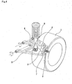
- FIG. 4 illustrates a first example of conventional construction of a double wishbone suspension that is disclosed in " Illustrated Book of Car Mechanisms and Structures" (Hosokawa, Takeshi; Grand Prix Book Publishing Co., Ltd.; January 10, 2003; pg. 207 ).
- the upper arm 4 is made using a so-called A-frame having an A shape, with the tip end section (when installed in the vehicle, the end section on the outside in the width direction of the vehicle, or the end section on the right side in FIG. 4 ) thereof being connected to the top end section of the knuckle 3 by way of an upper ball joint 6.
- the base end section of the upper arm 4 (when installed in the vehicle, the end section on the center side in the width direction of the vehicle, or the end section on the left side in FIG. 4 ) is supported by the vehicle (not illustrated in the figure) by a pivot shaft so as to be able to pivot.
- the lower arm 5 is also made using so-called A-frame having an A shape, with the tip end section thereof being connected to the bottom end section of the knuckle 3 by way of a lower ball joint 7.
- the base end section of the lower arm 5 is supported by the vehicle (not illustrated in the figure) by a pivot shaft so as to be able to pivot.
- the lower arm 5 supports the bottom end section of a shock absorber 8, the top end of which is fastened to the vehicle, by a pivot shaft so as to be able to pivot.
- the camber angle is preset to a specified angle.
- the camber angle that is preset in this way cannot be changed according to the traveling conditions of the vehicle.
- the turning movement of a vehicle occurs due to the difference in drive force on the left and right wheels and the like, however mainly occurs due to lateral force on the tires.
- This lateral force on the tires is generated by the driver operating the steering wheel and causing the toe angle (steering angle) of the front wheels to change by way of a steering gear, and causing a shift (slip angle) to occur between the traveling direction of the vehicle and the direction of the tires.
- This lateral force on the tires in addition to the toe angle, is known to be affected by the change in the camber angle.
- FIG. 5 illustrates the relationship between the lateral force on the tires and the slip angle when the camber angle, which was found by the inventors through simulation, was used as a parameter. As can be clearly seen in FIG.
- JP 10-264636 (A ) discloses a double wishbone suspension for a vehicle that is capable of changing the camber angle according to the traveling condition of the vehicle.
- FIG. 6 illustrates a second example of conventional construction as disclosed in this patent literature.
- hydraulic cylinders 9 and 10 which are capable of expanding and contracting, are provided in the middle section of the upper arm 4a and lower arm 5a and make it possible for the entire length of upper arm 4a and the lower arm 5a to change.
- a sensor detects the angle of sideslip of the wheel 1, and when it is recognized that the camber angle must be changed, a specified amount of hydraulic oil is supplied to the hydraulic cylinders 9 and 10 from a hydraulic pump that is located in the engine room by way of hydraulic piping and various valves. As a result, the entire lengths of the upper arm 4a and the lower arm 5a are changed and the camber angle of the wheel 1 is changed. With the suspension of this second example of convention construction, it is possible to adjust the size of the lateral force on the tires, and improve the turning performance of the vehicle, as well as the performance for traveling straight.
- JP 2009-107533 (A ) and JP 2010-83212 (A ) disclose camber angle adjustment apparatuses for changing the size of the camber angle according to the traveling conditions of the vehicle.
- JP 10-263636 (A ) there is a problem in that the construction for making it possible to change the camber angle is complex, and invites an increase in size and weight of the suspension.
- a load measurement apparatus for measure a load applied to a bearing unit that is disclosed in JP 2005-98771 (A ).
- JP 52 08 89 20 discloses also an adjustable track device.
- the object of the present invention is to achieve simple construction of suspension for a vehicle that is capable of suitably changing the camber angle according to the traveling condition of the vehicle without inviting complexity of the apparatus and also the increase in size and weight that accompanies such a complex apparatus.
- the suspension for a vehicle of the present invention basically is the same as a double wishbone suspension for a vehicle having conventional construction, and comprises: an upper arm that has a tip end section that is connected by way of an upper joint to the upper portion of a knuckle by which a wheel is supported so as to be able to rotate, and a base end section that is supported by the vehicle so as to be able to pivot in the up-down direction; and a lower arm that has a tip end section that is connected by way of a lower joint to the lower portion of the knuckle, and a base end section that is supported by the vehicle so as to be able to pivot in the up-down direction.
- the suspension for a vehicle of the present invention is characterized by the construction of the upper arm.
- the upper arm of the suspension for a vehicle of the present invention comprises:
- the suspension for an automobile of the present invention is characterized in that by the electric motor rotating and driving the worm so as to cause the pair of screw shafts to move out in opposite directions from each other in the axial direction, the opening angle of the pair of link arms changes, and thus the length of the pair of link arms in the width direction of the vehicle changes, or in other words, the overall length of the upper arm in the width direction of the vehicle changes.
- a feed screw mechanism By respectively combining the pair of screw shafts and the pair of screw nuts, a feed screw mechanism is formed.
- a sliding screw type feed screw mechanism can be applied as this feed screw mechanism, wherein the pair of screw shafts and the pair of screw nuts are respectively combined, and a female screw thread that is formed around the inner circumferential surface of each of the screw nuts engage with a male screw thread that is formed around the outer circumferential surface of each of the screw shafts such that they can slide against one another.
- a ball screw type feed screw mechanism can be applied as this feed screw mechanism, wherein the pair of screw shafts and the pair of screw nuts are respectively combined, and an outer-diameter side ball screw groove that is formed around the inner circumferential surface of each of the screw nuts engage with an inner-diameter side ball screw groove that is formed around the outer circumferential surface of each of the screw shafts by way of a plurality of balls that are placed between them.
- a rotation stopping mechanism for preventing relative rotation of the screw shafts with respect to the casing while allowing axial displacement of the screw shafts is provided between the pair of screw shafts and the casing.
- the worm wheel is made of synthetic resin. Furthermore, preferably, a speed reducer that increases the power of the electric motor and transmits that power to the worm is provided between the worm and the electric motor.
- the present invention constructed as described above, it is possible to achieve a suspension for a vehicle with simple construction that is capable of suitably changing the camber angle according to the traveling conditions of the vehicle, and it is possible to make the overall suspension more compact and lightweight.
- construction for making it possible to change the overall length of the upper arm is consolidated in the upper arm itself. Therefore, the other members, such as the lower arm, can be the same as used in the conventional construction.
- the upper arm is such that by using simple construction of just combining a pair of feed screw mechanisms, a worm reduction gear and a link mechanism, it becomes possible to change the overall length of the upper arm.
- control of the camber angle (control of the overall length of the upper arm) is performed controlling the supply of electricity to an electric motor, so when compared to being controlled hydraulically, there is excellent controllability and response, and there is little power loss of the engine.
- electric power energy is consumed only when the motor is being driven, so it is also possible to save energy. It is also possible to independently control the camber angle of the left and right wheels.
- FIG. 1 to FIG. 3 illustrate an example of an embodiment of the present invention.
- a feature of this example is making it possible to suitably change the camber angle ⁇ according to the traveling conditions of a vehicle by consolidating construction for making it possible to change the overall length of the upper arm 4b in the upper arm 4b itself of a double wishbone suspension of a vehicle.
- the lower arm 5 and other members are the same as in the first example of conventional construction illustrated in FIG. 4 . Therefore, the explanation below will center on the construction of the upper arm 4b, which is the feature of this example.
- the knuckle 3 which supports the wheel 1 by way of a bearing unit 2 so as to be able to rotate, is supported by the vehicle 11 (see FIG. 2 ) by way of the upper arm 4b and lower arm 5 so as to be able to pivot.
- the tip end section (right end section in FIG. 1 and FIG. 2 ) of the upper arm 4b is connected to the top end section of the knuckle 3 by way of an upper ball joint 6, which is an upper joint, and the base end section (left end section in FIG. 1 and FIG. 2 ) of the upper arm 4b is supported by the vehicle 11 so as to be able to pivot.
- the tip end section of the lower arm 5 is connected to the bottom end section of the knuckle 3 by way of a lower ball joint 7, which is a lower joint, and the base end section of the lower arm 5 is supported by the vehicle 11 so as to be able to pivot.
- a lower ball joint 7 which is a lower joint
- normally ball joints are used for these joints, however as long as pivotal displacement in each direction of the tip end sections of the upper arm 4b and lower arm 5 is allowed, it is possible to use other construction, including a Cardan joint.
- this upper arm 4b is constructed by a casing 12, a pair of feed screw mechanism 13a, 13b, a worm reduction gear 14, and a link mechanism 15.
- the casing 12 is supported by a pair of installation sections 16 that are provided on the vehicle 11 and separated in the forward-backward direction using bolts 17 and nuts 18 and by way of a rubber bushing so as to be able to pivot in the up-down direction of the vehicle 11, with the base end half (inner half in the width direction, left half section in FIG. 2 ) located in a portion between the installation sections 16.
- the center axis of both bolts 17 coincides with the center of pivoting of the upper arm 4b.
- the feed screw mechanisms 13a, 13b are located in the forward-backward direction of the vehicle 11 on the inside of the tip end half of the casing 12 (outer half in the width direction, right half in FIG. 2 ), and the worm reduction gear 14 is provided in the center section in the forward-backward direction of the base end half of the casing 12.
- Each feed screw mechanism 13a (13b) is a sliding screw type feed screw mechanism that is constructed by a combination of a screw shaft 20a (20b) and a screw nut 21a (21b).
- the screw shafts 20a, 20b are made of stainless steel for example, and are located on the same axis in the forward-backward direction of the vehicle 11.
- Helical shaped male screw threads are formed on the outer circumferential surface of the screw shafts 20a, 20b, and the pitch is the same between these screw shafts 20a, 20b.
- a rotation stopping convex section (not illustrated in the figures) is formed on at least part of the outer circumferential surface of each screw shaft 20a, 20b, and this rotation stopping convex section engages with a rotation stopping concave groove (not illustrated in the figures) that is formed on the casing 12.
- the screw shafts 20a, 20b are supported by the casing 12 wherein, with this rotation stopping mechanism, displacement in the axial direction with respect to the casing 12 is allowed, however, relative rotation is prevented.
- by using sliding screw type screw feed mechanisms it is possible to reduce the number of parts and make the suspension more lightweight.
- Both of the screw nuts 21a, 21b are made of a synthetic resin such as polyphenylene sulfide, polyamide-66, polyether ether ketone (PEEK), polyacetal or the like, and helical female screw threads are formed on the inner circumferential surfaces thereof.
- these screw nuts 21a, 21b are formed at the same time by injection molding such that the base end sections are integrated with each other.
- the female screw threads that are formed on the inner circumferential surfaces of these screw nuts 21a, 21b such that they are in the opposite direction from each other.
- the screw nuts 21a, 21b having this kind of construction are supported on the inside of the casing 12 so as to only be able to rotate, and the female threads that are formed on the inner circumferential surfaces thereof engage with the male threads that are formed in opposite directions from each other on the outer circumferential surface of the screw shafts 20a, 20b such that sliding movement is possible.
- the worm reduction gear 14, as illustrated in FIG. 3 is constructed by a worm wheel 22, a worm 23, an electric motor 24 and a speed reducer 25.
- the worm wheel 22 is made of a synthetic resin such as polyphenylene sulfide, polyamide-66, MC nylon (registered trademark), which is a kind of polyamide resin, polyether ether ketone (PEEK), polyacetal or the like, and is placed so as to be concentric with the screw nuts 21a, 21b. Glass fibers or carbon fibers are added to the synthetic resin, making it possible to improve the strength and rigidity of the worm wheel 22.
- the worm wheel 22 is directly formed around the outer circumferential surface of the center section in the axial direction of the screw nut 21a, 21b (portion that corresponds to the connecting section that connects the base end sections of the screw nuts 21a, 21b). Therefore, the worm wheel 22 rotates together with the screw nuts 21a, 21b.
- the worm wheel 22 By making the worm wheel 22 using synthetic resin in this way, it is possible to reduce the weight of the suspension, however, alternatively, it is also possible to form the worm wheel 22 separately, and connect and fasten the worm wheel 22 directly to the screw nuts 21a, 21b, or indirectly by way of another member. In this case, the freedom of selecting the material for the worm wheel 22 is improved.
- the worm 23 is made of metal or synthetic resin, and is constructed by a worm shaft 26 that is located in a twisted position with respect to the screw shafts 20a, 20b, and worm teeth 27 that are formed on the outer circumferential surface of the middle section of the worm shaft 26.
- the worm teeth 27 of the worm 23 engage with the worm wheel 22.
- the twist angle of the worm teeth 27 set to be large
- rotation of the worm wheel is not transmitted to the worm 23.
- the overall length of the upper arm 4b does not change when force is applied from the wheel to a pair of link arms 29a, 29b of the link mechanism 15.
- the electric motor itself by providing the electric motor itself with a brake function, it is possible to obtain the same effect.
- the electric motor 24 is supported by and fastened to the casing by a plurality of screws 28 (three screws in the example in the figures). By switching the power supply state, the electric motor 24 drives the drive shaft (not illustrated in the figure) in the forward or reverse direction.
- the speed reducer 25 is constructed by a plurality of gears (not illustrated in the figure) that increase the power (torque) of the electric motor 24, and this speed reducer 25 transmits that power to the worm shaft 26 of the worm 23.
- a speed reducer 25 it is possible to use an electric motor 24 that is more compact, and thus it is also possible to make the overall suspension for a vehicle compact and lightweight.
- the link mechanism 15 is constructed by a pair of link arms 29a, 29b and a connecting member 30.
- the pair of link arms 29a, 29b are casted parts made using an iron-based alloy, aluminum alloy, magnesium alloy or the like, and are formed into rod shapes that are slightly bent into arc shapes.
- the connecting member 30 is composed of a socket of the upper joint 6, and a cover 31 that covers the upper portion of the ball housing section is provided in the center section thereof.
- the base end sections of the link arms are connected to the tip end sections of the screw shafts 20a, 20b using a joint member 32a so as to be able to rotate around a shaft in the up-down direction of the vehicle (front-back direction in FIG. 2A, 2B ), and the tip end sections of the link arms 29a, 29b are connected to the corner sections of the connecting member 30 using a joint member 32b so as to be able to rotate around the shaft in the up-down direction of the vehicle 11.
- an encoder and load sensor (not illustrated in the figures) that are placed inside a bearing unit 2 that is conventionally known such as that disclosed in JP 2005-98771 (A ) are used to measure the lateral force on the tire (axial load) that is applied to the wheel 1.
- the data of the measured lateral force on the tire is sent to a controller (not illustrated in the figures), and by this controller using a comparison and judgment method, the controller determines whether the lateral force on the tire is excessive or insufficient for the current traveling condition of the vehicle. Then, based on that result, it performs control to supply electric power to the electric motor 24 (direction and amount).
- the electric motor 24 rotates and drives the worm 23 a specified number of revolutions (rotation angle) in the forward direction or reverse direction.
- the screw nuts 21a, 21b are rotated by way of the worm wheel 22, and the screw shafts 20a, 20b move apart a specified amount in different directions from each other in the axial direction (forward-backward direction of the vehicle, front-back direction in FIG. 1 , up-down direction in FIG. 2 ).
- the opening angle of the link arms 29a, 29b is changed, which changes the length L of the link arms 29a, 29b in the width direction of the vehicle (left-right direction in FIG. 1 and FIG. 2 ) by a specified amount (changes the overall length of the upper arm 4b).
- FIG. 2B exaggeratedly illustrates the amount that the screw shafts 20a, 20b protrude more than in the actual case. In the actual case, it is not necessary for the protruding amount to be as much as illustrated in FIG. 2B .
- the movable portion of each screw shaft is covered by a cover or bellows (not illustrated in the figures) in order to prevent foreign matter such as dirty water and the like from adhering the screw shafts.
- the upper arm 4b is such that by using simple construction of just combining a pair of feed screw mechanisms 13a, 13b, a worm reduction gear 14 and a link mechanism 15, it becomes possible to change the overall length of the upper arm 4b.
- a suspension for a vehicle that is able to suitably change the camber angle ⁇ according to the traveling conditions of the vehicle is achieved with simple construction, and it is possible to make that suspension more compact and lightweight.
- this kind of construction not only is it possible to improve the turning performance and the performance with traveling straight of the vehicle, but it is also possible to sufficiently suppress an increase in the unsprung weight, and to improve the traveling performance of the vehicle centered on traveling comfort and traveling stability.
- control of the camber angle ⁇ (control of the overall length of the upper arm 4b) is performed electrically, so when compared to being controlled hydraulically, there is excellent controllability and response, and there is little power loss of the engine. Furthermore, electric power (energy) is consumed only when being driven, so it is also possible to save energy.
- the overall length of the upper arm 4b is made to be able to change and not the lower arm 5, so even when the vehicle is stopped, it is possible to easily change the camber angle ⁇ .
- the suspension for a vehicle of the present invention to both the left and right wheels, it is possible to independently control the camber angle of the left and right wheels.
Landscapes
- Engineering & Computer Science (AREA)
- Mechanical Engineering (AREA)
- Vehicle Body Suspensions (AREA)
Description
- The present invention relates to a double wishbone suspension for a vehicle that can suitably change the camber angle according to the traveling condition of the vehicle.
- Various kinds of construction for a suspension for a vehicle such as an automobile are known. Recently, a double wishbone suspension, which has a high degree of design freedom and has excellent road surface followability, is used in many kinds of automobiles such as luxury automobiles and sports cars.
FIG. 4 illustrates a first example of conventional construction of a double wishbone suspension that is disclosed in "Illustrated Book of Car Mechanisms and Structures" (Hosokawa, Takeshi; Grand Prix Book Publishing Co., Ltd.; January 10, 2003; pg. 207). - A
knuckle 3, which supports awheel 1 by way of abearing unit 2 so as to be able to rotate, is supported by the vehicle (not illustrated in the figure) by anupper arm 4 and alower arm 5 of a double wishbone suspension so as to be able to pivot. Theupper arm 4 is made using a so-called A-frame having an A shape, with the tip end section (when installed in the vehicle, the end section on the outside in the width direction of the vehicle, or the end section on the right side inFIG. 4 ) thereof being connected to the top end section of theknuckle 3 by way of anupper ball joint 6. Moreover, the base end section of the upper arm 4 (when installed in the vehicle, the end section on the center side in the width direction of the vehicle, or the end section on the left side inFIG. 4 ) is supported by the vehicle (not illustrated in the figure) by a pivot shaft so as to be able to pivot. - On the other hand, the
lower arm 5 is also made using so-called A-frame having an A shape, with the tip end section thereof being connected to the bottom end section of theknuckle 3 by way of alower ball joint 7. Moreover, the base end section of thelower arm 5 is supported by the vehicle (not illustrated in the figure) by a pivot shaft so as to be able to pivot. Furthermore, thelower arm 5 supports the bottom end section of a shock absorber 8, the top end of which is fastened to the vehicle, by a pivot shaft so as to be able to pivot. - In the case of the double wishbone suspension having this kind of conventional construction, by using an
upper arm 4 andlower arm 5 having different overall lengths (typically the lower arm is longer than the upper arm), the camber angle is preset to a specified angle. However, in the case of a suspension having conventional construction, the camber angle that is preset in this way cannot be changed according to the traveling conditions of the vehicle. - Incidentally, the turning movement of a vehicle occurs due to the difference in drive force on the left and right wheels and the like, however mainly occurs due to lateral force on the tires. This lateral force on the tires is generated by the driver operating the steering wheel and causing the toe angle (steering angle) of the front wheels to change by way of a steering gear, and causing a shift (slip angle) to occur between the traveling direction of the vehicle and the direction of the tires. This lateral force on the tires, in addition to the toe angle, is known to be affected by the change in the camber angle.
FIG. 5 illustrates the relationship between the lateral force on the tires and the slip angle when the camber angle, which was found by the inventors through simulation, was used as a parameter. As can be clearly seen inFIG. 5 , even when the slip angle is constant, it is possible to cause the lateral force on the tires to change by causing the camber angle to change. Therefore, by being able to adjust the size of the lateral force on the tires by changing the camber angle, it is possible to improve the turning performance of the vehicle, as well as further improve the performance when going straight. -
JP 10-264636 (A FIG. 6 illustrates a second example of conventional construction as disclosed in this patent literature. In the case of this second example of conventional construction,hydraulic cylinders upper arm 4a andlower arm 5a and make it possible for the entire length ofupper arm 4a and thelower arm 5a to change. A sensor (not illustrated in the figure) detects the angle of sideslip of thewheel 1, and when it is recognized that the camber angle must be changed, a specified amount of hydraulic oil is supplied to thehydraulic cylinders upper arm 4a and thelower arm 5a are changed and the camber angle of thewheel 1 is changed. With the suspension of this second example of convention construction, it is possible to adjust the size of the lateral force on the tires, and improve the turning performance of the vehicle, as well as the performance for traveling straight. - However, in the case of this second example of conventional construction, in order to make it possible to change the camber angle, it is necessary to provide a hydraulic pump, hydraulic piping and various valves, and it is also necessary to provide
hydraulic cylinders upper arm 4a andlower arm 5a. Therefore, not only is there a problem in that the construction for making it possible to change the camber angle is complex, but there is also a problem in that the size and weight of the suspension are increased. Particularly, the increase in the weight of theupper arm 4a and thelower arm 5a is connected to an increase in the unsprung weight, which is undesirable from the aspect of improve traveling performance of the vehicle centered on comfort and traveling stability. Moreover, control of the camber angle is performed hydraulically, so there is a problem in that the controllability and response is bad, and furthermore there is a problem in that power loss of the engine becomes large. -
JP 2009-107533 (A JP 2010-83212 (A JP 10-263636 (A JP 2005-98771 (A -
JP 52 08 89 20 -
- [Patent Literature 1]
JP 10-264636 (A - [Patent Literature 2]
JP 2009-107533 (A - [Patent Literature 3]
JP 2010-83212 (A - [Patent Literature 4]
JP 2005-98771 (A - "Illustrated Book of Car Mechanisms and Structures", Hosokawa, Takeshi; Grand Prix Book Publishing Co., Ltd.; January 10, 2003; pg. 207
- In consideration of the situation described above, the object of the present invention is to achieve simple construction of suspension for a vehicle that is capable of suitably changing the camber angle according to the traveling condition of the vehicle without inviting complexity of the apparatus and also the increase in size and weight that accompanies such a complex apparatus.
- The suspension for a vehicle of the present invention, basically is the same as a double wishbone suspension for a vehicle having conventional construction, and comprises: an upper arm that has a tip end section that is connected by way of an upper joint to the upper portion of a knuckle by which a wheel is supported so as to be able to rotate, and a base end section that is supported by the vehicle so as to be able to pivot in the up-down direction; and a lower arm that has a tip end section that is connected by way of a lower joint to the lower portion of the knuckle, and a base end section that is supported by the vehicle so as to be able to pivot in the up-down direction.
- The suspension for a vehicle of the present invention is characterized by the construction of the upper arm. In other words, the upper arm of the suspension for a vehicle of the present invention comprises:
- a casing that is supported by the vehicle so as to be able to pivot in the up-down direction;
- a pair of screw shafts that are located on the same axis in the forward-backward direction of the vehicle, and are supported by the casing so as to be able to move only in the axial direction;
- a pair of screw nuts that engage around the pair of screw shafts, and are supported by the casing so as only to be able to rotate;
- a worm wheel that is combined with the pair of screw nuts so as to be able to rotate in synchronization with the screw nuts;
- a worm that comprises worm teeth that engage with the worm wheel;
- an electric motor that is supported by the casing, and is able to rotate and drive the worm in both directions; and
- a pair of link arms that have a tip end section and a base end section, where the base end sections respectively connect to the tip end sections of the pair of screw shafts so as to be able to rotate around a shaft in the up-down direction of the vehicle, and the tip end sections respectively connect to the upper joints so as to be able to rotate around a shaft in the up-down direction of the vehicle.
- Moreover, the suspension for an automobile of the present invention is characterized in that by the electric motor rotating and driving the worm so as to cause the pair of screw shafts to move out in opposite directions from each other in the axial direction, the opening angle of the pair of link arms changes, and thus the length of the pair of link arms in the width direction of the vehicle changes, or in other words, the overall length of the upper arm in the width direction of the vehicle changes.
- By respectively combining the pair of screw shafts and the pair of screw nuts, a feed screw mechanism is formed. A sliding screw type feed screw mechanism can be applied as this feed screw mechanism, wherein the pair of screw shafts and the pair of screw nuts are respectively combined, and a female screw thread that is formed around the inner circumferential surface of each of the screw nuts engage with a male screw thread that is formed around the outer circumferential surface of each of the screw shafts such that they can slide against one another.
- Alternatively, a ball screw type feed screw mechanism can be applied as this feed screw mechanism, wherein the pair of screw shafts and the pair of screw nuts are respectively combined, and an outer-diameter side ball screw groove that is formed around the inner circumferential surface of each of the screw nuts engage with an inner-diameter side ball screw groove that is formed around the outer circumferential surface of each of the screw shafts by way of a plurality of balls that are placed between them.
- Moreover, preferably, a rotation stopping mechanism for preventing relative rotation of the screw shafts with respect to the casing while allowing axial displacement of the screw shafts is provided between the pair of screw shafts and the casing.
- Preferably, the worm wheel is made of synthetic resin. Furthermore, preferably, a speed reducer that increases the power of the electric motor and transmits that power to the worm is provided between the worm and the electric motor.
- With the present invention constructed as described above, it is possible to achieve a suspension for a vehicle with simple construction that is capable of suitably changing the camber angle according to the traveling conditions of the vehicle, and it is possible to make the overall suspension more compact and lightweight. In other words, in the case of the suspension for a vehicle of the present invention, construction for making it possible to change the overall length of the upper arm (length of the link arms in the width direction of the vehicle) is consolidated in the upper arm itself. Therefore, the other members, such as the lower arm, can be the same as used in the conventional construction. Moreover, there is no need to install members such as a hydraulic pump on the vehicle side (for example, the engine room) as was required in the second example of conventional construction. Furthermore, the upper arm is such that by using simple construction of just combining a pair of feed screw mechanisms, a worm reduction gear and a link mechanism, it becomes possible to change the overall length of the upper arm.
- Therefore, with the suspension for a vehicle of the present invention, not only is it possible to improve the turning performance and the performance with traveling straight of the vehicle, but it is also possible to sufficiently suppress an increase in the unsprung weight, and to improve the traveling performance of the vehicle centered on traveling comfort and traveling stability. Furthermore, control of the camber angle (control of the overall length of the upper arm) is performed controlling the supply of electricity to an electric motor, so when compared to being controlled hydraulically, there is excellent controllability and response, and there is little power loss of the engine. In addition, electric power (energy) is consumed only when the motor is being driven, so it is also possible to save energy. It is also possible to independently control the camber angle of the left and right wheels.
-
-
FIG. 1 is a front view that schematically illustrates the suspended state of a wheel by a vehicle in the case of a first example of suspension for a vehicle of an embodiment of the present invention. -
FIGS. 2A and 2B are top views of an upper arm that has been removed from the suspension for a vehicle that is illustrated inFIG. 1 as seen from above the vehicle, whereFIG. 2A illustrates the maximum overall length, andFIG. 2B illustrates the minimum overall length. -
FIG. 3 is a drawing illustrated a worm reduction gear that has been removed from the suspension for a vehicle that is illustrated inFIG. 1 . -
FIG. 4 is a perspective view that schematically illustrates a first example of conventional construction of a suspension for a vehicle. -
FIG. 5 is a graph that illustrates the relationship between the lateral force on the tires and the slip angle when the camber angle, which was found through simulation, was used as a parameter. -
FIG. 6 is a front view that schematically illustrates a second example of conventional construction of a suspension for a vehicle. -
FIG. 1 to FIG. 3 illustrate an example of an embodiment of the present invention. A feature of this example is making it possible to suitably change the camber angle γ according to the traveling conditions of a vehicle by consolidating construction for making it possible to change the overall length of theupper arm 4b in theupper arm 4b itself of a double wishbone suspension of a vehicle. Thelower arm 5 and other members are the same as in the first example of conventional construction illustrated inFIG. 4 . Therefore, the explanation below will center on the construction of theupper arm 4b, which is the feature of this example. - As illustrated in
FIG. 1 , even in the case of the suspension for a vehicle of this example, theknuckle 3, which supports thewheel 1 by way of abearing unit 2 so as to be able to rotate, is supported by the vehicle 11 (seeFIG. 2 ) by way of theupper arm 4b andlower arm 5 so as to be able to pivot. In order for this, the tip end section (right end section inFIG. 1 andFIG. 2 ) of theupper arm 4b is connected to the top end section of theknuckle 3 by way of an upper ball joint 6, which is an upper joint, and the base end section (left end section inFIG. 1 andFIG. 2 ) of theupper arm 4b is supported by thevehicle 11 so as to be able to pivot. Moreover, the tip end section of thelower arm 5 is connected to the bottom end section of theknuckle 3 by way of a lower ball joint 7, which is a lower joint, and the base end section of thelower arm 5 is supported by thevehicle 11 so as to be able to pivot. Here, normally ball joints are used for these joints, however as long as pivotal displacement in each direction of the tip end sections of theupper arm 4b andlower arm 5 is allowed, it is possible to use other construction, including a Cardan joint. - Particularly in the case of this example, in order to make it possible to change the overall length of the
upper arm 4b, thisupper arm 4b is constructed by acasing 12, a pair offeed screw mechanism worm reduction gear 14, and alink mechanism 15. Thecasing 12 is supported by a pair ofinstallation sections 16 that are provided on thevehicle 11 and separated in the forward-backwarddirection using bolts 17 andnuts 18 and by way of a rubber bushing so as to be able to pivot in the up-down direction of thevehicle 11, with the base end half (inner half in the width direction, left half section inFIG. 2 ) located in a portion between theinstallation sections 16. In this example, the center axis of bothbolts 17 coincides with the center of pivoting of theupper arm 4b. Moreover, thefeed screw mechanisms vehicle 11 on the inside of the tip end half of the casing 12 (outer half in the width direction, right half inFIG. 2 ), and theworm reduction gear 14 is provided in the center section in the forward-backward direction of the base end half of thecasing 12. - Each
feed screw mechanism 13a (13b) is a sliding screw type feed screw mechanism that is constructed by a combination of ascrew shaft 20a (20b) and ascrew nut 21a (21b). Thescrew shafts vehicle 11. Helical shaped male screw threads are formed on the outer circumferential surface of thescrew shafts screw shafts screw shaft casing 12. Thescrew shafts casing 12 wherein, with this rotation stopping mechanism, displacement in the axial direction with respect to thecasing 12 is allowed, however, relative rotation is prevented. In this example, by using sliding screw type screw feed mechanisms, it is possible to reduce the number of parts and make the suspension more lightweight. However, alternatively, by using ball screw type feed screw mechanisms, it is possible to reduce the torque required for rotating and driving thescrew shafts screw shafts - Both of the screw nuts 21a, 21b are made of a synthetic resin such as polyphenylene sulfide, polyamide-66, polyether ether ketone (PEEK), polyacetal or the like, and helical female screw threads are formed on the inner circumferential surfaces thereof. In this example, these
screw nuts screw nuts screw nuts casing 12 so as to only be able to rotate, and the female threads that are formed on the inner circumferential surfaces thereof engage with the male threads that are formed in opposite directions from each other on the outer circumferential surface of thescrew shafts - The
worm reduction gear 14, as illustrated inFIG. 3 , is constructed by aworm wheel 22, aworm 23, anelectric motor 24 and aspeed reducer 25. Theworm wheel 22 is made of a synthetic resin such as polyphenylene sulfide, polyamide-66, MC nylon (registered trademark), which is a kind of polyamide resin, polyether ether ketone (PEEK), polyacetal or the like, and is placed so as to be concentric with the screw nuts 21a, 21b. Glass fibers or carbon fibers are added to the synthetic resin, making it possible to improve the strength and rigidity of theworm wheel 22. In this example, by processing and forming theworm wheel 22 at the same time as the screw nuts 21a, 21b by injection molding, theworm wheel 22 is directly formed around the outer circumferential surface of the center section in the axial direction of thescrew nut worm wheel 22 rotates together with the screw nuts 21a, 21b. By making theworm wheel 22 using synthetic resin in this way, it is possible to reduce the weight of the suspension, however, alternatively, it is also possible to form theworm wheel 22 separately, and connect and fasten theworm wheel 22 directly to the screw nuts 21a, 21b, or indirectly by way of another member. In this case, the freedom of selecting the material for theworm wheel 22 is improved. - The
worm 23 is made of metal or synthetic resin, and is constructed by aworm shaft 26 that is located in a twisted position with respect to thescrew shafts worm teeth 27 that are formed on the outer circumferential surface of the middle section of theworm shaft 26. Theworm teeth 27 of theworm 23 engage with theworm wheel 22. In this example, by regulating the twist angle of the worm teeth 27 (set to be large), rotation of the worm wheel is not transmitted to theworm 23. As a result, the overall length of theupper arm 4b does not change when force is applied from the wheel to a pair oflink arms link mechanism 15. Alternatively, by providing the electric motor itself with a brake function, it is possible to obtain the same effect. - The
electric motor 24 is supported by and fastened to the casing by a plurality of screws 28 (three screws in the example in the figures). By switching the power supply state, theelectric motor 24 drives the drive shaft (not illustrated in the figure) in the forward or reverse direction. Moreover, thespeed reducer 25 is constructed by a plurality of gears (not illustrated in the figure) that increase the power (torque) of theelectric motor 24, and thisspeed reducer 25 transmits that power to theworm shaft 26 of theworm 23. In this example, by providing aspeed reducer 25, it is possible to use anelectric motor 24 that is more compact, and thus it is also possible to make the overall suspension for a vehicle compact and lightweight. - The
link mechanism 15 is constructed by a pair oflink arms member 30. The pair oflink arms member 30 is composed of a socket of theupper joint 6, and acover 31 that covers the upper portion of the ball housing section is provided in the center section thereof. In this example, the base end sections of the link arms are connected to the tip end sections of thescrew shafts joint member 32a so as to be able to rotate around a shaft in the up-down direction of the vehicle (front-back direction inFIG. 2A, 2B ), and the tip end sections of thelink arms member 30 using ajoint member 32b so as to be able to rotate around the shaft in the up-down direction of thevehicle 11. - In this example, an encoder and load sensor (not illustrated in the figures) that are placed inside a
bearing unit 2 that is conventionally known such as that disclosed inJP 2005-98771 (A wheel 1. The data of the measured lateral force on the tire is sent to a controller (not illustrated in the figures), and by this controller using a comparison and judgment method, the controller determines whether the lateral force on the tire is excessive or insufficient for the current traveling condition of the vehicle. Then, based on that result, it performs control to supply electric power to the electric motor 24 (direction and amount). - More specifically, the
electric motor 24 rotates and drives the worm 23 a specified number of revolutions (rotation angle) in the forward direction or reverse direction. As a result, the screw nuts 21a, 21b are rotated by way of theworm wheel 22, and thescrew shafts FIG. 1 , up-down direction inFIG. 2 ). Then the opening angle of thelink arms link arms FIG. 1 andFIG. 2 ) by a specified amount (changes the overall length of theupper arm 4b). More specifically, when theelectric motor 24 is driven so that the amount that thescrew shafts casing 12 is small as illustrated inFIG. 2A , the opening angle of thelink arms link arms vehicle 11 becomes large (L = Lmax), and the overall length of theupper arm 4b becomes long. As a result, the distance from the center of pivoting O of theupper arm 4b to the center P of the upper ball joint 6 becomes large, and the camber angle γ changes. In other words, in the case of a positive camber, the camber angle becomes even larger, and in the case of a negative camber, the camber angle becomes smaller. On the other hand, when theelectric motor 24 is driven so that the amount that thescrew shafts casing 12 becomes large as illustrated inFIG. 2B , the opening angle of the link arms 28a, 28b becomes large. By doing so, the length of thelink arms vehicle 11 becomes small (L = Lmin), and the overall length of theupper arm 4b becomes short. As a result, the distance from the center of pivoting O of theupper arm 4b to the center P of the upper ball joint 6 becomes small, and the camber angle γ changes. In other words, in the case of a positive camber, the camber angle becomes smaller, and in the case of a negative camber, the camber angle becomes even larger. - The suspension for a vehicle of this example, by operating in this way, makes it possible to suitably change the camber angle γ according to the traveling conditions of the vehicle, and thus it is possible to adjust the size of the lateral force on the tire that occurs. In order to make the explanation more clear,
FIG. 2B exaggeratedly illustrates the amount that thescrew shafts FIG. 2B . Moreover, the movable portion of each screw shaft is covered by a cover or bellows (not illustrated in the figures) in order to prevent foreign matter such as dirty water and the like from adhering the screw shafts. - As described above, in the case of the suspension for a vehicle of this example, construction for making it possible to change the overall length of the
upper arm 4b is consolidated in theupper arm 4b itself, and does not require the installation of a member such as a hydraulic pump or the like on the vehicle side. Furthermore, theupper arm 4b is such that by using simple construction of just combining a pair offeed screw mechanisms worm reduction gear 14 and alink mechanism 15, it becomes possible to change the overall length of theupper arm 4b. In the present invention, with this kind of construction, a suspension for a vehicle that is able to suitably change the camber angle γ according to the traveling conditions of the vehicle is achieved with simple construction, and it is possible to make that suspension more compact and lightweight. With this kind of construction, not only is it possible to improve the turning performance and the performance with traveling straight of the vehicle, but it is also possible to sufficiently suppress an increase in the unsprung weight, and to improve the traveling performance of the vehicle centered on traveling comfort and traveling stability. - Moreover, in this example, control of the camber angle γ (control of the overall length of the
upper arm 4b) is performed electrically, so when compared to being controlled hydraulically, there is excellent controllability and response, and there is little power loss of the engine. Furthermore, electric power (energy) is consumed only when being driven, so it is also possible to save energy. - In addition, the overall length of the
upper arm 4b is made to be able to change and not thelower arm 5, so even when the vehicle is stopped, it is possible to easily change the camber angle γ. Furthermore, by applying the suspension for a vehicle of the present invention to both the left and right wheels, it is possible to independently control the camber angle of the left and right wheels. -
- 1
- Wheel
- 2
- Bearing unit
- 3
- Knuckle
- 4, 4a, 4b
- Upper arm
- 5, 5a
- Lower arm
- 6
- Upper ball joint
- 7
- Lower ball joint
- 8
- Shock absorber
- 9
- Hydraulic cylinder
- 10
- Hydraulic cylinder
- 11
- Vehicle
- 12
- Casing
- 13a, 13b
- Feed screw mechanism
- 14
- Worm reduction gear
- 15
- Link mechanism
- 16
- Installation section
- 17
- Bolt
- 18
- Nut
- 19
- Bushing
- 20a, 20b
- Screw shaft
- 21a, 21b
- Screw nut
- 22
- Worm wheel
- 23
- Worm
- 24
- Electric motor
- 25
- Speed reducer
- 26
- Worm shaft
- 27
- Worm teeth
- 28
- Screw
- 29a, 29b
- Link arm
- 30
- Connecting member
- 31
- Housing section
- 32a, 32b
- Joint member
Claims (6)
- A suspension for a vehicle comprising:an upper arm (4b) that has a tip end section that is connected by way of an upper joint to the upper portion of a knuckle (3) by which a wheel is supported so as to be able to rotate, and a base end section that is supported by the vehicle so as to be able to pivot in the up-down direction; anda lower arm (5) that has a tip end section that is connected by way of a lower joint to the lower portion of the knuckle (3), and a base end section that is supported by the vehicle so as to be able to pivot in the up-down direction; whereinthe upper arm comprises:a casing (12) that is supported by the vehicle so as to be able to pivot in the up-down direction;a pair of screw shafts (20) that are located on the same axis in the forward-backward direction of the vehicle, and are supported by the casing so as to be able to move only in the axial direction;a pair of screw nuts (21) that engage around the pair of screw shafts (20), and are supported by the casing (12) so as only to be able to rotate;a worm wheel (22) that is combined with the pair of screw nuts so as to be able to rotate in synchronization with the screw nuts (21);a worm that comprises worm teeth that engage with the worm wheel;an electric motor (24) that is supported by the casing, and is able to rotate and drive the worm in both directions; anda pair of link arms (29) that have a tip end section and a base end section, where the base end sections respectively connect to the tip end sections of the pair of screw shafts (20) so as to be able to rotate around a shaft in the up-down direction of the vehicle, and the tip end sections respectively connect to the upper joints so as to be able to rotate around a shaft in the up-down direction of the vehicle, and whereinby the electric motor (24) rotating and driving the worm (22) so as to cause the pair of screw shafts (20) to move out in opposite directions from each other in the axial direction, the opening angle of the pair of link arms (29) changes, and thus the length of the pair of link arms in the width direction of the vehicle changes.
- The suspension for a vehicle according to claim 1, wherein the combination of the pair of screw shafts and the pair of screw nuts is constructed by a sliding screw type feed screw mechanism where a female screw thread that is formed around the inner circumferential surface each of the screw nuts engage with a male screw thread that is formed around the outer circumferential surface each of the screw shafts such that they can slide against one another.
- The suspension for a vehicle according to claim 1, wherein the combination of the pair of screw shafts and the pair of screw nuts is constructed by a ball screw type feed screw mechanism where an outer-diameter side ball screw groove that is formed around the inner circumferential surface of each of the screw nuts engage with an inner-diameter side ball screw groove that is formed around the outer circumferential surface of each of the screw shafts by way of a plurality of balls that are placed between the outer-diameter side ball screw groove and the inner-diameter side ball screw groove.
- The suspension for a vehicle according to any one of the claims 1 to 3, wherein a rotation stopping mechanism for preventing relative rotation of the screw shafts with respect to the casing while allowing axial displacement of the screw shafts is provided between the pair of screw shafts and the casing.
- The suspension for a vehicle according to any one of the claims 1 to 4, wherein the worm wheel is made of synthetic resin.
- The suspension for an automobile according to any one of the claims 1 to 5, wherein a speed reducer that increases the power of the electric motor and transmits that power to the worm is provided between the worm and the electric motor.
Applications Claiming Priority (2)
| Application Number | Priority Date | Filing Date | Title |
|---|---|---|---|
| JP2011109757 | 2011-05-16 | ||
| PCT/JP2012/054976 WO2013051298A1 (en) | 2011-05-16 | 2012-02-28 | Suspension device for vehicle |
Publications (3)
| Publication Number | Publication Date |
|---|---|
| EP2711212A1 EP2711212A1 (en) | 2014-03-26 |
| EP2711212A4 EP2711212A4 (en) | 2014-10-29 |
| EP2711212B1 true EP2711212B1 (en) | 2015-11-25 |
Family
ID=47526771
Family Applications (1)
| Application Number | Title | Priority Date | Filing Date |
|---|---|---|---|
| EP12838999.6A Not-in-force EP2711212B1 (en) | 2011-05-16 | 2012-02-28 | Suspension device for vehicle |
Country Status (5)
| Country | Link |
|---|---|
| US (1) | US8944439B2 (en) |
| EP (1) | EP2711212B1 (en) |
| JP (1) | JP6035852B2 (en) |
| CN (1) | CN103534109B (en) |
| WO (1) | WO2013051298A1 (en) |
Families Citing this family (10)
| Publication number | Priority date | Publication date | Assignee | Title |
|---|---|---|---|---|
| JP5910344B2 (en) * | 2012-06-20 | 2016-04-27 | 日本精工株式会社 | Vehicle suspension system |
| FR3013668B1 (en) * | 2013-11-22 | 2015-12-18 | Michel Raes | AUTOMATIC BODY ANGLE ADJUSTMENT DEVICE FOR A GROUND BONDING SYSTEM |
| ITTO20130969A1 (en) * | 2013-11-28 | 2015-05-29 | Zona Engineering & Design Sas Di Zo Na Mauro & C | SELF-MULTI-SUSPENSION SUSPENSION WITH VARIATION OF THE WINDING ANGLE |
| ITUB20153223A1 (en) * | 2015-08-25 | 2017-02-25 | Zona Eng & Design S A S Di Zona Mauro & C | Motor vehicle suspension with camber angle variation device |
| JPWO2017098814A1 (en) * | 2015-12-10 | 2018-09-27 | 日本精工株式会社 | Vehicle weight measuring device |
| US10633021B2 (en) | 2017-04-03 | 2020-04-28 | Robby Gordon | Modular chassis |
| CN108674109B (en) * | 2018-06-07 | 2020-02-18 | 东风(武汉)实业有限公司 | High-strength multifunctional triangular arm assembly |
| EP3587150B1 (en) * | 2018-06-08 | 2022-11-23 | Mando Corporation | Vehicle control apparatus and vehicle control method |
| JP7182455B2 (en) * | 2018-12-20 | 2022-12-02 | Ntn株式会社 | HUB UNIT WITH STEERING FUNCTION AND VEHICLE INCLUDING THE SAME |
| GB201904585D0 (en) * | 2019-04-02 | 2019-05-15 | R53 Engineering Ltd | Length adjustment device |
Family Cites Families (25)
| Publication number | Priority date | Publication date | Assignee | Title |
|---|---|---|---|---|
| JPS5288920A (en) * | 1976-01-17 | 1977-07-26 | Kubota Ltd | Apparatus for tread adjustment for tractor or the like |
| JPS61124766A (en) * | 1984-11-20 | 1986-06-12 | Copal Denshi Kk | Straight feeding mechanism for linear step actuator |
| JPH0450010A (en) * | 1990-06-18 | 1992-02-19 | Mitsubishi Motors Corp | Variable-length arm suspension device |
| JP2848191B2 (en) * | 1993-06-16 | 1999-01-20 | 三菱自動車エンジニアリング株式会社 | Actuator structure of vehicle suspension device |
| JP2898899B2 (en) * | 1995-02-14 | 1999-06-02 | 株式会社ナブコ | Motor-driven hydraulic actuator |
| JPH09507816A (en) * | 1995-05-22 | 1997-08-12 | ヒュンダイ モーター カンパニー | Steering wheel suspension system for wheels |
| JP3834920B2 (en) | 1997-03-26 | 2006-10-18 | 株式会社デンソー | Vehicle camber angle control device |
| AU738852C (en) * | 1997-12-12 | 2003-04-10 | Holland Neway International, Inc. | Independent front suspension |
| FR2844245B1 (en) * | 2002-09-10 | 2005-04-29 | Jean Marie Obry | UNIVERSAL VEHICLE FOR ROAD TRANSPORT, WANDAGE AND GROUND GUARD VARIABLES |
| JP2004108455A (en) * | 2002-09-17 | 2004-04-08 | Nsk Ltd | Ball screw device |
| US20050017471A1 (en) * | 2003-06-09 | 2005-01-27 | Matthew Kim | Steering with triple linkage suspension having steering adjusted camber |
| JP2005098771A (en) | 2003-09-24 | 2005-04-14 | Nsk Ltd | Load-measuring device of rolling bearing unit |
| JP4074273B2 (en) * | 2004-08-06 | 2008-04-09 | 治 三宅 | Handicap adjustment system |
| DE102005039318A1 (en) * | 2005-08-19 | 2007-02-22 | Audi Ag | Arrangement for adjusting length of suspension link at vehicle, comprises Watt linkage coupled with link divided into two parts |
| JP4956010B2 (en) * | 2006-02-03 | 2012-06-20 | 株式会社キャロッセ | Vehicle height adjustment control device for vehicle height adjustable suspension |
| JP2007253863A (en) * | 2006-03-24 | 2007-10-04 | Honda Motor Co Ltd | Vehicle height adjusting system |
| US7922181B2 (en) | 2006-03-09 | 2011-04-12 | Honda Motor Co., Ltd. | Vehicle height adjusting system |
| JP2008067555A (en) * | 2006-09-08 | 2008-03-21 | Minebea Co Ltd | Rotor assembly and manufacturing method therefor |
| JP2008105599A (en) * | 2006-10-26 | 2008-05-08 | Nissan Motor Co Ltd | Suspension device, automobile and vehicle motion control method |
| JP4848994B2 (en) * | 2006-12-22 | 2011-12-28 | 株式会社エクォス・リサーチ | Vehicle control device |
| JP2008184147A (en) | 2007-01-31 | 2008-08-14 | Aisin Seiki Co Ltd | Alignment control device |
| JP4993110B2 (en) | 2007-10-31 | 2012-08-08 | 株式会社エクォス・リサーチ | Camber angle adjustment mechanism |
| JP2009236281A (en) * | 2008-03-28 | 2009-10-15 | Honda Motor Co Ltd | Feed screw mechanism and rear wheel toe angle variable control device for vehicle using the same |
| JP5439784B2 (en) | 2008-09-29 | 2014-03-12 | 株式会社エクォス・リサーチ | Vehicle control device |
| KR101263674B1 (en) * | 2011-08-25 | 2013-05-22 | 대동공업주식회사 | Suspension constructure of Utility vehicle |
-
2012
- 2012-02-28 CN CN201280023448.4A patent/CN103534109B/en not_active Expired - Fee Related
- 2012-02-28 WO PCT/JP2012/054976 patent/WO2013051298A1/en active Application Filing
- 2012-02-28 US US14/117,703 patent/US8944439B2/en active Active
- 2012-02-28 EP EP12838999.6A patent/EP2711212B1/en not_active Not-in-force
- 2012-05-09 JP JP2012107531A patent/JP6035852B2/en not_active Expired - Fee Related
Also Published As
| Publication number | Publication date |
|---|---|
| EP2711212A1 (en) | 2014-03-26 |
| JP6035852B2 (en) | 2016-11-30 |
| CN103534109B (en) | 2016-04-13 |
| JP2012254784A (en) | 2012-12-27 |
| CN103534109A (en) | 2014-01-22 |
| US8944439B2 (en) | 2015-02-03 |
| US20140091538A1 (en) | 2014-04-03 |
| EP2711212A4 (en) | 2014-10-29 |
| WO2013051298A1 (en) | 2013-04-11 |
Similar Documents
| Publication | Publication Date | Title |
|---|---|---|
| EP2711212B1 (en) | Suspension device for vehicle | |
| US8753032B2 (en) | Friction controlled ball joint | |
| JP6909071B2 (en) | Hub unit with auxiliary steering function and vehicle | |
| JP7244994B2 (en) | Hub unit with steering function, steering system, and vehicle equipped with hub unit with steering function | |
| KR20080002924A (en) | Steering device, in particular for a rear axle steering system | |
| CN111094114B (en) | Wheel hub unit with auxiliary steering function and vehicle with same | |
| CN103625238A (en) | Electrically-controlled rigidity-adjustable initiative laterally stabilizing device | |
| JP6899465B2 (en) | Hub bearing with steering shaft and vehicle equipped with it | |
| JP6982416B2 (en) | Hub unit with auxiliary steering function and vehicle | |
| CN205930105U (en) | Automobile body height regulating mechanism and have its vehicle | |
| WO2020166537A1 (en) | Hub unit having steering function, and vehicle equipped with same | |
| JP2020097280A (en) | Hub unit with steering function and steering system | |
| JP6990078B2 (en) | Hub unit with steering function and vehicles equipped with it | |
| JP6982417B2 (en) | Hub unit with auxiliary steering function and vehicle | |
| WO2021182312A1 (en) | Hub unit having steering function, and vehicle equipped with same | |
| JP7177681B2 (en) | HUB UNIT WITH STEERING FUNCTION AND VEHICLE INCLUDING THE SAME | |
| JP5724808B2 (en) | Camber angle adjustment device | |
| JP2020097964A (en) | Linear motion mechanism, hub unit with steering mechanism and vehicle having the same | |
| US20210309285A1 (en) | Hub unit having steering function and vehicle provided with hub unit | |
| JP5910344B2 (en) | Vehicle suspension system | |
| WO2020250905A1 (en) | Steering device | |
| JP6899464B2 (en) | Hub bearing with steering shaft and vehicle equipped with it | |
| JP2020138691A (en) | Hub unit with steering function and vehicle having the same | |
| JP2024035555A (en) | Hub unit with steering function, steering system and vehicle | |
| JP2023047456A (en) | Hub unit with steering function, steering system, and vehicle |
Legal Events
| Date | Code | Title | Description |
|---|---|---|---|
| PUAI | Public reference made under article 153(3) epc to a published international application that has entered the european phase |
Free format text: ORIGINAL CODE: 0009012 |
|
| 17P | Request for examination filed |
Effective date: 20131111 |
|
| AK | Designated contracting states |
Kind code of ref document: A1 Designated state(s): AL AT BE BG CH CY CZ DE DK EE ES FI FR GB GR HR HU IE IS IT LI LT LU LV MC MK MT NL NO PL PT RO RS SE SI SK SM TR |
|
| DAX | Request for extension of the european patent (deleted) | ||
| A4 | Supplementary search report drawn up and despatched |
Effective date: 20140929 |
|
| RIC1 | Information provided on ipc code assigned before grant |
Ipc: B60G 7/00 20060101AFI20140923BHEP Ipc: B60G 17/016 20060101ALI20140923BHEP Ipc: B60G 17/015 20060101ALI20140923BHEP |
|
| GRAP | Despatch of communication of intention to grant a patent |
Free format text: ORIGINAL CODE: EPIDOSNIGR1 |
|
| INTG | Intention to grant announced |
Effective date: 20150703 |
|
| GRAS | Grant fee paid |
Free format text: ORIGINAL CODE: EPIDOSNIGR3 |
|
| GRAA | (expected) grant |
Free format text: ORIGINAL CODE: 0009210 |
|
| AK | Designated contracting states |
Kind code of ref document: B1 Designated state(s): AL AT BE BG CH CY CZ DE DK EE ES FI FR GB GR HR HU IE IS IT LI LT LU LV MC MK MT NL NO PL PT RO RS SE SI SK SM TR |
|
| REG | Reference to a national code |
Ref country code: GB Ref legal event code: FG4D |
|
| REG | Reference to a national code |
Ref country code: CH Ref legal event code: EP |
|
| REG | Reference to a national code |
Ref country code: AT Ref legal event code: REF Ref document number: 762396 Country of ref document: AT Kind code of ref document: T Effective date: 20151215 |
|
| REG | Reference to a national code |
Ref country code: IE Ref legal event code: FG4D |
|
| REG | Reference to a national code |
Ref country code: DE Ref legal event code: R096 Ref document number: 602012012790 Country of ref document: DE |
|
| REG | Reference to a national code |
Ref country code: LT Ref legal event code: MG4D |
|
| REG | Reference to a national code |
Ref country code: NL Ref legal event code: MP Effective date: 20160225 |
|
| REG | Reference to a national code |
Ref country code: AT Ref legal event code: MK05 Ref document number: 762396 Country of ref document: AT Kind code of ref document: T Effective date: 20151125 |
|
| PG25 | Lapsed in a contracting state [announced via postgrant information from national office to epo] |
Ref country code: NO Free format text: LAPSE BECAUSE OF FAILURE TO SUBMIT A TRANSLATION OF THE DESCRIPTION OR TO PAY THE FEE WITHIN THE PRESCRIBED TIME-LIMIT Effective date: 20160225 Ref country code: IS Free format text: LAPSE BECAUSE OF FAILURE TO SUBMIT A TRANSLATION OF THE DESCRIPTION OR TO PAY THE FEE WITHIN THE PRESCRIBED TIME-LIMIT Effective date: 20160325 Ref country code: LT Free format text: LAPSE BECAUSE OF FAILURE TO SUBMIT A TRANSLATION OF THE DESCRIPTION OR TO PAY THE FEE WITHIN THE PRESCRIBED TIME-LIMIT Effective date: 20151125 Ref country code: ES Free format text: LAPSE BECAUSE OF FAILURE TO SUBMIT A TRANSLATION OF THE DESCRIPTION OR TO PAY THE FEE WITHIN THE PRESCRIBED TIME-LIMIT Effective date: 20151125 Ref country code: HR Free format text: LAPSE BECAUSE OF FAILURE TO SUBMIT A TRANSLATION OF THE DESCRIPTION OR TO PAY THE FEE WITHIN THE PRESCRIBED TIME-LIMIT Effective date: 20151125 Ref country code: NL Free format text: LAPSE BECAUSE OF FAILURE TO SUBMIT A TRANSLATION OF THE DESCRIPTION OR TO PAY THE FEE WITHIN THE PRESCRIBED TIME-LIMIT Effective date: 20151125 |
|
| PG25 | Lapsed in a contracting state [announced via postgrant information from national office to epo] |
Ref country code: RS Free format text: LAPSE BECAUSE OF FAILURE TO SUBMIT A TRANSLATION OF THE DESCRIPTION OR TO PAY THE FEE WITHIN THE PRESCRIBED TIME-LIMIT Effective date: 20151125 Ref country code: FI Free format text: LAPSE BECAUSE OF FAILURE TO SUBMIT A TRANSLATION OF THE DESCRIPTION OR TO PAY THE FEE WITHIN THE PRESCRIBED TIME-LIMIT Effective date: 20151125 Ref country code: LV Free format text: LAPSE BECAUSE OF FAILURE TO SUBMIT A TRANSLATION OF THE DESCRIPTION OR TO PAY THE FEE WITHIN THE PRESCRIBED TIME-LIMIT Effective date: 20151125 Ref country code: PT Free format text: LAPSE BECAUSE OF FAILURE TO SUBMIT A TRANSLATION OF THE DESCRIPTION OR TO PAY THE FEE WITHIN THE PRESCRIBED TIME-LIMIT Effective date: 20160325 Ref country code: PL Free format text: LAPSE BECAUSE OF FAILURE TO SUBMIT A TRANSLATION OF THE DESCRIPTION OR TO PAY THE FEE WITHIN THE PRESCRIBED TIME-LIMIT Effective date: 20151125 Ref country code: SE Free format text: LAPSE BECAUSE OF FAILURE TO SUBMIT A TRANSLATION OF THE DESCRIPTION OR TO PAY THE FEE WITHIN THE PRESCRIBED TIME-LIMIT Effective date: 20151125 Ref country code: GR Free format text: LAPSE BECAUSE OF FAILURE TO SUBMIT A TRANSLATION OF THE DESCRIPTION OR TO PAY THE FEE WITHIN THE PRESCRIBED TIME-LIMIT Effective date: 20160226 Ref country code: AT Free format text: LAPSE BECAUSE OF FAILURE TO SUBMIT A TRANSLATION OF THE DESCRIPTION OR TO PAY THE FEE WITHIN THE PRESCRIBED TIME-LIMIT Effective date: 20151125 Ref country code: BE Free format text: LAPSE BECAUSE OF NON-PAYMENT OF DUE FEES Effective date: 20160229 |
|
| PG25 | Lapsed in a contracting state [announced via postgrant information from national office to epo] |
Ref country code: CZ Free format text: LAPSE BECAUSE OF FAILURE TO SUBMIT A TRANSLATION OF THE DESCRIPTION OR TO PAY THE FEE WITHIN THE PRESCRIBED TIME-LIMIT Effective date: 20151125 Ref country code: IT Free format text: LAPSE BECAUSE OF FAILURE TO SUBMIT A TRANSLATION OF THE DESCRIPTION OR TO PAY THE FEE WITHIN THE PRESCRIBED TIME-LIMIT Effective date: 20151125 |
|
| REG | Reference to a national code |
Ref country code: DE Ref legal event code: R097 Ref document number: 602012012790 Country of ref document: DE |
|
| PG25 | Lapsed in a contracting state [announced via postgrant information from national office to epo] |
Ref country code: SM Free format text: LAPSE BECAUSE OF FAILURE TO SUBMIT A TRANSLATION OF THE DESCRIPTION OR TO PAY THE FEE WITHIN THE PRESCRIBED TIME-LIMIT Effective date: 20151125 Ref country code: EE Free format text: LAPSE BECAUSE OF FAILURE TO SUBMIT A TRANSLATION OF THE DESCRIPTION OR TO PAY THE FEE WITHIN THE PRESCRIBED TIME-LIMIT Effective date: 20151125 Ref country code: RO Free format text: LAPSE BECAUSE OF FAILURE TO SUBMIT A TRANSLATION OF THE DESCRIPTION OR TO PAY THE FEE WITHIN THE PRESCRIBED TIME-LIMIT Effective date: 20151125 Ref country code: SK Free format text: LAPSE BECAUSE OF FAILURE TO SUBMIT A TRANSLATION OF THE DESCRIPTION OR TO PAY THE FEE WITHIN THE PRESCRIBED TIME-LIMIT Effective date: 20151125 Ref country code: DK Free format text: LAPSE BECAUSE OF FAILURE TO SUBMIT A TRANSLATION OF THE DESCRIPTION OR TO PAY THE FEE WITHIN THE PRESCRIBED TIME-LIMIT Effective date: 20151125 |
|
| PG25 | Lapsed in a contracting state [announced via postgrant information from national office to epo] |
Ref country code: MC Free format text: LAPSE BECAUSE OF FAILURE TO SUBMIT A TRANSLATION OF THE DESCRIPTION OR TO PAY THE FEE WITHIN THE PRESCRIBED TIME-LIMIT Effective date: 20151125 Ref country code: LU Free format text: LAPSE BECAUSE OF FAILURE TO SUBMIT A TRANSLATION OF THE DESCRIPTION OR TO PAY THE FEE WITHIN THE PRESCRIBED TIME-LIMIT Effective date: 20160228 |
|
| PLBE | No opposition filed within time limit |
Free format text: ORIGINAL CODE: 0009261 |
|
| REG | Reference to a national code |
Ref country code: CH Ref legal event code: PL |
|
| STAA | Information on the status of an ep patent application or granted ep patent |
Free format text: STATUS: NO OPPOSITION FILED WITHIN TIME LIMIT |
|
| GBPC | Gb: european patent ceased through non-payment of renewal fee |
Effective date: 20160228 |
|
| PG25 | Lapsed in a contracting state [announced via postgrant information from national office to epo] |
Ref country code: CH Free format text: LAPSE BECAUSE OF NON-PAYMENT OF DUE FEES Effective date: 20160229 Ref country code: LI Free format text: LAPSE BECAUSE OF NON-PAYMENT OF DUE FEES Effective date: 20160229 |
|
| 26N | No opposition filed |
Effective date: 20160826 |
|
| REG | Reference to a national code |
Ref country code: FR Ref legal event code: ST Effective date: 20161028 |
|
| PG25 | Lapsed in a contracting state [announced via postgrant information from national office to epo] |
Ref country code: SI Free format text: LAPSE BECAUSE OF FAILURE TO SUBMIT A TRANSLATION OF THE DESCRIPTION OR TO PAY THE FEE WITHIN THE PRESCRIBED TIME-LIMIT Effective date: 20151125 |
|
| REG | Reference to a national code |
Ref country code: IE Ref legal event code: MM4A |
|
| PG25 | Lapsed in a contracting state [announced via postgrant information from national office to epo] |
Ref country code: BE Free format text: LAPSE BECAUSE OF FAILURE TO SUBMIT A TRANSLATION OF THE DESCRIPTION OR TO PAY THE FEE WITHIN THE PRESCRIBED TIME-LIMIT Effective date: 20151125 |
|
| PG25 | Lapsed in a contracting state [announced via postgrant information from national office to epo] |
Ref country code: GB Free format text: LAPSE BECAUSE OF NON-PAYMENT OF DUE FEES Effective date: 20160228 Ref country code: FR Free format text: LAPSE BECAUSE OF NON-PAYMENT OF DUE FEES Effective date: 20160229 Ref country code: IE Free format text: LAPSE BECAUSE OF NON-PAYMENT OF DUE FEES Effective date: 20160228 |
|
| PG25 | Lapsed in a contracting state [announced via postgrant information from national office to epo] |
Ref country code: MT Free format text: LAPSE BECAUSE OF FAILURE TO SUBMIT A TRANSLATION OF THE DESCRIPTION OR TO PAY THE FEE WITHIN THE PRESCRIBED TIME-LIMIT Effective date: 20151125 |
|
| PG25 | Lapsed in a contracting state [announced via postgrant information from national office to epo] |
Ref country code: CY Free format text: LAPSE BECAUSE OF FAILURE TO SUBMIT A TRANSLATION OF THE DESCRIPTION OR TO PAY THE FEE WITHIN THE PRESCRIBED TIME-LIMIT Effective date: 20151125 Ref country code: HU Free format text: LAPSE BECAUSE OF FAILURE TO SUBMIT A TRANSLATION OF THE DESCRIPTION OR TO PAY THE FEE WITHIN THE PRESCRIBED TIME-LIMIT; INVALID AB INITIO Effective date: 20120228 |
|
| PG25 | Lapsed in a contracting state [announced via postgrant information from national office to epo] |
Ref country code: MT Free format text: LAPSE BECAUSE OF FAILURE TO SUBMIT A TRANSLATION OF THE DESCRIPTION OR TO PAY THE FEE WITHIN THE PRESCRIBED TIME-LIMIT Effective date: 20160229 Ref country code: TR Free format text: LAPSE BECAUSE OF FAILURE TO SUBMIT A TRANSLATION OF THE DESCRIPTION OR TO PAY THE FEE WITHIN THE PRESCRIBED TIME-LIMIT Effective date: 20151125 Ref country code: MK Free format text: LAPSE BECAUSE OF FAILURE TO SUBMIT A TRANSLATION OF THE DESCRIPTION OR TO PAY THE FEE WITHIN THE PRESCRIBED TIME-LIMIT Effective date: 20151125 |
|
| PG25 | Lapsed in a contracting state [announced via postgrant information from national office to epo] |
Ref country code: BG Free format text: LAPSE BECAUSE OF FAILURE TO SUBMIT A TRANSLATION OF THE DESCRIPTION OR TO PAY THE FEE WITHIN THE PRESCRIBED TIME-LIMIT Effective date: 20151125 |
|
| PG25 | Lapsed in a contracting state [announced via postgrant information from national office to epo] |
Ref country code: AL Free format text: LAPSE BECAUSE OF FAILURE TO SUBMIT A TRANSLATION OF THE DESCRIPTION OR TO PAY THE FEE WITHIN THE PRESCRIBED TIME-LIMIT Effective date: 20151125 |
|
| PGFP | Annual fee paid to national office [announced via postgrant information from national office to epo] |
Ref country code: DE Payment date: 20200218 Year of fee payment: 9 |
|
| REG | Reference to a national code |
Ref country code: DE Ref legal event code: R119 Ref document number: 602012012790 Country of ref document: DE |
|
| PG25 | Lapsed in a contracting state [announced via postgrant information from national office to epo] |
Ref country code: DE Free format text: LAPSE BECAUSE OF NON-PAYMENT OF DUE FEES Effective date: 20210901 |