EP2709781B1 - Système et procédé pour injecter de l'aluminium semi-solide dans un moule - Google Patents
Système et procédé pour injecter de l'aluminium semi-solide dans un moule Download PDFInfo
- Publication number
- EP2709781B1 EP2709781B1 EP12731688.3A EP12731688A EP2709781B1 EP 2709781 B1 EP2709781 B1 EP 2709781B1 EP 12731688 A EP12731688 A EP 12731688A EP 2709781 B1 EP2709781 B1 EP 2709781B1
- Authority
- EP
- European Patent Office
- Prior art keywords
- metal
- injection chamber
- mould
- temperature
- injection
- Prior art date
- Legal status (The legal status is an assumption and is not a legal conclusion. Google has not performed a legal analysis and makes no representation as to the accuracy of the status listed.)
- Active
Links
Images


Classifications
-
- B—PERFORMING OPERATIONS; TRANSPORTING
- B22—CASTING; POWDER METALLURGY
- B22D—CASTING OF METALS; CASTING OF OTHER SUBSTANCES BY THE SAME PROCESSES OR DEVICES
- B22D17/00—Pressure die casting or injection die casting, i.e. casting in which the metal is forced into a mould under high pressure
- B22D17/007—Semi-solid pressure die casting
-
- B—PERFORMING OPERATIONS; TRANSPORTING
- B22—CASTING; POWDER METALLURGY
- B22D—CASTING OF METALS; CASTING OF OTHER SUBSTANCES BY THE SAME PROCESSES OR DEVICES
- B22D17/00—Pressure die casting or injection die casting, i.e. casting in which the metal is forced into a mould under high pressure
- B22D17/08—Cold chamber machines, i.e. with unheated press chamber into which molten metal is ladled
- B22D17/12—Cold chamber machines, i.e. with unheated press chamber into which molten metal is ladled with vertical press motion
-
- B—PERFORMING OPERATIONS; TRANSPORTING
- B22—CASTING; POWDER METALLURGY
- B22D—CASTING OF METALS; CASTING OF OTHER SUBSTANCES BY THE SAME PROCESSES OR DEVICES
- B22D17/00—Pressure die casting or injection die casting, i.e. casting in which the metal is forced into a mould under high pressure
- B22D17/20—Accessories: Details
- B22D17/2015—Means for forcing the molten metal into the die
-
- B—PERFORMING OPERATIONS; TRANSPORTING
- B22—CASTING; POWDER METALLURGY
- B22D—CASTING OF METALS; CASTING OF OTHER SUBSTANCES BY THE SAME PROCESSES OR DEVICES
- B22D17/00—Pressure die casting or injection die casting, i.e. casting in which the metal is forced into a mould under high pressure
- B22D17/20—Accessories: Details
- B22D17/30—Accessories for supplying molten metal, e.g. in rations
-
- B—PERFORMING OPERATIONS; TRANSPORTING
- B22—CASTING; POWDER METALLURGY
- B22D—CASTING OF METALS; CASTING OF OTHER SUBSTANCES BY THE SAME PROCESSES OR DEVICES
- B22D17/00—Pressure die casting or injection die casting, i.e. casting in which the metal is forced into a mould under high pressure
- B22D17/20—Accessories: Details
- B22D17/32—Controlling equipment
Definitions
- the present invention relates to a system and a method for injecting metal, for example aluminum, at the semisolid state into a mould.
- Aluminum alloys represent an excellent solution thanks to their low density value, a suitable structural feature and a full recyclability thereof.
- aluminum conversion processes in particular smelting ones, use refined process simulation and control methodologies, actually there are no ultimate solutions to accommodate the component lightness and the high mechanical performance thereof.
- Known solutions, for example for aluminum conversion for example are high pressure die casting, gravity casting and low pressure casting.
- the high pressure die casting allows thin sections in the components, while not ensuring structural features that generally remain achievable only with gravity casting.
- the quality of high pressure due casting does not always achieve the desired levels due to the incorporation of air into the part thus obtained and also due to the shrinkage due to the solidification, which are particularly incident due to the solidification of the casting and the impossibility of further feeding material in the solidification step thereof.
- this solution does not solve the problem of oxide formation and in particular of surface films of the metal that remains still during the partial cooling thereof, films that when injected in the mould bend, forming casting portions having a high structural discontinuity.
- the object of the present invention is to provide a system and a method for injecting semisolid aluminum into a mould which has such structural and functional features as to meet the aforesaid needs and, at the same time, obviate the drawbacks mentioned with reference to the prior art.
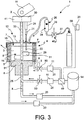
- reference numeral 1 globally denotes a system.
- system 1 is a system for the injection of semisolid metal 3 into a mould 2.
- said mould 2 comprises a mould chamber 16 suitable to receive the metal through a mould injection mouth 17.
- said system comprises at least one press device 4 for pressure injecting metal 3 in said mould 2.
- said at least one press device comprises a cylinder 5 having a substantially vertical axis X-X and a mouth 15 for coupling to the injection mouth 17 of said mould 2 as well as a thrust piston 6 accommodated within said cylinder, defining with said cylinder an injection chamber 7 suitable to contain molten metal 10.
- said cylinder 5 has passageways 8 or inner ducts or a circuit of ducts to receive cooling fluid 9 capable of cooling said molten metal 10 poured into said injection chamber 7 converting it into semisolid metal 3.
- a cup 18 for drawing the molten metal 10 is suitable for drawing metal and pour it into said injection chamber 7.
- said system comprises a positioning device 11.
- said positioning device 11 supports a blending device 12, and said blending device 12 has an active portion 14 and is associated with a hood or cover 13 suitable for closing said injection chamber 7.
- said positioning device 11 is arranged to selectively position said blending device 12 with said active portion 14 within said injection chamber 7 and level the temperature of the semisolid metal 3 and simultaneously to position said hood or cover 13 to temporarily close said mouth 15 coupling the press device 4 to mould 2.
- an actuating device 19 selectively acts on said thrust piston 6 to inject said semisolid metal 3 into said mould 2 when the coupling mouth 15 of the injection chamber 7 is opened and connected to the injection mouth 17 of said mould 2.
- said system comprises a metal temperature detecting device 21 having an active portion 22 thereof.
- said metal temperature detecting device 21 is associated with said hood or cover 13 for selectively dipping the active portion 22 thereof into the molten or semisolid metal 10, 3 when the hood or cover 13 is arranged to close the mouth coupling the cylinder to mould 15.
- said metal temperature detecting device 21 is connected to a control device 23 of system 1. According to an embodiment, said metal temperature detecting device 21 is connected to an actuating device 24 that moves the probe during the insertion of the temperature device 21 into the injection chamber 7 and the withdrawal of the temperature device 21 from the injection chamber 7.
- said thrust piston 6 comprises passageways 25 for receiving cooling fluid 9 for cooling said molten metal 10.
- said passageways 8, 25 of said cylinder and said piston are in fluid connection with a cooling circuit connected to a flow adjustment device of the cooling fluid 9 and to a cooling fluid tank 54.
- said flow adjustment device of the cooling fluid 9 is operated in a controlled mode.
- said system comprises a temperature detection device 20 for the cooling fluid 9 provided within the cooling passageways 8, 25 of cylinder 5 and/or of the thrust piston 6, preferably but not necessarily downstream of the cylinder and of the piston.
- said cooling fluid temperature detection device 20 is operatively connected to a control device of the system 23.
- said flow adjustment device 9 of the cooling fluid is operated in a feedback controlled mode with said cooling fluid temperature detection device 20.
- said hood or cover 13 is associated with a feeding device 26 of inert gas 27, such as for example but not necessarily nitrogen, into the injection chamber 7.
- said inert gas feeding device 26 comprises an adjustment device 28 for the gas flow to be injected in the injection chamber 7, preferably but not necessarily operated in a controlled mode.
- said blending device 12 comprises an impeller 29 having a substantially vertical X-X rotary shaft 33 and operated by a controlled actuator 30 operatively connected to a control device of the system 23, preferably though not necessarily in a feedback mode.
- said impeller 29 comprises at least one blade 31, preferably but not necessarily two blades 31.
- each blade 31 comprises an extension 32 substantially radial to shaft 33 and a rounded free end.
- said impeller 29 comprises helical blades.
- said impeller 29 has a surface treatment that reduces the adhesion of the molten metal 10.
- said impeller 29 is made of a material that reduces the adhesion of the molten metal for example though not necessarily of ceramic material.
- said system comprises a filter 35 for impurities or oxides present in the molten metal 10.
- Said filter 35 is arranged between the cup for drawing and pouring the metal 18 and the injection chamber 7.
- said filter 35 comprises an intake duct for the molten metal, for example an intake channel 36, which is arranged such as to receive the molten metal from cup 18 and provided with a pouring end 37 opposite to the injection chamber 7 for the molten metal to be caused to flow into chamber 7.
- said filter 35 has in the proximity of the pouring end 37 thereof a filter portion 38 provided with passageways suitable to retain impurities and/or oxides and cause the molten metal to flow, for example though not necessarily a filter portion 38 made from ceramic material and/or comprising silicon carbides.
- said filter 35 is a disposable component that can be replaced at each pour, or after a limited number thereof, of molten metal 10 into the injection chamber 7.
- said filter is positioned in the proximity of the injection chamber so that the cup can pour the molten metal therein through the same filter from a positioning device 55, for example a robot.
- a controlled actuator 30 for example though not necessarily a feedback actuator with a temperature signal and/or a timer, controls the movements of the blending device 12.
- a controlled actuator 24 for example though not necessarily a feedback actuator with a switch for closing the hood or cover and/or a switch for changing the system operating conditions, controls the movements of the metal temperature detecting device 21.
- a controlled actuator 39 for example though not necessarily a feedback actuator with a switch for closing and opening the hood or cover, controls the inert gas inlet device within the injection chamber 26, for example, though not necessarily, it controls the adjustment of a shut-off solenoid valve 40 of the intake flow of inert gas 27.
- a controlled actuator 41 for example though not necessarily a feedback actuator with a switch or timer of completed-filling of the injection chamber 7 and/or of completed-pour of the molten metal from cup 18 and/or of positioning of the press device 4 in the system, controls the positioning of the hood or cover 13 in order to either close or open the mouth coupling the cylinder to mould 15.
- a controlled actuator 42 for example though not necessarily a feedback actuator with a switch or timer of completed-mixing of the metal within the injection chamber 7 and/or of opening of the hood or cover 13 and/or of positioning of the press device 4 within the system, controls the positioning of the press device 4 with the coupling mouth thereof of cylinder 15 coupled to the injection mouth 17 of mould 2.
- a controlled actuator 42 for example though not necessarily a feedback actuator with a device for detecting the pressure exerted by the thrust piston 44, controls the forward movement of the thrust piston 6 to inject the semisolid metal 3 into the mould chamber 16 and to maintain the pressure until the metal has solidified.
- said mould 2 comprises several opening mould portions 46, 47 to remove the solidified piece 48.
- a controlled actuator 45, 56 controls the closure or opening of the openable mould portions 46, 47 for the closure to form the mould chamber 16 or for the opening to remove the solidified piece 48.
- a controlled actuator 49 for example though not necessarily a feedback actuator with a temperature detection device of the cooling fluid of the cylinder and/or the piston, preferably though not necessarily arranged downstream of the cylinder and/or the thrust piston, controls the splitting of a control solenoid valve 50 of the cooling fluid flow of cylinder 5 and/or piston 6.
- a controlled actuator 30 of the feedback blending device 12 in continuous or sample measurement or upon any change in the operating conditions of the metal temperature system.
- a carousel 52 is comprised for supporting a plurality of press devices 4 with injection chambers 7 thereof formed by the relative cylinders 5 and piston 6.
- said stations are equally spaced and simultaneously allow to load a molten metal load, close hood or cover, cool and mix the metal until it is semisolid and approach the mould to inject the semisolid metal.
- a hood or cover 13 for a system 1 for injecting semisolid metal 3 into a mould 2 wherein said mould 2 comprises a mould chamber 16 suitable for receiving the metal through a mould injection mouth 17 and said system comprises at least one press device 4 for the pressure-injection of metal 3 in said mould 2, wherein said at least one press device 4 comprises a substantially vertical axis X-X cylinder 5 and a mouth 15 for coupling to the injection mouth 17 of said mould 2 and a thrust piston 6 accommodated within said cylinder, defining with said cylinder an injection chamber 7 suitable for containing molten metal 10, said hood or cover 13 being supported by a positioning device 11, wherein said positioning device 11 further supports a blending device 12, said blending device 12 having an active portion 14 and being associated with said hood or cover 13 and wherein said positioning device 11 being arranged for selectively positioning said blending device 12 with said active portion 14 within said injection chamber 7 and levelling the temperature of the semisolid metal 3, simultaneously positions said hood or cover 13 to temporarily close said mouth 15 coupling the press device
- this system is used for processing semisolid metal, for example aluminium or aluminium alloy.
- said system is provided with at least one press device 4 associable with said mould for pressure injecting metal 3 in said mould 2.
- said at least one press device comprising a cylinder 5 having a substantially vertical axis X-X and a mouth 15 for coupling to the injection mouth 17 of said mould 2 and a thrust piston 6 accommodated within said cylinder, defining with said cylinder an injection chamber 7 suitable to contain molten metal 10.
- said method comprises the steps of:
- a further step is provided for detecting the temperature of the metal contained within the injection chamber 7.
- a metal temperature detecting device 21 is used, provided with an active portion 22 and the active portion 22 of the device is dipped into the molten or semisolid metal 10, 3 when the hood or cover 13 is arranged to close the mouth coupling the cylinder to mould 15.
- the temperature detected of the metal contained within the injection chamber 7 is used for checking the operating steps of system 1.
- the temperature measurement of the metal contained within the injection chamber 7 is used to establish, when a predetermined or optimum temperature is achieved, the interruption of the metal blending and injection chamber opening step with the removal of the blending device 12.
- the metal temperature is detected and the temperature is checked in order to reach a predetermined or optimum temperature by detecting the time used to blend and cool the metal to optimum condition and storing the information of the time required to blend and cool such as to be capable of using this information during successive system operating cycles thereby avoiding to use the step of detecting the temperature of the metal contained within the injection chamber at each work cycle.
- a flow is adjusted of cooling fluid 9 provided within passageways 8, 25 provided within the cylinder and/or within the thrust piston. According to an embodiment, said adjustment is carried out in a controlled mode by detecting the temperature of the metal contained within the injection chamber 7. According to an embodiment, the cooling fluid flow is adjusted such that the temperature of the molten metal contained within the injection chamber 7 reaches a predefined or optimum temperature level within a predetermined or limit cycle time.
- the adjustment of the cooling fluid 9 flow is carried out by detecting the temperature of the cooling fluid 9 provided within the cooling passageways 8, 25 of cylinder 5 and/or thrust piston 6.
- the gas flow 28 to be fed into the injection chamber 7 is adjusted, preferably though not necessarily so as to achieve a predetermined or optimum flow.
- a further step is provided for controlling by means of a controlled actuator 30 the blending device 12 comprising an impeller 29 such as to adjust the rotation of said impeller, preferably though not necessarily in a feedback mode for example on the rotation speed of the impeller.
- the molten metal contained within the injection chamber 7 is blended substantially in the circumferential direction using elements transversal to the walls of cylinder 5, preferably though not necessarily by mixing along two circumferential pathways transversal to the cylinder walls and placed at two different heights relative to the bottom of the injection chamber 7 or crown of the thrust piston 6.
- the metal is blended along circumferential pathways substantially transversal to cylinder 5 leaving a predetermined space between said wall of cylinder 5 and the blending device 12, and/or a predetermined space between the blending device 12 and the thrust piston 6.
- the metal temperature; the rotation speed of the blending device 12; the optimum flow of the inert gas injected into the injection chamber 7; the optimum temperature of the cooling fluid cycling within cylinder 5 and optionally of the thrust piston 6; and/or an evaluation of the flow rate of the cooling fluid are measured.
- Said cycle time is set for the system for successive working steps.
- the cycle time of the blending and cooling step is recalculated only when the system parameters are changed, for example though not necessarily, using the metal temperature contained within the injection chamber and consequently by changing the blending device moving speed parameters, of the inert gas flow, of temperature or flow of the cooling fluid contained within the cylinder and/or within the thrust piston.
- the molten metal 10 is filtered to eliminate the impurities and/or oxides that may be present in the metal.
- the metal poured from the cup into the injection chamber is filtered by means of a disposable filter, replacing said filter 35 every one or limited number or pours of the molten metal 10 into the injection chamber 7.
- the molten metal is blended by controlling the blending device 12 in a feedback mode using a temperature signal of the molten metal and/or a time signal of duration of the blending step.
- the hood or cover is moved by operating the positioning device as a function of the operating conditions of the system, for example, though not necessarily, by means of feedback operation as a function of the temperature signal of the metal provided within the injection chamber.
- the feeding of inert gas into the injection chamber is controlled by controlling a splitting device for the inert gas flow by means of a positioning signal of the hood and/or cover.
- a rotation and/or translation step is provided which shifts the injection chamber to a second station.
- a further step is provided for injecting inert gas into the injection chamber closed by the hood or cover.
- a further step is provided for measuring the temperature of the metal contained within the injection chamber.
- the step is provided of rotation and/or translation of the injection chamber at a further station.
- said stations are provided in a carrousel machine and the step is provided of moving said carrousel machine in a controlled mode, preferably though not necessarily in a feedback mode.
- the process is divided into two macro steps:
- the hood or cover for closing the injection chamber during the cooling and blending, it is possible to ensure the exclusion of impurity entrapment.
- the injection or washing of the atmosphere of the injection chamber closed by the cover with inert gas in overpressure allows the exclusion of not only impurities but also of oxides in the semisolid metal and thus in the casting to be even more ensured during the blending of the metal in semisolid metal, also preventing the forming of dangerous films.
- a 22 liter/min rate is optimum for washing an injection chamber having dimensions of 180 mm diameter and 150 mm depth, wherein about 1/3 volume remains as free atmosphere.
- a filter between the cup and the injection chamber for example preferably a disposable filter, it is possible to ensure the absence of oxide films that in the chamber and in the casting would bend on themselves, creating very harmful structural discontinuities.
- the metal temperature measurement in the injection chamber it is possible to check the semisolid metal forming process adjusting the cycle times or other system operating parameters to obtain a metal having optimum conditions.
- controlling the semisolid metal temperature allows the mould cavity to be fully filled allowing this method to be used also for castings with very complex shapes and/or allows the solid fraction provided in the metal to be maximized, for example achieving even 40%-50% by volume and/or allows the semisolid metal blending times to be changed according, for example, to the alloy in any case ensuring a casting with optimum metallurgic quality.
- the aluminum alloy temperature may be set to 590 °C and accordingly the blending cycle times and the cooling fluid flow rate may be calculated, optimizing the cycle times so that they are shorter than a predetermined limit time (for example 12 seconds).
- a predetermined limit time for example 12 seconds
Landscapes
- Engineering & Computer Science (AREA)
- Mechanical Engineering (AREA)
- Casting Support Devices, Ladles, And Melt Control Thereby (AREA)
- Injection Moulding Of Plastics Or The Like (AREA)
- Molds, Cores, And Manufacturing Methods Thereof (AREA)
- Agricultural Chemicals And Associated Chemicals (AREA)
Claims (15)
- Système (1) pour injecter du métal semi-solide (3) dans un moule (2), comprenant :- ledit moule (2) comprenant une chambre de moule (16) appropriée pour recevoir le métal à travers une bouche d'injection de moule (17) ;- au moins un dispositif de presse (4) pour injecter par pression du métal (3) dans ledit moule (2) ;- ledit au moins un dispositif de presse comprenant un cylindre (5) possédant un axe vertical (X-X) et une bouche (15) pour un accouplement avec la bouche d'injection (17) dudit moule (2) et un piston de poussée (6) accueilli à l'intérieur dudit cylindre, définissant avec ledit cylindre une chambre d'injection (7) appropriée pour contenir du métal fondu (10) ;- ledit cylindre (5) possédant des voies de passage (8) pour recevoir du fluide de refroidissement (9) dudit métal fondu (10) versé dans ladite chambre d'injection (7) de sorte à le convertir en du métal semi-solide (3) ;- une coupelle (18) pour extraire le métal fondu (10) et verser ce dernier dans ladite chambre d'injection (7) ;- un dispositif de positionnement (11) ;- ledit dispositif de positionnement (11) supportant un dispositif de mélange (12), ledit dispositif de mélange (12) possédant une partie active (14) et étant associé à un capot ou couvercle (13) ;- ledit dispositif de positionnement (11) étant conçu pour positionner sélectivement ledit dispositif de mélange (12) avec ladite partie active (14) dans ladite chambre d'injection (7) et rendre uniforme la température du métal semi-solide (3) et pour positionner simultanément ledit capot ou couvercle (13) de sorte à fermer provisoirement ladite bouche (15) accouplant le dispositif de presse (4) avec le moule (2) ;- un dispositif d'actionnement (19) qui agit sélectivement sur ledit piston de poussée (6) pour injecter ledit métal semi-solide (3) dans ledit moule (2) lorsque la bouche d'accouplement (15) de la chambre d'injection (7) est ouverte et reliée à la bouche d'injection (17) dudit moule (2).
- Système selon la revendication 1, comprenant un dispositif de détection de température de métal (21), qui possède une partie active (22), ledit dispositif de détection de température de métal (21) étant associé audit capot ou couvercle (13) pour plonger sélectivement la partie active (22) de celui-ci dans le métal fondu ou semi-solide (10, 3) lorsque le capot ou couvercle (13) est agencé de sorte à fermer la bouche accouplant le cylindre au moule (15) et dans lequel ledit dispositif de détection de température de métal (21) est relié à un dispositif d'actionnement (24) qui déplace la sonde au cours de l'insertion du dispositif de température (21) dans la chambre d'injection (7) et du retrait du dispositif de température (21) hors de la chambre d'injection (7).
- Système selon la revendication 1 ou 2, dans lequel ledit piston de poussée (6) comprend des voies de passage (25) pour recevoir du fluide de refroidissement (9) pour refroidir ledit métal fondu (10) et dans lequel lesdites voies de passage (8, 25) dudit cylindre et dudit piston sont en communication fluidique avec un circuit de refroidissement relié à un dispositif de réglage d'écoulement du fluide de refroidissement (9) et dans lequel ledit dispositif de réglage d'écoulement du fluide de refroidissement (9) est actionné selon un mode commandé.
- Système selon la revendication 3, comprenant un dispositif de détection de température (20) pour le fluide de refroidissement (9) fourni à l'intérieur des voies de passage de refroidissement (8, 25) du cylindre (5) et/ou du piston de poussée (6), et dans lequel ledit dispositif de détection de température (20) est fonctionnellement relié à un dispositif de commande (23) ; et dans lequel ledit dispositif de réglage d'écoulement du fluide de refroidissement (9) est actionné selon un mode commandé par rétroaction avec ledit dispositif de détection de température (20).
- Système selon une quelconque revendication précédente, dans lequel ledit capot ou couvercle (13) est associé à un dispositif (26) pour l'alimentation d'un gaz inerte (27) dans la chambre d'injection (7), dans lequel ledit dispositif d'injection de gaz inerte (26) comprend un dispositif de réglage (28) pour l'écoulement de gaz à injecter dans la chambre d'injection (7).
- Système selon une quelconque revendication précédente, dans lequel ledit dispositif de mélange (12) comprend un agitateur (29) possédant un arbre rotatif (33) vertical (X-X) et actionnée par un actionneur commandé (30) fonctionnellement relié à un dispositif de commande du système (23) et dans lequel ledit agitateur (29) comprend au moins une aube (31), et dans lequel chaque aube (31) comprend une extension (32) radiale par rapport à l'arbre (33) et une extrémité libre arrondie.
- Système selon une quelconque revendication précédente, dans lequel un filtre (35) est compris pour les impuretés ou oxydes présents dans le métal fondu (10), qui est agencé entre la coupelle (18) destinée à extraire et verser le métal et la chambre d'injection (7).
- Système selon une quelconque revendication précédente, comprenant un actionneur commandé (30) qui commande les mouvements du dispositif de mélange (12).
- Système selon une quelconque revendication précédente, comprenant un carrousel (52) qui supporte une pluralité de dispositifs de presse (4), les chambres d'injection (7) de ceux-ci étant formées par le piston (6) du cylindre (5) concerné.
- Procédé pour l'injection de métal semi-solide (3) dans un moule (2), dans lequel :- ledit moule (2) comprend une chambre de moule (16) appropriée pour recevoir le métal à travers une bouche d'injection de moule (17) ;- au moins un dispositif de presse (4) est fourni qui peut être associé audit moule pour l'injection par pression de métal (3) dans ledit moule (2) ;- ledit au moins un dispositif de presse comprenant un cylindre (5) possédant un axe vertical (X-X) et une bouche d'accouplement (15) au niveau de la bouche d'injection (17) dudit moule (2) et un piston de poussée (6) accueilli à l'intérieur dudit cylindre, définissant avec ledit cylindre une chambre d'injection (7) appropriée pour contenir du métal fondu (10) ;ledit procédé comprenant les étapes de :- l'extraction de métal fondu (10) au moyen d'une coupelle (18) et le déversement dudit métal fondu à l'intérieur de ladite chambre d'injection (7) ;- le support au moyen d'un dispositif de positionnement (11) d'un capot ou couvercle (13) et d'un dispositif de mélange (12) associé audit capot,- le positionnement d'une partie active (14) dudit dispositif de mélange (12) à l'intérieur de ladite chambre d'injection (7) et simultanément- le positionnement dudit capot ou couvercle (13) de sorte à fermer provisoirement ladite bouche (15) accouplant le dispositif de presse (4) au moule (2) ;- et simultanément le refroidissement dudit métal fondu (10) disposé à l'intérieur de ladite chambre d'injection au moyen d'un fluide de refroidissement (9) fourni à l'intérieur de voies de passage (8) destinées à recevoir le fluide de refroidissement fourni à l'intérieur dudit cylindre (5) et simultanément- le mélange dudit métal fondu (10) versé dans ladite chambre d'injection (7) avec ladite partie active (14) dudit dispositif de mélange (12), tandis que ledit capot ou couvercle (13) ferme ladite bouche (15) accouplant le dispositif de presse (4)- la transformation dudit métal en du métal semi-solide (3) et l'égalisation de la température du métal semi-solide (3) puis par la suite- l'injection dudit métal semi-solide (3) avec un dispositif d'actionnement (19) qui agit sélectivement sur ledit piston de poussée (6) à l'intérieur dudit moule (2) lorsque la bouche d'accouplement (15) de la chambre d'injection (7) est ouverte et reliée à la bouche d'injection (17) dudit moule (2).
- Procédé selon la revendication 10, dans lequel est comprise l'étape supplémentaire de :- la détection de la température du métal contenu à l'intérieur de la chambre d'injection (7) ;dans lequel l'utilisation d'un dispositif de détection de température de métal (21) est fournie, qui est doté d'une partie active (22) et la partie active (22) du dispositif est plongée dans le métal fondu ou semi-solide (10, 3) tandis que le capot ou couvercle (13) est disposé de sorte à fermer la bouche accouplant le cylindre au moule (15) ;
et dans lequel la mesure de la température du métal contenu à l'intérieur de la chambre d'injection (7) est utilisée pour établir, lorsqu'une température prédéterminée ou optimale est atteinte, l'interruption de l'étape de mélange du métal et l'ouverture de la chambre d'injection par le retrait du dispositif de mélange (12). - Procédé selon une quelconque revendication 10 à 11, dans lequel est fournie l'étape supplémentaire de :- l'alimentation d'un gaz inerte (27) dans la chambre d'injection (7) provisoirement fermée par le capot ou couvercle (13).
- Procédé selon une quelconque revendication 10 à 12, dans lequel est fournie l'étape supplémentaire de :- la commande, au moyen d'un actionneur commandé (30), du dispositif de mélange (12) comprenant un agitateur (29) de sorte à régler la rotation dudit agitateur selon un mode à rétroaction sur la vitesse de rotation de l'agitateur et dans lequel le métal fondu contenu à l'intérieur de la chambre d'injection (7) est mélangé dans la direction circonférentielle au moyen d'éléments transversaux aux parois du cylindre (5) ;ou dans lequel le métal est mélangé le long de voies de passage circonférentielles transversales au cylindre (5) laissant un espace prédéterminé entre ladite paroi du cylindre (5) et le dispositif de mélange (12).
- Procédé selon une quelconque revendication 10 à 13, dans lequel sont fournies les étapes supplémentaires de :- la définition d'une température optimale du métal semi-solide (3) contenu à l'intérieur de la chambre d'injection (7), par l'utilisation d'aluminium à une température allant de 580 à 600 °C, de préférence 590 °C,- le calibrage du système (1) de sorte à obtenir un temps de cycle de refroidissement et une uniformité de la température du métal semi-solide (3) inférieurs à un temps de cycle limite ;- dans ces conditions : la température du métal ; la vitesse de rotation du dispositif de mélange (12); l'écoulement optimal du gaz inerte injecté dans la chambre d'injection (7) ; la température optimale du fluide de refroidissement circulant à l'intérieur du cylindre (5) et optionnellement du piston de poussée (6) ; ou une évaluation de la vitesse d'écoulement du fluide de refroidissement sont mesurés ;- ledit temps de cycle est établi pour des étapes de travail successives ; dans lequel le temps de cycle de l'étape de mélange et de refroidissement est recalculé uniquement lorsque les paramètres de système sont modifiés, au moyen de la température du métal contenu à l'intérieur de la chambre d'injection et en modifiant par la suite les paramètres de vitesse de déplacement du dispositif de mélange, de l'écoulement de gaz inerte, de la température ou de l'écoulement du fluide de refroidissement contenu à l'intérieur du cylindre et/ou à l'intérieur du piston de poussée.
- Procédé selon une quelconque revendication 10 à 14, dans lequel un mouvement par étapes ou par postes ou par phases du système est fourni, dans lequel :- une première étape de chargement du métal fondu dans la chambre d'injection est fournie ;- une rotation et/ou une translation qui déplace la chambre d'injection vers un second poste est fournie ;- une seconde étape de fermeture avec le capot ou couvercle de la chambre d'injection et d'initiation du mélange et du refroidissement simultané du métal contenu à l'intérieur de la chambre d'injection est fournie ;
dans lequel l'étape supplémentaire est fournie, de l'injection du gaz inerte à l'intérieur de la chambre d'injection fermée par le capot ou couvercle et de la mesure de la température du métal contenu à l'intérieur de la chambre d'injection ;- par la suite, est fournie l'étape de rotation et/ou de translation de la chambre d'injection au niveau d'un autre poste ;- l'action d'injection est ensuite fournie par le déplacement du piston de poussée de la chambre d'injection lorsque cette dernière est accouplée au moule.
Priority Applications (1)
| Application Number | Priority Date | Filing Date | Title |
|---|---|---|---|
| EP17166771.0A EP3216541A1 (fr) | 2011-05-20 | 2012-05-15 | Système et procédé d'injection d'aluminium semi-solide dans un moule |
Applications Claiming Priority (2)
| Application Number | Priority Date | Filing Date | Title |
|---|---|---|---|
| IT000903A ITMI20110903A1 (it) | 2011-05-20 | 2011-05-20 | Impianto e metodo per l'iniezione in stampo di alluminio semisolido |
| PCT/IB2012/052422 WO2012160479A1 (fr) | 2011-05-20 | 2012-05-15 | Système et procédé pour injecter de l'aluminium semi-solide dans un moule |
Related Child Applications (2)
| Application Number | Title | Priority Date | Filing Date |
|---|---|---|---|
| EP17166771.0A Division-Into EP3216541A1 (fr) | 2011-05-20 | 2012-05-15 | Système et procédé d'injection d'aluminium semi-solide dans un moule |
| EP17166771.0A Division EP3216541A1 (fr) | 2011-05-20 | 2012-05-15 | Système et procédé d'injection d'aluminium semi-solide dans un moule |
Publications (2)
| Publication Number | Publication Date |
|---|---|
| EP2709781A1 EP2709781A1 (fr) | 2014-03-26 |
| EP2709781B1 true EP2709781B1 (fr) | 2017-07-05 |
Family
ID=44555086
Family Applications (2)
| Application Number | Title | Priority Date | Filing Date |
|---|---|---|---|
| EP12731688.3A Active EP2709781B1 (fr) | 2011-05-20 | 2012-05-15 | Système et procédé pour injecter de l'aluminium semi-solide dans un moule |
| EP17166771.0A Withdrawn EP3216541A1 (fr) | 2011-05-20 | 2012-05-15 | Système et procédé d'injection d'aluminium semi-solide dans un moule |
Family Applications After (1)
| Application Number | Title | Priority Date | Filing Date |
|---|---|---|---|
| EP17166771.0A Withdrawn EP3216541A1 (fr) | 2011-05-20 | 2012-05-15 | Système et procédé d'injection d'aluminium semi-solide dans un moule |
Country Status (5)
| Country | Link |
|---|---|
| US (1) | US9724753B2 (fr) |
| EP (2) | EP2709781B1 (fr) |
| CN (1) | CN103717327B (fr) |
| IT (1) | ITMI20110903A1 (fr) |
| WO (1) | WO2012160479A1 (fr) |
Families Citing this family (12)
| Publication number | Priority date | Publication date | Assignee | Title |
|---|---|---|---|---|
| US10029366B2 (en) * | 2014-11-21 | 2018-07-24 | Canon Kabushiki Kaisha | Control device for motor drive device, control device for multi-axial motor, and control method for motor drive device |
| US20180044761A1 (en) * | 2015-03-10 | 2018-02-15 | Honeywell International Inc. | Method of purifying and casting materials |
| CN104785786B (zh) * | 2015-04-24 | 2017-04-05 | 江苏科技大学 | 一种送浆式金属部件增材制造方法及装置 |
| CN104907527A (zh) * | 2015-06-17 | 2015-09-16 | 深圳领威科技有限公司 | 半固态制浆设备、半固态制浆系统和半固态制浆方法 |
| CN105127398B (zh) * | 2015-09-09 | 2018-02-23 | 东莞市隆盛智能装备有限公司 | 多工位全自动供料装置 |
| US20200038946A1 (en) * | 2015-11-03 | 2020-02-06 | Fujian Rheomet Light Metal Co., Ltd. | Aluminum alloy semi-solid molding method and device |
| IT201700008841A1 (it) | 2017-01-27 | 2018-07-27 | Fonderia Gattelli S R L | Macchina e metodo di pressocolata in semisolido |
| CN107457382B (zh) * | 2017-08-28 | 2023-04-28 | 广东工业大学 | 一种半固态流变压铸生产装置 |
| WO2019123223A1 (fr) * | 2017-12-20 | 2019-06-27 | Freni Brembo S.P.A. | Procédé de fabrication d'une préforme poreuse en carbure de silicium ayant une porosité contrôlée et préforme poreuse en carbure de silicium |
| CN109865812B (zh) * | 2019-03-29 | 2020-10-27 | 东北大学 | 一种金属流变净化压力成形设备 |
| CN113352519B (zh) * | 2021-05-26 | 2022-06-28 | 深圳市旭龙光电有限公司 | 一种有机玻璃浇注板生产用浇筑设备 |
| CN114309524A (zh) * | 2021-11-26 | 2022-04-12 | 深圳南科强正轻合金技术有限公司 | 半固态浆料的质量在线监测系统及方法 |
Family Cites Families (9)
| Publication number | Priority date | Publication date | Assignee | Title |
|---|---|---|---|---|
| US3954455A (en) | 1973-07-17 | 1976-05-04 | Massachusetts Institute Of Technology | Liquid-solid alloy composition |
| EP0937524A1 (fr) * | 1998-02-19 | 1999-08-25 | Fondarex S.A. | Procédé pour désaérer des moules à couler sous pression et dispositif à valve pour la mise en oeuvre de ce procédé |
| CA2338004A1 (fr) * | 1998-07-24 | 2000-02-03 | Charles E. Barron | Procede et appareil de moulage semi-solide |
| US6742567B2 (en) * | 2001-08-17 | 2004-06-01 | Brunswick Corporation | Apparatus for and method of producing slurry material without stirring for application in semi-solid forming |
| US6901991B2 (en) | 2002-01-31 | 2005-06-07 | Tht Presses Inc. | Semi-solid molding apparatus and method |
| US20030141033A1 (en) | 2002-01-31 | 2003-07-31 | Tht Presses Inc. | Semi-solid molding method |
| JP3549055B2 (ja) * | 2002-09-25 | 2004-08-04 | 俊杓 洪 | 固液共存状態金属材料成形用ダイカスト方法、その装置、半凝固成形用ダイカスト方法およびその装置 |
| US7441584B2 (en) * | 2006-03-02 | 2008-10-28 | T.H.T Presses, Inc. | Semi-solid molding method and apparatus |
| EP2462250B1 (fr) * | 2009-08-06 | 2017-03-29 | Rolls-Royce Corporation | Dispositif à filtre pour liquide |
-
2011
- 2011-05-20 IT IT000903A patent/ITMI20110903A1/it unknown
-
2012
- 2012-05-15 CN CN201280035682.9A patent/CN103717327B/zh active Active
- 2012-05-15 EP EP12731688.3A patent/EP2709781B1/fr active Active
- 2012-05-15 US US14/118,253 patent/US9724753B2/en active Active
- 2012-05-15 WO PCT/IB2012/052422 patent/WO2012160479A1/fr active Application Filing
- 2012-05-15 EP EP17166771.0A patent/EP3216541A1/fr not_active Withdrawn
Non-Patent Citations (1)
| Title |
|---|
| None * |
Also Published As
| Publication number | Publication date |
|---|---|
| EP2709781A1 (fr) | 2014-03-26 |
| CN103717327B (zh) | 2016-12-28 |
| EP3216541A1 (fr) | 2017-09-13 |
| WO2012160479A1 (fr) | 2012-11-29 |
| US20140182806A1 (en) | 2014-07-03 |
| US9724753B2 (en) | 2017-08-08 |
| ITMI20110903A1 (it) | 2012-11-21 |
| CN103717327A (zh) | 2014-04-09 |
Similar Documents
| Publication | Publication Date | Title |
|---|---|---|
| EP2709781B1 (fr) | Système et procédé pour injecter de l'aluminium semi-solide dans un moule | |
| US20080202644A1 (en) | Quiescent transfer of melts | |
| CN1733394B (zh) | 金属自动铸造装置及方法 | |
| US9381569B2 (en) | Vacuum or air casting using induction hot topping | |
| US8245759B2 (en) | Ladle for molten metal | |
| CN105149552A (zh) | 分体式熔铸一体化设备 | |
| RU2710240C2 (ru) | Оборудование для непрерывного или полунепрерывного литья металла с использованием усовершенствованных средств для заливки металла | |
| US6637496B1 (en) | Rotary casting system for pressurized casting machines | |
| EP1050353A1 (fr) | Procede et appareil pour la fabrication de metaux semi-solidifies | |
| CN108213383B (zh) | 一种半固态浆料制备方法及装置 | |
| KR20180046364A (ko) | 사출 성형기 | |
| CN112828264A (zh) | 一种带螺旋磁场的铸造装置和铸造方法 | |
| US8303890B2 (en) | Integrated quiescent processing of melts | |
| CN106834762B (zh) | 一种镍铝金属间化合物的真空熔炼装置 | |
| US4524817A (en) | Centrifugal casting unit for the production of precision castings | |
| WO2006021082A1 (fr) | Appareil de coulage de mousse métallique et procédés idoines | |
| GB2057937A (en) | Casting metals using bottom pouring | |
| WO2010078201A1 (fr) | Moulage en sable basse pression d'éléments de moteur à cylindres en alliage d'aluminium | |
| JPH07509664A (ja) | 部材の鋳造法およびその装置 | |
| JP2003311389A (ja) | 金属の鋳造方法とそれに用いる鋳造装置 | |
| US8418745B2 (en) | Pour ladle for molten metal | |
| JP4239160B2 (ja) | 低圧鋳造システム | |
| WO2021044111A1 (fr) | Appareil de coulage | |
| CN206356563U (zh) | 一种压铸合金双炉熔炼装置 | |
| CN113263168B (zh) | 一种浇勺浇注方法 |
Legal Events
| Date | Code | Title | Description |
|---|---|---|---|
| PUAI | Public reference made under article 153(3) epc to a published international application that has entered the european phase |
Free format text: ORIGINAL CODE: 0009012 |
|
| 17P | Request for examination filed |
Effective date: 20131120 |
|
| AK | Designated contracting states |
Kind code of ref document: A1 Designated state(s): AL AT BE BG CH CY CZ DE DK EE ES FI FR GB GR HR HU IE IS IT LI LT LU LV MC MK MT NL NO PL PT RO RS SE SI SK SM TR |
|
| DAX | Request for extension of the european patent (deleted) | ||
| 17Q | First examination report despatched |
Effective date: 20160211 |
|
| TPAC | Observations filed by third parties |
Free format text: ORIGINAL CODE: EPIDOSNTIPA |
|
| REG | Reference to a national code |
Ref country code: DE Ref legal event code: R079 Ref document number: 602012034185 Country of ref document: DE Free format text: PREVIOUS MAIN CLASS: B22D0017000000 Ipc: B22D0017120000 |
|
| GRAP | Despatch of communication of intention to grant a patent |
Free format text: ORIGINAL CODE: EPIDOSNIGR1 |
|
| RIC1 | Information provided on ipc code assigned before grant |
Ipc: B22D 17/30 20060101ALI20170130BHEP Ipc: B22D 17/12 20060101AFI20170130BHEP Ipc: B22D 17/00 20060101ALI20170130BHEP |
|
| INTG | Intention to grant announced |
Effective date: 20170228 |
|
| GRAS | Grant fee paid |
Free format text: ORIGINAL CODE: EPIDOSNIGR3 |
|
| GRAA | (expected) grant |
Free format text: ORIGINAL CODE: 0009210 |
|
| AK | Designated contracting states |
Kind code of ref document: B1 Designated state(s): AL AT BE BG CH CY CZ DE DK EE ES FI FR GB GR HR HU IE IS IT LI LT LU LV MC MK MT NL NO PL PT RO RS SE SI SK SM TR |
|
| REG | Reference to a national code |
Ref country code: GB Ref legal event code: FG4D |
|
| REG | Reference to a national code |
Ref country code: CH Ref legal event code: EP |
|
| REG | Reference to a national code |
Ref country code: AT Ref legal event code: REF Ref document number: 906238 Country of ref document: AT Kind code of ref document: T Effective date: 20170715 |
|
| REG | Reference to a national code |
Ref country code: IE Ref legal event code: FG4D |
|
| REG | Reference to a national code |
Ref country code: DE Ref legal event code: R096 Ref document number: 602012034185 Country of ref document: DE |
|
| REG | Reference to a national code |
Ref country code: NL Ref legal event code: MP Effective date: 20170705 |
|
| REG | Reference to a national code |
Ref country code: AT Ref legal event code: MK05 Ref document number: 906238 Country of ref document: AT Kind code of ref document: T Effective date: 20170705 |
|
| REG | Reference to a national code |
Ref country code: LT Ref legal event code: MG4D |
|
| PG25 | Lapsed in a contracting state [announced via postgrant information from national office to epo] |
Ref country code: AT Free format text: LAPSE BECAUSE OF FAILURE TO SUBMIT A TRANSLATION OF THE DESCRIPTION OR TO PAY THE FEE WITHIN THE PRESCRIBED TIME-LIMIT Effective date: 20170705 Ref country code: HR Free format text: LAPSE BECAUSE OF FAILURE TO SUBMIT A TRANSLATION OF THE DESCRIPTION OR TO PAY THE FEE WITHIN THE PRESCRIBED TIME-LIMIT Effective date: 20170705 Ref country code: NO Free format text: LAPSE BECAUSE OF FAILURE TO SUBMIT A TRANSLATION OF THE DESCRIPTION OR TO PAY THE FEE WITHIN THE PRESCRIBED TIME-LIMIT Effective date: 20171005 Ref country code: SE Free format text: LAPSE BECAUSE OF FAILURE TO SUBMIT A TRANSLATION OF THE DESCRIPTION OR TO PAY THE FEE WITHIN THE PRESCRIBED TIME-LIMIT Effective date: 20170705 Ref country code: FI Free format text: LAPSE BECAUSE OF FAILURE TO SUBMIT A TRANSLATION OF THE DESCRIPTION OR TO PAY THE FEE WITHIN THE PRESCRIBED TIME-LIMIT Effective date: 20170705 Ref country code: LT Free format text: LAPSE BECAUSE OF FAILURE TO SUBMIT A TRANSLATION OF THE DESCRIPTION OR TO PAY THE FEE WITHIN THE PRESCRIBED TIME-LIMIT Effective date: 20170705 Ref country code: NL Free format text: LAPSE BECAUSE OF FAILURE TO SUBMIT A TRANSLATION OF THE DESCRIPTION OR TO PAY THE FEE WITHIN THE PRESCRIBED TIME-LIMIT Effective date: 20170705 |
|
| PG25 | Lapsed in a contracting state [announced via postgrant information from national office to epo] |
Ref country code: RS Free format text: LAPSE BECAUSE OF FAILURE TO SUBMIT A TRANSLATION OF THE DESCRIPTION OR TO PAY THE FEE WITHIN THE PRESCRIBED TIME-LIMIT Effective date: 20170705 Ref country code: ES Free format text: LAPSE BECAUSE OF FAILURE TO SUBMIT A TRANSLATION OF THE DESCRIPTION OR TO PAY THE FEE WITHIN THE PRESCRIBED TIME-LIMIT Effective date: 20170705 Ref country code: LV Free format text: LAPSE BECAUSE OF FAILURE TO SUBMIT A TRANSLATION OF THE DESCRIPTION OR TO PAY THE FEE WITHIN THE PRESCRIBED TIME-LIMIT Effective date: 20170705 Ref country code: PL Free format text: LAPSE BECAUSE OF FAILURE TO SUBMIT A TRANSLATION OF THE DESCRIPTION OR TO PAY THE FEE WITHIN THE PRESCRIBED TIME-LIMIT Effective date: 20170705 Ref country code: GR Free format text: LAPSE BECAUSE OF FAILURE TO SUBMIT A TRANSLATION OF THE DESCRIPTION OR TO PAY THE FEE WITHIN THE PRESCRIBED TIME-LIMIT Effective date: 20171006 Ref country code: BG Free format text: LAPSE BECAUSE OF FAILURE TO SUBMIT A TRANSLATION OF THE DESCRIPTION OR TO PAY THE FEE WITHIN THE PRESCRIBED TIME-LIMIT Effective date: 20171005 Ref country code: IS Free format text: LAPSE BECAUSE OF FAILURE TO SUBMIT A TRANSLATION OF THE DESCRIPTION OR TO PAY THE FEE WITHIN THE PRESCRIBED TIME-LIMIT Effective date: 20171105 |
|
| REG | Reference to a national code |
Ref country code: DE Ref legal event code: R097 Ref document number: 602012034185 Country of ref document: DE |
|
| PG25 | Lapsed in a contracting state [announced via postgrant information from national office to epo] |
Ref country code: RO Free format text: LAPSE BECAUSE OF FAILURE TO SUBMIT A TRANSLATION OF THE DESCRIPTION OR TO PAY THE FEE WITHIN THE PRESCRIBED TIME-LIMIT Effective date: 20170705 Ref country code: DK Free format text: LAPSE BECAUSE OF FAILURE TO SUBMIT A TRANSLATION OF THE DESCRIPTION OR TO PAY THE FEE WITHIN THE PRESCRIBED TIME-LIMIT Effective date: 20170705 Ref country code: CZ Free format text: LAPSE BECAUSE OF FAILURE TO SUBMIT A TRANSLATION OF THE DESCRIPTION OR TO PAY THE FEE WITHIN THE PRESCRIBED TIME-LIMIT Effective date: 20170705 |
|
| PLBE | No opposition filed within time limit |
Free format text: ORIGINAL CODE: 0009261 |
|
| STAA | Information on the status of an ep patent application or granted ep patent |
Free format text: STATUS: NO OPPOSITION FILED WITHIN TIME LIMIT |
|
| PG25 | Lapsed in a contracting state [announced via postgrant information from national office to epo] |
Ref country code: SM Free format text: LAPSE BECAUSE OF FAILURE TO SUBMIT A TRANSLATION OF THE DESCRIPTION OR TO PAY THE FEE WITHIN THE PRESCRIBED TIME-LIMIT Effective date: 20170705 Ref country code: EE Free format text: LAPSE BECAUSE OF FAILURE TO SUBMIT A TRANSLATION OF THE DESCRIPTION OR TO PAY THE FEE WITHIN THE PRESCRIBED TIME-LIMIT Effective date: 20170705 Ref country code: SK Free format text: LAPSE BECAUSE OF FAILURE TO SUBMIT A TRANSLATION OF THE DESCRIPTION OR TO PAY THE FEE WITHIN THE PRESCRIBED TIME-LIMIT Effective date: 20170705 |
|
| 26N | No opposition filed |
Effective date: 20180406 |
|
| PG25 | Lapsed in a contracting state [announced via postgrant information from national office to epo] |
Ref country code: SI Free format text: LAPSE BECAUSE OF FAILURE TO SUBMIT A TRANSLATION OF THE DESCRIPTION OR TO PAY THE FEE WITHIN THE PRESCRIBED TIME-LIMIT Effective date: 20170705 |
|
| REG | Reference to a national code |
Ref country code: CH Ref legal event code: PL |
|
| REG | Reference to a national code |
Ref country code: BE Ref legal event code: MM Effective date: 20180531 |
|
| PG25 | Lapsed in a contracting state [announced via postgrant information from national office to epo] |
Ref country code: MC Free format text: LAPSE BECAUSE OF FAILURE TO SUBMIT A TRANSLATION OF THE DESCRIPTION OR TO PAY THE FEE WITHIN THE PRESCRIBED TIME-LIMIT Effective date: 20170705 |
|
| REG | Reference to a national code |
Ref country code: IE Ref legal event code: MM4A |
|
| PG25 | Lapsed in a contracting state [announced via postgrant information from national office to epo] |
Ref country code: CH Free format text: LAPSE BECAUSE OF NON-PAYMENT OF DUE FEES Effective date: 20180531 Ref country code: LI Free format text: LAPSE BECAUSE OF NON-PAYMENT OF DUE FEES Effective date: 20180531 |
|
| PG25 | Lapsed in a contracting state [announced via postgrant information from national office to epo] |
Ref country code: LU Free format text: LAPSE BECAUSE OF NON-PAYMENT OF DUE FEES Effective date: 20180515 |
|
| PG25 | Lapsed in a contracting state [announced via postgrant information from national office to epo] |
Ref country code: IE Free format text: LAPSE BECAUSE OF NON-PAYMENT OF DUE FEES Effective date: 20180515 Ref country code: FR Free format text: LAPSE BECAUSE OF NON-PAYMENT OF DUE FEES Effective date: 20180531 |
|
| PG25 | Lapsed in a contracting state [announced via postgrant information from national office to epo] |
Ref country code: BE Free format text: LAPSE BECAUSE OF NON-PAYMENT OF DUE FEES Effective date: 20180531 |
|
| PG25 | Lapsed in a contracting state [announced via postgrant information from national office to epo] |
Ref country code: MT Free format text: LAPSE BECAUSE OF NON-PAYMENT OF DUE FEES Effective date: 20180515 |
|
| PG25 | Lapsed in a contracting state [announced via postgrant information from national office to epo] |
Ref country code: TR Free format text: LAPSE BECAUSE OF FAILURE TO SUBMIT A TRANSLATION OF THE DESCRIPTION OR TO PAY THE FEE WITHIN THE PRESCRIBED TIME-LIMIT Effective date: 20170705 |
|
| PG25 | Lapsed in a contracting state [announced via postgrant information from national office to epo] |
Ref country code: PT Free format text: LAPSE BECAUSE OF FAILURE TO SUBMIT A TRANSLATION OF THE DESCRIPTION OR TO PAY THE FEE WITHIN THE PRESCRIBED TIME-LIMIT Effective date: 20170705 Ref country code: HU Free format text: LAPSE BECAUSE OF FAILURE TO SUBMIT A TRANSLATION OF THE DESCRIPTION OR TO PAY THE FEE WITHIN THE PRESCRIBED TIME-LIMIT; INVALID AB INITIO Effective date: 20120515 |
|
| PG25 | Lapsed in a contracting state [announced via postgrant information from national office to epo] |
Ref country code: MK Free format text: LAPSE BECAUSE OF NON-PAYMENT OF DUE FEES Effective date: 20170705 Ref country code: CY Free format text: LAPSE BECAUSE OF FAILURE TO SUBMIT A TRANSLATION OF THE DESCRIPTION OR TO PAY THE FEE WITHIN THE PRESCRIBED TIME-LIMIT Effective date: 20170705 |
|
| PG25 | Lapsed in a contracting state [announced via postgrant information from national office to epo] |
Ref country code: AL Free format text: LAPSE BECAUSE OF FAILURE TO SUBMIT A TRANSLATION OF THE DESCRIPTION OR TO PAY THE FEE WITHIN THE PRESCRIBED TIME-LIMIT Effective date: 20170705 |
|
| REG | Reference to a national code |
Ref country code: DE Ref legal event code: R081 Ref document number: 602012034185 Country of ref document: DE Owner name: BREMBO S.P.A., CURNO, IT Free format text: FORMER OWNER: FRENI BREMBO S.P.A., CURNO, BERGAMO, IT |
|
| P01 | Opt-out of the competence of the unified patent court (upc) registered |
Effective date: 20230526 |
|
| PGFP | Annual fee paid to national office [announced via postgrant information from national office to epo] |
Ref country code: IT Payment date: 20230405 Year of fee payment: 12 Ref country code: DE Payment date: 20230519 Year of fee payment: 12 |
|
| PGFP | Annual fee paid to national office [announced via postgrant information from national office to epo] |
Ref country code: GB Payment date: 20230524 Year of fee payment: 12 |