EP2708882A1 - Cleaning and grinding of sensor head - Google Patents
Cleaning and grinding of sensor head Download PDFInfo
- Publication number
- EP2708882A1 EP2708882A1 EP13183565.4A EP13183565A EP2708882A1 EP 2708882 A1 EP2708882 A1 EP 2708882A1 EP 13183565 A EP13183565 A EP 13183565A EP 2708882 A1 EP2708882 A1 EP 2708882A1
- Authority
- EP
- European Patent Office
- Prior art keywords
- electrode
- sensor
- ceramic stone
- liquid
- top surface
- Prior art date
- Legal status (The legal status is an assumption and is not a legal conclusion. Google has not performed a legal analysis and makes no representation as to the accuracy of the status listed.)
- Granted
Links
Images



Classifications
-
- B—PERFORMING OPERATIONS; TRANSPORTING
- B24—GRINDING; POLISHING
- B24B—MACHINES, DEVICES, OR PROCESSES FOR GRINDING OR POLISHING; DRESSING OR CONDITIONING OF ABRADING SURFACES; FEEDING OF GRINDING, POLISHING, OR LAPPING AGENTS
- B24B27/00—Other grinding machines or devices
- B24B27/033—Other grinding machines or devices for grinding a surface for cleaning purposes, e.g. for descaling or for grinding off flaws in the surface
-
- G—PHYSICS
- G01—MEASURING; TESTING
- G01N—INVESTIGATING OR ANALYSING MATERIALS BY DETERMINING THEIR CHEMICAL OR PHYSICAL PROPERTIES
- G01N27/00—Investigating or analysing materials by the use of electric, electrochemical, or magnetic means
- G01N27/26—Investigating or analysing materials by the use of electric, electrochemical, or magnetic means by investigating electrochemical variables; by using electrolysis or electrophoresis
- G01N27/28—Electrolytic cell components
- G01N27/30—Electrodes, e.g. test electrodes; Half-cells
- G01N27/38—Cleaning of electrodes
-
- G—PHYSICS
- G01—MEASURING; TESTING
- G01N—INVESTIGATING OR ANALYSING MATERIALS BY DETERMINING THEIR CHEMICAL OR PHYSICAL PROPERTIES
- G01N29/00—Investigating or analysing materials by the use of ultrasonic, sonic or infrasonic waves; Visualisation of the interior of objects by transmitting ultrasonic or sonic waves through the object
- G01N29/02—Analysing fluids
- G01N29/024—Analysing fluids by measuring propagation velocity or propagation time of acoustic waves
-
- G—PHYSICS
- G01—MEASURING; TESTING
- G01N—INVESTIGATING OR ANALYSING MATERIALS BY DETERMINING THEIR CHEMICAL OR PHYSICAL PROPERTIES
- G01N3/00—Investigating strength properties of solid materials by application of mechanical stress
- G01N3/08—Investigating strength properties of solid materials by application of mechanical stress by applying steady tensile or compressive forces
-
- G—PHYSICS
- G01—MEASURING; TESTING
- G01N—INVESTIGATING OR ANALYSING MATERIALS BY DETERMINING THEIR CHEMICAL OR PHYSICAL PROPERTIES
- G01N33/00—Investigating or analysing materials by specific methods not covered by groups G01N1/00 - G01N31/00
- G01N33/26—Oils; Viscous liquids; Paints; Inks
- G01N33/28—Oils, i.e. hydrocarbon liquids
- G01N33/2823—Raw oil, drilling fluid or polyphasic mixtures
Definitions
- the present invention relates to a method and an apparatus for cleaning and grinding sulfite sensor heads, and more specifically, to a method and an apparatus for cleaning and grinding sulfite sensor electrodes that reduces or eliminates electrode deformation and resultant changes in sensor signaling.
- Electrodes used to measure the presence of a particular substance in a liquid typically use metallic electrodes. Over a period of sensor use, these electrodes must be periodically cleaned.
- the electrode to be cleaned is a relatively thin metallic ring set in a plastic base.
- a planar surface of the rotating ceramic stone is brought into contact with an exposed electrode ring surface that extends beyond the surface of the plastic base. As such, the rotation of the ceramic stone removes residue from the exposed surface of the electrode ring.
- both the electrode ring wears down and the ceramic stone wears down. When the ceramic stone wears down, a groove is formed in the formerly planar surface thereof.
- the groove formed in the surface of the ceramic stone modifies the grinding and cleaning capabilities of the ceramic stone.
- effective grinding and cleaning of the electrode is compromised.
- the electrode becomes "smeared out” or deformed over a portion of the surface of the adjacent plastic base in which the electrode is set. This smearing or deformation of the electrode changes the surface area and functioning of the electrode. As such, electrode deformation compromises the electrode's signaling capabilities. Because compromises to electrode signaling are unacceptable as causing detection inaccuracies, electrodes and ceramic stones for cleaning and grinding must be replaced often.
- the electrode sensor and ceramic stone apparatus and method of the present invention achieve this objective as well as others, as described below.
- the present sensor useful for measuring the presence of a particular substance in a liquid includes an electrode manufactured from a metal, such as for example platinum, silver, gold or another metal of like characteristics.
- the metal electrode is fixed in a planar surface of a plastic base so as to be raised above the planar surface and amply exposed.
- a plastic base is preferred due to cost considerations.
- other materials could likewise be used as a base for fixing the electrode, such as ceramic or glass.
- the base in which the metal electrode is set is preferably of like dimension and design as that of the prior art so as to be readily interchangeable therewith on existing equipment without requiring associated equipment modification(s).
- the electrode fixed in the base is of an oval, elliptical, square or other non-circular shape, or non-symmetrically fixed circular shape.
- Sensors having electrodes of oval, elliptical, square or other non-circular shape, or non-symmetrically fixed circular shape allows for improved electrode wear and a prolonged sensor operational life over that of the prior art sensor.
- the present sensor is useful to detect and quantify an amount of a substance in a liquid, such as for example an amount of ions in a liquid or slurry or an amount of sulfite in water.
- residue builds on the surface of the sensor electrode.
- the electrode requires cleaning for residue removal therefrom to ensure proper and accurate sensor operation and function.
- the electrode is contacted with a relatively flat or planar contact surface of a rotating ceramic stone.
- the rotating ceramic stone is commonly referred to as a grinding and cleaning stone. Contact with the ceramic stone abrades the residue so as to again expose a clean electrode surface.
- the planar surface of the ceramic stone contacting the electrodes is worn more evenly so as to reduce or eliminate groove formation therein.
- deformation or "smearing" of the metal electrode cleaned thereby is likewise reduced or eliminated.
- the useful operating life of both the sensor and the ceramic stone are significantly extended. Extending the useful operating life of both the sensor and the ceramic stone reduces both capital and operational costs associated therewith.
- the present sensor for detection and measurement of a particular substance present in a liquid comprises a base with an interior edge, an exterior edge and a top surface extending between the interior edge and the exterior edge, with a non-circular or non-symmetrical electrode fixed on said top surface for detection and measurement of a particular substance present in a liquid in which said sensor is submersed.
- the sensor base is manufactured from a plastic, glass or ceramic material.
- the sensor electrode is manufactured from a metal, such as from silver, gold, platinum or a combination thereof.
- the electrode is of a non-circular shape, such as oval, elliptical, square or an oscillating form. Alternatively, an electrode of circular shape may be used if non-symmetrically fixed to the sensor base.
- An example of a particular substance detected and measured by the sensor is sulfite present in water or ions present in a liquid or slurry.
- a method of using the present sensor for detection and measurement of a particular substance present in a liquid comprises submerging the sensor comprising a base with an interior edge, an exterior edge, a top surface extending between the interior edge and the exterior edge, and a non-circular or non-symmetrically fixed electrode on said top surface, in a liquid for detection and measurement of a particular substance present in the liquid and periodically cleaning residue from the electrode using a rotating ceramic stone.
- the sensor base is manufactured from a plastic, glass or ceramic material.
- the electrode is manufactured from a metal, such as silver, gold, platinum or a combination thereof.
- the non-circular electrode is oval, elliptical, square or an oscillating form. Alternatively, an electrode of circular shape may be used if non-symmetrically fixed to the sensor base.
- An example of a particular substance detected and measured by the sensor is sulfite present in water or ions present in a liquid or slurry.
- a method of cleaning and grinding the present sensor electrode comprises attaching a ceramic stone offset from center to a rotating arm so as to cause the ceramic stone to follow a non-circular path around the rotating arm, and contacting a sensor electrode with a contact surface of the ceramic stone for cleaning and grinding of residue from the sensor electrode with reduced wear or prevention of grooved wear of the contact surface.
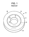
- FIGURE 1 is a top perspective view of an electrode sensor of the prior art.
- FIGURE 2 is a top perspective view of the bottom of a worn rotating ceramic stone of the prior art.
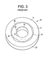
- FIGURE 3 is a top perspective view of the electrode sensor of FIGURE 1 after having been contacted with the worn ceramic stone of FIGURE 2 .
- FIGURE 4 is a top perspective view of a sensor according to the present disclosure.
- FIGURE 5 is a top perspective view of another embodiment of a sensor according to the present disclosure.
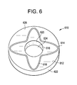
- FIGURE 6 is a top perspective view of another embodiment of a sensor according to the present disclosure.
- Sensor 10 comprises a plastic base 12 defined by an exterior side surface 22 and an interior side surface 20.
- Interior side surface 20 defines a center aperture 24 through base 12.
- Extending between exterior side surface 22 and interior side surface 20 of base 12 is top surface 26 and opposed bottom surface (not shown).
- An interior edge 16 defines the intersection of top surface 26 and interior side surface 20.
- an exterior edge 14 defines the intersection of top surface 26 and exterior side surface 22.
- Fixed in top surface 26 is a circular electrode 18 arranged symmetrically an equidistance between interior edge 16 and exterior edge 14. In use, electrode 18 is submerged in a liquid to detect and quantify a particular substance present in the liquid. Over time with such use, residue builds on electrode 18 requiring electrode 18 to be cleaned for continued proper operation and use.
- Ceramic stone 40 useful for cleaning and grinding electrodes 18 such as that of sensor 10.
- Ceramic stone 40 has a base 44 with an aperture 46 therethrough for removable attachment to a rotating arm (not shown) of associated equipment (not shown).
- Opposite aperture 46 on base 44 is an elevated contact member 42.
- Elevated contact member 42 includes a planar contact surface 54.
- contact surface 54 is arranged for direct contact with electrode 18.
- leading side edge 52 of ceramic stone 40 moves over a portion of top surface 26 of sensor 10.
- interior edge 50 of contact member 42 rotates over interior edge 16 of top surface 26.
- exterior edge 48 of contact member 42 rotates over exterior edge 14 of top surface 26.
- a groove 56 is worn into contact surface 54. Once contact surface 54 is worn to have a groove 56 therein, proper cleaning and grinding of electrode 18 is compromised.
- electrode 18 is deformed by groove 56. Electrode 18 in its deformed state is "smeared out” over portions of base 12. As such, the surface area of electrode 18 is altered and proper operation and function of electrode 18 is compromised.
- FIGURE 4 To address the problem associated with wear to ceramic stone 40 and resultant deformation of electrode 18 as described above and illustrated in FIGURES 1 through 3 , the present apparatus embodiment is disclosed herein and illustrated in FIGURE 4 .
- the present apparatus as illustrated in FIGURE 4 has features in common with those illustrated in FIGURE 1 . As such, features illustrated in FIGURE 4 common to those of FIGURE 1 are signified using the same numbers but with the number "4" preceding them.
- Sensor 410 comprises a plastic base 412 defined by an exterior side surface 422 and an interior side surface 420. Interior side surface 420 defines a center aperture 424 through base 412. Extending between exterior side surface 422 and interior side surface 420 of base 412 is top surface 426 and opposed bottom surface (not shown). An interior edge 416 defines the intersection of top surface 426 and interior side surface 420. Likewise, an exterior edge 414 defines the intersection of top surface 426 and exterior side surface 422. Fixed in top surface 426 is a non-circular electrode 418 arranged with a varying distance between interior edge 416 and exterior edge 414. In use, electrode 418 is submerged in a liquid to detect and quantify a particular substance present in the liquid. Over time with such use, residue builds on electrode 418 requiring electrode 418 to be cleaned for continued proper operation and use.
- contact surface 54 is arranged for direct contact with electrode 418.
- leading side edge 52 of ceramic stone 40 moves over a portion of top surface 426 of sensor 410.
- interior edge 50 of contact member 42 rotates over interior edge 416 of top surface 426.
- exterior edge 48 of contact member 42 rotates over exterior edge 414 of top surface 426.
- no groove 56 is worn into contact surface 54 since non-circular electrode 418 is arranged with a varying distance between interior edge 416 and exterior edge 414.
- This variation in distance between interior edge 416 and exterior edge 414 reduces or prevents electrode 418 from wearing a groove 56 in contact surface 54 of ceramic stone 40. Hence, proper cleaning and grinding of electrode 418 is preserved, and the useful life of ceramic stone 40 is preserved, to achieve a prolonged operating life.
- FIGURE 5 Another embodiment to address the problems associated with wear to ceramic stone 40 and resultant deformation of electrode 18 as described above with reference to FIGURES 1 through 3 , is disclosed herein and illustrated in FIGURE 5 .
- the present apparatus as illustrated in FIGURE 5 has features in common with those illustrated in FIGURE 1 . As such, features illustrated in FIGURE 5 common to those of FIGURE 1 are signified using the same numbers but with the number "5" preceding them.
- Sensor 510 comprises a plastic base 512 defined by an exterior side surface 522 and an interior side surface 520. Interior side surface 520 defines a center aperture 524 through base 512. Extending between exterior side surface 522 and interior side surface 520 of base 512 is top surface 526 and opposed bottom surface (not shown). An interior edge 516 defines the intersection of top surface 526 and interior side surface 520. Likewise, an exterior edge 514 defines the intersection of top surface 526 and exterior side surface 522. Fixed in top surface 526 is a non-circular electrode 518 arranged with a varying distance between interior edge 516 and exterior edge 514. In use, electrode 518 is submerged in a liquid to detect and quantify a particular substance present in the liquid. Over time with such use, residue builds on electrode 518 requiring electrode 518 to be cleaned for continued proper operation and use.
- contact surface 54 is arranged for direct contact with electrode 518.
- leading side edge 52 of ceramic stone 40 moves over a portion of top surface 526 of sensor 510.
- interior edge 50 of contact member 42 rotates over interior edge 516 of top surface 526.
- exterior edge 48 of contact member 42 rotates over exterior edge 514 of top surface 526.
- no groove 56 is worn into contact surface 54 since non-circular electrode 518 is arranged with a varying distance between interior edge 516 and exterior edge 514.
- This variation in distance between interior edge 516 and exterior edge 514 reduces or prevents electrode 518 from wearing a groove 56 in contact surface 54 of ceramic stone 40. Hence, proper cleaning and grinding of electrode 518 is preserved, and the useful life of ceramic stone 40 is preserved, to achieve a prolonged operating life.
- FIGURE 6 Still another embodiment to address the problems associated with wear to ceramic stone 40 and resultant deformation of electrode 18 as described above with reference to FIGURES 1 through 3 , is disclosed herein and illustrated in FIGURE 6 .
- the present apparatus as illustrated in FIGURE 6 has features in common with those illustrated in FIGURE 1 . As such, features illustrated in FIGURE 6 common to those of FIGURE 1 are signified using the same numbers but with the number "6" preceding them.
- Sensor 610 comprises a plastic base 612 defined by an exterior side surface 622 and an interior side surface 620. Interior side surface 620 defines a center aperture 624 through base 612. Extending between exterior side surface 622 and interior side surface 620 of base 612 is top surface 626 and opposed bottom surface (not shown). An interior edge 616 defines the intersection of top surface 626 and interior side surface 620. Likewise, an exterior edge 614 defines the intersection of top surface 626 and exterior side surface 622. Fixed in top surface 626 is a non-circular electrode 618 arranged with a varying distance between interior edge 616 and exterior edge 614. In use, electrode 618 is submerged in a liquid to detect and quantify a particular substance present in the liquid. Over time with such use, residue builds on electrode 618 requiring electrode 618 to be cleaned for continued proper operation and use.
- contact surface 54 is arranged for direct contact with electrode 618.
- leading side edge 52 of ceramic stone 40 moves over a portion of top surface 626 of sensor 610.
- interior edge 50 of contact member 42 rotates over interior edge 616 of top surface 626.
- exterior edge 48 of contact member 42 rotates over exterior edge 614 of top surface 626.
- no groove 56 is worn into contact surface 54 since non-circular electrode 618 is arranged with a varying distance between interior edge 616 and exterior edge 614.
- This variation in distance between interior edge 616 and exterior edge 614 reduces or prevents electrode 618 from wearing a groove 56 in contact surface 54 of ceramic stone 40. Hence, proper cleaning and grinding of electrode 618 is preserved, and the useful life of ceramic stone 40 is preserved, to achieve a prolonged operating life.
- Non-circular electrode 418, 518, 618 may be of any shape that varies the arranged distance of electrode 418, 518, 618 between interior edge 416, 516, 616 and exterior edge 414, 514, 614. Such shapes include oval, elliptical, square and oscillating forms. Less complex shapes and forms are preferred for ease in manufacture and thereby reduced cost.
- an electrode of circular shape may be used if non-symmetrically fixed to the sensor base. As such, the non-symmetrically fixed circular electrode would not be fixed to have a consistent equidistance between interior edge 16 and exterior edge 14.
- Another approach to address the problems associated with wear to ceramic stone 40 and resultant deformation of electrode 18 as described above with reference to FIGURES 1 through 3 is to modify the attachment of the ceramic stone 40 through aperture 46 to a rotating arm (not shown) of associated equipment (not shown). As such, ceramic stone 40 is attached to the rotating arm (not shown) offset from center for offset revolution thereabout. With ceramic stone 40 no longer rotating along a circular path, but rather rotating along an oval path due to the offset revolution, groove 56 is not formed.
- contact between electrode 18 and contact surface 54 is not static, but rather oscillates over a broader surface area of contact surface 54. Contact over a broader surface area of contact surface 54, reduces or prevents wearing of groove 56 in contact surface 54.
Landscapes
- Chemical & Material Sciences (AREA)
- Health & Medical Sciences (AREA)
- Life Sciences & Earth Sciences (AREA)
- Physics & Mathematics (AREA)
- Engineering & Computer Science (AREA)
- Analytical Chemistry (AREA)
- Biochemistry (AREA)
- General Health & Medical Sciences (AREA)
- General Physics & Mathematics (AREA)
- Immunology (AREA)
- Pathology (AREA)
- Chemical Kinetics & Catalysis (AREA)
- Mechanical Engineering (AREA)
- Food Science & Technology (AREA)
- Electrochemistry (AREA)
- General Chemical & Material Sciences (AREA)
- Oil, Petroleum & Natural Gas (AREA)
- Molecular Biology (AREA)
- Medicinal Chemistry (AREA)
- Acoustics & Sound (AREA)
- Investigating Or Analyzing Materials By The Use Of Electric Means (AREA)
- Measurement Of Levels Of Liquids Or Fluent Solid Materials (AREA)
- Finish Polishing, Edge Sharpening, And Grinding By Specific Grinding Devices (AREA)
- Constituent Portions Of Griding Lathes, Driving, Sensing And Control (AREA)
- Grinding And Polishing Of Tertiary Curved Surfaces And Surfaces With Complex Shapes (AREA)
Description
- This application claims the benefit of
U.S. Provisional Patent Application Serial No. 61/700,459; filed on September 13, 2012 - The present invention relates to a method and an apparatus for cleaning and grinding sulfite sensor heads, and more specifically, to a method and an apparatus for cleaning and grinding sulfite sensor electrodes that reduces or eliminates electrode deformation and resultant changes in sensor signaling.
- Sensors used to measure the presence of a particular substance in a liquid typically use metallic electrodes. Over a period of sensor use, these electrodes must be periodically cleaned. Today, cleaning of sensor electrodes is accomplished using a rotating ceramic cleaning and grinding "stone". The electrode to be cleaned is a relatively thin metallic ring set in a plastic base. To clean the electrode, a planar surface of the rotating ceramic stone is brought into contact with an exposed electrode ring surface that extends beyond the surface of the plastic base. As such, the rotation of the ceramic stone removes residue from the exposed surface of the electrode ring. Over time, both the electrode ring wears down and the ceramic stone wears down. When the ceramic stone wears down, a groove is formed in the formerly planar surface thereof. Upon using such a worn ceramic stone to clean an electrode, the groove formed in the surface of the ceramic stone modifies the grinding and cleaning capabilities of the ceramic stone. As a result, effective grinding and cleaning of the electrode is compromised. In cleaning and grinding an electrode with a worn ceramic stone, the electrode becomes "smeared out" or deformed over a portion of the surface of the adjacent plastic base in which the electrode is set. This smearing or deformation of the electrode changes the surface area and functioning of the electrode. As such, electrode deformation compromises the electrode's signaling capabilities. Because compromises to electrode signaling are unacceptable as causing detection inaccuracies, electrodes and ceramic stones for cleaning and grinding must be replaced often.
- Due to capital costs and operational costs associated with frequent electrode and ceramic stone replacement, a need exists for improvement.
- It is an object of the present invention to reduce groove-forming ceramic stone wear and electrode deformation over that of the prior art. The electrode sensor and ceramic stone apparatus and method of the present invention achieve this objective as well as others, as described below.
- The present sensor useful for measuring the presence of a particular substance in a liquid includes an electrode manufactured from a metal, such as for example platinum, silver, gold or another metal of like characteristics. The metal electrode is fixed in a planar surface of a plastic base so as to be raised above the planar surface and amply exposed. In manufacturing the sensor, a plastic base is preferred due to cost considerations. However, other materials could likewise be used as a base for fixing the electrode, such as ceramic or glass. The base in which the metal electrode is set is preferably of like dimension and design as that of the prior art so as to be readily interchangeable therewith on existing equipment without requiring associated equipment modification(s).
- The electrode fixed in the base is of an oval, elliptical, square or other non-circular shape, or non-symmetrically fixed circular shape. Sensors having electrodes of oval, elliptical, square or other non-circular shape, or non-symmetrically fixed circular shape, allows for improved electrode wear and a prolonged sensor operational life over that of the prior art sensor.
- As noted briefly above, the present sensor is useful to detect and quantify an amount of a substance in a liquid, such as for example an amount of ions in a liquid or slurry or an amount of sulfite in water. However, with use, residue builds on the surface of the sensor electrode. With residue build-up, the electrode requires cleaning for residue removal therefrom to ensure proper and accurate sensor operation and function. Hence, periodically to remove residue from the electrode, the electrode is contacted with a relatively flat or planar contact surface of a rotating ceramic stone. The rotating ceramic stone is commonly referred to as a grinding and cleaning stone. Contact with the ceramic stone abrades the residue so as to again expose a clean electrode surface. Because the present electrodes are non-circular in shape, or if circular, non-symmetrically fixed, the planar surface of the ceramic stone contacting the electrodes is worn more evenly so as to reduce or eliminate groove formation therein. By reducing or eliminating groove formation in the relatively planar contact surface of the ceramic stone, deformation or "smearing" of the metal electrode cleaned thereby is likewise reduced or eliminated. As such, the useful operating life of both the sensor and the ceramic stone are significantly extended. Extending the useful operating life of both the sensor and the ceramic stone reduces both capital and operational costs associated therewith.
- The present sensor for detection and measurement of a particular substance present in a liquid, comprises a base with an interior edge, an exterior edge and a top surface extending between the interior edge and the exterior edge, with a non-circular or non-symmetrical electrode fixed on said top surface for detection and measurement of a particular substance present in a liquid in which said sensor is submersed. The sensor base is manufactured from a plastic, glass or ceramic material. The sensor electrode is manufactured from a metal, such as from silver, gold, platinum or a combination thereof. The electrode is of a non-circular shape, such as oval, elliptical, square or an oscillating form. Alternatively, an electrode of circular shape may be used if non-symmetrically fixed to the sensor base. An example of a particular substance detected and measured by the sensor is sulfite present in water or ions present in a liquid or slurry.
- A method of using the present sensor for detection and measurement of a particular substance present in a liquid, comprises submerging the sensor comprising a base with an interior edge, an exterior edge, a top surface extending between the interior edge and the exterior edge, and a non-circular or non-symmetrically fixed electrode on said top surface, in a liquid for detection and measurement of a particular substance present in the liquid and periodically cleaning residue from the electrode using a rotating ceramic stone. According to this method the sensor base is manufactured from a plastic, glass or ceramic material. The electrode is manufactured from a metal, such as silver, gold, platinum or a combination thereof. The non-circular electrode is oval, elliptical, square or an oscillating form. Alternatively, an electrode of circular shape may be used if non-symmetrically fixed to the sensor base. An example of a particular substance detected and measured by the sensor is sulfite present in water or ions present in a liquid or slurry.
- A method of cleaning and grinding the present sensor electrode, comprises attaching a ceramic stone offset from center to a rotating arm so as to cause the ceramic stone to follow a non-circular path around the rotating arm, and contacting a sensor electrode with a contact surface of the ceramic stone for cleaning and grinding of residue from the sensor electrode with reduced wear or prevention of grooved wear of the contact surface.
- Further objects and features of the present invention will be apparent from the following description and claims.
- The present invention is now described in more detail with reference to the appended drawings.
-
FIGURE 1 is a top perspective view of an electrode sensor of the prior art. -
FIGURE 2 is a top perspective view of the bottom of a worn rotating ceramic stone of the prior art. -
FIGURE 3 is a top perspective view of the electrode sensor ofFIGURE 1 after having been contacted with the worn ceramic stone ofFIGURE 2 . -
FIGURE 4 is a top perspective view of a sensor according to the present disclosure. -
FIGURE 5 is a top perspective view of another embodiment of a sensor according to the present disclosure. -
FIGURE 6 is a top perspective view of another embodiment of a sensor according to the present disclosure. - Referring to
FIGURE 1 , is aprior art sensor 10.Sensor 10 comprises aplastic base 12 defined by anexterior side surface 22 and aninterior side surface 20.Interior side surface 20 defines acenter aperture 24 throughbase 12. Extending betweenexterior side surface 22 andinterior side surface 20 ofbase 12 istop surface 26 and opposed bottom surface (not shown). Aninterior edge 16 defines the intersection oftop surface 26 andinterior side surface 20. Likewise, anexterior edge 14 defines the intersection oftop surface 26 andexterior side surface 22. Fixed intop surface 26 is acircular electrode 18 arranged symmetrically an equidistance betweeninterior edge 16 andexterior edge 14. In use,electrode 18 is submerged in a liquid to detect and quantify a particular substance present in the liquid. Over time with such use, residue builds onelectrode 18 requiringelectrode 18 to be cleaned for continued proper operation and use. - Referring to
FIGURE 2 , is a prior artceramic stone 40 useful for cleaning and grindingelectrodes 18 such as that ofsensor 10.Ceramic stone 40 has a base 44 with anaperture 46 therethrough for removable attachment to a rotating arm (not shown) of associated equipment (not shown). Oppositeaperture 46 onbase 44 is anelevated contact member 42.Elevated contact member 42 includes aplanar contact surface 54. - In using
ceramic stone 40 to clean andgrind electrode 18 ofsensor 10,contact surface 54 is arranged for direct contact withelectrode 18. Asceramic stone 40 rotates, leadingside edge 52 ofceramic stone 40 moves over a portion oftop surface 26 ofsensor 10. As such,interior edge 50 ofcontact member 42 rotates overinterior edge 16 oftop surface 26. Likewise,exterior edge 48 ofcontact member 42 rotates overexterior edge 14 oftop surface 26. Over time, ascontact member 42 rotates overtop surface 26 withcontact surface 54 in direct contact withelectrode 18, agroove 56 is worn intocontact surface 54. Oncecontact surface 54 is worn to have agroove 56 therein, proper cleaning and grinding ofelectrode 18 is compromised. - As best illustrated in
FIGURE 3 , is asensor 10 deformed from cleaning and grinding with aceramic stone 40 worn to have agroove 56 incontact surface 54. In rotation ofceramic stone 40 withgroove 56 in direct contact withelectrode 18 for cleaning and grinding ofelectrode 18 for removal of residue,electrode 18 is deformed bygroove 56.Electrode 18 in its deformed state is "smeared out" over portions ofbase 12. As such, the surface area ofelectrode 18 is altered and proper operation and function ofelectrode 18 is compromised. - To address the problem associated with wear to
ceramic stone 40 and resultant deformation ofelectrode 18 as described above and illustrated inFIGURES 1 through 3 , the present apparatus embodiment is disclosed herein and illustrated inFIGURE 4 . The present apparatus as illustrated inFIGURE 4 has features in common with those illustrated inFIGURE 1 . As such, features illustrated inFIGURE 4 common to those ofFIGURE 1 are signified using the same numbers but with the number "4" preceding them. - Illustrated in
FIGURE 4 is asensor 410.Sensor 410 comprises aplastic base 412 defined by anexterior side surface 422 and aninterior side surface 420.Interior side surface 420 defines acenter aperture 424 throughbase 412. Extending betweenexterior side surface 422 andinterior side surface 420 ofbase 412 istop surface 426 and opposed bottom surface (not shown). Aninterior edge 416 defines the intersection oftop surface 426 andinterior side surface 420. Likewise, anexterior edge 414 defines the intersection oftop surface 426 andexterior side surface 422. Fixed intop surface 426 is anon-circular electrode 418 arranged with a varying distance betweeninterior edge 416 andexterior edge 414. In use,electrode 418 is submerged in a liquid to detect and quantify a particular substance present in the liquid. Over time with such use, residue builds onelectrode 418 requiringelectrode 418 to be cleaned for continued proper operation and use. - In using a
ceramic stone 40 in a method to clean andgrind electrode 418 ofsensor 410,contact surface 54 is arranged for direct contact withelectrode 418. Asceramic stone 40 rotates, leadingside edge 52 ofceramic stone 40 moves over a portion oftop surface 426 ofsensor 410. As such,interior edge 50 ofcontact member 42 rotates overinterior edge 416 oftop surface 426. Likewise,exterior edge 48 ofcontact member 42 rotates overexterior edge 414 oftop surface 426. Ascontact member 42 rotates overtop surface 426 withcontact surface 54 in direct contact withelectrode 418, nogroove 56 is worn intocontact surface 54 sincenon-circular electrode 418 is arranged with a varying distance betweeninterior edge 416 andexterior edge 414. This variation in distance betweeninterior edge 416 andexterior edge 414 reduces or preventselectrode 418 from wearing agroove 56 incontact surface 54 ofceramic stone 40. Hence, proper cleaning and grinding ofelectrode 418 is preserved, and the useful life ofceramic stone 40 is preserved, to achieve a prolonged operating life. - Another embodiment to address the problems associated with wear to
ceramic stone 40 and resultant deformation ofelectrode 18 as described above with reference toFIGURES 1 through 3 , is disclosed herein and illustrated inFIGURE 5 . The present apparatus as illustrated inFIGURE 5 has features in common with those illustrated inFIGURE 1 . As such, features illustrated inFIGURE 5 common to those ofFIGURE 1 are signified using the same numbers but with the number "5" preceding them. - Illustrated in
FIGURE 5 is asensor 510.Sensor 510 comprises aplastic base 512 defined by anexterior side surface 522 and aninterior side surface 520.Interior side surface 520 defines acenter aperture 524 throughbase 512. Extending betweenexterior side surface 522 andinterior side surface 520 ofbase 512 istop surface 526 and opposed bottom surface (not shown). Aninterior edge 516 defines the intersection oftop surface 526 andinterior side surface 520. Likewise, anexterior edge 514 defines the intersection oftop surface 526 andexterior side surface 522. Fixed intop surface 526 is anon-circular electrode 518 arranged with a varying distance betweeninterior edge 516 andexterior edge 514. In use,electrode 518 is submerged in a liquid to detect and quantify a particular substance present in the liquid. Over time with such use, residue builds onelectrode 518 requiringelectrode 518 to be cleaned for continued proper operation and use. - In using a
ceramic stone 40 in a method to clean andgrind electrode 518 ofsensor 510,contact surface 54 is arranged for direct contact withelectrode 518. Asceramic stone 40 rotates, leadingside edge 52 ofceramic stone 40 moves over a portion oftop surface 526 ofsensor 510. As such,interior edge 50 ofcontact member 42 rotates overinterior edge 516 oftop surface 526. Likewise,exterior edge 48 ofcontact member 42 rotates overexterior edge 514 oftop surface 526. Ascontact member 42 rotates overtop surface 526 withcontact surface 54 in direct contact withelectrode 518, nogroove 56 is worn intocontact surface 54 sincenon-circular electrode 518 is arranged with a varying distance betweeninterior edge 516 andexterior edge 514. This variation in distance betweeninterior edge 516 andexterior edge 514 reduces or preventselectrode 518 from wearing agroove 56 incontact surface 54 ofceramic stone 40. Hence, proper cleaning and grinding ofelectrode 518 is preserved, and the useful life ofceramic stone 40 is preserved, to achieve a prolonged operating life. - Still another embodiment to address the problems associated with wear to
ceramic stone 40 and resultant deformation ofelectrode 18 as described above with reference toFIGURES 1 through 3 , is disclosed herein and illustrated inFIGURE 6 . The present apparatus as illustrated inFIGURE 6 has features in common with those illustrated inFIGURE 1 . As such, features illustrated inFIGURE 6 common to those ofFIGURE 1 are signified using the same numbers but with the number "6" preceding them. - Illustrated in
FIGURE 6 is asensor 610.Sensor 610 comprises aplastic base 612 defined by anexterior side surface 622 and aninterior side surface 620.Interior side surface 620 defines acenter aperture 624 throughbase 612. Extending betweenexterior side surface 622 andinterior side surface 620 ofbase 612 istop surface 626 and opposed bottom surface (not shown). Aninterior edge 616 defines the intersection oftop surface 626 andinterior side surface 620. Likewise, anexterior edge 614 defines the intersection oftop surface 626 andexterior side surface 622. Fixed intop surface 626 is anon-circular electrode 618 arranged with a varying distance betweeninterior edge 616 andexterior edge 614. In use,electrode 618 is submerged in a liquid to detect and quantify a particular substance present in the liquid. Over time with such use, residue builds onelectrode 618 requiringelectrode 618 to be cleaned for continued proper operation and use. - In using a
ceramic stone 40 in a method to clean andgrind electrode 618 ofsensor 610,contact surface 54 is arranged for direct contact withelectrode 618. Asceramic stone 40 rotates, leadingside edge 52 ofceramic stone 40 moves over a portion oftop surface 626 ofsensor 610. As such,interior edge 50 ofcontact member 42 rotates overinterior edge 616 oftop surface 626. Likewise,exterior edge 48 ofcontact member 42 rotates overexterior edge 614 oftop surface 626. Ascontact member 42 rotates overtop surface 626 withcontact surface 54 in direct contact withelectrode 618, nogroove 56 is worn intocontact surface 54 sincenon-circular electrode 618 is arranged with a varying distance betweeninterior edge 616 andexterior edge 614. This variation in distance betweeninterior edge 616 andexterior edge 614 reduces or preventselectrode 618 from wearing agroove 56 incontact surface 54 ofceramic stone 40. Hence, proper cleaning and grinding ofelectrode 618 is preserved, and the useful life ofceramic stone 40 is preserved, to achieve a prolonged operating life. -
Non-circular electrode electrode interior edge exterior edge interior edge 16 andexterior edge 14. - Another approach to address the problems associated with wear to
ceramic stone 40 and resultant deformation ofelectrode 18 as described above with reference toFIGURES 1 through 3 , is to modify the attachment of theceramic stone 40 throughaperture 46 to a rotating arm (not shown) of associated equipment (not shown). As such,ceramic stone 40 is attached to the rotating arm (not shown) offset from center for offset revolution thereabout. Withceramic stone 40 no longer rotating along a circular path, but rather rotating along an oval path due to the offset revolution, groove 56 is not formed. For further explanation, by rotatingceramic stone 40 along an oval path, contact betweenelectrode 18 andcontact surface 54 is not static, but rather oscillates over a broader surface area ofcontact surface 54. Contact over a broader surface area ofcontact surface 54, reduces or prevents wearing ofgroove 56 incontact surface 54. - While the preferred embodiments has been shown and described in relation to apparatus and methods of cleaning and grinding sensor electrodes, various modifications may be made thereto by those skilled in the art without departing from the spirit and scope of the invention. Accordingly, it is to be understood that the invention has been described by way of illustration and is to be limited only in accordance with the claims appended hereto.
Claims (15)
- A sensor (410, 510, 610) for detection and measurement of a particular substance present in a liquid, CHARACTERIZED by
a base (412, 512, 612) with an interior edge (416, 516, 616), an exterior edge (414, 514, 614) and a top surface (426, 526, 626) extending between the interior edge (416, 516, 616) and the exterior edge (414, 514, 614), and
a non-circular or non-symmetrically fixed electrode (418, 518, 618) on said top surface (426, 526, 626) for detection and measurement of a particular substance present in a liquid in which said sensor (410, 510, 610) is submersed. - The sensor (410, 510, 610) according to claim 1 wherein said base (412, 512, 612) is manufactured from plastic, glass or ceramic material.
- The sensor (410, 510, 610) according to claim 1 wherein said electrode (418, 518, 618) is manufactured from a metal.
- The sensor (410, 510, 610) according to claim 1 wherein said electrode (418, 518, 618) is oval, square or elliptical.
- The sensor (410, 510, 610) according to claim 1 wherein said electrode (418, 518, 618) is of an oscillating form.
- The sensor (410, 510, 610) according to claim 1 wherein said particular substance is sulfite.
- The sensor (410, 510, 610) according to claim 1 wherein said liquid is water.
- A method of using a sensor (410, 510, 610) for detection and measurement of a particular substance present in a liquid,
CHARACTERIZED by
submerging a sensor (410, 510, 610) comprising a base (412, 512, 612) with an interior edge (416, 516, 616), an exterior edge (414, 514, 614), a top surface (426, 526, 626) extending between the interior edge (416, 516, 616) and the exterior edge (414, 514, 614), and a non-circular or non-symmetrically fixed electrode (418, 518, 618) on said top surface (426, 526, 626), in a liquid for detection and measurement of a particular substance present in said liquid, and
periodically cleaning residue from the electrode (418, 518, 618) using a rotating ceramic stone (40). - The method according to claim 8 wherein said base (412, 512, 612) is manufactured from plastic, glass or ceramic material.
- The method according to claim 8 wherein said electrode (418, 518, 618) is manufactured from a metal.
- The method according to claim 8 wherein said electrode (418, 518, 618) is oval, square or elliptical.
- The method according to claim 8 wherein said electrode (418, 518, 618) is of an oscillating form.
- The method according to claim 8 wherein said particular substance is sulfite.
- The method according to claim 8 wherein said liquid is water.
- A method of cleaning and grinding a sensor (410, 510, 610) electrode (418, 518, 618), CHARACTERIZED by
attaching a ceramic stone (40) offset from center to a rotating arm so
ceramic stone (40) follows a non-circular path around the rotating arm, and contacting a sensor (410, 510, 610) electrode (418, 518, 618) with a contact surface (54) of the ceramic stone (40) for cleaning and grinding of residue from the sensor (410, 510, 610) electrode (418, 518, 618). :
Priority Applications (1)
| Application Number | Priority Date | Filing Date | Title |
|---|---|---|---|
| PL13183565T PL2708882T3 (en) | 2012-09-13 | 2013-09-09 | Cleaning and grinding of sensor head |
Applications Claiming Priority (2)
| Application Number | Priority Date | Filing Date | Title |
|---|---|---|---|
| US201261700459P | 2012-09-13 | 2012-09-13 | |
| US13/871,823 US9579765B2 (en) | 2012-09-13 | 2013-04-26 | Cleaning and grinding of sulfite sensor head |
Publications (2)
| Publication Number | Publication Date |
|---|---|
| EP2708882A1 true EP2708882A1 (en) | 2014-03-19 |
| EP2708882B1 EP2708882B1 (en) | 2019-04-17 |
Family
ID=49223533
Family Applications (1)
| Application Number | Title | Priority Date | Filing Date |
|---|---|---|---|
| EP13183565.4A Active EP2708882B1 (en) | 2012-09-13 | 2013-09-09 | Cleaning and grinding of sensor head |
Country Status (6)
| Country | Link |
|---|---|
| US (1) | US9579765B2 (en) |
| EP (1) | EP2708882B1 (en) |
| JP (1) | JP5898660B2 (en) |
| CN (1) | CN103675069B (en) |
| PL (1) | PL2708882T3 (en) |
| ZA (1) | ZA201306882B (en) |
Cited By (1)
| Publication number | Priority date | Publication date | Assignee | Title |
|---|---|---|---|---|
| CN104634848A (en) * | 2015-01-25 | 2015-05-20 | 浙江大学 | Nitrite electrochemical sensor and manufacturing method thereof |
Citations (4)
| Publication number | Priority date | Publication date | Assignee | Title |
|---|---|---|---|---|
| GB2092306A (en) * | 1981-02-02 | 1982-08-11 | Zellweger Uster Ag | An Apparatus for Amperometric Analysis of Liquids |
| US5002651A (en) * | 1989-03-07 | 1991-03-26 | University Of Connecticut | Modified microelectrodes with renewable surface and method of making same |
| CA2173464A1 (en) * | 1994-08-12 | 1996-02-22 | Gunther Hambitzer | Method and device for the determination of substances in solution |
| EP0859228A2 (en) * | 1997-02-17 | 1998-08-19 | Hitachi, Ltd. | Electrochemical analyzing apparatus |
Family Cites Families (21)
| Publication number | Priority date | Publication date | Assignee | Title |
|---|---|---|---|---|
| JPS4523996Y1 (en) | 1966-08-19 | 1970-09-21 | ||
| JPS5615568Y2 (en) | 1976-04-30 | 1981-04-11 | ||
| JPS5615569Y2 (en) * | 1976-04-30 | 1981-04-11 | ||
| JPS52140879A (en) | 1976-05-19 | 1977-11-24 | Hitachi Ltd | Push button switch |
| JPS5856944B2 (en) | 1976-06-02 | 1983-12-17 | 株式会社日立製作所 | X-ray tube focusing electrode manufacturing method |
| JPS6048148U (en) * | 1983-08-04 | 1985-04-04 | 富士精密電機株式会社 | Electrode cleaning device |
| CN1003216B (en) | 1986-05-30 | 1989-02-08 | 广州市新技术应用研究所 | Washing device of universal electrode |
| JPH0648148U (en) | 1992-12-01 | 1994-06-28 | 矢崎総業株式会社 | Electrical junction box |
| JP4077525B2 (en) | 1995-08-04 | 2008-04-16 | 松下電器産業株式会社 | Multimedia information reproducing apparatus and multimedia information recording apparatus |
| US5767845A (en) | 1994-08-10 | 1998-06-16 | Matsushita Electric Industrial Co. | Multi-media information record device, and a multi-media information playback device |
| JP3449906B2 (en) | 1997-02-17 | 2003-09-22 | ロッシュ ディアグノスティクス ゲゼルシャフト ミット ベシュレンクテル ハフツング | Electrochemical analyzer |
| JP3736020B2 (en) | 1997-04-16 | 2006-01-18 | 松下電器産業株式会社 | Gas sensor |
| US20110125412A1 (en) * | 1998-12-17 | 2011-05-26 | Hach Company | Remote monitoring of carbon nanotube sensor |
| EP1439388A1 (en) * | 2003-01-20 | 2004-07-21 | Ecole Polytechnique Fédérale de Lausanne (EPFL) | Device for measuring the quality and/or the degradation of a fluid, especially of edible oil |
| US7244348B2 (en) * | 2004-11-29 | 2007-07-17 | Severn Trent De Nora, Llc | System and method for treatment of ballast water |
| US20100248284A1 (en) | 2006-01-20 | 2010-09-30 | Agency For Science, Technology And Research | Biosensor |
| JP4409581B2 (en) | 2007-02-05 | 2010-02-03 | 京セラ株式会社 | Oxygen sensor element |
| JP4863013B2 (en) | 2007-10-05 | 2012-01-25 | テクノエコー株式会社 | Water quality inspection apparatus and cleaning method thereof |
| JP2008134258A (en) | 2008-01-18 | 2008-06-12 | Denso Corp | Gas sensor element |
| JP5276605B2 (en) | 2010-01-06 | 2013-08-28 | 大阪瓦斯株式会社 | Electrochemical sensor and manufacturing method thereof |
| EP2362210B1 (en) * | 2010-02-19 | 2015-01-07 | Services Pétroliers Schlumberger | Fluid sensor and method of using same |
-
2013
- 2013-04-26 US US13/871,823 patent/US9579765B2/en active Active
- 2013-09-09 PL PL13183565T patent/PL2708882T3/en unknown
- 2013-09-09 EP EP13183565.4A patent/EP2708882B1/en active Active
- 2013-09-12 ZA ZA2013/06882A patent/ZA201306882B/en unknown
- 2013-09-13 JP JP2013190564A patent/JP5898660B2/en active Active
- 2013-09-13 CN CN201310502615.XA patent/CN103675069B/en active Active
Patent Citations (4)
| Publication number | Priority date | Publication date | Assignee | Title |
|---|---|---|---|---|
| GB2092306A (en) * | 1981-02-02 | 1982-08-11 | Zellweger Uster Ag | An Apparatus for Amperometric Analysis of Liquids |
| US5002651A (en) * | 1989-03-07 | 1991-03-26 | University Of Connecticut | Modified microelectrodes with renewable surface and method of making same |
| CA2173464A1 (en) * | 1994-08-12 | 1996-02-22 | Gunther Hambitzer | Method and device for the determination of substances in solution |
| EP0859228A2 (en) * | 1997-02-17 | 1998-08-19 | Hitachi, Ltd. | Electrochemical analyzing apparatus |
Cited By (1)
| Publication number | Priority date | Publication date | Assignee | Title |
|---|---|---|---|---|
| CN104634848A (en) * | 2015-01-25 | 2015-05-20 | 浙江大学 | Nitrite electrochemical sensor and manufacturing method thereof |
Also Published As
| Publication number | Publication date |
|---|---|
| JP5898660B2 (en) | 2016-04-06 |
| US20140069175A1 (en) | 2014-03-13 |
| ZA201306882B (en) | 2014-05-28 |
| EP2708882B1 (en) | 2019-04-17 |
| CN103675069A (en) | 2014-03-26 |
| PL2708882T3 (en) | 2019-09-30 |
| CN103675069B (en) | 2017-04-12 |
| JP2014055954A (en) | 2014-03-27 |
| US9579765B2 (en) | 2017-02-28 |
Similar Documents
| Publication | Publication Date | Title |
|---|---|---|
| US8097148B2 (en) | Method for ultrasonic cleaning of a working electrode in electrochemical cell useful for automated trace metals measurement | |
| KR20110010588A (en) | Method for manufacturing glass plate edge | |
| KR100618105B1 (en) | Device for the simultaneous double-side grinding of a workpiece in wafer form | |
| US9579765B2 (en) | Cleaning and grinding of sulfite sensor head | |
| KR20200063491A (en) | Substrate processing apparatus | |
| US6267651B1 (en) | Magnetic wiper | |
| EP2883999B1 (en) | Doctor for a paper machine | |
| JP2019534429A (en) | SEAL ASSEMBLY, ROLLER BEARING INCLUDING THE ASSEMBLY AND METHOD FOR MANUFACTURING THE ASSEMBLY | |
| CN103987539A (en) | Tread profile of a pneumatic vehicle tyre with an indicator for regrooving the profile | |
| KR20170022583A (en) | Chemical mechanical polishing apparatus | |
| JP2014091190A (en) | Service life detection method for abrasive pad | |
| CN201895150U (en) | Electrode assembly for electric spark grinding and processing of inner and outer honeycomb ring | |
| CN102658055B (en) | Polygon prism stirring rod | |
| CN108349057B (en) | Method and apparatus for forming a uniform ground surface of a metal strip | |
| RU120035U1 (en) | TOOL WITH INDUCTOR TURNING DEVICE | |
| KR102918826B1 (en) | Dressing tool | |
| KR20160016735A (en) | Tip for ultrasonic scalers and manufacturing method of it | |
| JP2000061808A (en) | Method and device for detecting abrasion of groove in guide roller for wire saw | |
| CN215433161U (en) | A benchmark piece structure for polishing and grinding | |
| KR101583817B1 (en) | Apparatus and method of compensating chemical mechanical polishing process | |
| US9372474B2 (en) | External piece for a timepiece and system of manufacturing the same | |
| KR101032683B1 (en) | Rotary Brush Removal Device for Cleaning Ship Surfaces | |
| CN202547525U (en) | Goniometer | |
| KR101249769B1 (en) | Stiffness measurement apparatus of table for machine tool | |
| RU2341365C1 (en) | Dressing stick |
Legal Events
| Date | Code | Title | Description |
|---|---|---|---|
| PUAI | Public reference made under article 153(3) epc to a published international application that has entered the european phase |
Free format text: ORIGINAL CODE: 0009012 |
|
| 17P | Request for examination filed |
Effective date: 20130909 |
|
| AK | Designated contracting states |
Kind code of ref document: A1 Designated state(s): AL AT BE BG CH CY CZ DE DK EE ES FI FR GB GR HR HU IE IS IT LI LT LU LV MC MK MT NL NO PL PT RO RS SE SI SK SM TR |
|
| AX | Request for extension of the european patent |
Extension state: BA ME |
|
| RAP1 | Party data changed (applicant data changed or rights of an application transferred) |
Owner name: GENERAL ELECTRIC TECHNOLOGY GMBH |
|
| STAA | Information on the status of an ep patent application or granted ep patent |
Free format text: STATUS: EXAMINATION IS IN PROGRESS |
|
| 17Q | First examination report despatched |
Effective date: 20180409 |
|
| GRAP | Despatch of communication of intention to grant a patent |
Free format text: ORIGINAL CODE: EPIDOSNIGR1 |
|
| STAA | Information on the status of an ep patent application or granted ep patent |
Free format text: STATUS: GRANT OF PATENT IS INTENDED |
|
| INTG | Intention to grant announced |
Effective date: 20181210 |
|
| GRAS | Grant fee paid |
Free format text: ORIGINAL CODE: EPIDOSNIGR3 |
|
| GRAA | (expected) grant |
Free format text: ORIGINAL CODE: 0009210 |
|
| STAA | Information on the status of an ep patent application or granted ep patent |
Free format text: STATUS: THE PATENT HAS BEEN GRANTED |
|
| AK | Designated contracting states |
Kind code of ref document: B1 Designated state(s): AL AT BE BG CH CY CZ DE DK EE ES FI FR GB GR HR HU IE IS IT LI LT LU LV MC MK MT NL NO PL PT RO RS SE SI SK SM TR |
|
| REG | Reference to a national code |
Ref country code: GB Ref legal event code: FG4D |
|
| REG | Reference to a national code |
Ref country code: CH Ref legal event code: EP |
|
| REG | Reference to a national code |
Ref country code: DE Ref legal event code: R096 Ref document number: 602013053950 Country of ref document: DE |
|
| REG | Reference to a national code |
Ref country code: AT Ref legal event code: REF Ref document number: 1122123 Country of ref document: AT Kind code of ref document: T Effective date: 20190515 Ref country code: IE Ref legal event code: FG4D |
|
| REG | Reference to a national code |
Ref country code: NL Ref legal event code: MP Effective date: 20190417 |
|
| REG | Reference to a national code |
Ref country code: LT Ref legal event code: MG4D |
|
| PG25 | Lapsed in a contracting state [announced via postgrant information from national office to epo] |
Ref country code: NL Free format text: LAPSE BECAUSE OF FAILURE TO SUBMIT A TRANSLATION OF THE DESCRIPTION OR TO PAY THE FEE WITHIN THE PRESCRIBED TIME-LIMIT Effective date: 20190417 |
|
| PG25 | Lapsed in a contracting state [announced via postgrant information from national office to epo] |
Ref country code: ES Free format text: LAPSE BECAUSE OF FAILURE TO SUBMIT A TRANSLATION OF THE DESCRIPTION OR TO PAY THE FEE WITHIN THE PRESCRIBED TIME-LIMIT Effective date: 20190417 Ref country code: LT Free format text: LAPSE BECAUSE OF FAILURE TO SUBMIT A TRANSLATION OF THE DESCRIPTION OR TO PAY THE FEE WITHIN THE PRESCRIBED TIME-LIMIT Effective date: 20190417 Ref country code: SE Free format text: LAPSE BECAUSE OF FAILURE TO SUBMIT A TRANSLATION OF THE DESCRIPTION OR TO PAY THE FEE WITHIN THE PRESCRIBED TIME-LIMIT Effective date: 20190417 Ref country code: HR Free format text: LAPSE BECAUSE OF FAILURE TO SUBMIT A TRANSLATION OF THE DESCRIPTION OR TO PAY THE FEE WITHIN THE PRESCRIBED TIME-LIMIT Effective date: 20190417 Ref country code: NO Free format text: LAPSE BECAUSE OF FAILURE TO SUBMIT A TRANSLATION OF THE DESCRIPTION OR TO PAY THE FEE WITHIN THE PRESCRIBED TIME-LIMIT Effective date: 20190717 Ref country code: PT Free format text: LAPSE BECAUSE OF FAILURE TO SUBMIT A TRANSLATION OF THE DESCRIPTION OR TO PAY THE FEE WITHIN THE PRESCRIBED TIME-LIMIT Effective date: 20190817 Ref country code: AL Free format text: LAPSE BECAUSE OF FAILURE TO SUBMIT A TRANSLATION OF THE DESCRIPTION OR TO PAY THE FEE WITHIN THE PRESCRIBED TIME-LIMIT Effective date: 20190417 Ref country code: FI Free format text: LAPSE BECAUSE OF FAILURE TO SUBMIT A TRANSLATION OF THE DESCRIPTION OR TO PAY THE FEE WITHIN THE PRESCRIBED TIME-LIMIT Effective date: 20190417 |
|
| PG25 | Lapsed in a contracting state [announced via postgrant information from national office to epo] |
Ref country code: LV Free format text: LAPSE BECAUSE OF FAILURE TO SUBMIT A TRANSLATION OF THE DESCRIPTION OR TO PAY THE FEE WITHIN THE PRESCRIBED TIME-LIMIT Effective date: 20190417 Ref country code: GR Free format text: LAPSE BECAUSE OF FAILURE TO SUBMIT A TRANSLATION OF THE DESCRIPTION OR TO PAY THE FEE WITHIN THE PRESCRIBED TIME-LIMIT Effective date: 20190718 Ref country code: BG Free format text: LAPSE BECAUSE OF FAILURE TO SUBMIT A TRANSLATION OF THE DESCRIPTION OR TO PAY THE FEE WITHIN THE PRESCRIBED TIME-LIMIT Effective date: 20190717 Ref country code: RS Free format text: LAPSE BECAUSE OF FAILURE TO SUBMIT A TRANSLATION OF THE DESCRIPTION OR TO PAY THE FEE WITHIN THE PRESCRIBED TIME-LIMIT Effective date: 20190417 |
|
| REG | Reference to a national code |
Ref country code: AT Ref legal event code: MK05 Ref document number: 1122123 Country of ref document: AT Kind code of ref document: T Effective date: 20190417 |
|
| PG25 | Lapsed in a contracting state [announced via postgrant information from national office to epo] |
Ref country code: IS Free format text: LAPSE BECAUSE OF FAILURE TO SUBMIT A TRANSLATION OF THE DESCRIPTION OR TO PAY THE FEE WITHIN THE PRESCRIBED TIME-LIMIT Effective date: 20190817 |
|
| REG | Reference to a national code |
Ref country code: DE Ref legal event code: R097 Ref document number: 602013053950 Country of ref document: DE |
|
| PG25 | Lapsed in a contracting state [announced via postgrant information from national office to epo] |
Ref country code: RO Free format text: LAPSE BECAUSE OF FAILURE TO SUBMIT A TRANSLATION OF THE DESCRIPTION OR TO PAY THE FEE WITHIN THE PRESCRIBED TIME-LIMIT Effective date: 20190417 Ref country code: CZ Free format text: LAPSE BECAUSE OF FAILURE TO SUBMIT A TRANSLATION OF THE DESCRIPTION OR TO PAY THE FEE WITHIN THE PRESCRIBED TIME-LIMIT Effective date: 20190417 Ref country code: SK Free format text: LAPSE BECAUSE OF FAILURE TO SUBMIT A TRANSLATION OF THE DESCRIPTION OR TO PAY THE FEE WITHIN THE PRESCRIBED TIME-LIMIT Effective date: 20190417 Ref country code: DK Free format text: LAPSE BECAUSE OF FAILURE TO SUBMIT A TRANSLATION OF THE DESCRIPTION OR TO PAY THE FEE WITHIN THE PRESCRIBED TIME-LIMIT Effective date: 20190417 Ref country code: AT Free format text: LAPSE BECAUSE OF FAILURE TO SUBMIT A TRANSLATION OF THE DESCRIPTION OR TO PAY THE FEE WITHIN THE PRESCRIBED TIME-LIMIT Effective date: 20190417 Ref country code: EE Free format text: LAPSE BECAUSE OF FAILURE TO SUBMIT A TRANSLATION OF THE DESCRIPTION OR TO PAY THE FEE WITHIN THE PRESCRIBED TIME-LIMIT Effective date: 20190417 |
|
| PLBE | No opposition filed within time limit |
Free format text: ORIGINAL CODE: 0009261 |
|
| STAA | Information on the status of an ep patent application or granted ep patent |
Free format text: STATUS: NO OPPOSITION FILED WITHIN TIME LIMIT |
|
| PG25 | Lapsed in a contracting state [announced via postgrant information from national office to epo] |
Ref country code: IT Free format text: LAPSE BECAUSE OF FAILURE TO SUBMIT A TRANSLATION OF THE DESCRIPTION OR TO PAY THE FEE WITHIN THE PRESCRIBED TIME-LIMIT Effective date: 20190417 Ref country code: SM Free format text: LAPSE BECAUSE OF FAILURE TO SUBMIT A TRANSLATION OF THE DESCRIPTION OR TO PAY THE FEE WITHIN THE PRESCRIBED TIME-LIMIT Effective date: 20190417 |
|
| 26N | No opposition filed |
Effective date: 20200120 |
|
| PG25 | Lapsed in a contracting state [announced via postgrant information from national office to epo] |
Ref country code: MC Free format text: LAPSE BECAUSE OF FAILURE TO SUBMIT A TRANSLATION OF THE DESCRIPTION OR TO PAY THE FEE WITHIN THE PRESCRIBED TIME-LIMIT Effective date: 20190417 Ref country code: SI Free format text: LAPSE BECAUSE OF FAILURE TO SUBMIT A TRANSLATION OF THE DESCRIPTION OR TO PAY THE FEE WITHIN THE PRESCRIBED TIME-LIMIT Effective date: 20190417 |
|
| REG | Reference to a national code |
Ref country code: CH Ref legal event code: PL |
|
| PG25 | Lapsed in a contracting state [announced via postgrant information from national office to epo] |
Ref country code: CH Free format text: LAPSE BECAUSE OF NON-PAYMENT OF DUE FEES Effective date: 20190930 Ref country code: IE Free format text: LAPSE BECAUSE OF NON-PAYMENT OF DUE FEES Effective date: 20190909 Ref country code: LU Free format text: LAPSE BECAUSE OF NON-PAYMENT OF DUE FEES Effective date: 20190909 Ref country code: LI Free format text: LAPSE BECAUSE OF NON-PAYMENT OF DUE FEES Effective date: 20190930 |
|
| REG | Reference to a national code |
Ref country code: BE Ref legal event code: MM Effective date: 20190930 |
|
| PG25 | Lapsed in a contracting state [announced via postgrant information from national office to epo] |
Ref country code: BE Free format text: LAPSE BECAUSE OF NON-PAYMENT OF DUE FEES Effective date: 20190930 |
|
| GBPC | Gb: european patent ceased through non-payment of renewal fee |
Effective date: 20190909 |
|
| PG25 | Lapsed in a contracting state [announced via postgrant information from national office to epo] |
Ref country code: FR Free format text: LAPSE BECAUSE OF NON-PAYMENT OF DUE FEES Effective date: 20190930 Ref country code: GB Free format text: LAPSE BECAUSE OF NON-PAYMENT OF DUE FEES Effective date: 20190909 |
|
| PG25 | Lapsed in a contracting state [announced via postgrant information from national office to epo] |
Ref country code: CY Free format text: LAPSE BECAUSE OF FAILURE TO SUBMIT A TRANSLATION OF THE DESCRIPTION OR TO PAY THE FEE WITHIN THE PRESCRIBED TIME-LIMIT Effective date: 20190417 |
|
| PG25 | Lapsed in a contracting state [announced via postgrant information from national office to epo] |
Ref country code: MT Free format text: LAPSE BECAUSE OF FAILURE TO SUBMIT A TRANSLATION OF THE DESCRIPTION OR TO PAY THE FEE WITHIN THE PRESCRIBED TIME-LIMIT Effective date: 20190417 Ref country code: HU Free format text: LAPSE BECAUSE OF FAILURE TO SUBMIT A TRANSLATION OF THE DESCRIPTION OR TO PAY THE FEE WITHIN THE PRESCRIBED TIME-LIMIT; INVALID AB INITIO Effective date: 20130909 |
|
| PG25 | Lapsed in a contracting state [announced via postgrant information from national office to epo] |
Ref country code: MK Free format text: LAPSE BECAUSE OF FAILURE TO SUBMIT A TRANSLATION OF THE DESCRIPTION OR TO PAY THE FEE WITHIN THE PRESCRIBED TIME-LIMIT Effective date: 20190417 |
|
| P01 | Opt-out of the competence of the unified patent court (upc) registered |
Effective date: 20230523 |
|
| PGFP | Annual fee paid to national office [announced via postgrant information from national office to epo] |
Ref country code: DE Payment date: 20240820 Year of fee payment: 12 |
|
| PGFP | Annual fee paid to national office [announced via postgrant information from national office to epo] |
Ref country code: PL Payment date: 20240822 Year of fee payment: 12 |
|
| PGFP | Annual fee paid to national office [announced via postgrant information from national office to epo] |
Ref country code: TR Payment date: 20250902 Year of fee payment: 13 |