RU2674792C2 - Personal care device - Google Patents
Personal care device Download PDFInfo
- Publication number
- RU2674792C2 RU2674792C2 RU2015121422A RU2015121422A RU2674792C2 RU 2674792 C2 RU2674792 C2 RU 2674792C2 RU 2015121422 A RU2015121422 A RU 2015121422A RU 2015121422 A RU2015121422 A RU 2015121422A RU 2674792 C2 RU2674792 C2 RU 2674792C2
- Authority
- RU
- Russia
- Prior art keywords
- hair cutting
- hair
- sensor
- axis
- relative
- Prior art date
Links
- 238000006073 displacement reaction Methods 0.000 claims abstract description 31
- 239000000463 material Substances 0.000 claims description 6
- 230000001680 brushing effect Effects 0.000 claims description 4
- 238000009966 trimming Methods 0.000 claims description 4
- 230000008859 change Effects 0.000 abstract description 14
- 230000000694 effects Effects 0.000 abstract description 2
- 238000000926 separation method Methods 0.000 abstract 1
- 239000000126 substance Substances 0.000 abstract 1
- 239000002184 metal Substances 0.000 description 23
- 230000007423 decrease Effects 0.000 description 4
- 206010040880 Skin irritation Diseases 0.000 description 3
- 238000009434 installation Methods 0.000 description 3
- 230000037380 skin damage Effects 0.000 description 3
- 230000036556 skin irritation Effects 0.000 description 3
- 231100000475 skin irritation Toxicity 0.000 description 3
- 238000011282 treatment Methods 0.000 description 3
- 238000004804 winding Methods 0.000 description 3
- 230000008901 benefit Effects 0.000 description 2
- 238000005259 measurement Methods 0.000 description 2
- 229910000859 α-Fe Inorganic materials 0.000 description 2
- 230000009471 action Effects 0.000 description 1
- 150000001875 compounds Chemical class 0.000 description 1
- 230000001419 dependent effect Effects 0.000 description 1
- 239000012772 electrical insulation material Substances 0.000 description 1
- 239000011810 insulating material Substances 0.000 description 1
- 230000003287 optical effect Effects 0.000 description 1
- 230000035699 permeability Effects 0.000 description 1
- 230000003068 static effect Effects 0.000 description 1
Images

Classifications
-
- B—PERFORMING OPERATIONS; TRANSPORTING
- B26—HAND CUTTING TOOLS; CUTTING; SEVERING
- B26B—HAND-HELD CUTTING TOOLS NOT OTHERWISE PROVIDED FOR
- B26B19/00—Clippers or shavers operating with a plurality of cutting edges, e.g. hair clippers, dry shavers
- B26B19/38—Details of, or accessories for, hair clippers, or dry shavers, e.g. housings, casings, grips, guards
- B26B19/3873—Electric features; Charging; Computing devices
- B26B19/388—Sensors; Control
-
- B—PERFORMING OPERATIONS; TRANSPORTING
- B26—HAND CUTTING TOOLS; CUTTING; SEVERING
- B26B—HAND-HELD CUTTING TOOLS NOT OTHERWISE PROVIDED FOR
- B26B19/00—Clippers or shavers operating with a plurality of cutting edges, e.g. hair clippers, dry shavers
- B26B19/38—Details of, or accessories for, hair clippers, or dry shavers, e.g. housings, casings, grips, guards
-
- B—PERFORMING OPERATIONS; TRANSPORTING
- B26—HAND CUTTING TOOLS; CUTTING; SEVERING
- B26B—HAND-HELD CUTTING TOOLS NOT OTHERWISE PROVIDED FOR
- B26B19/00—Clippers or shavers operating with a plurality of cutting edges, e.g. hair clippers, dry shavers
- B26B19/14—Clippers or shavers operating with a plurality of cutting edges, e.g. hair clippers, dry shavers of the rotary-cutter type; Cutting heads therefor; Cutters therefor
- B26B19/146—Complete cutting head being movable
Landscapes
- Life Sciences & Earth Sciences (AREA)
- Forests & Forestry (AREA)
- Engineering & Computer Science (AREA)
- Mechanical Engineering (AREA)
- Dry Shavers And Clippers (AREA)
Abstract
Description
Область техникиTechnical field
Изобретение относится к устройству персонального ухода, содержащему основной корпус, модуль отрезания волос, перемещаемый относительно основного корпуса против силы пружины в направлении, параллельном основной оси, и датчик, содержащий первый блок датчика, соединенный с основным корпусом, и второй блок датчика, соединенный с модулем отрезания волос, причем датчик установлен и сконфигурирован для измерения смещения второго блока датчика относительно первого блока датчика в направлении, параллельном основной оси.The invention relates to a personal care device comprising a main body, a hair cutting module movable relative to the main body against the spring force in a direction parallel to the main axis, and a sensor comprising a first sensor unit connected to the main body and a second sensor unit connected to the module hair cutting, the sensor is installed and configured to measure the displacement of the second sensor unit relative to the first sensor unit in a direction parallel to the main axis.
Уровень техникиState of the art
В документе US 5983502 А описано бреющее устройство с основным корпусом и тремя блоками отрезания волос. Каждый блок отрезания волос содержит внешний элемент отрезания с отверстиями входа волос и внутренний элемент отрезания волос, выполненный с возможностью вращения относительно внешнего элемента отрезания волос при помощи соединяющего штифта. Соединяющий штифт может вращаться вокруг основной оси и перемещаться в осевом направлении против силы пружины параллельно основной оси.No. 5,983,502 A describes a shaving device with a main body and three hair cutting units. Each hair cutting unit comprises an external cutting element with hair inlet openings and an internal hair cutting element rotatable relative to the external hair cutting element using a connecting pin. The connecting pin can rotate around the main axis and move axially against the force of the spring parallel to the main axis.
Во время бритья пользователь будет пытаться избежать насколько возможно раздражения кожи и повреждения кожи. Раздражение и повреждение кожи происходят, когда элемент отрезания волос приходит в контакт с кожей слишком интенсивно, что происходит, в частности, когда пользователь прижимает элемент отрезания волос к коже с излишней силой. Это может произойти во время использования средств влажного бритья, а также электрических средств сухого бритья и, в частности, когда пользователь переключается с одной системы на другую или в случае неопытного пользователя. В первоначальный период использования важно, чтобы пользователь не прижимал бреющее устройство к коже с излишней силой.During shaving, the user will try to avoid as much as possible skin irritation and skin damage. Skin irritation and damage occur when the hair cutting element comes into contact with the skin too intensely, which occurs, in particular, when the user presses the hair cutting element against the skin with excessive force. This can occur during the use of wet shaving products as well as electric dry shaving products and, in particular, when the user switches from one system to another or in the case of an inexperienced user. In the initial period of use, it is important that the user does not press the shaving device against the skin with excessive force.
Бреющее устройство, описанное в документе US 5983502 F, содержит датчик для предупреждения пользователя, когда во время бритья превышается конкретная заранее заданная сила между внешним элементом отрезания волос и основным корпусом. Датчик содержит кольцевой постоянный магнит, который прикреплен к соединяющему штифту, и датчик Холла, который расположен ниже магнита и прикреплен к основному корпусу.The shaver described in US Pat. No. 5,983,502 F includes a sensor to alert the user when a specific predetermined force between the outer hair cutting member and the main body is exceeded during shaving. The sensor contains an annular permanent magnet, which is attached to the connecting pin, and a Hall sensor, which is located below the magnet and attached to the main body.
Существует непосредственная связь между силой, с которой блок отрезания прижимается (сила пружины) относительно основного корпуса и расстоянием между магнитом и датчиком Холла. Расстояние между магнитом и датчиком уменьшается по мере дальнейшего прижатия блока отрезания. Датчик Холла соединен с электронной схемой, которая настроена таким образом, что создается сигнал предупреждения, когда превышается конкретное расстояние, т.е., давление. Бреющее устройство может создавать оптический или акустический сигнал предупреждения, когда давление превышает конкретную величину и таким образом предупреждает пользователя, чтобы он уменьшил давление для предотвращения раздражения и повреждения кожи.There is a direct relationship between the force with which the cutting unit is pressed (spring force) relative to the main body and the distance between the magnet and the Hall sensor. The distance between the magnet and the sensor decreases as the cutting unit is pressed further. The Hall sensor is connected to an electronic circuit that is configured in such a way that a warning signal is generated when a specific distance, i.e. pressure, is exceeded. The shaver can generate an optical or acoustic warning signal when the pressure exceeds a specific value and thus warns the user to reduce the pressure to prevent skin irritation and damage.
Перемещения соединяющего штифта ограничены вращательным перемещением вокруг основной оси и осевым перемещением вдоль основной оси. Из-за кольцевой формы магнита часть магнита всегда будет находиться напротив датчика Холла, в результате чего в каждом вращательном положении соединяющего штифта и соединенного с ним внутреннего элемента отрезания волос можно было измерить расстояние между датчиком Холла и кольцевым магнитом.The movements of the connecting pin are limited by rotational movement around the main axis and axial movement along the main axis. Due to the annular shape of the magnet, part of the magnet will always be opposite the Hall sensor, as a result of which, in each rotational position of the connecting pin and the internal hair cutting element connected to it, the distance between the Hall sensor and the ring magnet could be measured.
Другие перемещения элемента отрезания волос относительно основного корпуса не могут быть обнаружены датчиком, так как было бы невозможно отклониться от измеренного изменения расстояния между датчиком Холла и кольцевым магнитом, обусловлено ли изменение расстояния осевым перемещением или, например, наклоном относительно оси наклона, проходящей перпендикулярно основной оси.Other movements of the hair cutting element relative to the main body cannot be detected by the sensor, since it would be impossible to deviate from the measured change in the distance between the Hall sensor and the ring magnet, whether the change in the distance is due to axial movement or, for example, an inclination relative to the axis of inclination, perpendicular to the main axis .
Сущность изобретенияSUMMARY OF THE INVENTION
Принимая во внимание указанное выше, общей задачей настоящего изобретения является предложить устройство персонального ухода того типа, который упомянут в первом абзаце, в котором осевое смещение модуля отрезания волос может быть корректно измерено, которое дополнительно характеризуется тем, что модуль отрезания волос выполнен с возможностью наклона относительно основного корпуса, против силы пружины, относительно, по меньшей мере, одной оси наклона, проходящей перпендикулярно основной оси, где первый блок датчика расположен, по меньшей мере, в первом и втором положении относительно основного корпуса, и где второй блок датчика расположен, по меньшей мере, в третьем и четвертом положении относительно модуля отрезания волос, соседних, соответственно, первому и второму положению, если смотреть в направлении, параллельном основной оси, причем расстояние между первым и вторым положением составляет, по меньшей мере, 25% от расстояния между первым и третьим положением, и где во время наклона модуля отрезания волос относительно основного корпуса изменение расстояния между первым и третьим положением отличается от изменения расстояния между вторым и четвертым положением.In view of the foregoing, it is a general object of the present invention to provide a personal care device of the type mentioned in the first paragraph, in which the axial displacement of the hair cutting module can be correctly measured, which is further characterized in that the hair cutting module is tilted with respect to the main body, against the force of the spring, relative to at least one tilt axis extending perpendicular to the main axis, where the first sensor unit is located at least at least in the first and second position relative to the main body, and where the second sensor unit is located at least in the third and fourth position relative to the hair cutting module, adjacent, respectively, the first and second position, when viewed in a direction parallel to the main axis moreover, the distance between the first and second position is at least 25% of the distance between the first and third position, and where during the inclination of the hair cutting module relative to the main body, the distance between the th and a third position different from the change in the distance between the second and fourth position.
Предпочтительно третье и четвертое положение расположены, соответственно, напротив первого и второго положения, если смотреть в направлениях, параллельных основной оси.Preferably, the third and fourth positions are located, respectively, opposite the first and second positions, when viewed in directions parallel to the main axis.
Когда модуль отрезания волос перемещается только в направлении, параллельном основной оси, расстояние между каждой частью первого блока датчика и каждой частью второго блока датчика, расположенной напротив упомянутой части первого блока датчика и, в частности, расстояния между первым и третьим положением и между вторым и четвертым положением будут в равной степени уменьшаться. Когда модуль отрезания волос только наклоняется относительно оси наклона, расстояния между первым и третьим положением и между вторым и четвертым положением будут изменяться по-разному. На основе информации, полученной от блоков датчика, например, информации об измеренных расстояниях между первым и третьим положением и между вторым и четвертым положением и информации о взаимном расположении первого, второго, третьего и четвертого положений может быть вычислен угол наклона модуля отрезания волос относительно основного корпуса. В качестве альтернативы может быть определено, что смещение модуля отрезания волос является только наклоном.When the hair cutting module is only moved in a direction parallel to the main axis, the distance between each part of the first sensor unit and each part of the second sensor unit located opposite the said part of the first sensor unit and, in particular, the distance between the first and third position and between the second and fourth position will be reduced equally. When the hair cutting modulus only tilts about the tilt axis, the distances between the first and third positions and between the second and fourth positions will vary differently. Based on information received from the sensor units, for example, information about the measured distances between the first and third positions and between the second and fourth positions and information about the relative position of the first, second, third and fourth positions, the angle of inclination of the hair cutting module relative to the main body can be calculated . Alternatively, it can be determined that the bias of the hair cutting module is only a slope.
Когда модуль отрезания волос перемещается в направлении, параллельном основной оси, а также наклоняется относительно оси наклона из информации, полученной от блоков датчика, может быть определено, какая часть измеренных расстояний происходит от осевого смещения и какая часть измеренных расстояний происходит от наклона.When the hair cutting module moves in a direction parallel to the main axis and also tilts relative to the tilt axis from information obtained from the sensor units, it can be determined which part of the measured distances comes from the axial displacement and which part of the measured distances comes from the tilt.
Существует непосредственная связь между силой, с которой модуль отрезания волос прижимается против силы пружины относительно основного корпуса и осевым смещением. На основе измеренных смещений и известных свойств жесткости пружинного элемента, обеспечивающего силу пружины, может быть вычислена нормальная сила давления на кожу. Если осевое смещение больше заранее определенного значения, будет создаваться сигнал предупреждения, указывающий, что сила давления на кожу является слишком высокой.There is a direct relationship between the force with which the hair cutting module is pressed against the spring force relative to the main body and axial displacement. Based on the measured displacements and the known stiffness properties of the spring element providing the spring force, the normal pressure force on the skin can be calculated. If the axial displacement is greater than a predetermined value, a warning signal will be generated indicating that the pressure on the skin is too high.
Устройство персонального ухода может быть бритвой, триммером, устройством ухода или другим типом режущего устройства.The personal care device may be a razor, trimmer, care device, or other type of cutting device.
Между первым и вторым положением должно иметься расстояние, предпочтительно больше 25% от расстояния между первым и третьим положением, чтобы угол наклона относительно оси наклона мог быть определен с достаточной точностью. Изменение расстояния между парой соседних или противоположных положений первого и второго блока датчика может быть определено между столькими парами соседних или противоположных положений, сколько требуется.There must be a distance between the first and second positions, preferably greater than 25% of the distance between the first and third positions, so that the angle of inclination relative to the axis of inclination can be determined with sufficient accuracy. A change in the distance between a pair of adjacent or opposite positions of the first and second sensor units can be determined between as many pairs of neighboring or opposite positions as required.
В следующем варианте устройства персонального ухода, соответствующего изобретению, относительно плоскости, проходящей через основную ось и ось наклона, первое и третье положения расположены на первой стороне этой плоскости, в то время как второе и четвертое положения частично находятся в упомянутой плоскости или на второй стороне этой плоскости.In a further embodiment of the personal care device of the invention, with respect to a plane passing through the main axis and the tilt axis, the first and third positions are located on the first side of this plane, while the second and fourth positions are partially in the said plane or on the second side of this the plane.
Когда модуль отрезания волос наклоняется относительно оси наклона, расстояние между первым и третьим положениями, оба из которых находятся на первой стороне упомянутой плоскости, будет уменьшаться, в то время как расстояние между вторым и четвертым положениями, оба из которых находятся на второй стороне упомянутой плоскости, будет увеличиваться, или наоборот. На основе полученной информации об изменениях расстояния может быть вычислен угол наклона и/или может быть сделан вывод, что смещение модуля отрезания волос является только смещением наклона.When the hair cutting module is tilted relative to the tilt axis, the distance between the first and third positions, both of which are on the first side of said plane, will decrease, while the distance between the second and fourth positions, both of which are on the second side of said plane, will increase, or vice versa. Based on the information obtained about the changes in the distance, the tilt angle can be calculated and / or it can be concluded that the shift of the hair cutting module is only the tilt shift.
Также возможно, чтобы второе и четвертое положения находились в упомянутой плоскости. В этом случае эффектом смещения наклона будет то, что расстояние между вторым и четвертым положениями, находящимися в плоскости, будет оставаться постоянным, в то время как расстояние между первым и третьим положениями будет увеличиваться или уменьшаться.It is also possible that the second and fourth positions are in said plane. In this case, the effect of the tilt shift will be that the distance between the second and fourth positions in the plane will remain constant, while the distance between the first and third positions will increase or decrease.
В следующем варианте устройства персонального ухода, соответствующего изобретению, модуль отрезания волос может наклоняться относительно основного корпуса относительно двух осей наклона, проходящих перпендикулярно друг другу.In a further embodiment of the personal care device of the invention, the hair cutting module can be tilted relative to the main body with respect to two tilt axes extending perpendicular to each other.
Две оси наклона находятся в плоскости, перпендикулярной основной оси. Основная ось может рассматриваться как ось Z, в то время как две оси наклона могут рассматриваться как ось Х и ось Y.Two tilt axes are in a plane perpendicular to the main axis. The main axis can be considered as the Z axis, while the two tilt axes can be considered as the X axis and the Y axis.
Наклон относительно оси Х а также относительно оси Y можно рассматривать как объединенный наклон относительно основной оси наклона, которая также находится в плоскости, перпендикулярной основной оси и образует углы с осью Х и осью Y. В одном из вариантов положение блоков датчика таково, что относительно плоскости, проходящей через основную ось и каждую возможную основную ось наклона, первый блок датчика, а также второй блок датчика частично находятся на первой стороне упомянутой плоскости и частично находятся в упомянутой плоскости или на второй стороне упомянутой плоскости.The slope with respect to the X axis and also with respect to the Y axis can be considered as a combined slope relative to the main axis of inclination, which is also in the plane perpendicular to the main axis and forms angles with the X axis and the Y axis. In one embodiment, the position of the sensor blocks is such that relative to the plane passing through the main axis and each possible main axis of inclination, the first sensor unit, as well as the second sensor unit, are partially on the first side of the plane and partially in the plane or a second side of said plane.
На практике это означает, что, чтобы гарантировать, что для каждого смещения наклона относительно оси Х и оси Y, будет возможно определить осевое смещение вдоль оси Z из измеренных расстояний между первым и вторым блоком датчика, предпочтительно, чтобы, по меньшей мере, в трех разных положениях относительно основной оси измерялись расстояния между первым и вторым блоками датчика, либо чтобы расстояния между первым и вторым блоками датчика изменялись между, по меньшей мере, тремя разными соседними или противоположными положениями первого и второго блоков датчика, где среднее изменение расстояний может быть определено датчиком.In practice, this means that, in order to ensure that for each tilt offset with respect to the X axis and the Y axis, it will be possible to determine the axial offset along the Z axis from the measured distances between the first and second sensor units, preferably at least three at different positions relative to the main axis, the distances between the first and second sensor blocks were measured, or so that the distances between the first and second sensor blocks were changed between at least three different adjacent or opposite positions of the first and second sensor blocks, where the average change in distances can be determined by the sensor.
В следующем варианте устройства персонального ухода, соответствующего изобретению, первый блок датчика и второй блок датчика установлены симметрично относительно основной оси.In a further embodiment of the personal care device of the invention, the first sensor unit and the second sensor unit are mounted symmetrically about the main axis.
Благодаря симметричной установке блоков датчика, вычисление осевого смещения на основе информации, полученной от блоков датчика, такой как измеренные расстояния, является относительно легким.Due to the symmetrical installation of the sensor blocks, calculating the axial displacement based on information received from the sensor blocks, such as measured distances, is relatively easy.
В следующем варианте устройства персонального ухода, соответствующего изобретению, модуль отрезания волос содержит ряд блоков отрезания, причем каждый блок отрезания снабжен внешним режущим элементом и внутренним режущим элементом, который может вращаться вокруг оси вращения относительно внешнего режущего элемента, причем оси вращения режущих блоков расположены симметрично относительно основной оси и каждая охватывает угол между 0 градусов и 15 градусами с основной осью.In a further embodiment of the personal care device of the invention, the hair cutting module comprises a number of cutting units, each cutting unit having an external cutting element and an internal cutting element that can rotate about an axis of rotation relative to the external cutting element, and the axis of rotation of the cutting blocks are symmetrically relative to main axis and each covers an angle between 0 degrees and 15 degrees with the main axis.
В таком варианте модуль отрезания волос с рядом режущих блоков может перемещаться вдоль основной оси и наклоняться относительно оси наклона.In this embodiment, the hair cutting module with a number of cutting units can move along the main axis and tilt relative to the tilt axis.
При измерении осевого смещения модуля отрезания волос, возникающего в результате нормальной силы давления на кожу пользователя, пользователю может быть предоставлена обратная связь, когда нормальная сила давления и таким образом осевое смещение находятся за пределами предпочтительного диапазона, который обеспечивает оптимальное резание и комфорт для кожи. Нормальная сила давления это сила давления, проходящая перпендикулярно коже пользователя. Во время нормального использования нормальная сила проходит параллельно основной оси.When measuring the axial displacement of the hair cutting module resulting from the normal pressure force on the user's skin, feedback can be provided to the user when the normal pressure force and thus the axial displacement are outside the preferred range, which provides optimal cutting and comfort for the skin. Normal pressure is the pressure that is perpendicular to the skin of the user. During normal use, normal force runs parallel to the main axis.
Из-за положения блоков датчика осевое смещение может быть определено независимо от наклона модуля отрезания волос, который, например, обусловлен трением между модулем отрезания волос и кожей, когда модуль отрезания волос перемещается по поверхности кожи.Due to the position of the sensor blocks, the axial displacement can be determined regardless of the inclination of the hair cutting module, which, for example, is due to friction between the hair cutting module and the skin when the hair cutting module moves over the skin surface.
В следующем варианте устройства персонального ухода, соответствующего изобретению, модуль отрезания волос соединен с основным корпусом через центральный вал, в который помещена основная приводная ось для общего привода внутренних режущих элементов режущих блоков, причем датчик установлен симметрично относительно основной приводной оси.In a further embodiment of the personal care device of the invention, the hair cutting module is connected to the main body through a central shaft into which the main drive axis is placed for the common drive of the internal cutting elements of the cutting units, the sensor being installed symmetrically with respect to the main drive axis.
В этом варианте приводная ось расположена по центру в центральном валу и приводит в действие отдельные внутренние режущие элементы режущих блоков, например, через зубчатые колеса, обеспеченные на отдельных приводных шпинделях режущих блоков. Симметричная установка датчика относительно основной приводной оси обеспечивает компактную конструкцию датчика и устройства персонального ухода.In this embodiment, the drive axis is centrally located in the central shaft and drives the individual internal cutting elements of the cutting units, for example, through gears provided on the individual drive spindles of the cutting units. The symmetrical installation of the sensor relative to the main drive axis provides a compact design of the sensor and personal care device.
В следующем варианте устройства персонального ухода, соответствующего изобретению, первый блок датчика или второй блок датчика содержит катушку кольцевой формы, а другой из блоков датчика содержит пластину, влияющую на магнитное поле катушки кольцевой формы смещением второго блока датчика относительно первого блока датчика в направлении, параллельном основной оси.In a further embodiment of the personal care device of the invention, the first sensor unit or the second sensor unit contains an annular coil, and the other of the sensor units contains a plate that affects the magnetic field of the annular coil by displacing the second sensor unit relative to the first sensor unit in a direction parallel to the main axis.
Пластина может быть изготовлена из металла, причем пластина будет действовать как коротко замкнутая катушка всего лишь с одной обмоткой. Пластина также может быть изготовлена из электроизоляционного материала, который снабжен коротко замкнутой катушкой, либо она может быть изготовлена из феррита. Такая пластина влияет на магнитное поле, создаваемое катушкой, и изменяет индуктивность катушки, когда среднее расстояние между катушкой и пластиной меняется из-за осевого смещения. Однако, когда в этом варианте модуль отрезания волос наклоняется относительно двух осей наклона, проходящих вдоль оси Х и оси Y в результате сил трения между кожей и модулем отрезания волос, это не действует на измерение осевого смещения и таким образом на нормальную силу, потому что наклон не влияет на среднюю индуктивность катушки, так как среднее расстояние между катушкой и пластиной остается постоянным во время такого наклона.The plate can be made of metal, and the plate will act as a short-circuited coil with only one winding. The plate can also be made of electrical insulating material, which is equipped with a short-circuit coil, or it can be made of ferrite. Such a plate affects the magnetic field generated by the coil and changes the inductance of the coil when the average distance between the coil and the plate changes due to axial displacement. However, when in this embodiment, the hair cutting module tilts relative to two tilt axes running along the X axis and the Y axis as a result of friction between the skin and the hair cutting module, this does not affect the axial displacement measurement and thus the normal force, because the tilt does not affect the average inductance of the coil, since the average distance between the coil and the plate remains constant during this tilt.
Катушка в форме кольца предпочтительно проходит перпендикулярно основной оси и симметрично относительно основной оси. Пластина предпочтительно проходит перпендикулярно основной оси.The ring-shaped coil preferably extends perpendicular to the main axis and is symmetrical about the main axis. The plate preferably extends perpendicular to the main axis.
В следующем варианте устройства персонального ухода, соответствующего изобретению, первый блок датчика или второй блок датчика содержит, по меньшей мере, три элемента в виде датчика Холла, установленных в заранее определенных разных положениях относительно основной оси, а другой из блоков датчика содержит, по меньшей мере, три магнита, причем каждый магнит установлен напротив соответствующего одного из элементов в виде датчика Холла, если смотреть в направлении, параллельном основной оси.In a further embodiment of the personal care device of the invention, the first sensor unit or the second sensor unit contains at least three elements in the form of a Hall sensor installed in predetermined different positions relative to the main axis, and the other of the sensor units contains at least , three magnets, each magnet mounted opposite the corresponding one of the elements in the form of a Hall sensor, when viewed in a direction parallel to the main axis.
При наличии, по меньшей мере, трех элементов в виде датчика Холла и работающих совместно магнитов, установленных в трех разных положениях относительно основной оси, за счет подходящего объединения измерений упомянутых, по меньшей мере, трех отдельных элементов в виде датчика Холла может быть определено как среднее осевое смещение модуля отрезания волос относительно основного корпуса, так и наклон относительно двух осей наклона, проходящих вдоль оси Х и оси Y. На основе измеренных смещений и известных свойств жесткости пружинного элемента, обеспечивающего силу пружины, могут быть определены как средняя нормальная сила давления, приложенная к модулю отрезания волос, так и силы трения, приложенные к модулю отрезания волос в направлениях Х и Y, когда модуль отрезания волос перемещается по поверхности кожи, что вызывает наклон модуля отрезания волос относительно основного корпуса.If there are at least three elements in the form of a Hall sensor and magnets working together, installed in three different positions relative to the main axis, due to a suitable combination of measurements of the said at least three separate elements in the form of a Hall sensor, it can be determined as the average the axial displacement of the hair cutting module relative to the main body, and the inclination relative to the two axes of inclination, passing along the X axis and the Y axis. Based on the measured displacements and the known stiffness properties of the spring element providing the spring force, both the average normal pressure force applied to the hair cutting module and the friction forces applied to the hair cutting module in the X and Y directions can be determined when the hair cutting module moves along the skin surface, which causes the cutting module to tilt hair relative to the main body.
В следующем варианте устройства персонального ухода, соответствующего изобретению, элементы в виде датчика Холла, а также магниты расположены на регулярных интервалах относительно основной оси.In a further embodiment of the personal care device of the invention, elements in the form of a Hall sensor, as well as magnets, are located at regular intervals relative to the main axis.
Из-за симметричной установки элементов в виде датчика Холла, а также магнитов вычисление осевого смещения модуля отрезания волос на основе информации, полученной от элементов в виде датчика Холла, является относительно легким.Due to the symmetrical installation of the elements in the form of a Hall sensor, as well as magnets, the calculation of the axial displacement of the hair cutting module based on information received from the elements in the form of a Hall sensor is relatively easy.
В следующем варианте устройства персонального ухода, соответствующего изобретению, модуль отрезания волос содержит промежуточную часть, которая снабжена вторым блоком датчика, и первую часть отрезания волос, которая с возможностью снятия может быть соединена с промежуточной частью, в то время как устройство персонального ухода содержит вторую часть отрезания волос, которая отличается от первой части отрезания волос, причем за счет соединения первой части отрезания волос с промежуточной частью второй блок датчика смещается в эталонное положение относительно первого блока датчика или получает геометрию или характеристику материала, которая отличается от соответственно эталонного положения, геометрии или характеристики материала, полученной за счет соединения второй части отрезания волос с промежуточной частью.In a further embodiment of the personal care device of the invention, the hair cutting module comprises an intermediate part that is provided with a second sensor unit and a first hair cutting part that can be detachably connected to the intermediate part, while the personal care device contains a second part hair cutting, which differs from the first part of the hair cutting, and due to the connection of the first part of the hair cutting with the intermediate part, the second sensor unit is shifted to the reference position relative to the first sensor unit or receives geometry or material characteristic that differs from a reference position, respectively, geometry or material characteristic obtained by connecting the second part of the hair cutting to the intermediate part.
Разные части отрезания волос предпочтительно подходят для различных типов обработки волос, таких как бритье, триммирование или брашинг. Устройство персонального ухода может быть использовано для этих различных типов обработки волос при соединении требуемой части отрезания волос с промежуточной частью. Для некоторых типов обработки волос нет необходимости определять силы давления, приложенные к модулю отрезания волос и предупреждать пользователя, если силы давления являются слишком высокими или слишком низкими. За счет смещения второго блока датчика, в результате присоединения первой части отрезания волос, в другое эталонное положение относительно первого блока датчика или за счет придания второму блоку датчика другой геометрии или другой характеристики материала по сравнению с эталонным положением, причем полученные геометрия или характеристика материала являются результатом присоединения второй части отрезания волос, можно определить при помощи первого и второго блока датчика, какая часть отрезания волос соединяется с промежуточной частью. Эталонное положение второго блока датчика это положение второго блока датчика при соединении с промежуточной частью, но без приложения внешней силы давления к части отрезания волос и таким образом без задействования устройства персонального ухода.The different parts of the hair cutting are preferably suitable for various types of hair treatment, such as shaving, trimming or brushing. A personal care device can be used for these various types of hair treatment by connecting the desired part of the hair cutting to the intermediate part. For some types of hair treatments, it is not necessary to determine the pressure forces applied to the hair cutting module and to warn the user if the pressure forces are too high or too low. Due to the displacement of the second sensor unit, as a result of attaching the first part of the hair cutting, to a different reference position relative to the first sensor unit or due to giving the second sensor unit a different geometry or different material characteristic compared to the reference position, the resulting geometry or material characteristic being the result the attachment of the second part of the hair cutting can be determined using the first and second sensor unit, which part of the hair cutting is connected to the intermediate hour Strongly. The reference position of the second sensor unit is the position of the second sensor unit when connected to the intermediate part, but without applying an external pressure force to the hair cutting part, and thus without involving the personal care device.
Информация о типе части отрезания волос, соединяемой с промежуточной частью, может быть использована для предоставления пользователю информации о силах давления, например, только когда конкретная часть отрезания волос соединяется с промежуточной частью.Information about the type of hair cutting part connected to the intermediate part can be used to provide the user with information about the pressure forces, for example, only when a specific hair cutting part is connected to the intermediate part.
В следующем варианте устройства персонального ухода, соответствующего изобретению, второй блок датчика смещается против силы пружины относительно промежуточной части при соединении первой части отрезания волос с промежуточной частью.In a further embodiment of the personal care device of the invention, the second sensor unit is displaced against the spring force relative to the intermediate part when the first hair cutting part is connected to the intermediate part.
При смещении второго блока датчика относительно промежуточной части второй блок датчика смещается в эталонное положение, которое отличается от эталонного положения, полученного, когда второй блок датчика не смещается относительно промежуточной части. Расстояние между эталонными положениями второго блока датчика, полученными при соответствующем присоединении первой и второй частей отрезания волос, предпочтительно больше расстояния, на которое будет перемещен второй блок датчика во время работы устройства персонального ухода, в результате чего рабочие окна датчика, связанные с разными частями отрезания волос, не будут перекрываться.When the second sensor block is offset relative to the intermediate part, the second sensor block is shifted to a reference position that is different from the reference position obtained when the second sensor block is not shifted relative to the intermediate part. The distance between the reference positions of the second sensor unit obtained by appropriately attaching the first and second parts of the hair cutting is preferably greater than the distance that the second sensor unit will be moved during the operation of the personal care device, resulting in sensor working windows associated with different parts of the hair cutting will not overlap.
В следующем варианте устройства персонального ухода, соответствующего изобретению, первая часть отрезания волос представляет собой часть бритья волос, в то время как вторая часть отрезания волос представляет собой часть тримминга или брашинга волос.In a further embodiment of the personal care device of the invention, the first part of the hair cutting is part of the shaving of the hair, while the second part of the hair cutting is part of the trimming or brushing of the hair.
Если первая часть отрезания волос представляет собой часть бритья волос, важно определить силы давления, приложенные к коже пользователя, и при необходимости предупредить пользователя, в то время как в случае части тримминга или брашинга волос такое предупреждение не требуется.If the first part of the hair cutting is part of the shaving of the hair, it is important to determine the pressure forces applied to the skin of the user and, if necessary, to warn the user, while in the case of the part of trimming or brushing the hair, this warning is not required.
Краткое описание чертежейBrief Description of the Drawings
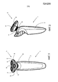
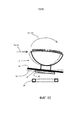
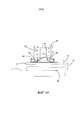
На Фиг. 1 приведен схематичный общий вид устройства персонального ухода, соответствующего настоящему изобретению,In FIG. 1 is a schematic general view of a personal care device in accordance with the present invention,
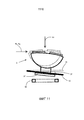
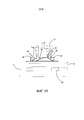
на Фиг. 2 приведен вид сбоку устройства персонального ухода, соответствующего настоящему изобретению,in FIG. 2 is a side view of a personal care device in accordance with the present invention,
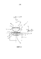
на Фиг. 3 приведено схематичное поперечное сечение первого варианта устройства персонального ухода, которое показано на Фиг. 1 и 2,in FIG. 3 is a schematic cross-sectional view of a first embodiment of a personal care device, which is shown in FIG. 1 and 2,
на Фиг. 4 приведено схематичное поперечное сечение второго варианта устройства персонального ухода, которое показано на Фиг. 1 и 2,in FIG. 4 is a schematic cross-section of a second embodiment of a personal care device, which is shown in FIG. 1 and 2,
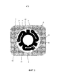
на Фиг. 5 и 6 приведены подробные виды сверху и снизу устройства персонального ухода, которое показано на Фиг. 4,in FIG. 5 and 6 are detailed top and bottom views of the personal care device shown in FIG. four,
на Фиг. 7А и 7В приведены схематичные виды сверху и сбоку датчика устройства персонального ухода, которое показано на Фиг. 4,in FIG. 7A and 7B are schematic top and side views of the sensor of the personal care device shown in FIG. four,
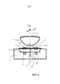
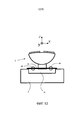
на Фиг. 8 приведено схематичное поперечное сечение третьего варианта устройства персонального ухода, которое показано на Фиг. 1 и 2,in FIG. 8 is a schematic cross-section of a third embodiment of a personal care device, which is shown in FIG. 1 and 2,
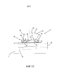
на Фиг. 9 - Фиг. 11 приведены виды устройства персонального ухода, которое показано на Фиг. 8, полученные в результате соответственно осевого смещения, наклона и объединенных осевого смещения и наклона модуля отрезания волос относительно основного корпуса,in FIG. 9 - FIG. 11 shows views of a personal care device as shown in FIG. 8 obtained as a result of axial displacement, tilt, and combined axial displacement and tilt of the hair cutting module with respect to the main body, respectively
на Фиг. 12 приведено схематичное поперечное сечение четвертого варианта устройства персонального ухода, которое показано на Фиг. 1 и 2,in FIG. 12 is a schematic cross-section of a fourth embodiment of a personal care device, which is shown in FIG. 1 and 2,
на Фиг. 13 приведено схематичное поперечное сечение пятого варианта устройства персонального ухода, которое показано на Фиг. 1 и 2, без части отрезания волос,in FIG. 13 is a schematic cross-section of a fifth embodiment of a personal care device, which is shown in FIG. 1 and 2, without part of hair cutting,
на Фиг. 14 приведено схематичное поперечное сечение устройства персонального ухода, которое показано на Фиг. 13, с первой частью отрезания волос,in FIG. 14 is a schematic cross section of a personal care device as shown in FIG. 13, with the first part of hair cutting,
на Фиг. 15 приведено схематичное поперечное сечение устройства персонального ухода, которое показано на Фиг. 13, со второй частью отрезания волос,in FIG. 15 is a schematic cross section of a personal care device as shown in FIG. 13, with a second part of hair cutting,
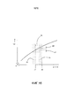
на Фиг. 16 приведен график, на котором показаны рабочие окна датчика устройства персонального ухода, которое показано на Фиг. 13, с первой и второй частями отрезания волос.in FIG. 16 is a graph showing the operating windows of the sensor of the personal care device shown in FIG. 13, with the first and second parts of hair cutting.
На чертежах аналогичные ссылочные номера относятся к аналогичным элементам.In the drawings, like reference numbers refer to like elements.
Подробное описание вариантов реализацииDetailed Description of Embodiments
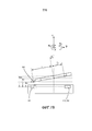
На Фиг. 1 и 2 показано устройство персонального ухода, соответствующее изобретению. Устройство персонального ухода, которое показано на Фиг. 1 и 2, представляет собой бритву 1, содержащую основной корпус 2, который подходит для удерживания пользователем бритвы. На Фиг. 1 для простоты основной корпус 2 показан только схематично с точки зрения того факта, что в пределах объема настоящего изобретения основной корпус 2 может иметь любой подходящий дизайн. На Фиг. 2 показан возможный дизайн основного корпуса 2. Бритва 1 дополнительно содержит модуль 3 отрезания волос, который подходит для контакта с зоной кожи, имеющей отбриваемые волосы, и который может подходящим образом перемещаться относительно этой зоны. Модуль 3 отрезания волос соединен с основным корпусом 2 через центральный вал 4, причем соединение модуля 3 отрезания волос с основным корпусом 2 может быть разъемным. Размеры в поперечном сечении центрального вала 4 значительно меньше размеров в поперечном сечении модуля 3 отрезания волос, и модуль 3 отрезания волос расположен на определенном расстоянии от верхней части 5 основного корпуса 2. Как следствие, соединение между основным корпусом 2 и модулем 3 отрезания волос по внешнему виду является тонким, причем модуль 3 отрезания волос имеет приподнятое положение относительно основного корпуса 2. Из-за этого, когда пользователь выполняет бритье, используя бритву 1, он может иметь чистый вид сбоку модуля 3 отрезания волос.In FIG. 1 and 2 show a personal care device according to the invention. The personal care device shown in FIG. 1 and 2, is a
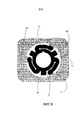
Модуль 3 отрезания волос содержит три режущих блока 6, которые установлены с образованием треугольника. В пределах объема настоящего изобретения число режущих блоков 6 может также быть двумя или больше трех. Для полноты необходимо отметить, что каждый из режущих блоков 6 может быть установлен таким образом, чтобы он мог перемещаться в определенной степени, чтобы облегчить следование каждого из них контуру бреемой зоны кожи. Например, режущие блоки 6 могут поворачиваться, в ограниченной степени, относительно центрального вала 4. Каждый режущий блок 6 содержит внешний режущий элемент 7 в форме чаши, который установлен с верхней стороны режущего блока 6 и который имеет множество отверстий 8 для прохождения отбриваемых волос. Внешний режущий элемент 7 в виде чаши с возможностью поворота соединен с основной частью 9 режущего блока 6. Непосредственно ниже внешнего режущего элемента 7 в виде чаши с внутренней стороны режущего блока 6 с возможностью поворота установлен внутренний режущий элемент (не видим). Во время работы центральная часть внутреннего режущего элемента прижимается к внешнему режущему элементу 7 в виде чаши под действием силы пружины.The
Внутренние режущие элементы режущего блока 6 приводятся в действие, через зубчатые колеса, основной приводной осью, проходящей от мотора в основном корпусе 2 через центральный вал 4 в модуле 3 отрезания волос.The internal cutting elements of the
Описанная бритва 1 на данный момент известна из документа WO 2011055323 А1 и документа WO 200810139 А1, выданных на имя данного заявителя.The described
На Фиг. 3 приведено схематичное поперечное сечение первого варианта бритвы 1. Центральный вал 4 модуля 3 отрезания волос соединен с основным корпусом 2 при помощи пружины 10. Центральный вал 4 проходит параллельно основной оси 11. Основная ось 11 проходит в направлении Z. Из-за пружины 10 модуль 3 отрезания волос может смещаться относительно основного корпуса 2 против силы пружины 10 вдоль основной оси 11. Кроме того, из-за пружины 10 модуль 3 отрезания волос может смещаться относительно основного корпуса 2 против силы пружины 10 в направлениях наклона R1, R2 относительно двух осей 12, 13 наклона. Оси 12, 13 наклона проходят в направлении Х и Y соответственно. Направления Х, Y, Z проходят перпендикулярно друг другу. При смещении модуля 3 отрезания волос относительно основного корпуса 2 центральный вал 4 модуля 3 отрезания волос частично перемещается в пространство 14 основного корпуса 2. Пружина 10 предпочтительно является жесткой вдоль оси Х, вдоль оси Y и в направлении поворота вокруг оси Z.In FIG. 3 shows a schematic cross-section of the first version of the
Бритва 1, соответствующая изобретению, содержит датчик 15, расположенный между основным корпусом 2 и модулем 3 отрезания волос. Датчик 15 содержит первый блок 16 датчика цилиндрической формы, соединенный с основным корпусом 2, и второй блок 17 датчика цилиндрической формы, соединенный с модулем 3 отрезания волос. Блоки 16, 17 датчика расположены симметрично относительно основной оси 11.The
Из-за этой формы блоков 16, 17 датчика каждое положение первого блока 16 датчика относительно основного корпуса 2 находится рядом и напротив положения второго блока 17 датчика относительно модуля 3 отрезания волос. Из-за этой формы блоков 16, 17 датчика первый блок 16 датчика, а также второй блок 17 датчика частично находятся с левой стороны первой плоскости, проходящей через оси Y, Z и частично находятся с правой стороны упомянутой первой плоскости. Первая плоскость проходит перпендикулярно плоскости Фиг. 3. Из-за этой формы блоков 16, 17 датчика первый блок 16 датчика, а также второй блок 17 датчика также частично находятся с передней стороны второй плоскости, проходящей через оси Х, Z, и частично находятся с задней стороны упомянутой второй плоскости. Вторая плоскость проходит параллельно плоскости Фиг. 3.Due to this shape of the sensor blocks 16, 17, each position of the
Внутренние режущие элементы режущих блоков 6 модуля 3 отрезания волос могут поворачиваться относительно внешних режущих элементов 7 в виде чаши вокруг осей 18, 19 вращения относительно внешнего режущего элемента. Третья ось поворота находится за основной осью 11. Три оси поворота расположены симметрично вокруг основной оси 11, причем три оси вращения проходят под углом между 0 градусов и 15 градусами относительно основной оси 11. Во время бритья с использованием бритвы 1 пользователь прижимает режущие блоки 6 к коже с определенной силой, при этом кожа прижимается к модулю 3 отрезания волос с нормальной силой Fn. Из-за упомянутой нормальной силы Fn, проходящей перпендикулярно коже, и сил Fx, Fy, проходящих параллельно коже и вызванных трением между режущими блоками 6 и кожей, когда режущие блоки 6 перемещаются по коже, модуль 3 отрезания волос перемещается против силы пружины 10 в осевом направлении и в направлениях наклона R1, R2.The internal cutting elements of the cutting blocks 6 of the
Датчик 15 измеряет среднее смещение модуля 3 отрезания волос во множестве положений, каждое на фиксированном радиальном расстоянии от основной оси 11. При измерении этого среднего смещения датчик 15 чувствителен только к смещению в направлении Z, в то время как повороты вокруг осей Х и Y исключаются.The
Существует непосредственная связь между силой Fn, из-за которой режущий модуль 3 прижимается против силы пружины 10 относительно основного корпуса 2, и осевым смещением. На основе измеренных смещений и известных свойств жесткости пружины 10 можно вычислить нормальную силу Fn, действующую на кожу, при помощи процессора (не показан). Если осевое смещение и таким образом нормальная сила Fn больше заранее определенной величины, сигнализатором (не показан), находящимся в основном корпусе 2, будет создаваться сигнал предупреждения.There is a direct relationship between the force Fn, due to which the
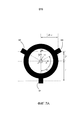
На Фиг. 4 - Фиг. 7В показан второй вариант бритвы 1. Бритва 1 отличается от бритвы, показанной на Фиг. 3, только конфигурацией датчика. Датчик 25 бритвы 1, которая показана на Фиг. 4 - Фиг. 7В, содержит первый бок датчика с, по меньшей мере, тремя блоками Н0, Н1, Н2 в виде датчика Холла, находящимися на регулярных интервалах вокруг основной оси 11 и на одинаковом радиальном расстоянии от основной оси 11. Три блока Н0, Н1, Н2 в виде датчика Холла установлены на расстоянии от пружины 10 на дне 26 пространства 14. Датчик 25 также содержит второй блок датчика с тремя магнитами М0, М1, М2, причем каждый из магнитов М0, М1, М2 находится напротив одного из трех блоков Н0, Н1, Н2 в виде датчика Холла. Три магнита М0, М1, М2 установлены на кольце 27, соединенном с центральным валом 4 модуля 3 отрезания волос. Блоки Н0, Н1 в виде датчика Холла находятся в первом и втором положении рядом и напротив магнитов М0, М1, находящихся в третьем и четвертом положениях, в то время как третий блок Н2 в виде датчика Холла и третий магнит М2 находятся в пятом и шестом положениях, соответственно. Пружина 10 содержит три части 28 пружины, соединенные одним концом с основным корпусом 2 и другим концом с кольцом 27. Через центральное отверстие 29 кольца 27 проходит приводная ось 4' для приведения в действие осей поворота режущих блоков 6. Приводная ось 4' находится внутри центрального вала 4.In FIG. 4 - FIG. 7B shows a second embodiment of the
Если бритва 1 не используется, магниты М0, М1, М2 расположены в плоскости, проходящей параллельно плоскости, в которой расположены блоки Н0, Н1, Н2 в виде датчика Холла.If the
Как можно видеть на Фиг. 7А, магнит М0 и блок Н0 в виде датчика Холла находятся с правой стороны плоскости, проходящей через оси Y, Z, магнит М1 и блок Н1 в виде датчика Холла находятся в плоскости, проходящей через оси Y, Z, в то время как магнит М2 и блок Н2 в виде датчика Холла находятся с левой стороны плоскости, проходящей через оси Y, Z. Кроме того, магниты М0, М2 и блоки Н0, Н2 находятся выше плоскости, проходящей через оси Х, Z, в то время как магнит М1 и блок Н1 в виде датчика Холла находятся ниже плоскости, проходящей через оси X, Z. Из-за упомянутого конкретного положения магнитов М0, М1, М2 и блоков Н0, Н1, Н2 в виде датчика Холла может быть измерено точное смещение модуля 3 отрезания волос в направлениях R1, R2, Z, как будет рассмотрено ниже.As can be seen in FIG. 7A, the magnet M0 and the block H0 in the form of a Hall sensor are located on the right side of the plane passing through the Y, Z axes, the magnet M1 and the block H1 in the form of a Hall sensor are in the plane passing through the axis Y, Z, while the magnet M2 and block H2 in the form of a Hall sensor are located on the left side of the plane passing through the axis Y, Z. In addition, magnets M0, M2 and blocks Н0, Н2 are located above the plane passing through the axis X, Z, while the magnet M1 and block H1 in the form of a Hall sensor are located below the plane passing through the axes X, Z. Due to the aforementioned specific position of the magneto in M0, M1, M2 and blocks Н0, Н1, Н2 in the form of a Hall sensor, the exact displacement of the
Магниты М0, М1, М2 и блоки Н0, Н1, Н2 в виде датчика Холла находятся под углом 120 градусов относительно друг друга.Magnets M0, M1, M2 and blocks Н0, Н1, Н2 in the form of a Hall sensor are at an angle of 120 degrees relative to each other.
При каждой комбинации одного из магнитов М0, М1, М2 и одного из блоков Н0, Н1, Н2 в виде датчика Холла измеряются расстояния между первым и третьим положением, вторым и четвертым положением и пятым и шестым положением. Измеренное расстояние между третьим положением магнита М0 и первым положением блока Н0 в виде датчика Холла представляет собой h0, измеренное расстояние между четвертым положением магнита М1 и вторым положением блока Н1 в виде датчика Холла представляет собой h1 и измеренное расстояние между шестым положением магнита М2 и пятым положением блока Н2 в виде датчика Холла представляет собой h2.For each combination of one of the magnets M0, M1, M2 and one of the blocks Н0, Н1, Н2 in the form of a Hall sensor, the distances between the first and third positions, the second and fourth positions, and the fifth and sixth positions are measured. The measured distance between the third position of the magnet M0 and the first position of the Hall block in the form of a Hall sensor is h0, the measured distance between the fourth position of the magnet M1 and the second position of the block H1 in the form of a Hall sensor is h1 and the measured distance between the sixth position of the magnet M2 and the fifth position block H2 in the form of a Hall sensor is h2.
На основе измеренных расстояний h0, h1, h2, радиуса r и угла 120 градусов может быть вычислено смещение Pz центра С модуля 3 отрезания волос следующим образом:Based on the measured distances h0, h1, h2, radius r and angle 120 degrees, the offset Pz of the center C of the
h02=(h0+h2)/2; среднее расстояние магнитов М0 и М2 до блоков Н0 и Н2 в виде датчика Холлаh02 = (h0 + h2) / 2; the average distance of the magnets M0 and M2 to the blocks Н0 and Н2 in the form of a Hall sensor
Pz=(h0+h1+h2)/3Pz = (h0 + h1 + h2) / 3
ΘX=arcsin((Pz-h1)/r)ΘX = arcsin ((Pz-h1) / r)
ΘY=arcsin(h2-h0)/(r*![]()
![]()
Свойства жесткости пружины 10 известны, в результате чего на основе известных свойств cz жесткости пружины 10 и значения Pz смещения может быть вычислена нормальная сила Fn Fn=cz* Pz.The stiffness properties of the
Если нормальная сила Fn больше заранее определенной величины, будет выдан предупреждающий сигнал.If the normal force Fn is greater than a predetermined value, a warning signal will be issued.
Таким же образом на основе известных свойств cx, cy жесткости пружины 10 против вращения вокруг оси х и оси y, соответственно, могут быть вычислены силы Fx и Fy Fx=cx* ΘX и Fy=cy* ΘY. Если силы Fx, Fy больше заранее определенной величины, будет выдан другой сигнал предупреждения. В таком случае пользователю будет посоветовано использовать гель для уменьшения сил трения Fx, Fy.In the same way, on the basis of the known properties cx, cy of the stiffness of the
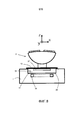
На Фиг. 8 - Фиг. 11 показан третий вариант бритвы 1. Бритва 1 отличается от бритв, показанных на Фиг. 3 и Фиг. 4 - Фиг. 7В, только конфигурацией датчика. Датчик 35 бритвы, которая показана на Фиг. 8 - Фиг. 11, содержит первый блок датчика с катушкой 36 кольцевой формы, расположенный симметрично относительно основной оси 1. Катушка 36 кольцевой формы установлена на расстоянии от пружины 10 на дне 26 пространства 14. Датчик 35 также содержит второй блок датчика с металлической пластиной 37 в форме кольца, расположенный симметрично относительно основной оси 11. Металлическая пластина функционирует как коротко замкнутая катушка только с одной обмоткой. Металлическая пластина 37 в форме кольца соединена с центральным валом 4 модуля 3 отрезания волос.In FIG. 8 - FIG. 11 shows a third embodiment of the
Перемещение металлической пластины 37 относительно катушки 36 влияет на индуктивность катушки 36.The movement of the
Если модуль 3 отрезания волос только смещается вдоль основной оси 11, как показано на Фиг. 9, модуль 3 отрезания волос перемещается из положения, которое показано пунктирными линиями, в положение, показанное сплошными линиями. По всей периферии катушки частичный вклад в индуктивность катушки будет меняться таким же образом. Изменение в индуктивности катушки 36 является мерой смещения модуля 3 отрезания волос и, таким образом, силы Fn.If the
Если модуль 3 отрезания волос только наклоняется относительно оси, проходящей перпендикулярно основной оси 11, как показано на Фиг. 10, модуль 3 отрезания волос перемещается из положения, которое показано пунктирными линиями, в положение, показанное сплошными линиями. С левой стороны Фиг. 10 расстояние между катушкой 36 и пластиной 37 будет увеличиваться, в то время как с правой стороны Фиг. 10 расстояние между катушкой 36 и пластиной 37 будет уменьшаться. Однако среднее расстояние между катушкой 36 и пластиной 37 будет оставаться тем же самым, в результате чего индуктивность катушки 36 не будет меняться.If the
Если модуль 3 отрезания волос смещается вдоль основной оси 11, а также наклоняется относительно оси, проходящей перпендикулярно основной оси, как показано на Фиг. 11, модуль 3 отрезания волос перемещается из положения, показанного пунктирными линиями, в положение, показанное сплошными линиями.If the
Изменение индуктивности катушки 36 будет обусловлено только смещением вдоль основной оси 11.The change in the inductance of the
Также можно использовать пластину из электроизоляционного материала с высокой магнитной проницаемостью. Таким образом, пластина может быть изготовлена из феррита. Такая пластина также будет влиять на индуктивность катушки 36.You can also use a plate of electrical insulation material with high magnetic permeability. Thus, the plate can be made of ferrite. Such a plate will also affect the inductance of the
Датчики, описанные выше, имеют следующие преимущества:The sensors described above have the following advantages:
- датчик имеет очень низкую стоимость;- the sensor has a very low cost;
- датчик может быть помещен внутри бритвы, в результате чего нет необходимости в проводах вовне бритвы. Это улучшает водонепроницаемость бритвы;- the sensor can be placed inside the razor, as a result of which there is no need for wires outside the razor. This improves the watertightness of the razor;
- датчик может измерять статические смещения, так как он имеет низкий дрейф по времени;- the sensor can measure static displacements, since it has a low drift in time;
- датчик имеет очень большой срок службы, так как он не соединен механически и, следовательно, свободен от износа.- the sensor has a very long service life, as it is not mechanically connected and, therefore, free from wear.
На Фиг. 12 показан четвертый вариант бритвы 1. Бритва 1 отличается от бритв, показанных на Фиг. 3, 4-7В и 8-11, только конфигурацией датчика. Датчик 45 подходит для измерения среднего смещения Pz модуля 3 отрезания волос вдоль основной оси 11, причем датчик находится на расстоянии от основной оси 11, чтобы имелась возможность прохождения приводной оси, используемой для приведения в действие осей вращения режущих блоков, по центру через датчик. Такой датчик 45 может содержать, например, пьезоэлементы, резисторы, чувствительные к силе, емкостные датчики расстояния или тензометрические датчики.In FIG. 12 shows a fourth embodiment of the
Также возможно, чтобы магниты М0, М1, М2 были соединены с основным корпусом, а блоки Н0, Н1, Н2 в виде датчиков Холла были соединены с модулем 3 отрезания волос.It is also possible that the magnets M0, M1, M2 are connected to the main body, and the blocks H0, H1, H2 in the form of Hall sensors are connected to the
Также возможно, чтобы модуль 3 отрезания волос имел возможность только наклоняться относительно одной единственной оси наклона.It is also possible that the
На Фиг. 13 - Фиг. 15 показан пятый вариант устройства 51 персонального ухода, соответствующего изобретению. Устройство персонального ухода отличается от бритвы 1, показанной на Фиг. 8 - Фиг. 11, конфигурацией модуля 3 отрезания волос. Как и в бритве 1, которая показана на Фиг. 8 - Фиг. 11, датчик 35 устройства 51 персонального ухода содержит первый блок датчика с катушкой 36 в форме кольца, расположенный симметрично относительно основной оси 11. Датчик 35 также содержит второй блок датчика с металлической пластиной 37 в форме кольца, расположенный симметрично относительно основной оси 11. Металлическая пластина функционирует как короткозамкнутая катушка только с одной обмоткой. Перемещение металлической пластины 37 относительно катушки 36 влияет на индуктивность катушки 36. В положении, показанном на Фиг. 13, металлическая пластина 37 находится на расстоянии d0 от катушки 36. Устройство 51 персонального ухода отличается от бритвы 1, которая показана на Фиг. 8 - Фиг. 11, тем, что модуль 3 отрезания волос содержит промежуточную часть 52 с трубчатым корпусом, центральное отверстие 54 в корпусе 53 и элемент 55, способный удерживать часть 56, 57 отрезания волос в отверстии 54. Промежуточная часть 52 также содержит ряд первых пружин 58. Каждая пружина 58 содержит проходящую горизонтально часть 59, соединенную с металлической пластиной 37, наклонную часть 60, соединенную с проходящей горизонтально частью 59, и проходящую вертикально часть 61, соединенную с наклонной частью 60. Проходящая вертикально часть 61 может скользить в направлении, параллельном основной оси 11, относительно корпуса 53. Промежуточная часть 52 также содержит ряд вторых пружин 62, соединенных одним концом 63 с трубчатым корпусом 53 и другим концом 64 с металлической пластиной 37. Вторые пружины 62 тянут металлическую пластину 37 от трубчатого корпуса 53. Совокупная жесткость вторых пружин 62 меньше совокупной жесткости первых пружин 58. Кроме того, промежуточная часть 52 содержит стопорные элементы 65 в форме крюка, ограничивающие перемещение металлической пластины 37 в направлении от трубчатого корпуса 53.In FIG. 13 - FIG. 15 shows a fifth embodiment of the
На Фиг. 14 показано устройство 51 персонального ухода с первой частью 56 отрезания волос, с возможностью снятия соединенной с промежуточной частью 52. Первая часть 56 отрезания волос может содержать основной участок 9 и режущие блоки 6 (на Фиг. 14 не показаны), как и бритва 1, которая показана на Фиг. 1 и 2. Часть 56 отрезания волос содержит трубчатую часть 66, имеющую концевой участок 67. Когда трубчатая часть 66 первой части 56 отрезания волос вставляется в отверстие 54 промежуточной части 52, она удерживается в этом положении при помощи элемента 55. Элемент 55 может содержать пружину, способную крепко удерживать трубчатую часть 62, но позволяющую снимать первую часть 56 отрезания волос, когда пользователь крепко тянет первую часть 56 отрезания волос. Такое соединение известно в устройствах персонального ухода и не будет далее рассмотрено. Когда трубчатая часть 62 первой части 56 отрезания волос вставляется в отверстие 54 промежуточной части 52, концевой участок 67 будет прижиматься к проходящим вертикально частям 61 пружин 58, из-за этих сил проходящие вертикально части 61 пружин 58 будут перемещаться в направлении, параллельном основной оси 11, и будут перемещать металлическою пластину 37 к катушке 36 на расстояние ds. Это положение металлической пластины 37 является первым эталонным положением, и когда устройство 51 персонального ухода используется, металлическая пластина 37 будет перемещаться дальше к катушке 36, когда режущие блоки 6 прижимаются к коже пользователя.In FIG. 14 shows a
На Фиг. 15 показано устройство 51 персонального ухода со второй частью 57 отрезания волос, с возможностью снятия соединенной с промежуточной частью 52. Вторая часть 57 отрезания волос может содержать триммер или щетку (на Фиг. 15 не показаны). Часть 57 отрезания волос содержит трубчатую часть 68, имеющую концевой участок 69. Трубчатая часть 68 второй части 57 отрезания волос соединена с промежуточной частью 52 таким же образом, что и трубчатая часть 66 первой части 56 отрезания волос. Однако когда трубчатая часть 68 второй части 57 отрезания волос вставляется в отверстие 54 промежуточной части 52, концевой участок 69 будет находиться на расстоянии d2 от проходящих вертикально частей 61 пружин 58 и не будет прижиматься к вертикально проходящим частям 61 пружины 58. Расстояние d2 между металлической пластиной 37 и катушкой 36 является тем же самым, что и расстояние d0 на Фиг. 13, причем с промежуточной частью 52 не соединена часть отрезания волос. Это положение металлической пластины 37 является вторым эталонным положением, и когда устройство 51 персонального ухода используется, металлическая пластина 37 будет перемещаться дальше к катушке 36, когда устройство персонального ухода прижимается к коже пользователя.In FIG. 15 shows a
На Фиг. 16 приведен график, на котором по оси х отложено расстояние d между металлической пластиной 37 и катушкой 36, а по оси y отложено соответствующее значение индуктивности. На этом графике первое эталонное положение находится на расстоянии d1, которое меньше расстояния d2 второго эталонного положения. Когда устройство 51 персонального ухода используется, расстояние d будет меняться в серой зоне 70, 71, соответственно.In FIG. 16 is a graph in which the x-axis represents the distance d between the
Соответствующие значения индуктивности будут меняться в рабочих окнах W1, W2 соответственно.The corresponding inductance values will change in the working windows W1, W2, respectively.
Путем измерения индуктивности можно определить, соединены ли первая или вторая части 56, 57 отрезания волос с промежуточной частью 52.By measuring the inductance, it can be determined whether the first or second
То же изменение в рабочем окне может также быть достигнуто при помощи смещения электрического сопротивления металлической пластины 37, например, при помощи варианта, в котором металлическая пластина 37 имеет паз, который замыкается накоротко, когда устанавливается первая часть отрезания волос с бреющим блоком. Принцип изменения рабочего окна датчика 35 может также быть применен на других принципах распознавания силы, например, датчик Холла, тензометрический датчик или датчики силы на пьезооснове.The same change in the working window can also be achieved by shifting the electrical resistance of the
Устройство персонального ухода может также представлять собой вибрационную бритву, триммер, устройство ухода за внешностью или другой тип режущего устройства.The personal care device may also be a vibrating razor, trimmer, exterior care device, or other type of cutting device.
Первое, второе, третье и четвертое положения могут также находиться на той же стороне плоскости, проходящей через основную ось и ось наклона, если расстояние от первого положения до плоскости отличается от расстояния от второго положения до плоскости. Главной особенностью является то, что изменение расстояния из-за наклона отличается между первым и третьим положениями и между вторым и четвертым положениями.The first, second, third and fourth positions may also be on the same side of the plane passing through the main axis and the tilt axis, if the distance from the first position to the plane is different from the distance from the second position to the plane. The main feature is that the change in distance due to the slope differs between the first and third positions and between the second and fourth positions.
Специалист в данной области техники поймет, что настоящее изобретение никоим образом не ограничивается предпочтительными вариантами. При реализации заявляемого изобретения на практике специалистами в данной области техники могут быть поняты и осуществлены другие изменения в описанные варианты, на основе изучения чертежей, описания и приложенной Формулы изобретения.One skilled in the art will understand that the present invention is in no way limited to the preferred embodiments. When implementing the claimed invention in practice, specialists in the art can understand and make other changes to the described options, based on the study of the drawings, description and appended claims.
В пунктах Формулы изобретения слово "содержащий" не исключает других элементов или этапов, а упоминание в единственном числе не исключает множества. Простой факт того, что определенные критерии указаны в не зависящих друг от друга зависимых пунктах не указывает на то, что с выгодой не может быть использована комбинация этих критериев.In the claims, the word “comprising” does not exclude other elements or steps, and singular reference does not exclude a plurality. The simple fact that certain criteria are indicated in independent dependent clauses does not indicate that a combination of these criteria cannot be used to advantage.
Любые ссылочные обозначения в пунктах Формулы изобретения не должны восприниматься как ограничивающие объем пунктов.Any reference signs in the claims should not be construed as limiting the scope of the paragraphs.
Список ссылочных обозначенийReference List
1 бритва1 razor
2 основной корпус2 main building
3 модуль отрезания волос3 hair cutting module
4 центральный вал4 central shaft
4' приводная ось4 'drive axle
5 верхняя часть5 top
6 режущий блок6 cutting unit
7 внешний режущий элемент7 external cutting element
8 отверстие8 hole
9 основная часть9 main part
10 пружина10 spring
11 основная ось11 main axis
12 ось наклона12 tilt axis
13 ось наклона13 tilt axis
14 пространство14 space
15 датчик15 sensor
16 первый блок датчика16 first sensor unit
17 второй блок датчика17 second sensor unit
18 ось вращения18 axis of rotation
19 ось вращения19 axis of rotation
25 датчик25 sensor
26 дно26 bottom
27 кольцо27 ring
28 часть пружины28 spring part
29 центральное отверстие29 center hole
35 датчик35 sensor
36 катушка36 coil
37 металлическая пластина37 metal plate
45 датчик45 sensor
51 устройство персонального ухода51 personal care devices
52 промежуточная часть52 intermediate
53 трубчатый корпус53 tubular body
54 центральное отверстие54 center hole
55 элемент55 element
56 часть отрезания волос56 piece of hair cutting
57 часть отрезания волос57 piece of hair cutting
58 первая пружина58 first spring
59 проходящая горизонтально часть59 horizontal section
60 наклонная часть60 inclined part
61 проходящая вертикально часть61 vertically extending part
62 вторая пружина62 second spring
63 конец63 end
64 конец64 end
65 трубчатая часть65 tubular part
66 трубчатая часть66 tubular part
67 концевой участок67 end section
68 трубчатая часть68 tubular part
69 концевой участок69 end section
70 серая зона70 gray zone
71 серая зона71 gray zone
С центрC center
Fn сила FnFn force fn
Н0 блок в виде датчика ХоллаH0 block in the form of a Hall sensor
Н1 блок в виде датчика ХоллаH1 block in the form of a Hall sensor
Н2 блок в виде датчика ХоллаH2 block in the form of a Hall sensor
М0 магнитM0 magnet
М1 магнитM1 magnet
М2 магнитM2 magnet
Pz смещениеPz offset
R радиусR radius
R1 направление R1 наклона R1 tilt direction R1
R2 направление R2 наклона R2 tilt direction R2
W1 рабочее окноW1 working window
W2 рабочее окноW2 working window
Z направлениеZ direction
δ расстояниеδ distance
Claims (13)
Applications Claiming Priority (3)
| Application Number | Priority Date | Filing Date | Title |
|---|---|---|---|
| EP13191490.5 | 2013-11-05 | ||
| EP13191490 | 2013-11-05 | ||
| PCT/EP2014/072931 WO2015025064A1 (en) | 2013-11-05 | 2014-10-27 | A personal care device |
Publications (3)
| Publication Number | Publication Date |
|---|---|
| RU2015121422A RU2015121422A (en) | 2016-12-27 |
| RU2015121422A3 RU2015121422A3 (en) | 2018-06-08 |
| RU2674792C2 true RU2674792C2 (en) | 2018-12-13 |
Family
ID=49517385
Family Applications (1)
| Application Number | Title | Priority Date | Filing Date |
|---|---|---|---|
| RU2015121422A RU2674792C2 (en) | 2013-11-05 | 2014-10-27 | Personal care device |
Country Status (7)
| Country | Link |
|---|---|
| US (1) | US9919437B2 (en) |
| EP (1) | EP2888086B1 (en) |
| JP (1) | JP5977460B2 (en) |
| CN (1) | CN104768718B (en) |
| BR (1) | BR112015008478B1 (en) |
| RU (1) | RU2674792C2 (en) |
| WO (1) | WO2015025064A1 (en) |
Families Citing this family (39)
| Publication number | Priority date | Publication date | Assignee | Title |
|---|---|---|---|---|
| CN102348544B (en) * | 2009-03-09 | 2014-12-03 | 皇家飞利浦电子股份有限公司 | Shaving device with improved contour following |
| JP6506261B2 (en) * | 2013-05-30 | 2019-04-24 | コーニンクレッカ フィリップス エヌ ヴェKoninklijke Philips N.V. | Device and system for treating hair and / or skin |
| JP6509334B2 (en) * | 2014-10-07 | 2019-05-08 | コーニンクレッカ フィリップス エヌ ヴェKoninklijke Philips N.V. | Appliance for performing cutting action on hair present in the area of skin |
| AU361922S (en) * | 2014-10-24 | 2015-05-21 | Koninklijke Philips Nv | Shaver without shaving head |
| AU361921S (en) * | 2014-10-24 | 2015-05-21 | Koninklijke Philips Nv | Shaving head |
| CL2015001001S1 (en) * | 2014-10-24 | 2015-08-07 | Koninkl Philips Nv | Electric shaver |
| EP3103601A1 (en) * | 2015-06-08 | 2016-12-14 | BaByliss Faco sprl | Beard trimmer with swing mounted cutting system |
| USD808077S1 (en) * | 2015-08-17 | 2018-01-16 | Koninklijke Philips N.V. | Three head dry shaver |
| US10383486B2 (en) * | 2015-10-29 | 2019-08-20 | Thomas Nichols | Handheld motorized facial brush having three floating heads |
| EP3354425B1 (en) * | 2017-01-26 | 2020-07-29 | Braun GmbH | Shaver with light source |
| CN106671146B (en) * | 2017-02-14 | 2018-08-17 | 广东罗曼智能科技股份有限公司 | Detachable floating shaver |
| EP3401065A1 (en) * | 2017-05-11 | 2018-11-14 | Koninklijke Philips N.V. | Method and apparatus for providing feedback regarding motion of a rotary shaver performed by a user |
| EP3450120B1 (en) * | 2017-08-30 | 2021-12-15 | Braun GmbH | Personal care device |
| USD889042S1 (en) * | 2018-02-27 | 2020-06-30 | Koninklijke Philips N.V. | Handle for a shaver |
| USD912902S1 (en) * | 2018-02-27 | 2021-03-09 | Koninkiijke Phillips N.V. | Shaver |
| EP3546148B1 (en) * | 2018-03-27 | 2022-01-12 | Braun GmbH | Personal care device |
| USD884972S1 (en) * | 2018-04-12 | 2020-05-19 | Koninklijke Philips N.V. | Shaver |
| USD880064S1 (en) * | 2018-05-04 | 2020-03-31 | Koninklijke Philips N.V. | Shaver |
| CN108714916A (en) * | 2018-06-29 | 2018-10-30 | 蔡华杰 | A kind of electric shaver |
| EP3867025B1 (en) * | 2018-10-19 | 2025-03-05 | The Gillette Company LLC | Grooming device |
| CN109968412B (en) * | 2019-03-07 | 2024-04-23 | 深圳素士科技股份有限公司 | Blade head floating structure and personal care device |
| EP3725473A1 (en) | 2019-04-18 | 2020-10-21 | Koninklijke Philips N.V. | Pressure sensing electric shaver |
| US12240134B2 (en) | 2019-07-01 | 2025-03-04 | Spectrum Brands, Inc. | Electric grooming device |
| EP3769921A1 (en) * | 2019-07-24 | 2021-01-27 | Koninklijke Philips N.V. | Providing feedback to a user of a shaving device during a shaving operation |
| EP3769644A1 (en) * | 2019-07-25 | 2021-01-27 | Koninklijke Philips N.V. | Skin treatment device and method of controlling a skin treatment device |
| USD955642S1 (en) * | 2019-08-06 | 2022-06-21 | Koninklijke Philips N.V. | Shaver |
| USD949479S1 (en) * | 2019-08-21 | 2022-04-19 | Koninklijke Philips N.V. | Handle for shaver |
| USD970112S1 (en) * | 2019-08-26 | 2022-11-15 | Koninklijke Philips N.V. | Handle for shaver |
| USD963246S1 (en) * | 2019-08-29 | 2022-09-06 | Koninklijke Philips N.V. | Head for shaver |
| USD932700S1 (en) * | 2020-02-27 | 2021-10-05 | Koninklijke Philips N.V. | Shaver |
| USD963247S1 (en) * | 2020-02-27 | 2022-09-06 | Koninklijke Philips N.V. | Cutting unit for shaver |
| EP3800644A1 (en) * | 2019-10-02 | 2021-04-07 | Koninklijke Philips N.V. | Determining a location of a device |
| EP3831555A1 (en) | 2019-12-04 | 2021-06-09 | Koninklijke Philips N.V. | A shaver head for an electric shaver |
| EP3842194A1 (en) * | 2019-12-24 | 2021-06-30 | Koninklijke Philips N.V. | Shaving unit having hair-cutting units with first and second pivot axes |
| USD999452S1 (en) * | 2020-01-16 | 2023-09-19 | Koninklijke Philips.N.V. | Shaver |
| USD932697S1 (en) * | 2020-02-05 | 2021-10-05 | Koninklijke Philips N.V. | Handle for shaver |
| USD963943S1 (en) * | 2020-02-28 | 2022-09-13 | Koninklijke Philips N.V. | Head for shaver |
| USD980529S1 (en) * | 2022-01-04 | 2023-03-07 | Feng Li | Shaver |
| CN115229851B (en) * | 2022-07-21 | 2024-09-24 | 深圳素士科技股份有限公司 | Electric shaver |
Citations (4)
| Publication number | Priority date | Publication date | Assignee | Title |
|---|---|---|---|---|
| DE19601780C1 (en) * | 1996-01-19 | 1997-06-26 | Braun Ag | Electric shaver with indicator of maximum deflection of cutting head |
| US20070256302A1 (en) * | 2006-05-08 | 2007-11-08 | Izumi Products Company | Rotary electric shaver |
| US20100018058A1 (en) * | 2004-12-22 | 2010-01-28 | Koninklijke Philips Electronics N.V. | Shaving apparatus |
| RU2010105126A (en) * | 2007-09-17 | 2011-10-27 | Дзе Жиллетт Компани (Us) | CARTRIDGE DISCONNECT SENSOR |
Family Cites Families (30)
| Publication number | Priority date | Publication date | Assignee | Title |
|---|---|---|---|---|
| JPS59184778U (en) * | 1983-05-25 | 1984-12-08 | フイリツプス工業振興株式会社 | automatic operating electric shaver |
| DE3843936C1 (en) * | 1988-12-24 | 1990-05-31 | Braun Ag, 6000 Frankfurt, De | |
| DE4244164C2 (en) * | 1992-12-24 | 1995-09-07 | Braun Ag | Dry shaver with a pivoting long hair trimmer |
| CA2168572A1 (en) * | 1994-06-01 | 1995-12-07 | Jan De Boer | Shaving apparatus with electrically adjustable cutting unit |
| JP3682997B2 (en) | 1995-01-11 | 2005-08-17 | 株式会社泉精器製作所 | Electric razor |
| EP0888205B1 (en) * | 1996-12-20 | 2002-11-13 | Koninklijke Philips Electronics N.V. | Shaving apparatus |
| US6009623A (en) * | 1997-10-02 | 2000-01-04 | Warner-Lambert Company | Razor with in situ sensor |
| ATE472395T1 (en) * | 2001-07-30 | 2010-07-15 | Koninkl Philips Electronics Nv | COUPLING FOR INNER CUTTING ELEMENT OF A ROTARY SHAVER |
| US8061040B2 (en) * | 2002-02-01 | 2011-11-22 | Patrick Joseph Walls | Cutter blade assembly and dry shaver for variable height of cut |
| US20040098862A1 (en) * | 2002-08-21 | 2004-05-27 | Eveready Battery Company, Inc. | Razor system having razor sensors |
| US8627573B2 (en) * | 2002-10-05 | 2014-01-14 | Braun Gmbh | Hair-removing device |
| JP4490219B2 (en) * | 2004-09-21 | 2010-06-23 | 株式会社泉精器製作所 | Rotary electric razor |
| DE602005019321D1 (en) * | 2004-11-29 | 2010-03-25 | Koninkl Philips Electronics Nv | RAZOR WITH HINGE BETWEEN THE HOUSING AND SCISSOR |
| US8844141B2 (en) * | 2004-12-22 | 2014-09-30 | Koninklijke Philips N.V. | Rotary shavers, with improved drive and support structure for the shaving heads |
| JP4919255B2 (en) * | 2005-10-25 | 2012-04-18 | 株式会社泉精器製作所 | Rotary electric razor |
| JP2007151925A (en) * | 2005-12-07 | 2007-06-21 | Izumi Products Co | Rotary electric razor |
| DE102006004675A1 (en) * | 2006-02-02 | 2007-08-09 | Braun Gmbh | Electric razor |
| JP2007319339A (en) * | 2006-05-31 | 2007-12-13 | Izumi Products Co | Rotary type electric shaver |
| JP5215301B2 (en) | 2006-07-14 | 2013-06-19 | コーニンクレッカ フィリップス エレクトロニクス エヌ ヴィ | Shaver with space for collecting hair to be excised |
| US20080034591A1 (en) * | 2006-08-08 | 2008-02-14 | Kam Fai Fung | Shaver with swivel head |
| US8261452B2 (en) * | 2006-11-20 | 2012-09-11 | Koninklijke Philips Electronics N.V. | Rotary shaver with improved support structure for shaving heads |
| JP4265666B2 (en) * | 2007-02-23 | 2009-05-20 | パナソニック電工株式会社 | Hair removal equipment |
| EP2296850B1 (en) * | 2008-05-27 | 2012-09-26 | Koninklijke Philips Electronics N.V. | Domestic appliance comprising means for generating electric energy in a functional action unit |
| JP5339338B2 (en) * | 2008-06-27 | 2013-11-13 | 株式会社泉精器製作所 | Rotary electric razor |
| CN102348544B (en) * | 2009-03-09 | 2014-12-03 | 皇家飞利浦电子股份有限公司 | Shaving device with improved contour following |
| US9027251B2 (en) * | 2009-04-29 | 2015-05-12 | Spectrum Brands, Inc. | Rotary electric shaver |
| JP5473462B2 (en) * | 2009-08-06 | 2014-04-16 | 株式会社泉精器製作所 | Rotary electric razor |
| RU2548347C2 (en) | 2009-11-09 | 2015-04-20 | Конинклейке Филипс Электроникс Н.В. | Shaving head unit and razor with such shaving head unit |
| US20120159795A1 (en) * | 2010-12-27 | 2012-06-28 | Walmsley Harry A | Electric head shaver with ergonomic handle |
| US9386843B2 (en) * | 2014-08-05 | 2016-07-12 | L'oreal | Adjusting brushhead for facial contours |
-
2014
- 2014-10-27 RU RU2015121422A patent/RU2674792C2/en active
- 2014-10-27 JP JP2015547094A patent/JP5977460B2/en active Active
- 2014-10-27 CN CN201480002588.2A patent/CN104768718B/en active Active
- 2014-10-27 EP EP14789283.0A patent/EP2888086B1/en active Active
- 2014-10-27 BR BR112015008478-8A patent/BR112015008478B1/en not_active IP Right Cessation
- 2014-10-27 WO PCT/EP2014/072931 patent/WO2015025064A1/en not_active Ceased
- 2014-10-27 US US14/428,994 patent/US9919437B2/en active Active
Patent Citations (4)
| Publication number | Priority date | Publication date | Assignee | Title |
|---|---|---|---|---|
| DE19601780C1 (en) * | 1996-01-19 | 1997-06-26 | Braun Ag | Electric shaver with indicator of maximum deflection of cutting head |
| US20100018058A1 (en) * | 2004-12-22 | 2010-01-28 | Koninklijke Philips Electronics N.V. | Shaving apparatus |
| US20070256302A1 (en) * | 2006-05-08 | 2007-11-08 | Izumi Products Company | Rotary electric shaver |
| RU2010105126A (en) * | 2007-09-17 | 2011-10-27 | Дзе Жиллетт Компани (Us) | CARTRIDGE DISCONNECT SENSOR |
Also Published As
| Publication number | Publication date |
|---|---|
| RU2015121422A3 (en) | 2018-06-08 |
| WO2015025064A1 (en) | 2015-02-26 |
| JP2015536778A (en) | 2015-12-24 |
| EP2888086A1 (en) | 2015-07-01 |
| US20160236360A1 (en) | 2016-08-18 |
| EP2888086B1 (en) | 2016-03-16 |
| CN104768718B (en) | 2016-09-21 |
| BR112015008478A2 (en) | 2017-07-04 |
| BR112015008478B1 (en) | 2020-11-03 |
| CN104768718A (en) | 2015-07-08 |
| US9919437B2 (en) | 2018-03-20 |
| RU2015121422A (en) | 2016-12-27 |
| JP5977460B2 (en) | 2016-08-24 |
Similar Documents
| Publication | Publication Date | Title |
|---|---|---|
| RU2674792C2 (en) | Personal care device | |
| EP3852983B1 (en) | Pressure sensing electric shaver | |
| JP4446131B2 (en) | Razor device and razor head and razor handle | |
| JP6901051B1 (en) | Rolling tools, modules and cutting systems | |
| CN104422354B (en) | Confirm the method for the workpiece measurement in dimensional measurement hand tools | |
| JP2010515515A (en) | Razor cartridge measuring device | |
| CN104602874B (en) | Electric razor | |
| EP4175799B1 (en) | Grooming device with eject button displacement | |
| EP4175801B1 (en) | Grooming device having an eject sensor | |
| EP2015020B1 (en) | Texture measuring apparatus and method | |
| JP6509334B2 (en) | Appliance for performing cutting action on hair present in the area of skin | |
| US20240083050A1 (en) | Shaving system | |
| CN110375938B (en) | Device and method for measuring dynamic rigidity of headstock of cylindrical grinding machine | |
| US6715368B1 (en) | Rotation sensor | |
| EP4427893A1 (en) | Personal care apparatus | |
| JP2983810B2 (en) | Constant pressure measuring machine | |
| BE1022667B1 (en) | Pressure sensor | |
| JP2000093666A (en) | Electric shaver |