EP2708770A1 - Disk brake device - Google Patents
Disk brake device Download PDFInfo
- Publication number
- EP2708770A1 EP2708770A1 EP12781993.6A EP12781993A EP2708770A1 EP 2708770 A1 EP2708770 A1 EP 2708770A1 EP 12781993 A EP12781993 A EP 12781993A EP 2708770 A1 EP2708770 A1 EP 2708770A1
- Authority
- EP
- European Patent Office
- Prior art keywords
- braking
- braking surface
- slide
- rotor
- electric motor
- Prior art date
- Legal status (The legal status is an assumption and is not a legal conclusion. Google has not performed a legal analysis and makes no representation as to the accuracy of the status listed.)
- Withdrawn
Links
Images


Classifications
-
- F—MECHANICAL ENGINEERING; LIGHTING; HEATING; WEAPONS; BLASTING
- F16—ENGINEERING ELEMENTS AND UNITS; GENERAL MEASURES FOR PRODUCING AND MAINTAINING EFFECTIVE FUNCTIONING OF MACHINES OR INSTALLATIONS; THERMAL INSULATION IN GENERAL
- F16D—COUPLINGS FOR TRANSMITTING ROTATION; CLUTCHES; BRAKES
- F16D55/00—Brakes with substantially-radial braking surfaces pressed together in axial direction, e.g. disc brakes
- F16D55/02—Brakes with substantially-radial braking surfaces pressed together in axial direction, e.g. disc brakes with axially-movable discs or pads pressed against axially-located rotating members
- F16D55/22—Brakes with substantially-radial braking surfaces pressed together in axial direction, e.g. disc brakes with axially-movable discs or pads pressed against axially-located rotating members by clamping an axially-located rotating disc between movable braking members, e.g. movable brake discs or brake pads
- F16D55/224—Brakes with substantially-radial braking surfaces pressed together in axial direction, e.g. disc brakes with axially-movable discs or pads pressed against axially-located rotating members by clamping an axially-located rotating disc between movable braking members, e.g. movable brake discs or brake pads with a common actuating member for the braking members
- F16D55/225—Brakes with substantially-radial braking surfaces pressed together in axial direction, e.g. disc brakes with axially-movable discs or pads pressed against axially-located rotating members by clamping an axially-located rotating disc between movable braking members, e.g. movable brake discs or brake pads with a common actuating member for the braking members the braking members being brake pads
- F16D55/226—Brakes with substantially-radial braking surfaces pressed together in axial direction, e.g. disc brakes with axially-movable discs or pads pressed against axially-located rotating members by clamping an axially-located rotating disc between movable braking members, e.g. movable brake discs or brake pads with a common actuating member for the braking members the braking members being brake pads in which the common actuating member is moved axially, e.g. floating caliper disc brakes
- F16D55/2262—Brakes with substantially-radial braking surfaces pressed together in axial direction, e.g. disc brakes with axially-movable discs or pads pressed against axially-located rotating members by clamping an axially-located rotating disc between movable braking members, e.g. movable brake discs or brake pads with a common actuating member for the braking members the braking members being brake pads in which the common actuating member is moved axially, e.g. floating caliper disc brakes the axial movement being guided by open sliding surfaces, e.g. grooves
-
- F—MECHANICAL ENGINEERING; LIGHTING; HEATING; WEAPONS; BLASTING
- F16—ENGINEERING ELEMENTS AND UNITS; GENERAL MEASURES FOR PRODUCING AND MAINTAINING EFFECTIVE FUNCTIONING OF MACHINES OR INSTALLATIONS; THERMAL INSULATION IN GENERAL
- F16D—COUPLINGS FOR TRANSMITTING ROTATION; CLUTCHES; BRAKES
- F16D65/00—Parts or details
- F16D65/14—Actuating mechanisms for brakes; Means for initiating operation at a predetermined position
-
- B—PERFORMING OPERATIONS; TRANSPORTING
- B60—VEHICLES IN GENERAL
- B60T—VEHICLE BRAKE CONTROL SYSTEMS OR PARTS THEREOF; BRAKE CONTROL SYSTEMS OR PARTS THEREOF, IN GENERAL; ARRANGEMENT OF BRAKING ELEMENTS ON VEHICLES IN GENERAL; PORTABLE DEVICES FOR PREVENTING UNWANTED MOVEMENT OF VEHICLES; VEHICLE MODIFICATIONS TO FACILITATE COOLING OF BRAKES
- B60T13/00—Transmitting braking action from initiating means to ultimate brake actuator with power assistance or drive; Brake systems incorporating such transmitting means, e.g. air-pressure brake systems
- B60T13/74—Transmitting braking action from initiating means to ultimate brake actuator with power assistance or drive; Brake systems incorporating such transmitting means, e.g. air-pressure brake systems with electrical assistance or drive
- B60T13/741—Transmitting braking action from initiating means to ultimate brake actuator with power assistance or drive; Brake systems incorporating such transmitting means, e.g. air-pressure brake systems with electrical assistance or drive acting on an ultimate actuator
-
- F—MECHANICAL ENGINEERING; LIGHTING; HEATING; WEAPONS; BLASTING
- F16—ENGINEERING ELEMENTS AND UNITS; GENERAL MEASURES FOR PRODUCING AND MAINTAINING EFFECTIVE FUNCTIONING OF MACHINES OR INSTALLATIONS; THERMAL INSULATION IN GENERAL
- F16D—COUPLINGS FOR TRANSMITTING ROTATION; CLUTCHES; BRAKES
- F16D65/00—Parts or details
- F16D65/02—Braking members; Mounting thereof
- F16D65/04—Bands, shoes or pads; Pivots or supporting members therefor
- F16D65/092—Bands, shoes or pads; Pivots or supporting members therefor for axially-engaging brakes, e.g. disc brakes
- F16D65/095—Pivots or supporting members therefor
- F16D65/097—Resilient means interposed between pads and supporting members or other brake parts
-
- F—MECHANICAL ENGINEERING; LIGHTING; HEATING; WEAPONS; BLASTING
- F16—ENGINEERING ELEMENTS AND UNITS; GENERAL MEASURES FOR PRODUCING AND MAINTAINING EFFECTIVE FUNCTIONING OF MACHINES OR INSTALLATIONS; THERMAL INSULATION IN GENERAL
- F16D—COUPLINGS FOR TRANSMITTING ROTATION; CLUTCHES; BRAKES
- F16D65/00—Parts or details
- F16D65/14—Actuating mechanisms for brakes; Means for initiating operation at a predetermined position
- F16D65/16—Actuating mechanisms for brakes; Means for initiating operation at a predetermined position arranged in or on the brake
- F16D65/18—Actuating mechanisms for brakes; Means for initiating operation at a predetermined position arranged in or on the brake adapted for drawing members together, e.g. for disc brakes
- F16D65/183—Actuating mechanisms for brakes; Means for initiating operation at a predetermined position arranged in or on the brake adapted for drawing members together, e.g. for disc brakes with force-transmitting members arranged side by side acting on a spot type force-applying member
-
- F—MECHANICAL ENGINEERING; LIGHTING; HEATING; WEAPONS; BLASTING
- F16—ENGINEERING ELEMENTS AND UNITS; GENERAL MEASURES FOR PRODUCING AND MAINTAINING EFFECTIVE FUNCTIONING OF MACHINES OR INSTALLATIONS; THERMAL INSULATION IN GENERAL
- F16D—COUPLINGS FOR TRANSMITTING ROTATION; CLUTCHES; BRAKES
- F16D65/00—Parts or details
- F16D65/38—Slack adjusters
- F16D65/40—Slack adjusters mechanical
- F16D65/62—Slack adjusters mechanical self-acting in both directions for adjusting excessive and insufficient play
- F16D65/66—Slack adjusters mechanical self-acting in both directions for adjusting excessive and insufficient play with screw-thread and nut
-
- F—MECHANICAL ENGINEERING; LIGHTING; HEATING; WEAPONS; BLASTING
- F16—ENGINEERING ELEMENTS AND UNITS; GENERAL MEASURES FOR PRODUCING AND MAINTAINING EFFECTIVE FUNCTIONING OF MACHINES OR INSTALLATIONS; THERMAL INSULATION IN GENERAL
- F16D—COUPLINGS FOR TRANSMITTING ROTATION; CLUTCHES; BRAKES
- F16D2121/00—Type of actuator operation force
- F16D2121/02—Fluid pressure
- F16D2121/04—Fluid pressure acting on a piston-type actuator, e.g. for liquid pressure
-
- F—MECHANICAL ENGINEERING; LIGHTING; HEATING; WEAPONS; BLASTING
- F16—ENGINEERING ELEMENTS AND UNITS; GENERAL MEASURES FOR PRODUCING AND MAINTAINING EFFECTIVE FUNCTIONING OF MACHINES OR INSTALLATIONS; THERMAL INSULATION IN GENERAL
- F16D—COUPLINGS FOR TRANSMITTING ROTATION; CLUTCHES; BRAKES
- F16D2121/00—Type of actuator operation force
- F16D2121/18—Electric or magnetic
- F16D2121/24—Electric or magnetic using motors
-
- F—MECHANICAL ENGINEERING; LIGHTING; HEATING; WEAPONS; BLASTING
- F16—ENGINEERING ELEMENTS AND UNITS; GENERAL MEASURES FOR PRODUCING AND MAINTAINING EFFECTIVE FUNCTIONING OF MACHINES OR INSTALLATIONS; THERMAL INSULATION IN GENERAL
- F16D—COUPLINGS FOR TRANSMITTING ROTATION; CLUTCHES; BRAKES
- F16D2123/00—Multiple operation forces
-
- F—MECHANICAL ENGINEERING; LIGHTING; HEATING; WEAPONS; BLASTING
- F16—ENGINEERING ELEMENTS AND UNITS; GENERAL MEASURES FOR PRODUCING AND MAINTAINING EFFECTIVE FUNCTIONING OF MACHINES OR INSTALLATIONS; THERMAL INSULATION IN GENERAL
- F16D—COUPLINGS FOR TRANSMITTING ROTATION; CLUTCHES; BRAKES
- F16D2127/00—Auxiliary mechanisms
- F16D2127/08—Self-amplifying or de-amplifying mechanisms
- F16D2127/10—Self-amplifying or de-amplifying mechanisms having wedging elements
Definitions
- the present invention relates to a disk brake device used in a vehicle or the like to generate a braking force using friction and, more particularly, to a disk brake device configured using an electric motor as a drive source for generating the braking force.
- a disk brake device is used widely in a vehicle or the like and configured to press a pad against a rotor which rotates together with a wheel in response to a stepping operation performed on a brake pedal to generate a frictional force and thus brake the rotation of the rotor.
- Conventionally well known disk brake devices include a type which actuates a piston using a hydraulic force to press a pad against a rotor and a type which actuates a lever using compressed air instead of a hydraulic force.
- a disk brake device which actuates a piston using a hydraulic force
- units such as a booster which amplifies an operational force applied to a brake pedal and a master cylinder which converts the operational force amplified by the booster to a hydraulic pressure are needed to easily complicate a device configuration.
- a disk brake device of a type which drives an electric motor to rotate in response to an operation performed on a brake pedal and presses a pad against a rotor using the resulting rotational driving force to generate a braking force (see, e.g., Patent Document 1).
- Using such a configuration as disclosed in Patent Document 1 is advantageous in that, by omitting a booster, a master cylinder, and the like, a simple disk brake device can be configured.
- Patent Document 1 Japanese Laid-Open Patent Publication No. 2008-516169 (A ) based on PCT International Application No. PCT/EP2005/010448
- a movement conversion mechanism for converting the rotational driving force of the electric motor to the pressing force with which the pad is pressed against the rotor is needed.
- the problem is encountered that, if the pad is to be pressed against the rotor using a sufficiently large pressing force, the movement conversion mechanism tends to be larger in size and a placement space in which other devices are placed around the disk brake device is reduced accordingly.
- the present invention has been achieved in view of problems as described above and an object of the present invention is to provide a disk brake device which has a configuration using an electric motor, but is also compact and capable of generating a sufficient braking force.
- a disk brake device includes: a rotor having a disk-shaped braking surface and coupled to a rotating body to be braked to rotate; a caliper (e.g., caliper assembly 10 in an embodiment) disposed to be fixed relative to the rotor in a rotating direction thereof; a frictional pad (e.g., outer pad 41 or inner pad 43 in the embodiment) disposed to face the braking surface of the rotor; and a braking operation mechanism attached to the caliper to be caused to perform an operation of pressing the frictional pad against the braking surface.
- a caliper e.g., caliper assembly 10 in an embodiment
- a frictional pad e.g., outer pad 41 or inner pad 43 in the embodiment
- the braking operation mechanism includes a base member (e.g., base plate 35 in the embodiment) attached to the caliper, a slide member (e.g., wedge plate 37 in the embodiment) disposed to face the base member and holding the frictional pad, a first movement conversion mechanism provided between the base member and the slide member to move the slide member in a direction perpendicular to the braking surface, while moving the slide member to slide relative to the base member in the rotating direction of the rotor in parallel to the braking surface, an electric motor unit attached to the base member to receive electric power and output a rotational driving force, and a second movement conversion mechanism which moves, using the rotational driving force of the electric motor unit, the slide member to slide in the rotating direction of the rotor in parallel to the braking surface.
- a base member e.g., base plate 35 in the embodiment
- a slide member e.g., wedge plate 37 in the embodiment
- the disk brake device is configured to move, using the rotational driving force of the electric motor unit, the slide member to slide by means of the second movement conversion mechanism as described above and thus move the slide member and the frictional pad held thereby in the direction perpendicular to the braking surface by means of the first movement conversion mechanism to thereby press the frictional pad against the braking surface and brake the rotation of the rotor.
- the disk brake device described above further includes: braking operation means (e.g., brake pedal 92 in the embodiment) which is caused to perform a braking operation; required braking force value detection means (e.g., stepping force detection sensor 92a in the embodiment) for detecting a required braking force value presented by the braking operation performed by the braking operation means; braking force detection means (e.g., sensor 31 in the embodiment) for detecting a braking force generated by pressing the frictional pad against the braking surface; and a motor drive control unit (e.g., controller 91 in the embodiment) which controls rotational driving of the electric motor unit, and the motor drive control unit controls the rotational driving of the electric motor unit such that the braking force detected by the braking force detection means has a value corresponding to the required braking force value detected by the required braking force value detection means.
- braking operation means e.g., brake pedal 92 in the embodiment
- required braking force value detection means e.g., stepping force detection sensor 92a in the
- the disk brake device described above further includes rotating direction detection means (e.g., rotating direction detection sensor 93 in the embodiment) for detecting the rotating direction of the rotor, and the motor drive control unit controls a direction of the rotational driving of the electric motor unit such that the frictional pad is pressed against the braking surface, while being moved to slide in the rotating direction of the rotor by the first movement conversion mechanism.
- rotating direction detection means e.g., rotating direction detection sensor 93 in the embodiment
- the motor drive control unit controls a direction of the rotational driving of the electric motor unit such that the frictional pad is pressed against the braking surface, while being moved to slide in the rotating direction of the rotor by the first movement conversion mechanism.
- the first movement conversion mechanism includes: a plurality of pairs of V-shaped wedge grooves formed in respective surfaces of the base member and the slide member which extend in parallel to the braking surface and face each other, the wedge grooves extending in directions each at right angles to the rotating direction of the rotor and facing each other; a plurality of rollers disposed in and held between the plurality of pairs of wedge grooves in the base member and the slide member that face each other; a roller holding member (e.g., cage 45 in the embodiment) which restricts movement of the plurality of rollers in axial directions thereof and movement of the plurality of rollers relative to each other; and a wedge biasing member (e.g., spring 39d in the embodiment) which provides, with the rollers being held by the roller holding member and held between the plurality of pairs of wedge grooves in the base member and the slide member, a pressing force in a direction in which the rollers are held between the wedge grooves.
- a roller holding member e.g., cage 45 in the embodiment
- the second movement conversion mechanism includes: a cam member or a pinion teeth member in the form of an involute which is provided continuously with an output rotation shaft of the electric motor unit; and rack teeth (e.g., rack-side abutment surfaces 37d in the embodiment) formed in the slide member to be engaged with the cam member or pinion teeth member.
- the disk brake device is preferably configured to cause the electric motor unit to rotate the cam member or pinion teeth member and thus move the slide member to slide via the rack teeth as described above.
- the base member is attached to the caliper via an adjustment mechanism (e.g., adjustor main body portions 32, adjustor tubular bodies 33, and adjusting drive gear 38) to be movable in a direction orthogonal to the braking surface, and an increase in a gap which is formed between the braking surface and the frictional pad in accordance with abrasion of the frictional pad is adjustable by moving the base member in a direction which brings the base member closer to the braking surface by means of the adjustment mechanism.
- an adjustment mechanism e.g., adjustor main body portions 32, adjustor tubular bodies 33, and adjusting drive gear 38
- the disk brake device is configured to include the first movement conversion mechanism which moves the slide member in the direction perpendicular to the braking surface, while moving the slide member to slide relative to the base member in the rotating direction of the rotor, the electric motor unit, and the second movement conversion mechanism which moves, using the rotational driving force of the electric motor unit, the slide member to slide in the rotating direction of the rotor.
- the motor drive control unit controls the rotational driving of the electric motor unit such that the detected real braking force has a value corresponding to the required braking force value.
- the disk brake device is thus configured, by controlling the rotational driving of the electric motor unit, it is possible to cause the intended braking force to precisely act.
- the motor drive control unit controls the direction of the rotational driving of the electric motor unit such that the frictional pad is pressed against the braking surface, while being moved to slide in the rotating direction of the rotor by the first movement conversion mechanism.
- the frictional pad is thus configured to be pressed against the braking surface, while being moved to slide in the rotating direction of the rotor, the frictional pad is moved to slide by a frictional force between the rotor and the frictional pad, and the pressing force is automatically amplified by the slide movement. Therefore, by permitting the frictional pad to be moved by the frictional force to slide, it is possible to allow the pressing force to be automatically amplified and generate a large braking force.
- the first movement conversion mechanism is configured to include the V-shaped wedge grooves formed in the base member and in the slide member, the rollers disposed in and held between the wedge grooves, and the wedge biasing member which provides, with the rollers being held between the wedge grooves, the pressing force in the direction in which the rollers are held between the wedge grooves.
- the pressing force is automatically amplified.
- the second movement conversion mechanism is configured to include the cam member or the pinion teeth member which is provided on the output rotation shaft of the electric motor unit, and the rack teeth formed in the slide member to be engaged with the cam member or the pinion teeth member.
- the cam member or the pinion teeth member in an involute shape, it is possible to reduce slip between the cam member or the pinion teeth member and the rack teeth and efficiently (with a reduced transmission loss) convert the rotational output of the electric motor unit to the slide movement of the slide member.
- the base member is configured to be attached via the adjustment mechanism to be movable in the direction orthogonal to the braking surface.
- the adjustment mechanism it is possible to adjust the gap using the adjustment mechanism to provide a narrower gap. Therefore, it is possible to maintain the gap between the braking surface and the frictional pad at a given distance.
- FIG. 1 shows a perspective view of a disk brake device 1 as an example to which the present invention is applied.
- FIGS. 1 to 7 a description will be given of an overall configuration of the disk brake device 1 with reference to FIGS. 1 to 7 .
- the laterally outer side of a vehicle is referred to as an outer side and the laterally inner side of the vehicle is conversely referred to as an inner side.
- a caliper assembly 10 configured by containing an inner unit 20 in an inner-side inner space 11a and containing an inner pad 43 and an outer pad 41 in an outer-side opening 12a is disposed so as to hold the end portion of a rotor 4 formed in a disk shape on both sides thereof.
- the caliper assembly 10 is attached to a carrier 6 to be movable by a plurality of slide pins 9 to slide in the axial direction of the rotor 4.
- the carrier 6 is attached and secured to a support plate 5 secured to an axle shaft 2.
- the inner unit 20 includes an electric motor unit 24, two adjustment units 30 provided on both sides of the electric motor unit 24, a base plate 35 provided on the outer side of the electric motor unit 24, a wedge plate 37 disposed to face the base plate 35, cylindrical rollers 36 held between the base plate 35 and the wedge plate 37, a cage 45 which holds the rollers 36, and a biasing unit 39 (see FIGS. 4 to 6 ) which biases the wedge plate 37 toward the base plate 35.
- the electric motor unit 24 includes an electric motor 25 which receives a power supply and outputs a rotational driving force, a cam member 27 attached to the output shaft of the electric motor 25, and a rotation angle sensor 28 for detecting the rotation angle of the electric motor 25.
- the cam member 27 is configured to include a main body portion 27a attached to the output shaft of the electric motor 25, and engaging teeth 27c formed continuously with the main body portion 27a and having cam-side abutment surfaces 27b each in the form of, e.g., an involute formed on the both side surfaces thereof.
- the electric motor unit 24 is attached to the base plate 35 in a position in which the drive shaft of the electric motor 25 is orthogonal to a braking surface 4a.
- each of the adjustment units 30 includes a sensor 31, an adjustor main body portion 32, an adjustor tubular body 33, and an adjusting drive gear 38.
- the sensor 31 is capable of detecting a pressing force when the inner pad 43 is pressed against the braking surface 4a.
- the adjustor tubular body 33 includes a tubular portion 33a formed in a tubular shape and having a helical tube-side screw (not shown) formed in the inner circumferential surface thereof, and an adjusting follower gear 33b formed at the inner-side end portion of the tubular portion 33a.
- the outer circumferential surface of the adjustor main body portion 32 is formed with a helical main-body-side screw (not shown) to be engaged with the tube-side screw formed in the tubular portion 33a.
- the tube-side screw and the main-body-side screw are engaged with each other to attach the adjustor tubular body 33 to the adjustor main body portion 32.
- the adjusting drive gear 38 is engaged with the adjusting follower gear 33b of each of the adjustment units 30.
- the wedge plate 37 is formed in a generally flat plate shape. In the surface thereof facing the base plate 35, two wedge grooves 37a each having a V-shaped cross-sectional shape for holding the rollers 36 fitted therein are formed at positions corresponding to the wedge grooves 35a of the base plate 35.
- an insertion space 37b through which the cam member 27 is inserted is formed to extend therethrough in a direction orthogonal to the braking surface 4a.
- the portions of the upper part of the insertion space 37b which are located laterally to the main body portion 27a are formed with recess portions 37c for preventing interface between the wedge plate 37 and the main body portion 27a when the wedge plate 37 is moved to slide in a lateral direction.
- the lower part of the insertion space 37b is formed with rack-side abutment surfaces 37d which come into abutment with the cam-side abutment surfaces 27b of the cam member 27.
- the cage 45 is configured such that a pair of roller holding portions 45b for holding the rollers 36 contained therein are formed in a base portion 45a formed in a generally flat plate shape and a positioning opening 45c is formed in the middle portion thereof.
- the rollers 36 are contained in the roller holding portions 45b to be rotatably supported in a state where the vertical movement thereof, the movement thereof in the rotating direction of the rotor 4, and the movement thereof in the direction orthogonal to the braking surface 4a are restricted.
- the positioning opening 45c is formed to be opened in correspondence to a base member 39a described later.
- the base member 39a is fitted in the positioning opening 45c to be slid in a front-rear direction, while being guided thereby.
- the biasing unit 39 includes the base member 39a attached to the wedge plate 37, a support shaft 39c attached to the base member 39a, a spring 39d, and a spring retainer 39e.
- the base member 39a is formed with a pair of screw insertion holes 39b. By driving fastening screws (not shown) inserted in the screw insertion holes 39b into the screw holes 37e of the wedge plate 37, the base member 39a is attached to the wedge plate 37.
- the spring 39d into which the support shaft 39c has been inserted is fixed in a compressed state by the spring retainer 39e.
- the spring 39d is configured such as the biasing force thereof toward the inner side constantly acts on the wedge plate 37.
- the outer pad 41 (referred to also as a frictional member) has a shoe plate 42 secured to the outer side thereof.
- the inner pad 43 (referred to also as the frictional member) has a shoe plate 44 secured to the inner side thereof. Note that the outer pad 41 to which the shoe plate 42 has been secured (or the inner pad 43 to which the shoe plate 44 has been secured) may also be referred to simply as the pad.
- the outer pad 41 and the inner pad 43 each are pressed against the braking surface 4a to generate a frictional force in accordance with the pressing force and exert, on the rotor 4 (braking surface 4a), a braking force which stops the rotation of the rotor 4.
- the outer pad 41 is integrated with the shoe plate 42 and inserted between a bridge portion 12c formed in the outer portion of the caliper assembly 10 and the rotor 4.
- the inner pad 43 is integrated with the shoe plate 44 and inserted between the wedge plate 37 and the rotor 4.
- the vehicle is provided with a controller 91 which controls the operation of the electric motor 25.
- the pressing force when the inner pad 43 is pressed against the braking surface 4a which has been detected by the sensor 31 and the rotation angle of the electric motor 25 which has been detected by the rotation angle sensor 28 are input.
- the vehicle is also provided with a brake pedal 92 for a driver to perform a braking operation.
- the brake pedal 92 is provided with a stepping force detection sensor 92a which converts the stepping force (braking operation force) applied to the brake pedal 92 to a signal and detects the signal.
- the electric signal detected by the stepping force detection sensor 92a is output to the controller 91. Note that, in the controller 91, the braking operation force detected by the stepping force detection sensor 92a and the pressing force of the inner pad 43 corresponding to the braking operation force are preliminarily associated with each other and stored.
- the vehicle is also provided with a rotating direction detection sensor 93 for detecting the rotating direction (forward direction f or rearward direction r) of the rotor 4.
- the detection result obtained in the rotating direction detection sensor 93 is output to the controller 91.
- the disk brake device 1 is configured such that, when the gap increases due to the abrasion of the outer pad 41 and the inner pad 43, the adjusting drive gear 38 is automatically driven to rotate to adjust and reduce the gap between each of the outer pad 41 and the inner pad 43 and the braking surface 4a to a predetermined distance to be able to ensure the responsiveness of the braking operation.
- Step S110 shown in FIG. 9 the rotating direction (forward direction f or backward direction r) of the rotor 4 detected by the rotating direction detection sensor 93 is input to the controller 91.
- Step S120 a signal indicating the braking operation force applied to the brake pedal 92 detected by the stepping force detection sensor 92a is input to the controller 91.
- Step S130 a signal indicating the pressing force of the inner pad 43 applied to the braking surface 4a detected by the sensor 31 is input to the controller 91.
- Step S140 the controller 91 determines whether or not the rotating direction of the rotor 4 input in Step S 110 is the forward direction f.
- the controller 91 outputs a drive signal to the electric motor 25 so as to move the wedge plate 37 to slide in the forward direction f (Step S151).
- the input drive signal drives the electric motor 25 to rotate, thereby reducing the rotational driving force of the electric motor 25.
- the reduced rotational driving force is transmitted to the cam member 27 to drive the cam member 27 to rotate.
- the cam-side abutment surfaces 27b of the cam member 27 press the rack-side abutment surfaces 37d of the wedge plate 37 to move the wedge plate 37 to slide in the rotating direction (which is the forward direction f in this case) of the cam member 27.
- the rotation angle of the electric motor 25 has been detected by the rotation angle sensor 28 provided adjacent to the electric motor 25 and input to the controller 91.
- FIG. 7 shows a state where the wedge plate 37 has thus been moved to slide in the forward direction f and the shoe plate 44 and the inner pad 43 have been integrally moved to slide in the forward direction f, in which the wedge plate 37, the shoe plate 44, and the inner pad 43 are shown by the two-dot-dash lines as a wedge plate 37f, a shoe plate 44f, and an inner pad 43f.
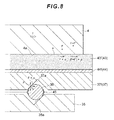
- FIG. 8 shows an enlarged view of the wedge plate 37f, the shoe plate 44f, and the inner pad 43f which have been moved to slide in the forward direction f.
- each of the rollers 36 is pressed against the inclined surface of the V-shaped wedge groove 37a corresponding to the rearward direction so that the wedge plate 37 (the shoe plate 44 and the inner pad 43 each integrated with the wedge plate 37) is pushed out relatively to each of the rollers 36 toward the outer side (toward the braking surface 4a) in such a manner as to follow the inclination of the inclined surface.
- Step S 150 a drive signal is output from the controller 91 to the electric motor 25 so as to move the wedge plate 37 to slide in the rearward direction r (Step S152).
- Step S152 a drive signal is output from the controller 91 to the electric motor 25 so as to move the wedge plate 37 to slide in the rearward direction r.
- the cam-side abutment surfaces 27b of the cam member 27 press the rack-side abutment surfaces 37d of the wedge plate 37 so that the wedge plate 37 is moved to slide in the rotating direction (which is the rearward direction r in this case) of the cam member 27.
- the caliper assembly 10 When the caliper assembly 10 is pressed toward the inner side, the caliper assembly 10 is moved by the slide pins 9 to slide toward the inner side relative to the carrier 6. As a result, the shoe plate 42 and the outer pad 41 are integrally pressed by the bridge portion 12c formed on the outer side toward the inner side so that the outer pad 41 is pressed against the braking surface 4a.
- the disk brake device 1 is configured such that, by thus pressing each of the outer pad 41 and the inner pad 43 against the braking surface 4a and holding the rotor 4 therebetween, a braking force which stops the rotation of the rotor 4 is allowed to act.
- the disk brake device 1 is configured such that, at this time, by the base plate 35, the rollers 36, and the wedge plate 37, the pressing force pressing the inner pad 43 against the braking surface 4a is automatically amplified (self-boosting is effected).
- the configuration will be described with reference to FIG. 8 . Note that, in the following, the description will be given on the assumption that a friction coefficient between the braking surface 4a and the inner pad 43 is ⁇ .
- the inner pad 43 is pressed against the braking surface 4a with a pressing force obtained by adding the counterforce F' to the original pressing force F so that a frictional force (F + F') ⁇ ⁇ corresponding to the totaled pressing force (F + F') acts on the inner pad 43.
- the disk brake device 1 is configured such that the operation in which the inner pad 43 is thus moved to slide in the forward direction f by the frictional force and the operation in which the inner pad 43 is thus pressed against the braking surface 4a with a larger pressing force are repeated to cause the pressing force of the inner pad 43 applied to the braking surface 4a to be automatically amplified.
- Step S151 or S152 the electric motor 25 is driven to rotate so as to move the wedge plate 37 to slide in the rotating direction of the rotor 4.
- Step S160 it is determined in the controller 91 whether or not the pressing force of the inner pad 43 detected in the sensor 31 when the braking force thus acts on the rotor 4 is larger than the pressing force corresponding to the braking operation force detected in the stepping force detection sensor 92a.
- Step S160 when it is determined that the detected pressing force is larger than the pressing force corresponding to the detected braking operation force, the flow advances to Step S 171 where a drive signal is output from the controller 91 to the electric motor 25 so as to move the wedge plate 37 in a direction which weakens the pressing force (move the wedge plate 37 toward the inner side).
- Step S 172 a drive signal is output from the controller 91 to the electric motor 25 so as to move the wedge plate 37 in a direction which enhances the pressing force (move the wedge plate 37 toward the outer side).
- the rotational driving of the electric motor 25 is controlled so as to press the inner pad 43 against the braking surface 4a with the pressing force corresponding to the braking operation force applied to the brake pedal 92. By doing so, it is possible to cause the braking force intended by the driver to act on the rotor 4 and decelerate the vehicle.
- the application of the present invention is not limited to the example of the configuration.
- the configuration may also be such that, instead of detecting the pressing force of the inner pad 43, a brake torque generated by pressing the inner pad 43 against the braking surface 4a is detected and fed back or the deceleration of the vehicle is detected and fed back to control the rotational driving of the electric motor 25.
- the cam member 27 having the single set of engaging teeth 27c and the wedge plate 37 formed with the insertion space 37b including the single rack which is engaged with the single set of engaging teeth 27c have been described by way of example.
- the present invention is not limited to this configuration.
- a configuration using a cam member having a plurality of sets of engaging teeth and a wedge plate formed with a cam insertion space including a plurality of racks which are simultaneously engaged with the plurality of sets of engaging teeth may also be used.
- cam member 27 including the main body portion 27a and the engaging teeth 27c has been described by way of example, but it may also be possible to use a pinion teeth member formed to include pinion teeth which transmit the rotational driving force of the electric motor 25 instead of the cam member 27 having this configuration.
- the present invention is not limited to the example of the configuration. Instead of this configuration, a configuration may also be used in which, e.g., an adjusting electric motor which drives the adjusting drive gear to rotate is separately provided and the rotational driving of the adjusting electric motor is controlled to automatically adjust the gap between the pad and the braking surface.
Landscapes
- Engineering & Computer Science (AREA)
- General Engineering & Computer Science (AREA)
- Mechanical Engineering (AREA)
- Transportation (AREA)
- Braking Arrangements (AREA)
- Braking Systems And Boosters (AREA)
Applications Claiming Priority (2)
| Application Number | Priority Date | Filing Date | Title |
|---|---|---|---|
| JP2011107678A JP2012237408A (ja) | 2011-05-12 | 2011-05-12 | ディスクブレーキ装置 |
| PCT/JP2012/002970 WO2012153502A1 (ja) | 2011-05-12 | 2012-05-02 | ディスクブレーキ装置 |
Publications (1)
| Publication Number | Publication Date |
|---|---|
| EP2708770A1 true EP2708770A1 (en) | 2014-03-19 |
Family
ID=47138990
Family Applications (1)
| Application Number | Title | Priority Date | Filing Date |
|---|---|---|---|
| EP12781993.6A Withdrawn EP2708770A1 (en) | 2011-05-12 | 2012-05-02 | Disk brake device |
Country Status (6)
| Country | Link |
|---|---|
| US (1) | US20140083804A1 (ja) |
| EP (1) | EP2708770A1 (ja) |
| JP (1) | JP2012237408A (ja) |
| KR (1) | KR101940343B1 (ja) |
| CN (1) | CN103518074A (ja) |
| WO (1) | WO2012153502A1 (ja) |
Families Citing this family (5)
| Publication number | Priority date | Publication date | Assignee | Title |
|---|---|---|---|---|
| US20150136539A1 (en) * | 2012-07-05 | 2015-05-21 | Tbk Co., Ltd. | Disk brake device |
| CN104863999A (zh) * | 2014-02-21 | 2015-08-26 | 廖志贤 | 电子式驻车卡钳 |
| US10458498B2 (en) * | 2015-04-27 | 2019-10-29 | Freni Brembo S.P.A | Locking device of an electromagnetically-operated brake caliper, brake caliper comprising said caliper, method for operating said caliper |
| WO2018042673A1 (ja) * | 2016-09-05 | 2018-03-08 | 三菱電機株式会社 | ブレーキ |
| CN109163031B (zh) * | 2018-09-26 | 2024-01-02 | 陕西法士特齿轮有限责任公司 | 一种amt中间轴制动结构 |
Family Cites Families (15)
| Publication number | Priority date | Publication date | Assignee | Title |
|---|---|---|---|---|
| NL1006542C2 (nl) * | 1997-07-10 | 1999-01-12 | Skf Ind Trading & Dev | Remklauw met slijtagecompensatie. |
| DE10154178B4 (de) | 2001-05-21 | 2004-05-13 | Estop Gmbh | Elektromechanische Bremse mit Selbstverstärkung und veränderlichem Keilwinkel |
| AU2003206572A1 (en) * | 2002-02-21 | 2003-09-09 | Haldex Brake Products Ab | A disc brake |
| SE0200495D0 (en) * | 2002-02-21 | 2002-02-21 | Haldex Brake Prod Ab | A disc brake |
| DE10328244A1 (de) * | 2003-06-24 | 2005-01-13 | Robert Bosch Gmbh | Scheibenbremse mit Selbstverstärkung |
| DE102005030621A1 (de) * | 2004-10-13 | 2006-04-20 | Knorr-Bremse Systeme für Nutzfahrzeuge GmbH | Scheibenbremse in selbstverstärkender Bauart und Ansteuerverfahren für eine selbstverstärkende Bremse |
| DE102005030618A1 (de) * | 2004-10-13 | 2006-04-20 | Knorr-Bremse Systeme für Nutzfahrzeuge GmbH | Scheibenbremse in selbstverstärkender Bauart und Ansteuerverfahren für eine selbstverstärkende Bremse |
| CN101065598B (zh) * | 2004-10-13 | 2010-12-08 | 克诺尔商用车制动系统有限公司 | 按自行增力的结构形式的盘式制动器和用于自行增力的制动器的控制方法 |
| DE102006001133A1 (de) * | 2006-01-09 | 2007-07-12 | Robert Bosch Gmbh | Elektromechanische Reibungsbremse |
| JP4959438B2 (ja) * | 2007-06-21 | 2012-06-20 | 日信工業株式会社 | ブレーキ制御装置 |
| KR100897941B1 (ko) * | 2007-09-12 | 2009-05-18 | 현대모비스 주식회사 | 솔레노이드 보조력 생성 타입 단일 모터 전자 웨지브레이크 시스템 |
| KR100897942B1 (ko) * | 2007-09-17 | 2009-05-18 | 현대모비스 주식회사 | 주차 제동력 고정 타입 단일 모터 전자 웨지 브레이크시스템 |
| DE102007055637A1 (de) * | 2007-11-21 | 2009-05-28 | Robert Bosch Gmbh | Elektromechanische Reibungsbremse |
| JP4964792B2 (ja) * | 2008-01-21 | 2012-07-04 | 曙ブレーキ工業株式会社 | 自己倍力可変式ブレーキ装置 |
| KR101098144B1 (ko) * | 2008-12-11 | 2011-12-26 | 현대모비스 주식회사 | 안전 제동 기능을 갖춘 제동 장치 |
-
2011
- 2011-05-12 JP JP2011107678A patent/JP2012237408A/ja not_active Ceased
-
2012
- 2012-05-02 US US14/116,084 patent/US20140083804A1/en not_active Abandoned
- 2012-05-02 KR KR1020137030705A patent/KR101940343B1/ko active IP Right Grant
- 2012-05-02 WO PCT/JP2012/002970 patent/WO2012153502A1/ja active Application Filing
- 2012-05-02 CN CN201280022333.3A patent/CN103518074A/zh active Pending
- 2012-05-02 EP EP12781993.6A patent/EP2708770A1/en not_active Withdrawn
Non-Patent Citations (1)
| Title |
|---|
| See references of WO2012153502A1 * |
Also Published As
| Publication number | Publication date |
|---|---|
| WO2012153502A1 (ja) | 2012-11-15 |
| KR20140026507A (ko) | 2014-03-05 |
| KR101940343B1 (ko) | 2019-01-18 |
| CN103518074A (zh) | 2014-01-15 |
| US20140083804A1 (en) | 2014-03-27 |
| JP2012237408A (ja) | 2012-12-06 |
Similar Documents
| Publication | Publication Date | Title |
|---|---|---|
| EP2708770A1 (en) | Disk brake device | |
| KR102383332B1 (ko) | 볼 스크루 타입 전동식 브레이크 | |
| KR101197477B1 (ko) | 차량용 디스크 브레이크 | |
| KR102383339B1 (ko) | 볼 스크루 타입 전동식 브레이크 | |
| KR20120064451A (ko) | 전동 브레이크 장치 | |
| US8151947B2 (en) | Single motor electronic controlled wedge brake system | |
| EP2871382A1 (en) | Disc brake device | |
| EP2871383A1 (en) | Disc brake device | |
| EP2871384A1 (en) | Disc brake device | |
| KR20210100454A (ko) | 전동식 브레이크 시스템 | |
| KR20180106135A (ko) | 기계식 디스크브레이크 | |
| KR101045905B1 (ko) | 차량용 디스크 브레이크 | |
| KR20220107460A (ko) | 전기 기계식 브레이크 | |
| JP2013029114A (ja) | ディスクブレーキ装置 | |
| KR101040947B1 (ko) | 차량용 디스크 브레이크 | |
| KR101045911B1 (ko) | 차량용 디스크 브레이크 | |
| KR101197471B1 (ko) | 차량용 디스크 브레이크의 제동제어를 위한 웨지 기준위치인식 방법 | |
| KR101197473B1 (ko) | 차량용 디스크 브레이크의 웨지위치 인식 방법 | |
| KR20080053724A (ko) | 차량용 디스크 브레이크 | |
| KR101045917B1 (ko) | 차량용 디스크 브레이크 | |
| KR20100023665A (ko) | 차량용 전자제동장치 | |
| KR101045915B1 (ko) | 차량용 디스크 브레이크 |
Legal Events
| Date | Code | Title | Description |
|---|---|---|---|
| PUAI | Public reference made under article 153(3) epc to a published international application that has entered the european phase |
Free format text: ORIGINAL CODE: 0009012 |
|
| 17P | Request for examination filed |
Effective date: 20131212 |
|
| AK | Designated contracting states |
Kind code of ref document: A1 Designated state(s): AL AT BE BG CH CY CZ DE DK EE ES FI FR GB GR HR HU IE IS IT LI LT LU LV MC MK MT NL NO PL PT RO RS SE SI SK SM TR |
|
| DAX | Request for extension of the european patent (deleted) | ||
| STAA | Information on the status of an ep patent application or granted ep patent |
Free format text: STATUS: THE APPLICATION HAS BEEN WITHDRAWN |
|
| 18W | Application withdrawn |
Effective date: 20150929 |