EP2708757A2 - Schnellentlüfter - Google Patents
Schnellentlüfter Download PDFInfo
- Publication number
- EP2708757A2 EP2708757A2 EP20130183558 EP13183558A EP2708757A2 EP 2708757 A2 EP2708757 A2 EP 2708757A2 EP 20130183558 EP20130183558 EP 20130183558 EP 13183558 A EP13183558 A EP 13183558A EP 2708757 A2 EP2708757 A2 EP 2708757A2
- Authority
- EP
- European Patent Office
- Prior art keywords
- valve
- port
- vent
- quick exhaust
- housing
- Prior art date
- Legal status (The legal status is an assumption and is not a legal conclusion. Google has not performed a legal analysis and makes no representation as to the accuracy of the status listed.)
- Granted
Links
Images

Classifications
-
- F—MECHANICAL ENGINEERING; LIGHTING; HEATING; WEAPONS; BLASTING
- F16—ENGINEERING ELEMENTS AND UNITS; GENERAL MEASURES FOR PRODUCING AND MAINTAINING EFFECTIVE FUNCTIONING OF MACHINES OR INSTALLATIONS; THERMAL INSULATION IN GENERAL
- F16K—VALVES; TAPS; COCKS; ACTUATING-FLOATS; DEVICES FOR VENTING OR AERATING
- F16K31/00—Actuating devices; Operating means; Releasing devices
- F16K31/12—Actuating devices; Operating means; Releasing devices actuated by fluid
- F16K31/36—Actuating devices; Operating means; Releasing devices actuated by fluid in which fluid from the circuit is constantly supplied to the fluid motor
- F16K31/38—Actuating devices; Operating means; Releasing devices actuated by fluid in which fluid from the circuit is constantly supplied to the fluid motor in which the fluid works directly on both sides of the fluid motor, one side being connected by means of a restricted passage and the motor being actuated by operating a discharge from that side
- F16K31/385—Actuating devices; Operating means; Releasing devices actuated by fluid in which fluid from the circuit is constantly supplied to the fluid motor in which the fluid works directly on both sides of the fluid motor, one side being connected by means of a restricted passage and the motor being actuated by operating a discharge from that side the fluid acting on a diaphragm
-
- F—MECHANICAL ENGINEERING; LIGHTING; HEATING; WEAPONS; BLASTING
- F15—FLUID-PRESSURE ACTUATORS; HYDRAULICS OR PNEUMATICS IN GENERAL
- F15B—SYSTEMS ACTING BY MEANS OF FLUIDS IN GENERAL; FLUID-PRESSURE ACTUATORS, e.g. SERVOMOTORS; DETAILS OF FLUID-PRESSURE SYSTEMS, NOT OTHERWISE PROVIDED FOR
- F15B11/00—Servomotor systems without provision for follow-up action; Circuits therefor
- F15B11/06—Servomotor systems without provision for follow-up action; Circuits therefor involving features specific to the use of a compressible medium, e.g. air, steam
-
- F—MECHANICAL ENGINEERING; LIGHTING; HEATING; WEAPONS; BLASTING
- F15—FLUID-PRESSURE ACTUATORS; HYDRAULICS OR PNEUMATICS IN GENERAL
- F15B—SYSTEMS ACTING BY MEANS OF FLUIDS IN GENERAL; FLUID-PRESSURE ACTUATORS, e.g. SERVOMOTORS; DETAILS OF FLUID-PRESSURE SYSTEMS, NOT OTHERWISE PROVIDED FOR
- F15B21/00—Common features of fluid actuator systems; Fluid-pressure actuator systems or details thereof, not covered by any other group of this subclass
- F15B21/04—Special measures taken in connection with the properties of the fluid
- F15B21/044—Removal or measurement of undissolved gas, e.g. de-aeration, venting or bleeding
-
- F—MECHANICAL ENGINEERING; LIGHTING; HEATING; WEAPONS; BLASTING
- F16—ENGINEERING ELEMENTS AND UNITS; GENERAL MEASURES FOR PRODUCING AND MAINTAINING EFFECTIVE FUNCTIONING OF MACHINES OR INSTALLATIONS; THERMAL INSULATION IN GENERAL
- F16K—VALVES; TAPS; COCKS; ACTUATING-FLOATS; DEVICES FOR VENTING OR AERATING
- F16K24/00—Devices, e.g. valves, for venting or aerating enclosures
- F16K24/04—Devices, e.g. valves, for venting or aerating enclosures for venting only
Definitions
- the invention relates to a quick exhaust according to the features of the preamble of claim 1.
- the AT 332 187 B a quick exhaust valve having the features that a housing is provided with an input port, a vent connection to the atmosphere and an output port, wherein at the vent port a vent valve is arranged.
- the vent valve is controllable depending on the pressure quotient between output port and input port, wherein in a first case of operation - ventilation - the vent valve is closed by a valve body lying in the housing, and in a second case of operation - venting - the vent valve is opened, whereby the outlet port is vented.
- the vent valve has a first control surface connected to the input port and a second control surface connected to the output port.
- the invention is characterized in that the output terminal is connected to the first control surface via an in particular adjustable choke integrated in the housing.
- the pressure compensation from output port to input port with decreasing control pressure can be adjusted to the behavior of the vent valve so that the vent valve opens only targeted.
- the control of the drive can be optimally adjusted to the needs of the application. This guarantees a reliable ventilation in emergency situations and on the other hand offers the adjustability of the pressure range for regulation.
- a through valve in particular a check valve, may be provided, which is arranged parallel to the throttle, and which blocks in a flow direction from the output port to the input port and bridges the throttle in the reverse flow direction.
- the bridging of the throttle with a check valve has the advantage that in the case of ventilation, the response of the drive is significantly improved, whereas with decreasing control pressure compared to the drive pressure, the controlled by the adjustable throttle control behavior is achieved.
- valve body of the vent valve may be in the form of a disc secured to the housing via a diaphragm, the diaphragm separating the output port and the input port together with the valve body, and closing the vent valve by seating the disc-shaped valve body on the valve seat is pressed.
- a pressure quotient for the venting case can be set precisely via the area ratios.
- the precise setting of this switching point, in conjunction with the setting of the throttle, the control performance of the quick exhaust valve can be accurately adjusted.
- the check valve has a spring, by which a pressure quotient threshold value is set in a targeted manner. As a result, the operating point of the quick exhaust valve can be adjusted.
- an adjusting means which represents a maximum stroke limitation for the valve body. Due to the particular adjustable stroke limitation, the flow factor, the so-called kv value, of the vent port can be set.
- the quick exhaust valve can be used in an arrangement comprising a positioner and a pneumatic drive, wherein the positioner is connected to the input terminal of the rapid exhaust fan and the drive to the output terminal of the quick exhaust.
- the pneumatic actuator may be a diaphragm actuator having a diaphragm chamber and a spring chamber, the output port of the quick exhaust being connected to the diaphragm chamber and the exhaust port of the quick exhaust to the spring chamber.
- the adjustment of the control by the rapid exhaust fan in a control range in which the pressure drop of the control pressure is not immediately leading to the venting of the drive is particularly important, which leads to this due to the spring-diaphragm combination to a swinging of the system ,
- vent port By connecting the vent port with the spring chamber, it is purged with each vent.
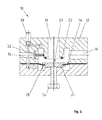
- Fig. 1 shows a sectional view of a quick exhaust 10.
- This includes a housing 12 having an input port 14, an output port 16 and a vent port 18.
- the vent port 18 vents the output 16 to atmosphere.
- the vent port 18 is connected to the outlet port 16 via a vent valve 20 comprising a valve seat 22 and a valve body 24.
- the valve body 24 consists of a disc-like sealing body which is mounted on the housing 12 movably via a membrane.
- the position of the valve body 24 is influenced by applying pressure to the first control surface 26.
- the second control surface 28 which is opposite to the first, is acted upon by the pressure prevailing at the inlet connection 14.
- the outlet port 16 is vented according to a pressure quotient of input port 14 to output port 16 set by the selection of the size of the control surfaces 26, 28. Due to the cross-sectional selection of output port 16 and vent port 18, the vent port 20 is rapidly vented to the outlet port 16.
- a check valve 32 is provided between the input terminal 14 and output terminal 16, which blocks at Auslass sometimesem overpressure. By the check valve 32, the dynamics is improved when venting the output terminal.
- a throttle is integrated in the housing to avoid a sudden venting during the control process.
- This throttle is preferably adjustable. Adjusting the throttle affects the behavior of the quick exhaust.
- an adjusting screw 34 is integrated so that a stroke limiter of the valve body 24 is adjustable. By adjusting screw 34, the flow factor of the vent port 18 can be set for the venting case.
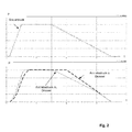
- the ratio of the first control surface 28 to the second control surface 26 is selected so that the vent valve 20 opens at a certain pressure ratio of input to output pressure.
- the pressure ratio is set to 4/5.
- the pressure on the outlet side would remain constant without throttle 30 in the case of a blocked check valve 32. This is based on the characteristic drive pressure without throttle traceable. If the control pressure is only 4/5 of the outlet-side pressure, the vent valve 20 opens. Without a throttle this is the case in the example chosen at 4.0 bar.
Landscapes
- Engineering & Computer Science (AREA)
- General Engineering & Computer Science (AREA)
- Mechanical Engineering (AREA)
- Physics & Mathematics (AREA)
- Fluid Mechanics (AREA)
- Chemical & Material Sciences (AREA)
- Analytical Chemistry (AREA)
- Check Valves (AREA)
- Fluid-Driven Valves (AREA)
- Self-Closing Valves And Venting Or Aerating Valves (AREA)
Abstract
Description
- Die Erfindung betrifft einen Schnellentlüfter gemäß den Merkmalen des Oberbegriffs des Anspruchs 1.
- Gattungsgemäße Schnellentlüfter sind den Druckschriften
DE 692 07 723 T2 ,DE 1 1 87 441 B ,DE 26 11 653 C2 undDE 1 243 484 B zu entnehmen. - Insbesondere offenbart die
AT 332 187 B - Problematisch ist dies vor allem bei der Regelung eines an den Ausgangsanschluss angeschlossenen Antriebs im Druckbereich des für die Öffnung des Entlüftungsventils erforderlichen Druckquotienten. Da in diesem Bereich das Entlüftungsventil öffnet, muss der dadurch hervorgerufene Druckabfall durch die Regelung eines Stellungsreglers ausgeglichen werden.
- Es ist Aufgabe der Erfindung ein gattungsgemäßes Schnellentlüftungsventil derart zu verbessern, dass eine Regelung des Antriebs in einem breiteren Druckspektrum möglich ist, ohne dass das Entlüftungsventil des Schnellentlüfters anspricht.
- Die Erfindung zeichnet sich dadurch aus, dass der Ausgangsanschluss über eine im Gehäuse integrierte, insbesondere einstellbare Drossel mit der ersten Steuerfläche verbunden ist.
- Durch die Integration einer einstellbaren Drossel in das Ventilgehäuse kann der Druckausgleich von Ausgangsanschluss zu Eingangsanschluss bei abfallendem Steuerdruck so auf das Verhalten des Entlüftungsventils abgestimmt werden, dass das Entlüftungsventil nur gezielt öffnet. Dadurch kann die Regelung des Antriebs auf die Bedürfnisse der Anwendung optimal eingestellt werden. Dies garantiert eine zuverlässige Entlüftung in Notfallsituationen und bietet auf der anderen Seite die Einstellbarkeit des Druckbereichs zur Regelung.
- In einer weiteren vorteilhaften Ausgestaltung der Erfindung kann ein Durchgangsventil, insbesondere ein Rückschlagventil, vorgesehen sein, welches parallel zur Drossel angeordnet ist, und welches in einer Strömungsrichtung von Ausgangsanschluss zu Eingangsanschluss sperrt und in der umgekehrten Strömungsrichtung die Drossel überbrückt.
- Die Überbrückung der Drossel mit einem Rückschlagventil hat den Vorteil, dass im Belüftungsfall das Ansprechverhalten des Antriebs erheblich verbessert wird, wohingegen bei absinkendem Steuerdruck gegenüber dem Antriebsdruck das durch die einstellbare Drossel beeinflusste Regelverhalten erzielt wird.
- Vorzugsweise kann der Ventilkörper des Entlüftungsventils in Form einer Scheibe ausgebildet sein, die über eine Membran am Gehäuse befestigt ist, wobei die Membran zusammen mit dem Ventilkörper den Ausgangsanschluss und den Eingangsanschluss voneinander trennt, und das Entlüftungsventil geschlossen wird, indem der scheibenförmige Ventilkörper auf den Ventilsitz gedrückt ist.
- Durch Membran und Ventilkörperscheibe kann über die Flächenverhältnisse ein Druckquotient für den Entlüftungsfall präzise eingestellt werden. Durch die präzise Einstellung dieses Schaltpunkts kann in Verbindung mit der Einstellung der Drossel das Regelverhalten des Schnellentlüftungsventils genau eingestellt werden.
- In einer weiteren Ausführung kann vorgesehen sein, dass das Rückschlagventil eine Feder aufweist, durch die ein Druckquotient-Schwellwert gezielt eingestellt wird. Dadurch kann der Arbeitspunkt des Schnellentlüftungsventils eingestellt werden.
- Ferner ist ein Einstellmittel vorgesehen, welches eine maximale Hubbegrenzung für den Ventilkörper darstellt. Durch die insbesondere einstellbare Hubbegrenzung kann der Durchflussfaktor, der sogenannte kv-Wert, des Entlüftungsanschlusses festgelegt werden.
- Besonders vorteilhaft kann das Schnellentlüftungsventil in einer Anordnung, umfassend einen Stellungsregler und einen pneumatischen Antrieb, eingesetzt werden, wobei der Stellungsregler mit dem Eingangsanschluss des Schnellentlüfters und der Antrieb mit dem Ausgangsanschluss des Schnellentlüfters verbunden ist.
- Vorzugsweise kann in einer solchen Anordnung der pneumatische Antrieb ein Membranantrieb sein, der eine Membrankammer und eine Federkammer aufweist, wobei der Ausgangsanschluss des Schnellentlüfters mit der Membrankammer und der Entlüftungsanschluss der Schnellentlüfters mit der Federkammer verbunden ist.
- Gerade in einer Anordnung unter Verwendung eines Membranantriebs ist die Einstellung der Regelung durch den Schnellentlüfter in einem Regelbereich bei dem der Druckabfall des Steuerdrucks nicht sofort zur Entlüftung des Antriebs führt besonders wichtig, das durch dies aufgrund der Feder- Membran Kombination zu einem Aufschwingen des Systems führt.
- Durch die Verbindung des Entlüftungsanschlusses mit der Federkammer wird diese bei jeder Entlüftung gespült.
- Weitere Vorteile, Merkmale und Anwendungsmöglichkeiten der vorliegenden Erfindung ergeben sich aus der nachfolgenden Beschreibung in Verbindung mit den in den Zeichnungen dargestellten Ausführungsbeispielen.
- In der Beschreibung, in den Ansprüchen und in der Zeichnung werden die in der unten aufgeführten Liste der Bezugszeichen verwendeten Begriffe und zugeordneten Bezugszeichen verwendet. In der Zeichnung bedeutet:
- Fig. 1
- eine Schnittansicht eines Schnellentlüfters und
- Fig. 2
- eine durch die Drosseleinstellung angepasstes Druckverhalten des erfindungsgemäßen Schnellentlüftungsventils.
-
Fig. 1 zeigt eine Schnittansicht eines Schnellentlüfters 10. Dieser umfasst ein Gehäuse 12 mit einem Eingangsanschluss 14, einem Ausgangsanschluss 16 sowie einem Entlüftungsanschluss 18. Der Entlüftungsanschluss 18 entlüftet den Ausgang 16 gegen Atmosphäre. Der Entlüftungsanschluss 18 ist über ein Entlüftungsventil 20, umfassend einen Ventilsitz 22 und einen Ventilkörper 24, mit dem Ausgangsanschluss 16 verbunden. Der Ventilkörper 24 besteht aus einem scheibenartigen Dichtkörper, der über eine Membran beweglich am Gehäuse 12 gelagert ist. Die Lage des Ventilkörpers 24 wird beeinflusst, indem ein Druck auf die erste Steuerfläche 26 ausgeübt wird. Die zweite Steuerfläche 28, die der ersten gegenüber liegt, wird mit dem Druck, der am Eingangsanschluss 14 herrscht, beaufschlagt. Eine Entlüftung des Ausgangsanschlusses 16 erfolgt gemäß einem durch die Wahl der Größe der Steuerflächen 26, 28 eingestellten Druckquotienten von Eingangsanschluss 14 zu Ausgangsanschluss 16. Aufgrund der Querschnittswahl von Ausgangsanschluss 16 und Entlüftungsanschluss 18 erfolgt bei Öffnung des Entlüftungsventils 20 ein schnelles Entlüften des Ausgangsanschlusses 16. - Ferner ist zwischen Eingangsanschluss 14 und Ausgangsanschluss 16 ein Rückschlagventil 32 vorgesehen, welches bei auslassseitigem Überdruck sperrt. Durch das Rückschlagventil 32 wird die Dynamik bei Belüften des Ausgangsanschlusses verbessert.
- Im Übergang von Eingangs- zu Ausgangsanschluss 16 ist eine Drossel im Gehäuse integriert, um ein schlagartiges Entlüften während des Regelvorgangs zu vermeiden. Diese Drossel ist vorzugsweise einstellbar. Durch die Einstellung der Drossel wird das Verhalten des Schnellentlüfters beeinflusst.
- Zudem ist eine Einstellschraube 34 so integriert, dass eine Hubbegrenzung des Ventilkörpers 24 einstellbar ist. Durch die Einstellschraube 34 kann der Durchflussfaktor des Entlüftungsanschlusses 18 für den Entlüftungsfall eingestellt werden.
- Wie in
Fig. 2 dargestellt, ist das Verhältnis von erster Steuerfläche 28 zu zweiter Steuerfläche 26 so gewählt, dass das Entlüftungsventil 20 bei einem bestimmten Druckverhältnis von Eingangs- zu Ausgangsdruck öffnet. Im vorliegenden Fall ist das Druckverhältnis auf 4/5 eingestellt. Bei abnehmendem Steuerdruck würde ohne Drossel 30 bei einem gesperrten Rückschlagventil 32 der Druck auslassseitig konstant bleiben. Dies ist anhand der Kennlinie Antriebsdruck ohne Drossel nachvollziehbar. Beträgt der Steuerdruck nur noch 4/5 des auslassseitigen Drucks, öffnet das Entlüftungsventil 20. Ohne Drossel ist dies im gewählten Beispiel bei 4,0 bar der Fall. Mit der gewählten Drosseleinstellung hingegen, kann über die Drossel ein Druckausgleich mit der Einlassseite des Schnellentlüfters erfolgen, wodurch eine Druckabsenkung bis 2,5 bar möglich ist, bis das notwendige Druckverhältnis von 4/5 erreicht ist, um das Entlüftungsventil 20 zu öffnen. Dies ist anhand der Kennlinie Antriebsdruck mit Drossel dargestellt. Dies hat zur Folge, dass eine Ansteuerung des Antriebes durch das Entlüftungsventil 20 hindurch bis zu einer deutlich niedrigeren Absolutdruckzahl möglich ist, ohne dass das Entlüftungsventil 20 auslöst. Dadurch wird eine hohe Regelgüte der Antriebsposition auch im Betriebszustand Entlüften und auch bei kleinen Sollwertänderungen möglich. -
- 10
- Schnellentlüfter
- 12
- Gehäuse
- 14
- Eingangsanschluss
- 16
- Ausgangsanschluss
- 18
- Entlüftungsanschluss
- 20
- Entlüftungsventil
- 22
- Ventilsitz
- 24
- Ventilkörper
- 26
- zweite Steuerfläche
- 28
- erste Steuerfläche
- 30
- Drossel
- 32
- Rückschlagventil
- 34
- Einstellschraube
Claims (8)
- Schnellentlüfter (10), umfassend ein Gehäuse (12) mit einem Eingangsanschluss (14), einem Entlüftungsanschluss (18) gegen Atmosphäre und einem Ausgangsanschluss (16), wobei am Entlüftungsanschluss (18) ein Entlüftungsventil (20) vorgesehen ist, welches abhängig von Druckquotienten von Eingangsanschluss (14) zu Ausgangsanschluss (16) und ansteuerbar ist, wobei in einem ersten Betriebsfall - Belüftung - das Entlüftungsventil (20) durch einen im Gehäuse (12) liegenden Ventilkörper (24) geschlossen ist, und in einem zweiten Betriebsfall - Entlüftung - das Entlüftungsventil (20) geöffnet ist, wodurch der Ausgangsanschluss (16) entlüftet wird und ferner das Entlüftungsventil (20) eine erste Steuerfläche (28) aufweist, die mit dem Eingangsanschluss (14) verbunden ist und eine zweite Steuerfläche (26) aufweist, die mit dem Ausgangsanschluss (16) verbunden ist, dadurch gekennzeichnet, dass der Ausgangsanschluss (16) über eine im Gehäuse (12) integrierte Drossel (30) mit der ersten Steuerfläche (28) verbunden ist.
- Schnellentlüfter nach Anspruch 1, dadurch gekennzeichnet, dass die integrierte Drossel eine einstellbare Drossel (30) ist.
- Schnellentlüfter nach Anspruch 1 oder 2, dadurch gekennzeichnet, dass ein Durchgangsventil vorgesehen ist, insbesondere ein Rückschlagventil (32), welches parallel zur einstellbaren Drossel (30) angeordnet ist, und welches in einer Strömungsrichtung vom Ausgangsanschluss (16) zum Eingangsanschluss (14) sperrt und in der umgekehrten Strömungsrichtung die einstellbare Drossel (30) überbrückt.
- Schnellentlüfter nach einem der Ansprüche 1 bis 3, dadurch gekennzeichnet, dass der Ventilkörper (24) in Form einer Scheibe ausgebildet ist, die über eine Membran am Gehäuse (12) befestigt ist, wobei die Membran mit dem Ventilkörper (24) einen Ausgangsanschluss (16) und Eingangsanschluss (14) trennt, und das Entlüftungsventil (20) geschlossen wird, indem der scheibenförmige Ventilkörper (24) auf einen Ventilsitz (22) des Entlüftungsventils (20) gedrückt wird.
- Schnellentlüfter nach einem der Ansprüche 3 oder 4, dadurch gekennzeichnet, dass das Rückschlagventil (32) eine Feder aufweist, durch die der zur Öffnung des Entlüftungsventils (20) notwendige Druckquotient einstellbar ist.
- Schnellentlüfter nach einem der vorangehenden Ansprüche, dadurch gekennzeichnet, dass ein Einstellmittel (34) vorgesehen ist, das den maximalen Hub des Ventilkörpers (24) beschränkt.
- Anordnung umfassend einen Stellungsregler, einen pneumatischen Antrieb und einen Schnellentlüfter (10) nach einem der vorangehenden Ansprüche, wobei ein pneumatischer Stellungsregeler mit dem Eingangsanschluss (14) des Schnellentlüfters (10) und der Antrieb mit dem Ausgangsanschluss (16) des Schnellentlüfters (10) verbunden ist.
- Anordnung nach dem vorangehenden Anspruch 7, dadurch gekennzeichnet, dass der pneumatische Antrieb ein Membranantrieb ist, der eine Membrankammer und eine Federkammer aufweist, wobei der Ausgangsanschluss (16) der Schnellentlüfteranordnung mit der Membrankammer und der Entlüftungsanschluss (18) der Schnellentlüfteranordnung mit der Federkammer verbunden ist.
Applications Claiming Priority (1)
| Application Number | Priority Date | Filing Date | Title |
|---|---|---|---|
| DE201210108559 DE102012108559B3 (de) | 2012-09-13 | 2012-09-13 | Schnellentlüfter |
Publications (3)
| Publication Number | Publication Date |
|---|---|
| EP2708757A2 true EP2708757A2 (de) | 2014-03-19 |
| EP2708757A3 EP2708757A3 (de) | 2015-05-27 |
| EP2708757B1 EP2708757B1 (de) | 2017-12-13 |
Family
ID=49223532
Family Applications (1)
| Application Number | Title | Priority Date | Filing Date |
|---|---|---|---|
| EP13183558.9A Active EP2708757B1 (de) | 2012-09-13 | 2013-09-09 | Schnellentlüfter |
Country Status (2)
| Country | Link |
|---|---|
| EP (1) | EP2708757B1 (de) |
| DE (1) | DE102012108559B3 (de) |
Citations (5)
| Publication number | Priority date | Publication date | Assignee | Title |
|---|---|---|---|---|
| DE1187441B (de) | 1960-09-09 | 1965-02-18 | Siemens Ag | Selbsttaetige Schnellentlueftungseinrichtung fuer Druckluftantriebe, insbesondere fuer druckluftbetaetigte Schaltgeraete |
| DE1243484B (de) | 1964-07-25 | 1967-06-29 | Liebknecht Transformat | Ventil zur selbsttaetigen raschen Entlueftung eines Druckraumes |
| AT332187B (de) | 1973-01-17 | 1976-09-10 | Festo Maschf Stoll G | Schnellentluftungsventil |
| DE2611653C2 (de) | 1976-03-19 | 1985-09-26 | Bauknecht Feuerschutz Gmbh, 7550 Rastatt | Sprinkleranlage |
| DE69207723T2 (de) | 1991-11-14 | 1996-09-19 | Smc K.K., Tokio/Tokyo | Entlüftungsventil |
Family Cites Families (5)
| Publication number | Priority date | Publication date | Assignee | Title |
|---|---|---|---|---|
| US2716997A (en) * | 1949-11-28 | 1955-09-06 | Exxon Research Engineering Co | Quick release timing valve |
| US4878513A (en) * | 1988-09-28 | 1989-11-07 | Gt Development Corporation | Quick vent valve for air brake line |
| US5240271A (en) * | 1991-11-07 | 1993-08-31 | Midland Brake, Inc. | Tractor-mounted integrated gladhand and quick-release valve for tractor-trailer highway vehicles |
| US5337788A (en) * | 1993-10-22 | 1994-08-16 | Robertshaw Controls Company | Pneumatic valve with slow start and quick exhaust |
| DE29605420U1 (de) * | 1996-03-23 | 1996-06-13 | Festo Kg, 73734 Esslingen | Schnellentlüftungsventil für pneumatische Anwendungen |
-
2012
- 2012-09-13 DE DE201210108559 patent/DE102012108559B3/de active Active
-
2013
- 2013-09-09 EP EP13183558.9A patent/EP2708757B1/de active Active
Patent Citations (5)
| Publication number | Priority date | Publication date | Assignee | Title |
|---|---|---|---|---|
| DE1187441B (de) | 1960-09-09 | 1965-02-18 | Siemens Ag | Selbsttaetige Schnellentlueftungseinrichtung fuer Druckluftantriebe, insbesondere fuer druckluftbetaetigte Schaltgeraete |
| DE1243484B (de) | 1964-07-25 | 1967-06-29 | Liebknecht Transformat | Ventil zur selbsttaetigen raschen Entlueftung eines Druckraumes |
| AT332187B (de) | 1973-01-17 | 1976-09-10 | Festo Maschf Stoll G | Schnellentluftungsventil |
| DE2611653C2 (de) | 1976-03-19 | 1985-09-26 | Bauknecht Feuerschutz Gmbh, 7550 Rastatt | Sprinkleranlage |
| DE69207723T2 (de) | 1991-11-14 | 1996-09-19 | Smc K.K., Tokio/Tokyo | Entlüftungsventil |
Also Published As
| Publication number | Publication date |
|---|---|
| EP2708757A3 (de) | 2015-05-27 |
| DE102012108559B3 (de) | 2014-05-28 |
| EP2708757B1 (de) | 2017-12-13 |
Similar Documents
| Publication | Publication Date | Title |
|---|---|---|
| DE10232647B4 (de) | Regeleinrichtung für Gasbrenner | |
| EP2379385B1 (de) | Kombiniertes druckbegrenzungs- und überströmerventil | |
| EP1758007B1 (de) | Fluidbetätigter Stellungsregler | |
| DE102015215774A1 (de) | Druck- und temperaturgesteuertes Ventil in einem Ölkreislauf einer Brennkraftmaschine | |
| EP2277089B1 (de) | Druckstellglied, insbesondere farbdruckregler oder beschichtungsmittelventil | |
| DE1272601B (de) | Druckregler | |
| EP3515767B1 (de) | Druckregelventil für ein luftaufbereitungssystem eines nutzfahrzeugs | |
| EP2236781B1 (de) | Druckregelventil | |
| EP0451543B1 (de) | Antrieb für ein Dampfstellventil | |
| CH668814A5 (de) | Vorgesteuertes druckbegrenzungsventil. | |
| DE8130788U1 (de) | Druckregler | |
| DE2118970C3 (de) | Druckregler | |
| DE102019108070A1 (de) | Schwingungsdämpfer und Fahrzeug | |
| EP2708757B1 (de) | Schnellentlüfter | |
| EP1382909B1 (de) | Regeleinrichtung für Gasbrenner | |
| DE1917079C3 (de) | Pneumatischer Verstärker | |
| EP3979035B1 (de) | Domdruckregler | |
| DE102017131146A1 (de) | Regelventilbaugruppe | |
| DE202013000913U1 (de) | Vakuumpumpe insbesondere Wälzkolbenpumpe | |
| DE2719523C3 (de) | Gasventil | |
| DE102024201857A1 (de) | Pneumatisches Druckregelventil | |
| DE202023107637U1 (de) | Regler mit Überdrucksicherung | |
| DE4001675C2 (de) | Gas-Druckregelgerät | |
| DE102024201853A1 (de) | Pneumatisches Druckregelventil | |
| EP0301202B1 (de) | Ventileinrichtung für Druckmittel |
Legal Events
| Date | Code | Title | Description |
|---|---|---|---|
| PUAI | Public reference made under article 153(3) epc to a published international application that has entered the european phase |
Free format text: ORIGINAL CODE: 0009012 |
|
| AK | Designated contracting states |
Kind code of ref document: A2 Designated state(s): AL AT BE BG CH CY CZ DE DK EE ES FI FR GB GR HR HU IE IS IT LI LT LU LV MC MK MT NL NO PL PT RO RS SE SI SK SM TR |
|
| AX | Request for extension of the european patent |
Extension state: BA ME |
|
| PUAL | Search report despatched |
Free format text: ORIGINAL CODE: 0009013 |
|
| AK | Designated contracting states |
Kind code of ref document: A3 Designated state(s): AL AT BE BG CH CY CZ DE DK EE ES FI FR GB GR HR HU IE IS IT LI LT LU LV MC MK MT NL NO PL PT RO RS SE SI SK SM TR |
|
| AX | Request for extension of the european patent |
Extension state: BA ME |
|
| RIC1 | Information provided on ipc code assigned before grant |
Ipc: F15B 11/06 20060101ALI20150421BHEP Ipc: F15B 21/04 20060101ALI20150421BHEP Ipc: F16K 31/385 20060101ALI20150421BHEP Ipc: F15B 13/042 20060101AFI20150421BHEP |
|
| 17P | Request for examination filed |
Effective date: 20151127 |
|
| RBV | Designated contracting states (corrected) |
Designated state(s): AL AT BE BG CH CY CZ DE DK EE ES FI FR GB GR HR HU IE IS IT LI LT LU LV MC MK MT NL NO PL PT RO RS SE SI SK SM TR |
|
| GRAP | Despatch of communication of intention to grant a patent |
Free format text: ORIGINAL CODE: EPIDOSNIGR1 |
|
| STAA | Information on the status of an ep patent application or granted ep patent |
Free format text: STATUS: GRANT OF PATENT IS INTENDED |
|
| INTG | Intention to grant announced |
Effective date: 20170712 |
|
| GRAS | Grant fee paid |
Free format text: ORIGINAL CODE: EPIDOSNIGR3 |
|
| GRAA | (expected) grant |
Free format text: ORIGINAL CODE: 0009210 |
|
| STAA | Information on the status of an ep patent application or granted ep patent |
Free format text: STATUS: THE PATENT HAS BEEN GRANTED |
|
| AK | Designated contracting states |
Kind code of ref document: B1 Designated state(s): AL AT BE BG CH CY CZ DE DK EE ES FI FR GB GR HR HU IE IS IT LI LT LU LV MC MK MT NL NO PL PT RO RS SE SI SK SM TR |
|
| REG | Reference to a national code |
Ref country code: GB Ref legal event code: FG4D Free format text: NOT ENGLISH |
|
| REG | Reference to a national code |
Ref country code: AT Ref legal event code: REF Ref document number: 954688 Country of ref document: AT Kind code of ref document: T Effective date: 20171215 Ref country code: CH Ref legal event code: EP |
|
| REG | Reference to a national code |
Ref country code: IE Ref legal event code: FG4D Free format text: LANGUAGE OF EP DOCUMENT: GERMAN |
|
| REG | Reference to a national code |
Ref country code: DE Ref legal event code: R096 Ref document number: 502013009000 Country of ref document: DE |
|
| REG | Reference to a national code |
Ref country code: NL Ref legal event code: MP Effective date: 20171213 |
|
| REG | Reference to a national code |
Ref country code: LT Ref legal event code: MG4D |
|
| PG25 | Lapsed in a contracting state [announced via postgrant information from national office to epo] |
Ref country code: LT Free format text: LAPSE BECAUSE OF FAILURE TO SUBMIT A TRANSLATION OF THE DESCRIPTION OR TO PAY THE FEE WITHIN THE PRESCRIBED TIME-LIMIT Effective date: 20171213 Ref country code: NO Free format text: LAPSE BECAUSE OF FAILURE TO SUBMIT A TRANSLATION OF THE DESCRIPTION OR TO PAY THE FEE WITHIN THE PRESCRIBED TIME-LIMIT Effective date: 20180313 Ref country code: SE Free format text: LAPSE BECAUSE OF FAILURE TO SUBMIT A TRANSLATION OF THE DESCRIPTION OR TO PAY THE FEE WITHIN THE PRESCRIBED TIME-LIMIT Effective date: 20171213 Ref country code: FI Free format text: LAPSE BECAUSE OF FAILURE TO SUBMIT A TRANSLATION OF THE DESCRIPTION OR TO PAY THE FEE WITHIN THE PRESCRIBED TIME-LIMIT Effective date: 20171213 |
|
| PG25 | Lapsed in a contracting state [announced via postgrant information from national office to epo] |
Ref country code: LV Free format text: LAPSE BECAUSE OF FAILURE TO SUBMIT A TRANSLATION OF THE DESCRIPTION OR TO PAY THE FEE WITHIN THE PRESCRIBED TIME-LIMIT Effective date: 20171213 Ref country code: HR Free format text: LAPSE BECAUSE OF FAILURE TO SUBMIT A TRANSLATION OF THE DESCRIPTION OR TO PAY THE FEE WITHIN THE PRESCRIBED TIME-LIMIT Effective date: 20171213 Ref country code: BG Free format text: LAPSE BECAUSE OF FAILURE TO SUBMIT A TRANSLATION OF THE DESCRIPTION OR TO PAY THE FEE WITHIN THE PRESCRIBED TIME-LIMIT Effective date: 20180313 Ref country code: GR Free format text: LAPSE BECAUSE OF FAILURE TO SUBMIT A TRANSLATION OF THE DESCRIPTION OR TO PAY THE FEE WITHIN THE PRESCRIBED TIME-LIMIT Effective date: 20180314 Ref country code: RS Free format text: LAPSE BECAUSE OF FAILURE TO SUBMIT A TRANSLATION OF THE DESCRIPTION OR TO PAY THE FEE WITHIN THE PRESCRIBED TIME-LIMIT Effective date: 20171213 |
|
| PG25 | Lapsed in a contracting state [announced via postgrant information from national office to epo] |
Ref country code: NL Free format text: LAPSE BECAUSE OF FAILURE TO SUBMIT A TRANSLATION OF THE DESCRIPTION OR TO PAY THE FEE WITHIN THE PRESCRIBED TIME-LIMIT Effective date: 20171213 |
|
| PG25 | Lapsed in a contracting state [announced via postgrant information from national office to epo] |
Ref country code: CZ Free format text: LAPSE BECAUSE OF FAILURE TO SUBMIT A TRANSLATION OF THE DESCRIPTION OR TO PAY THE FEE WITHIN THE PRESCRIBED TIME-LIMIT Effective date: 20171213 Ref country code: SK Free format text: LAPSE BECAUSE OF FAILURE TO SUBMIT A TRANSLATION OF THE DESCRIPTION OR TO PAY THE FEE WITHIN THE PRESCRIBED TIME-LIMIT Effective date: 20171213 Ref country code: CY Free format text: LAPSE BECAUSE OF FAILURE TO SUBMIT A TRANSLATION OF THE DESCRIPTION OR TO PAY THE FEE WITHIN THE PRESCRIBED TIME-LIMIT Effective date: 20171213 Ref country code: EE Free format text: LAPSE BECAUSE OF FAILURE TO SUBMIT A TRANSLATION OF THE DESCRIPTION OR TO PAY THE FEE WITHIN THE PRESCRIBED TIME-LIMIT Effective date: 20171213 Ref country code: ES Free format text: LAPSE BECAUSE OF FAILURE TO SUBMIT A TRANSLATION OF THE DESCRIPTION OR TO PAY THE FEE WITHIN THE PRESCRIBED TIME-LIMIT Effective date: 20171213 |
|
| PG25 | Lapsed in a contracting state [announced via postgrant information from national office to epo] |
Ref country code: RO Free format text: LAPSE BECAUSE OF FAILURE TO SUBMIT A TRANSLATION OF THE DESCRIPTION OR TO PAY THE FEE WITHIN THE PRESCRIBED TIME-LIMIT Effective date: 20171213 Ref country code: IT Free format text: LAPSE BECAUSE OF FAILURE TO SUBMIT A TRANSLATION OF THE DESCRIPTION OR TO PAY THE FEE WITHIN THE PRESCRIBED TIME-LIMIT Effective date: 20171213 Ref country code: IS Free format text: LAPSE BECAUSE OF FAILURE TO SUBMIT A TRANSLATION OF THE DESCRIPTION OR TO PAY THE FEE WITHIN THE PRESCRIBED TIME-LIMIT Effective date: 20180413 Ref country code: SM Free format text: LAPSE BECAUSE OF FAILURE TO SUBMIT A TRANSLATION OF THE DESCRIPTION OR TO PAY THE FEE WITHIN THE PRESCRIBED TIME-LIMIT Effective date: 20171213 Ref country code: PL Free format text: LAPSE BECAUSE OF FAILURE TO SUBMIT A TRANSLATION OF THE DESCRIPTION OR TO PAY THE FEE WITHIN THE PRESCRIBED TIME-LIMIT Effective date: 20171213 |
|
| REG | Reference to a national code |
Ref country code: DE Ref legal event code: R097 Ref document number: 502013009000 Country of ref document: DE |
|
| REG | Reference to a national code |
Ref country code: FR Ref legal event code: PLFP Year of fee payment: 6 |
|
| PG25 | Lapsed in a contracting state [announced via postgrant information from national office to epo] |
Ref country code: MT Free format text: LAPSE BECAUSE OF FAILURE TO SUBMIT A TRANSLATION OF THE DESCRIPTION OR TO PAY THE FEE WITHIN THE PRESCRIBED TIME-LIMIT Effective date: 20171213 |
|
| PLBE | No opposition filed within time limit |
Free format text: ORIGINAL CODE: 0009261 |
|
| STAA | Information on the status of an ep patent application or granted ep patent |
Free format text: STATUS: NO OPPOSITION FILED WITHIN TIME LIMIT |
|
| 26N | No opposition filed |
Effective date: 20180914 |
|
| PG25 | Lapsed in a contracting state [announced via postgrant information from national office to epo] |
Ref country code: DK Free format text: LAPSE BECAUSE OF FAILURE TO SUBMIT A TRANSLATION OF THE DESCRIPTION OR TO PAY THE FEE WITHIN THE PRESCRIBED TIME-LIMIT Effective date: 20171213 |
|
| PG25 | Lapsed in a contracting state [announced via postgrant information from national office to epo] |
Ref country code: SI Free format text: LAPSE BECAUSE OF FAILURE TO SUBMIT A TRANSLATION OF THE DESCRIPTION OR TO PAY THE FEE WITHIN THE PRESCRIBED TIME-LIMIT Effective date: 20171213 |
|
| PG25 | Lapsed in a contracting state [announced via postgrant information from national office to epo] |
Ref country code: MC Free format text: LAPSE BECAUSE OF FAILURE TO SUBMIT A TRANSLATION OF THE DESCRIPTION OR TO PAY THE FEE WITHIN THE PRESCRIBED TIME-LIMIT Effective date: 20171213 |
|
| REG | Reference to a national code |
Ref country code: CH Ref legal event code: PL |
|
| REG | Reference to a national code |
Ref country code: BE Ref legal event code: MM Effective date: 20180930 |
|
| REG | Reference to a national code |
Ref country code: IE Ref legal event code: MM4A |
|
| PG25 | Lapsed in a contracting state [announced via postgrant information from national office to epo] |
Ref country code: LU Free format text: LAPSE BECAUSE OF NON-PAYMENT OF DUE FEES Effective date: 20180909 |
|
| PG25 | Lapsed in a contracting state [announced via postgrant information from national office to epo] |
Ref country code: IE Free format text: LAPSE BECAUSE OF NON-PAYMENT OF DUE FEES Effective date: 20180909 |
|
| PG25 | Lapsed in a contracting state [announced via postgrant information from national office to epo] |
Ref country code: LI Free format text: LAPSE BECAUSE OF NON-PAYMENT OF DUE FEES Effective date: 20180930 Ref country code: CH Free format text: LAPSE BECAUSE OF NON-PAYMENT OF DUE FEES Effective date: 20180930 Ref country code: BE Free format text: LAPSE BECAUSE OF NON-PAYMENT OF DUE FEES Effective date: 20180930 |
|
| REG | Reference to a national code |
Ref country code: AT Ref legal event code: MM01 Ref document number: 954688 Country of ref document: AT Kind code of ref document: T Effective date: 20180909 |
|
| PG25 | Lapsed in a contracting state [announced via postgrant information from national office to epo] |
Ref country code: AT Free format text: LAPSE BECAUSE OF NON-PAYMENT OF DUE FEES Effective date: 20180909 |
|
| PG25 | Lapsed in a contracting state [announced via postgrant information from national office to epo] |
Ref country code: TR Free format text: LAPSE BECAUSE OF FAILURE TO SUBMIT A TRANSLATION OF THE DESCRIPTION OR TO PAY THE FEE WITHIN THE PRESCRIBED TIME-LIMIT Effective date: 20171213 |
|
| PG25 | Lapsed in a contracting state [announced via postgrant information from national office to epo] |
Ref country code: HU Free format text: LAPSE BECAUSE OF FAILURE TO SUBMIT A TRANSLATION OF THE DESCRIPTION OR TO PAY THE FEE WITHIN THE PRESCRIBED TIME-LIMIT; INVALID AB INITIO Effective date: 20130909 Ref country code: PT Free format text: LAPSE BECAUSE OF FAILURE TO SUBMIT A TRANSLATION OF THE DESCRIPTION OR TO PAY THE FEE WITHIN THE PRESCRIBED TIME-LIMIT Effective date: 20171213 |
|
| PG25 | Lapsed in a contracting state [announced via postgrant information from national office to epo] |
Ref country code: MK Free format text: LAPSE BECAUSE OF NON-PAYMENT OF DUE FEES Effective date: 20171213 |
|
| PG25 | Lapsed in a contracting state [announced via postgrant information from national office to epo] |
Ref country code: AL Free format text: LAPSE BECAUSE OF FAILURE TO SUBMIT A TRANSLATION OF THE DESCRIPTION OR TO PAY THE FEE WITHIN THE PRESCRIBED TIME-LIMIT Effective date: 20171213 |
|
| P01 | Opt-out of the competence of the unified patent court (upc) registered |
Effective date: 20230713 |
|
| PGFP | Annual fee paid to national office [announced via postgrant information from national office to epo] |
Ref country code: DE Payment date: 20250919 Year of fee payment: 13 |
|
| PGFP | Annual fee paid to national office [announced via postgrant information from national office to epo] |
Ref country code: GB Payment date: 20250918 Year of fee payment: 13 |
|
| PGFP | Annual fee paid to national office [announced via postgrant information from national office to epo] |
Ref country code: FR Payment date: 20250922 Year of fee payment: 13 |