EP2708662B1 - System for controlling construction machine - Google Patents
System for controlling construction machine Download PDFInfo
- Publication number
- EP2708662B1 EP2708662B1 EP12782784.8A EP12782784A EP2708662B1 EP 2708662 B1 EP2708662 B1 EP 2708662B1 EP 12782784 A EP12782784 A EP 12782784A EP 2708662 B1 EP2708662 B1 EP 2708662B1
- Authority
- EP
- European Patent Office
- Prior art keywords
- component
- revolution speed
- engine revolution
- pump torque
- engine
- Prior art date
- Legal status (The legal status is an assumption and is not a legal conclusion. Google has not performed a legal analysis and makes no representation as to the accuracy of the status listed.)
- Not-in-force
Links
- 238000010276 construction Methods 0.000 title claims description 26
- 230000007423 decrease Effects 0.000 claims description 71
- 239000012530 fluid Substances 0.000 claims description 49
- 239000000446 fuel Substances 0.000 claims description 28
- 230000005477 standard model Effects 0.000 description 28
- 238000010586 diagram Methods 0.000 description 10
- 230000003247 decreasing effect Effects 0.000 description 8
- 238000012937 correction Methods 0.000 description 6
- 238000006073 displacement reaction Methods 0.000 description 5
- 230000000694 effects Effects 0.000 description 4
- 230000010365 information processing Effects 0.000 description 4
- 238000002347 injection Methods 0.000 description 4
- 239000007924 injection Substances 0.000 description 4
- 238000004891 communication Methods 0.000 description 3
- 238000012217 deletion Methods 0.000 description 3
- 230000037430 deletion Effects 0.000 description 3
- 238000012544 monitoring process Methods 0.000 description 2
- 238000003825 pressing Methods 0.000 description 2
- 238000013024 troubleshooting Methods 0.000 description 2
- 238000010521 absorption reaction Methods 0.000 description 1
- 230000015556 catabolic process Effects 0.000 description 1
- 239000000498 cooling water Substances 0.000 description 1
- 238000006731 degradation reaction Methods 0.000 description 1
- 230000001419 dependent effect Effects 0.000 description 1
- 238000001514 detection method Methods 0.000 description 1
- 230000014509 gene expression Effects 0.000 description 1
- 238000004519 manufacturing process Methods 0.000 description 1
- 238000000034 method Methods 0.000 description 1
- 238000012545 processing Methods 0.000 description 1
- 230000006641 stabilisation Effects 0.000 description 1
- 238000011105 stabilization Methods 0.000 description 1
Images


Classifications
-
- E—FIXED CONSTRUCTIONS
- E02—HYDRAULIC ENGINEERING; FOUNDATIONS; SOIL SHIFTING
- E02F—DREDGING; SOIL-SHIFTING
- E02F9/00—Component parts of dredgers or soil-shifting machines, not restricted to one of the kinds covered by groups E02F3/00 - E02F7/00
- E02F9/20—Drives; Control devices
- E02F9/22—Hydraulic or pneumatic drives
- E02F9/2221—Control of flow rate; Load sensing arrangements
- E02F9/2232—Control of flow rate; Load sensing arrangements using one or more variable displacement pumps
- E02F9/2235—Control of flow rate; Load sensing arrangements using one or more variable displacement pumps including an electronic controller
-
- E—FIXED CONSTRUCTIONS
- E02—HYDRAULIC ENGINEERING; FOUNDATIONS; SOIL SHIFTING
- E02F—DREDGING; SOIL-SHIFTING
- E02F9/00—Component parts of dredgers or soil-shifting machines, not restricted to one of the kinds covered by groups E02F3/00 - E02F7/00
- E02F9/20—Drives; Control devices
- E02F9/22—Hydraulic or pneumatic drives
- E02F9/2246—Control of prime movers, e.g. depending on the hydraulic load of work tools
-
- E—FIXED CONSTRUCTIONS
- E02—HYDRAULIC ENGINEERING; FOUNDATIONS; SOIL SHIFTING
- E02F—DREDGING; SOIL-SHIFTING
- E02F9/00—Component parts of dredgers or soil-shifting machines, not restricted to one of the kinds covered by groups E02F3/00 - E02F7/00
- E02F9/20—Drives; Control devices
- E02F9/22—Hydraulic or pneumatic drives
- E02F9/2278—Hydraulic circuits
- E02F9/2296—Systems with a variable displacement pump
-
- E—FIXED CONSTRUCTIONS
- E02—HYDRAULIC ENGINEERING; FOUNDATIONS; SOIL SHIFTING
- E02F—DREDGING; SOIL-SHIFTING
- E02F9/00—Component parts of dredgers or soil-shifting machines, not restricted to one of the kinds covered by groups E02F3/00 - E02F7/00
- E02F9/26—Indicating devices
-
- F—MECHANICAL ENGINEERING; LIGHTING; HEATING; WEAPONS; BLASTING
- F02—COMBUSTION ENGINES; HOT-GAS OR COMBUSTION-PRODUCT ENGINE PLANTS
- F02D—CONTROLLING COMBUSTION ENGINES
- F02D29/00—Controlling engines, such controlling being peculiar to the devices driven thereby, the devices being other than parts or accessories essential to engine operation, e.g. controlling of engines by signals external thereto
- F02D29/04—Controlling engines, such controlling being peculiar to the devices driven thereby, the devices being other than parts or accessories essential to engine operation, e.g. controlling of engines by signals external thereto peculiar to engines driving pumps
-
- F—MECHANICAL ENGINEERING; LIGHTING; HEATING; WEAPONS; BLASTING
- F15—FLUID-PRESSURE ACTUATORS; HYDRAULICS OR PNEUMATICS IN GENERAL
- F15B—SYSTEMS ACTING BY MEANS OF FLUIDS IN GENERAL; FLUID-PRESSURE ACTUATORS, e.g. SERVOMOTORS; DETAILS OF FLUID-PRESSURE SYSTEMS, NOT OTHERWISE PROVIDED FOR
- F15B21/00—Common features of fluid actuator systems; Fluid-pressure actuator systems or details thereof, not covered by any other group of this subclass
- F15B21/04—Special measures taken in connection with the properties of the fluid
-
- F—MECHANICAL ENGINEERING; LIGHTING; HEATING; WEAPONS; BLASTING
- F15—FLUID-PRESSURE ACTUATORS; HYDRAULICS OR PNEUMATICS IN GENERAL
- F15B—SYSTEMS ACTING BY MEANS OF FLUIDS IN GENERAL; FLUID-PRESSURE ACTUATORS, e.g. SERVOMOTORS; DETAILS OF FLUID-PRESSURE SYSTEMS, NOT OTHERWISE PROVIDED FOR
- F15B21/00—Common features of fluid actuator systems; Fluid-pressure actuator systems or details thereof, not covered by any other group of this subclass
- F15B21/08—Servomotor systems incorporating electrically operated control means
- F15B21/082—Servomotor systems incorporating electrically operated control means with different modes
-
- F—MECHANICAL ENGINEERING; LIGHTING; HEATING; WEAPONS; BLASTING
- F15—FLUID-PRESSURE ACTUATORS; HYDRAULICS OR PNEUMATICS IN GENERAL
- F15B—SYSTEMS ACTING BY MEANS OF FLUIDS IN GENERAL; FLUID-PRESSURE ACTUATORS, e.g. SERVOMOTORS; DETAILS OF FLUID-PRESSURE SYSTEMS, NOT OTHERWISE PROVIDED FOR
- F15B2211/00—Circuits for servomotor systems
- F15B2211/20—Fluid pressure source, e.g. accumulator or variable axial piston pump
- F15B2211/205—Systems with pumps
- F15B2211/20507—Type of prime mover
- F15B2211/20523—Internal combustion engine
-
- F—MECHANICAL ENGINEERING; LIGHTING; HEATING; WEAPONS; BLASTING
- F15—FLUID-PRESSURE ACTUATORS; HYDRAULICS OR PNEUMATICS IN GENERAL
- F15B—SYSTEMS ACTING BY MEANS OF FLUIDS IN GENERAL; FLUID-PRESSURE ACTUATORS, e.g. SERVOMOTORS; DETAILS OF FLUID-PRESSURE SYSTEMS, NOT OTHERWISE PROVIDED FOR
- F15B2211/00—Circuits for servomotor systems
- F15B2211/20—Fluid pressure source, e.g. accumulator or variable axial piston pump
- F15B2211/205—Systems with pumps
- F15B2211/2053—Type of pump
- F15B2211/20546—Type of pump variable capacity
-
- F—MECHANICAL ENGINEERING; LIGHTING; HEATING; WEAPONS; BLASTING
- F15—FLUID-PRESSURE ACTUATORS; HYDRAULICS OR PNEUMATICS IN GENERAL
- F15B—SYSTEMS ACTING BY MEANS OF FLUIDS IN GENERAL; FLUID-PRESSURE ACTUATORS, e.g. SERVOMOTORS; DETAILS OF FLUID-PRESSURE SYSTEMS, NOT OTHERWISE PROVIDED FOR
- F15B2211/00—Circuits for servomotor systems
- F15B2211/60—Circuit components or control therefor
- F15B2211/665—Methods of control using electronic components
- F15B2211/6651—Control of the prime mover, e.g. control of the output torque or rotational speed
-
- F—MECHANICAL ENGINEERING; LIGHTING; HEATING; WEAPONS; BLASTING
- F15—FLUID-PRESSURE ACTUATORS; HYDRAULICS OR PNEUMATICS IN GENERAL
- F15B—SYSTEMS ACTING BY MEANS OF FLUIDS IN GENERAL; FLUID-PRESSURE ACTUATORS, e.g. SERVOMOTORS; DETAILS OF FLUID-PRESSURE SYSTEMS, NOT OTHERWISE PROVIDED FOR
- F15B2211/00—Circuits for servomotor systems
- F15B2211/60—Circuit components or control therefor
- F15B2211/665—Methods of control using electronic components
- F15B2211/6652—Control of the pressure source, e.g. control of the swash plate angle
-
- F—MECHANICAL ENGINEERING; LIGHTING; HEATING; WEAPONS; BLASTING
- F15—FLUID-PRESSURE ACTUATORS; HYDRAULICS OR PNEUMATICS IN GENERAL
- F15B—SYSTEMS ACTING BY MEANS OF FLUIDS IN GENERAL; FLUID-PRESSURE ACTUATORS, e.g. SERVOMOTORS; DETAILS OF FLUID-PRESSURE SYSTEMS, NOT OTHERWISE PROVIDED FOR
- F15B2211/00—Circuits for servomotor systems
- F15B2211/60—Circuit components or control therefor
- F15B2211/665—Methods of control using electronic components
- F15B2211/6658—Control using different modes, e.g. four-quadrant-operation, working mode and transportation mode
-
- F—MECHANICAL ENGINEERING; LIGHTING; HEATING; WEAPONS; BLASTING
- F15—FLUID-PRESSURE ACTUATORS; HYDRAULICS OR PNEUMATICS IN GENERAL
- F15B—SYSTEMS ACTING BY MEANS OF FLUIDS IN GENERAL; FLUID-PRESSURE ACTUATORS, e.g. SERVOMOTORS; DETAILS OF FLUID-PRESSURE SYSTEMS, NOT OTHERWISE PROVIDED FOR
- F15B2211/00—Circuits for servomotor systems
- F15B2211/80—Other types of control related to particular problems or conditions
- F15B2211/88—Control measures for saving energy
Definitions
- the present invention relates to a control system for controlling an engine, a pump, and other components of a hydraulic excavator or other construction machine. More specifically, the present invention relates to a construction machine control system that is capable of changing an engine revolution speed setting and a pump torque setting.
- a control system as described in the preamble portion of patent claim 1 has been known from EP 0 989 242 A1
- a construction machine such as a hydraulic excavator generally includes a diesel engine.
- the diesel engine drives a hydraulic pump of a variable displacement type.
- a hydraulic fluid discharged from the hydraulic pump drives a plurality of hydraulic actuators to perform necessary operations.
- the engine includes a fuel injection device.
- the fuel injection device controls a fuel injection amount, thereby controlling an engine revolution speed and an output torque.
- pump torque control is exercised over the hydraulic pump, which is rotationally driven by the engine, in order to prevent the engine from being excessively loaded.
- the pump torque control is exercised to prevent the maximum torque of the hydraulic pump from exceeding a setting by reducing the displacement volume of the hydraulic pump in accordance with an increase in the load pressure of the hydraulic pump.
- a predetermined revolution speed is basically selected for the engine by using an engine control dial. Besides, the revolution speed of the engine is controlled depending on the situation. An appropriate pump toque is then set in accordance with such revolution speed control.
- Optimizing the engine revolution speed setting and the pump torque setting makes it possible to provide improved fuel efficiency while maintaining the operability of the hydraulic excavator.
- a control device for controlling an engine and a pump of a construction machine is disclosed, for instance, in JP 8-093520 A .
- the control device provides improved fuel efficiency by automatically controlling an engine revolution speed and a pump torque in accordance with the work to be performed.
- the control device is a construction machine control device that controls the engine revolution speed by displacing the rack of an all-speed governor to increase or decrease the fuel injection amount, uses the engine to drive the pump, and controls the torque of the pump with a torque setup regulator.
- the control device includes a controller that detects the amount of displacement with a rack sensor and calculates an effective engine load factor by performing a stabilization process on the displacement amount of the rack. Further, work modes for multiple stages, which depend on the combinations of the engine revolution speed and pump torque, are set in the controller so as to control an engine revolution speed setting device and a torque setup regulator in accordance with a work mode designated by the controller.
- intermediate work modes included in the multiple stage work modes are provided with a region for switching to a next-stage work mode, a stabilized region, and a region for switching to a previous-stage work mode.
- a highest-stage work mode is provided with a stabilized region and a region for switching to a previous-stage work mode.
- a lowest-stage work mode is provided with a region for switching to a next-stage work mode and a stabilized region.
- a switching region of each work mode has a portion that overlaps with a stabilized region in the next or previous stage work mode designated by the switching region.
- EP 0 989 242 A1 discloses a control system for a construction machine having a plurality of components including an engine, a hydraulic pump driven by the engine, an actuator driven by a hydraulic fluid discharged from the hydraulic pump, a member driven by the actuator, a front, a counterweight, a hydraulic fluid and conduit, at least one of the components being selectively changeable from one component state to another, the control system comprising: component state selection means for selecting at least one of a plurality of component states; and engine revolution speed/pump torque setting change means for changing the setting of an engine revolution speed and the setting of a pump torque in accordance with the component state selected by the component state selection means.
- a standard model formed of standard components e.g., a front device
- some components may be replaced as needed to meet the request of a customer.
- a leasing company purchases a large number of construction machines and leases them to a construction company or other customer.
- the leasing company generally purchases standard models.
- the leasing company sometimes replaces some components of the construction machines as needed to meet the request of the customer.
- Prior-art control systems are designed on the assumption that they will be used with standard models of construction machines. Therefore, if some components of a construction machine, particularly, components affecting the fuel consumption, are replaced, desired effects may not be obtained.
- An object of the present invention is to provide a construction machine control system that is not only capable of providing improved fuel efficiency without sacrificing the operability of a construction machine by changing the setting of an engine revolution speed and the setting of a pump torque in accordance with a component targeted for replacement when a certain component, particularly, a component affecting the fuel consumption, is replaced, but also capable of changing such settings with ease.
- the present invention makes it possible to provide improved fuel efficiency without sacrificing the operability of a construction machine by changing the setting of an engine revolution speed and the setting of a pump torque in accordance with a component targeted for replacement when a certain component, particularly, a component affecting the fuel consumption, is replaced.
- the present invention also makes it possible to change such settings with ease.
- FIG. 1 is a diagram illustrating the overall configuration of a control system according to the first embodiment of the present invention.
- a construction machine such as a hydraulic excavator, includes an engine 1, a hydraulic pump 2, and an actuator 4.
- An output shaft of the engine 1 is connected to the hydraulic pump 2.
- the hydraulic pump 2 is rotationally driven by the engine 1.
- a valve device 3 is connected to a discharge path (conduit 7) of the hydraulic pump 2.
- Hydraulic fluid 8 is supplied to the actuator 4 through the valve device to drive the actuator 4.
- the hydraulic pump 2 includes a regulator 5 that controls the tilting (the tilting amount of a swash plate or the like, that is, the displacement volume or capacity) of the hydraulic pump 2 in accordance with the discharge pressure of the hydraulic pump 2 in order to prevent the torque consumed by the hydraulic pump 2 from exceeding its maximum absorption torque.
- the control system controls the revolution speed of the engine 1, the torque of the engine, and the hydraulic pump 2.
- the control system includes, for example, a vehicle body controller 11, an engine controller 12, a monitor controller 13, and an information processing controller 14. These controllers are interconnected through a communication line 15 to form a vehicle body network.
- the vehicle body controller 11 provides overall control of the vehicle body, including the control of a hydraulic drive system.
- the vehicle body controller 11 controls the discharge pressure and discharge flow rate of the hydraulic pump 2 by controlling the regulator 5 of the hydraulic pump 2.
- the engine controller 12 inputs a revolution speed command signal of an engine control dial. In accordance with the revolution speed command signal and with an actual revolution speed detection signal from a revolution speed sensor, the engine controller 12 controls the revolution speed of the engine 1 and the engine torque. Separately from this control, the engine controller 12 controls the revolution speed as needed.
- the monitor controller 13 inputs various signals and various arithmetic processing results through the communication line 15 and sends a display signal to a monitor device 6, thereby causing a display screen 6a to display information included in the input signals.
- the monitor controller 13 also inputs a command signal generated from an operating switch 6b, which acts as a user interface.
- the information processing controller 14 collects and records information transmitted from the vehicle body controller 11, the engine controller 12, the monitor controller 13, and various sensors (not shown).
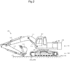
- FIG. 2 is an external view of a hydraulic excavator, which is an example of the construction machine.
- the hydraulic excavator includes a lower travel structure 100, an upper swing structure 101, and a front work device 102.
- the lower travel structure 100 includes left and right crawler travel devices 103a, 103b and is driven by left and right travel motors 104a, 104b.
- the upper swing structure 101 is swingably mounted on the lower travel structure 100 and driven by a swing motor 105.
- the front work device 102 is elevatably mounted on the front of the upper swing structure 101.
- the upper swing structure 101 includes an engine room 106, a cabin 107, and a counterweight 108.
- the engine 1 is disposed in the engine room 106.
- the front work device 102 is an articulated structure having a boom 111, an arm 112, and a bucket 113.
- the boom 111 pivots in an up-down direction when a boom cylinder 114 expands or contracts.
- the arm 112 pivots in the up-down direction and in a front-rear direction when an arm cylinder 115 expands or contracts.
- the bucket 113 pivots in the up-down direction and in the front-rear direction when a bucket cylinder 116 expands or contracts.
- the actuator 4 shown in FIG. 1 represents a plurality of actuators such as the swing motor 105, the arm cylinder 115, the boom cylinder 114, the bucket cylinder 116, and the travel motors 104a, 104b.
- the construction machine may be a wheel loader or a wheel hydraulic excavator.
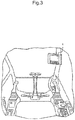
- FIG. 3 is a partially enlarged perspective view illustrating the inside of the cabin 107.
- the monitor device 6 is disposed at such a position that it can easily be viewed by an operator in the cabin 107 of the hydraulic excavator.
- the monitor device 6 primary displays basic vehicle body information about the hydraulic excavator such as the remaining amount of fuel and the temperature of cooling water.
- the monitor device 6 includes the display screen 6a and the operating switch 6b and is controlled by the monitor controller 13.
- the operating switch 6b is disposed below the display screen 6a. When the operating switch 6b is manipulated, the monitor device 6 selectively displays vehicle body information including the basic vehicle body information.
- the display screen 6a and the operating switch 6b also function as an interface. More specifically, the operator can perform various setup operations concerning the vehicle body by manipulating the operating switch 6b while viewing the display screen 6a.
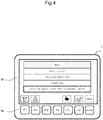
- FIG. 4 shows an example of a menu screen that appears on the display screen 6a.
- Pressing a menu key of the operating switch 6b causes the display screen 6a to switch from a basic vehicle body information screen (not shown) to the menu screen.
- the menu screen shows a plurality of menu options, namely, monitoring, troubleshooting, vehicle body information download, and vehicle body component replacement setup. "Down”, “Up” “Decision” (finger), “Return”, and “Menu” icons are respectively displayed at positions corresponding to the F1 key, F2 key, F5 key, F6 key, and menu key of the operating switch 6b.
- the options on the menu screen can be selected by moving a cursor (a thick outline in the figure) up or down and pressing the "Decision" key.
- the description of the options for monitoring, troubleshooting, and vehicle body information download is omitted.
- the vehicle body controller 11 includes an engine revolution speed/pump torque setting change function section 11a as one of its functions.
- the monitor controller 13 includes a component selection screen/component state selection screen display function section 13a as one of its functions.
- the information processing controller 14 stores an engine revolution speed/pump torque setting change table 14a as one item of information.
- FIG. 5 is a conceptual diagram illustrating the tree structure of screens that are displayed on the display screen 6a by the component selection screen/component state selection screen display function section 13a.
- the component selection screen/component state selection screen display function section 13a displays a component selection screen (see FIG. 6 ), a front state selection screen (see FIG. 7 ), a counterweight state selection screen (see FIG. 8 ), a hydraulic fluid state selection screen (see FIG. 9 ), and a conduit state selection screen (see FIG. 10 ).
- FIG. 6 shows an example of the component selection screen, which appears on the display screen 6a.
- the display screen 6a switches to the component selection screen.
- the component selection screen shows a plurality of options, namely, front, counterweight, hydraulic fluid, and conduit. When a certain option is selected, the associated component is selected.
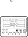
- FIG. 7 shows an example of the front state selection screen.
- the display screen 6a switches to the front state selection screen.
- the front state selection screen shows a plurality of options, namely, standard front, reinforced front, lightweight front.
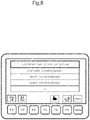
- FIG. 8 shows an example of the counterweight state selection screen.
- the display screen 6a switches to the counterweight state selection screen.
- the counterweight state selection screen shows a plurality of options, namely, standard counterweight, heavy counterweight, and light counterweight.
- FIG. 9 shows an example of the hydraulic fluid state selection screen.
- the display screen 6a switches to the hydraulic fluid state selection screen.
- the hydraulic fluid state selection screen shows a plurality of options, namely, standard hydraulic fluid and fuel-efficient hydraulic fluid.
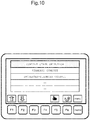
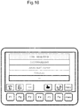
- FIG. 10 shows an example of the conduit state selection screen.
- the display screen 6a switches to the hydraulic fluid state selection screen.
- the conduit state selection screen shows a plurality of options, namely, standard conduit and increased-diameter conduit.
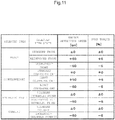
- FIG. 11 shows an example of the engine revolution speed/pump torque setting change table 14a. This table is organized with respect to various selected components and various selected component states in order to show how the engine revolution speed and the pump torque will be increased or decreased from their standard values (details will be given later).
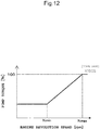
- FIG. 12 is a diagram illustrating an exemplary relationship between the engine revolution speed and pump torque that shows when all components, namely, the front, counterweight, hydraulic fluid, and conduit, are in their standard states (standard front, standard counterweight, standard hydraulic fluid, and standard conduit).
- Nmin a minimum pump torque is maintained.
- Nmin the pump torque increases with an increase in the engine revolution speed.
- Nmax a maximum pump torque is maintained.
- FIG. 12 indicates that the value of the maximum pump torque is 100%.
- the engine revolution speed/pump torque setting change function section 11a accesses a portion of the engine revolution speed/pump torque setting change table 14a that relates to a selected component (hydraulic fluid) and a selected component state (fuel-efficient hydraulic fluid), reads an engine revolution speed increase/decrease (-50 rpm) from the standard value and a pump torque increase/decrease (-5%) from the standard value, and changes the setting of the engine revolution speed and the setting of the pump torque.
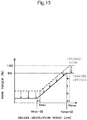
- FIG. 13 is a diagram illustrating an exemplary relationship between the engine revolution speed and pump torque that prevails after setting changes.
- the broken line indicative of the standard state which is shown in FIG. 13 , is shifted downward until the pump torque is decreased by 5%. Further, the minimum engine revolution speed Nmin and the maximum engine revolution speed Nmax are shifted leftward until they are decreased by 50 rpm.
- a change made to shift the broken line indicative of the standard state upward until the pump torque is increased by ⁇ ⁇ % and shift the minimum and maximum engine revolution speeds Nmin, Nmax rightward until they are increased by ⁇ N rpm is hereinafter indicated by an engine revolution speed increase of ⁇ N rpm and a pump torque increase of ⁇ %.
- the engine revolution speed/pump torque setting change function section 11a adds up the amounts of increase and decrease. If, for instance, the front is changed from a standard front to a reinforced front and the counterweight is changed from a standard counterweight to a heavy counterweight, the engine revolution speed/pump torque setting change function section 11a accesses a portion of the engine revolution speed/pump torque setting change table 14a that relates to a selected component (front) and a selected component state (reinforced front), reads an engine revolution speed increase/decrease (+50 rpm) from the standard value and a pump torque increase/decrease (+5%) from the standard value, accesses a portion of the engine revolution speed/pump torque setting change table 14a that relates to another selected component (counterweight) and another selected component state (heavy counterweight), reads an engine revolution speed increase/decrease (+50 rpm) from the standard value and a pump torque increase/decrease (+50 rpm) from the standard value and a pump torque increase/decrease (+50 rpm) from
- the display screen 6a and the operating switch 6b, which are included in the monitor device 6, the component selection screen/component state selection screen display function section 13a, and the screens shown in FIGS. 6 to 10 constitute component state selection means for selecting one of a plurality of component states.
- the engine revolution speed/pump torque setting change table 14a and the engine revolution speed/pump torque setting change function section 11a constitute engine revolution speed/pump torque setting change means for changing the setting of the engine revolution speed and the setting of the pump torque in accordance with a selected component state.
- a standard model (a model in which all components, namely, the front, counterweight, hydraulic fluid, and conduit, are in a standard state) of the hydraulic excavator is manufactured at a factory.
- a manufacturer's service technician replaces some components and changes some component states as needed to comply with a request of a customer and changes the settings of the engine revolution speed and pump torque in accordance with component replacements and component state changes.
- a leasing company purchases a large number of construction machines and leases them to a construction company or other customer.
- the leasing company When purchasing the hydraulic excavator, the leasing company generally purchases its standard model.
- a service technician of the leasing company replaces some components and changes some component states as needed to comply with a request of the customer and changes the settings of the engine revolution speed and pump torque in accordance with component replacements and component state changes.
- the service technician selects the vehicle body component replacement setup from the menu screen (see FIG. 4 ) to let the monitor device 6 display the component selection screen (see FIG. 6 ). Next, the service technician selects a displayed option corresponding to a replaced component to open a component state selection screen (see FIGS. 7 to 10 ), and selects an appropriate displayed component state.
- the engine revolution speed decreases by 50 rpm and the pump torque decreases by 5%. This reduces the engine output. Consequently, when the conduit is changed from the standard conduit to the increased-diameter conduit, the fuel efficiency can be improved while maintaining the operability equivalent to that of the standard model.
- the present embodiment changes the engine revolution speed and the pump torque in such a manner as to increase the engine output. This makes it possible to maintain the operability equivalent to that of the standard model.
- the present embodiment changes the engine revolution speed and the pump torque in such a manner as to reduce the engine output. This makes it possible to provide improved fuel efficiency while maintaining the operability equivalent to that of the standard model.
- the service technician can make the above-described setting changes with ease simply by selecting relevant options while viewing the monitor device 6.
- a second embodiment is obtained by adding some characteristic functions to the engine revolution speed/pump torque setting change function section 11a according to the first embodiment.
- a new component may be developed in addition to the components (component states) existing at the time of manufacture of the hydraulic excavator.
- the standard state is to be changed to a new component state, it is necessary to change the settings of the engine revolution speed and pump torque in accordance with the new component state.
- a second lightweight front which is lighter than the lightweight front, is developed will now be described as an example.
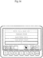
- FIG. 14 shows the front state selection screen for the addition of a component state.
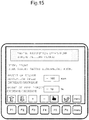
- FIG. 15 shows an engine revolution speed/pump torque setting change screen for the addition of a component state.
- the service technician selects the vehicle body component replacement setup from the menu screen (see FIG. 4 ) to let the monitor device 6 display the component selection screen (see FIG. 6 ).
- the service technician selects a displayed option (front) to open the front state selection screen (see FIG. 7 ).
- the service technician selects the added component state (second lightweight front) to open the engine revolution speed/pump torque setting change screen.
- the second lightweight front is lighter than the lightweight front, it can be expected that the fuel efficiency will further improve when the engine output is further reduced.
- the service technician manipulates the operating switch 6b (e.g., the F3 and F4 keys corresponding respectively to the "+" and "-" icons) to set an engine revolution speed increase/decrease (-100 rpm) from a standard value and a pump torque increase/decrease (-10%) from a standard value (see FIG. 15 ).
- the engine revolution speed/pump torque setting change function section 11a adds the engine revolution speed increase/decrease (-100 rpm) from the standard value and the pump torque increase/decrease (-10%) from the standard value to the engine revolution speed/pump torque setting change table 14a in accordance with the selected component (front) and with the selected component state (second lightweight front).
- the setting changes can be made with ease to reflect component state characteristics (e.g., the second lightweight front is lighter than the lightweight front).
- a plurality of component states can be selected to make changes, and the front, counterweight, hydraulic fluid, and conduit are exemplified as the components affecting the fuel consumption.
- the present invention is not limited to such an embodiment.
- Components can be added in accordance with the judgment of the customer or of the service technician. A case where an attachment is to be added as a component and a bucket (standard state) and a breaker are added as attachment states will now be described as an example.
- FIG. 16 shows the component selection screen for the addition of a component.
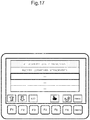
- FIG. 17 shows an attachment state selection screen for the addition of a component.
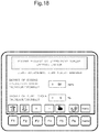
- FIG. 18 shows the engine revolution speed/pump torque setting change screen for the addition of a component.
- the service technician selects the vehicle body component replacement setup from the menu screen (see FIG. 4 ) to let the monitor device 6 display the component selection screen (see FIG. 6 ).
- the service technician moves the cursor downward to a blank field in the component selection screen, the "Add" icon appears at a position corresponding to the F3 key of the operating switch 6b at the bottom of the screen (see FIG. 16 ).
- the service technician adds a component (attachment) to the blank field.
- the service technician selects the added component (attachment) to open the attachment state selection screen (see FIG. 17 ).
- the service technician sets a bucket as the standard state of the attachment.
- the subsequent operations are the same as those described in conjunction with the addition of a component state.
- the service technician moves the cursor downward to a blank field in the attachment state selection screen and adds a component state (breaker) to the blank field.
- the service technician selects the added component state (breaker) to open the engine revolution speed/pump torque setting change screen.
- setup needs to be performed so as to increase the engine output.
- the service technician manipulates the operating switch 6b (the F3 and F4 keys corresponding respectively to the "+” and "-” icons) to set an engine revolution speed increase/decrease (+50 rpm) from a standard value and a pump torque increase/decrease (+5%) from a standard value (see FIG. 18 ).
- the engine revolution speed/pump torque setting change function section 11a adds an engine revolution speed increase/decrease ( ⁇ 0 rpm) from the standard value and a pump torque increase/decrease ( ⁇ 0%) from the standard value to the engine revolution speed/pump torque setting change table 14a in relation to the selected component (attachment) and the selected component state (bucket (standard state)), and adds an engine revolution speed increase/decrease (+50 rpm) from the standard value and a pump torque increase/decrease (+5%) from the standard value to the engine revolution speed/pump torque setting change table 14a in relation to the selected component (attachment) and the selected component state (breaker).
- Components and component states can be deleted as needed.
- a case where an added component (attachment) is to be deleted will now be described as an example.
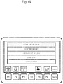
- FIG. 19 shows the component selection screen for the deletion of a component.
- the service technician selects the vehicle body component replacement setup from the menu screen (see FIG. 4 ) to let the monitor device 6 display the component selection screen (see FIG. 6 ).
- the service technician moves the cursor downward to a displayed component (attachment)
- a "Delete” icon appears at a position corresponding to the F3 key of the operating switch 6b at the bottom of the screen (see FIG. 19 ).
- the service technician manipulates the operating switch 6b to delete the displayed component (attachment).
- the engine revolution speed/pump torque setting change function section 11a deletes an engine revolution speed increase/decrease ( ⁇ 0 rpm) from the standard value and a pump torque increase/decrease ( ⁇ 0%) from the standard value, which relate to the selected component (attachment) and the selected component state (bucket (standard state)), from the engine revolution speed/pump torque setting change table 14a, and deletes an engine revolution speed increase/decrease (+50 rpm) from the standard value and a pump torque increase/decrease (+5%) from the standard value, which relate to the selected component (attachment) and the selected component state (breaker), from the engine revolution speed/pump torque setting change table 14a.
- Engine revolution speed and pump torque setting changes can be corrected as needed. A case where the engine revolution speed and pump torque setting changes for a selected breaker are to be corrected will now be described.
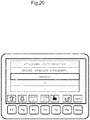
- FIG. 20 shows the attachment state selection screen for the correction of setting changes.
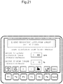
- FIG. 21 shows the engine revolution speed/pump torque setting change screen for the correction of setting changes.
- the service technician selects the vehicle body component replacement setup from the menu screen (see FIG. 4 ) to let the monitor device 6 display the component selection screen, selects a displayed component (attachment) (see FIG. 19 ) to open the attachment state selection screen.
- a displayed component state breaker
- the "Delete” icon and a "Correct” icon appear at positions corresponding respectively to the F3 and F4 keys of the operating switch 6b at the bottom of the screen (see FIG. 20 ).
- the service technician manipulates the operating switch 6b to open the engine revolution speed/pump torque setting change screen (see FIG. 18 ) for the purpose of correcting the displayed component (breaker).
- This screen shows the previously selected engine revolution speed increase/decrease (+50 rpm) from the standard value and the previously selected pump torque increase/decrease (+5%) from the standard value.
- the service technician manipulates the operating switch 6b to set an engine revolution speed increase/decrease (+100 rpm) from the standard value and a pump torque increase/decrease (+10%) from the standard value (see FIG. 21 ).
- the engine revolution speed/pump torque setting change function section 11a makes a correction to switch from the engine revolution speed increase/decrease (+50 rpm) from the standard value and the pump torque increase/decrease (+5%) from the standard value, which relate to the previous settings (selected component (attachment) and selected component state (breaker)) in the engine revolution speed/pump torque setting change table 14a, to the engine revolution speed increase/decrease (+100 rpm) from the standard value and the pump torque increase/decrease (+10%) from the standard value.
- the engine revolution speed/pump torque setting change function section 11a adds up the amounts of increase and decrease when a plurality of components are replaced. If, for instance, the front is changed from the standard front to the lightweight front, the counterweight is changed from the standard counterweight to the light counterweight, the hydraulic fluid is changed from the standard hydraulic fluid to the fuel-efficient hydraulic fluid, and the conduit is changed from the standard conduit to the increased-diameter conduit, the engine revolution speed/pump torque setting change function section 11a reads the engine revolution speed increase/decrease (-50 rpm) from the standard value and the pump torque increase/decrease (-5%) from the standard value, which relate to the selected component (front) and the selected component state (lightweight front), reads the engine revolution speed increase/decrease (-50 rpm) from the standard value and the pump torque increase/decrease (-5%) from the standard value, which relate to the selected component (counterweight) and the selected component state (light counterweight), reads the engine revolution speed increase/decrease (-50 rpm) from the standard value and
- the above problem may be addressed by setting upper and lower limits to avoid an excessive increase or decrease in the engine revolution speed and in the pump torque.
- FIG. 22 is a diagram illustrating the upper and lower limits for an increase and decrease in the engine revolution speed and in the pump torque. This figure is to be read in the same manner as FIGS. 12 and 13 . It is assumed, for example, that the upper limit represents an engine revolution speed increase of 100 rpm and a pump torque increase of 10%, and that the lower limit represents an engine revolution speed decrease of 100 rpm and a pump torque decrease of 10%.
- the engine revolution speed/pump torque setting change function section 11a makes changes so as to decrease the engine revolution speed by 100 rpm and decrease the pump torque by 10%. This makes it possible to avoid an excessive decrease in the engine output and maintain the operability.
- the engine revolution speed/pump torque setting change function section 11a makes changes so as to increase the engine revolution speed by 100 rpm and increase the pump torque by 10%. This makes it possible to avoid an excessive increase in the engine output and suppress the degradation of fuel efficiency.
Landscapes
- Engineering & Computer Science (AREA)
- General Engineering & Computer Science (AREA)
- Mining & Mineral Resources (AREA)
- Civil Engineering (AREA)
- Structural Engineering (AREA)
- Mechanical Engineering (AREA)
- Chemical & Material Sciences (AREA)
- Fluid Mechanics (AREA)
- Physics & Mathematics (AREA)
- Analytical Chemistry (AREA)
- Combustion & Propulsion (AREA)
- Operation Control Of Excavators (AREA)
- Control Of Vehicle Engines Or Engines For Specific Uses (AREA)
- Component Parts Of Construction Machinery (AREA)
Description
- The present invention relates to a control system for controlling an engine, a pump, and other components of a hydraulic excavator or other construction machine. More specifically, the present invention relates to a construction machine control system that is capable of changing an engine revolution speed setting and a pump torque setting. A control system as described in the preamble portion of
patent claim 1 has been known fromEP 0 989 242 A1 - A construction machine such as a hydraulic excavator generally includes a diesel engine. The diesel engine drives a hydraulic pump of a variable displacement type. A hydraulic fluid discharged from the hydraulic pump drives a plurality of hydraulic actuators to perform necessary operations. The engine includes a fuel injection device. The fuel injection device controls a fuel injection amount, thereby controlling an engine revolution speed and an output torque.
- Meanwhile, pump torque control is exercised over the hydraulic pump, which is rotationally driven by the engine, in order to prevent the engine from being excessively loaded. The pump torque control is exercised to prevent the maximum torque of the hydraulic pump from exceeding a setting by reducing the displacement volume of the hydraulic pump in accordance with an increase in the load pressure of the hydraulic pump.
- A predetermined revolution speed is basically selected for the engine by using an engine control dial. Besides, the revolution speed of the engine is controlled depending on the situation. An appropriate pump toque is then set in accordance with such revolution speed control.
- Optimizing the engine revolution speed setting and the pump torque setting makes it possible to provide improved fuel efficiency while maintaining the operability of the hydraulic excavator.
- A control device for controlling an engine and a pump of a construction machine is disclosed, for instance, in
JP 8-093520 A - The control device (control system) is a construction machine control device that controls the engine revolution speed by displacing the rack of an all-speed governor to increase or decrease the fuel injection amount, uses the engine to drive the pump, and controls the torque of the pump with a torque setup regulator. The control device includes a controller that detects the amount of displacement with a rack sensor and calculates an effective engine load factor by performing a stabilization process on the displacement amount of the rack. Further, work modes for multiple stages, which depend on the combinations of the engine revolution speed and pump torque, are set in the controller so as to control an engine revolution speed setting device and a torque setup regulator in accordance with a work mode designated by the controller. Furthermore, intermediate work modes included in the multiple stage work modes are provided with a region for switching to a next-stage work mode, a stabilized region, and a region for switching to a previous-stage work mode. Moreover, a highest-stage work mode is provided with a stabilized region and a region for switching to a previous-stage work mode. A lowest-stage work mode is provided with a region for switching to a next-stage work mode and a stabilized region. In addition, a switching region of each work mode has a portion that overlaps with a stabilized region in the next or previous stage work mode designated by the switching region. Meanwhile, when the effective engine load factor is above a predetermined value and a switching region in a certain work mode persists for a period not shorter than a predetermined period of time, control is exercised to switch to the next or previous stage work mode designated by the switching region.
- ........
EP 0 989 242 A1 - When a product is manufactured at a factory, a standard model formed of standard components (e.g., a front device) is mass-produced. However, when the product is to be shipped out of the factory, some components may be replaced as needed to meet the request of a customer.
- Further, in recent years, it is frequent that a leasing company purchases a large number of construction machines and leases them to a construction company or other customer. When purchasing the construction machines, the leasing company generally purchases standard models. However, when leasing the construction machines to the customer, the leasing company sometimes replaces some components of the construction machines as needed to meet the request of the customer.
- Prior-art control systems are designed on the assumption that they will be used with standard models of construction machines. Therefore, if some components of a construction machine, particularly, components affecting the fuel consumption, are replaced, desired effects may not be obtained.
- Further, when engine revolution speed and pump torque settings are to be changed in accordance with component replacements, a high level of technical expertise is required to obtain desired effects.
- An object of the present invention is to provide a construction machine control system that is not only capable of providing improved fuel efficiency without sacrificing the operability of a construction machine by changing the setting of an engine revolution speed and the setting of a pump torque in accordance with a component targeted for replacement when a certain component, particularly, a component affecting the fuel consumption, is replaced, but also capable of changing such settings with ease.
- The above object is accomplished, according to an aspect of the present invention, with a control system having the features of
claim 1. - Dependent claims are directed on features of preferred embodiments of the invention.
- The present invention makes it possible to provide improved fuel efficiency without sacrificing the operability of a construction machine by changing the setting of an engine revolution speed and the setting of a pump torque in accordance with a component targeted for replacement when a certain component, particularly, a component affecting the fuel consumption, is replaced. The present invention also makes it possible to change such settings with ease.
-
-
FIG. 1 is a diagram illustrating the overall configuration of a control system. -
FIG. 2 is an external view of a hydraulic excavator. -
FIG. 3 is a partially enlarged perspective view illustrating the inside of acabin 107. -
FIG. 4 shows an example of a menu screen. -
FIG. 5 is a conceptual diagram illustrating the tree structure of screens. -
FIG. 6 shows an example of a component selection screen. -
FIG. 7 shows an example of a front state selection screen. -
FIG. 8 shows an example of a counterweight state selection screen. -
FIG. 9 shows an example of a hydraulic fluid state selection screen. -
FIG. 10 shows an example of a conduit state selection screen. -
FIG. 11 shows an example of an engine revolution speed/pump torque setting change table. -
FIG. 12 is a diagram illustrating an exemplary relationship between the engine revolution speed and pump torque of a standard model. -
FIG. 13 is a diagram illustrating an exemplary relationship between the engine revolution speed and pump torque that prevails after setting changes. -
FIG. 14 shows the front state selection screen for the addition of a component state. -
FIG. 15 shows an engine revolution speed/pump torque setting change screen for the addition of a component state. -
FIG. 16 shows the component selection screen for the addition of a component. -
FIG. 17 shows an attachment state selection screen for the addition of a component. -
FIG. 18 shows the engine revolution speed/pump torque setting change screen for the addition of a component. -
FIG. 19 shows the component selection screen for the deletion of a component. -
FIG. 20 shows the attachment state selection screen for the correction of setting changes. -
FIG. 21 shows the engine revolution speed/pump torque setting change screen for the correction of setting changes. -
FIG. 22 is a diagram illustrating the upper and lower limits for an increase and decrease in the engine revolution speed and in the pump torque. - A first embodiment of the present invention will now be described with reference to the accompanying drawings.
-
FIG. 1 is a diagram illustrating the overall configuration of a control system according to the first embodiment of the present invention. - A construction machine, such as a hydraulic excavator, includes an
engine 1, ahydraulic pump 2, and anactuator 4. An output shaft of theengine 1 is connected to thehydraulic pump 2. Thehydraulic pump 2 is rotationally driven by theengine 1. A valve device 3 is connected to a discharge path (conduit 7) of thehydraulic pump 2. Hydraulic fluid 8 is supplied to theactuator 4 through the valve device to drive theactuator 4. Thehydraulic pump 2 includes aregulator 5 that controls the tilting (the tilting amount of a swash plate or the like, that is, the displacement volume or capacity) of thehydraulic pump 2 in accordance with the discharge pressure of thehydraulic pump 2 in order to prevent the torque consumed by thehydraulic pump 2 from exceeding its maximum absorption torque. - The control system controls the revolution speed of the
engine 1, the torque of the engine, and thehydraulic pump 2. The control system includes, for example, avehicle body controller 11, anengine controller 12, amonitor controller 13, and aninformation processing controller 14. These controllers are interconnected through acommunication line 15 to form a vehicle body network. - The
vehicle body controller 11 provides overall control of the vehicle body, including the control of a hydraulic drive system. For example, thevehicle body controller 11 controls the discharge pressure and discharge flow rate of thehydraulic pump 2 by controlling theregulator 5 of thehydraulic pump 2. - The
engine controller 12 inputs a revolution speed command signal of an engine control dial. In accordance with the revolution speed command signal and with an actual revolution speed detection signal from a revolution speed sensor, theengine controller 12 controls the revolution speed of theengine 1 and the engine torque. Separately from this control, theengine controller 12 controls the revolution speed as needed. - The
monitor controller 13 inputs various signals and various arithmetic processing results through thecommunication line 15 and sends a display signal to amonitor device 6, thereby causing adisplay screen 6a to display information included in the input signals. Themonitor controller 13 also inputs a command signal generated from anoperating switch 6b, which acts as a user interface. - The
information processing controller 14 collects and records information transmitted from thevehicle body controller 11, theengine controller 12, themonitor controller 13, and various sensors (not shown). -
FIG. 2 is an external view of a hydraulic excavator, which is an example of the construction machine. The hydraulic excavator includes alower travel structure 100, anupper swing structure 101, and afront work device 102. Thelower travel structure 100 includes left and rightcrawler travel devices right travel motors upper swing structure 101 is swingably mounted on thelower travel structure 100 and driven by aswing motor 105. Thefront work device 102 is elevatably mounted on the front of theupper swing structure 101. Theupper swing structure 101 includes anengine room 106, acabin 107, and acounterweight 108. Theengine 1 is disposed in theengine room 106. - The
front work device 102 is an articulated structure having aboom 111, anarm 112, and abucket 113. Theboom 111 pivots in an up-down direction when aboom cylinder 114 expands or contracts. Thearm 112 pivots in the up-down direction and in a front-rear direction when anarm cylinder 115 expands or contracts. Thebucket 113 pivots in the up-down direction and in the front-rear direction when abucket cylinder 116 expands or contracts. - The
actuator 4 shown inFIG. 1 represents a plurality of actuators such as theswing motor 105, thearm cylinder 115, theboom cylinder 114, thebucket cylinder 116, and thetravel motors - The construction machine may be a wheel loader or a wheel hydraulic excavator.
-
FIG. 3 is a partially enlarged perspective view illustrating the inside of thecabin 107. - The
monitor device 6 is disposed at such a position that it can easily be viewed by an operator in thecabin 107 of the hydraulic excavator. Themonitor device 6 primary displays basic vehicle body information about the hydraulic excavator such as the remaining amount of fuel and the temperature of cooling water. Themonitor device 6 includes thedisplay screen 6a and theoperating switch 6b and is controlled by themonitor controller 13. Theoperating switch 6b is disposed below thedisplay screen 6a. When theoperating switch 6b is manipulated, themonitor device 6 selectively displays vehicle body information including the basic vehicle body information. Thedisplay screen 6a and theoperating switch 6b also function as an interface. More specifically, the operator can perform various setup operations concerning the vehicle body by manipulating theoperating switch 6b while viewing thedisplay screen 6a. -
FIG. 4 shows an example of a menu screen that appears on thedisplay screen 6a. Pressing a menu key of theoperating switch 6b causes thedisplay screen 6a to switch from a basic vehicle body information screen (not shown) to the menu screen. The menu screen shows a plurality of menu options, namely, monitoring, troubleshooting, vehicle body information download, and vehicle body component replacement setup. "Down", "Up" "Decision" (finger), "Return", and "Menu" icons are respectively displayed at positions corresponding to the F1 key, F2 key, F5 key, F6 key, and menu key of theoperating switch 6b. The options on the menu screen can be selected by moving a cursor (a thick outline in the figure) up or down and pressing the "Decision" key. The description of the options for monitoring, troubleshooting, and vehicle body information download is omitted. - Returning to
FIG. 1 , the characteristic configuration of the present embodiment will be described. - The
vehicle body controller 11 includes an engine revolution speed/pump torque settingchange function section 11a as one of its functions. Themonitor controller 13 includes a component selection screen/component state selection screendisplay function section 13a as one of its functions. Theinformation processing controller 14 stores an engine revolution speed/pump torque setting change table 14a as one item of information. -
FIG. 5 is a conceptual diagram illustrating the tree structure of screens that are displayed on thedisplay screen 6a by the component selection screen/component state selection screendisplay function section 13a. The component selection screen/component state selection screendisplay function section 13a displays a component selection screen (seeFIG. 6 ), a front state selection screen (seeFIG. 7 ), a counterweight state selection screen (seeFIG. 8 ), a hydraulic fluid state selection screen (seeFIG. 9 ), and a conduit state selection screen (seeFIG. 10 ). -
FIG. 6 shows an example of the component selection screen, which appears on thedisplay screen 6a. When the vehicle body component replacement setup is selected from the menu screen (seeFIG. 4 ), thedisplay screen 6a switches to the component selection screen. The component selection screen shows a plurality of options, namely, front, counterweight, hydraulic fluid, and conduit. When a certain option is selected, the associated component is selected. -
FIG. 7 shows an example of the front state selection screen. When the front is chosen as a selected option from the component selection screen (seeFIG. 6 ), thedisplay screen 6a switches to the front state selection screen. The front state selection screen shows a plurality of options, namely, standard front, reinforced front, lightweight front. -
FIG. 8 shows an example of the counterweight state selection screen. When the counterweight is chosen as a selected option from the component selection screen (seeFIG. 6 ), thedisplay screen 6a switches to the counterweight state selection screen. The counterweight state selection screen shows a plurality of options, namely, standard counterweight, heavy counterweight, and light counterweight. -
FIG. 9 shows an example of the hydraulic fluid state selection screen. When the hydraulic fluid is chosen as a selected option from the component selection screen (seeFIG. 6 ), thedisplay screen 6a switches to the hydraulic fluid state selection screen. The hydraulic fluid state selection screen shows a plurality of options, namely, standard hydraulic fluid and fuel-efficient hydraulic fluid. -
FIG. 10 shows an example of the conduit state selection screen. When the conduit is chosen as a selected option from the component selection screen (seeFIG. 6 ), thedisplay screen 6a switches to the hydraulic fluid state selection screen. The conduit state selection screen shows a plurality of options, namely, standard conduit and increased-diameter conduit. - When specific options are selected from the component state selection screens (see
FIGS. 7 to 10 ), a component state is selected. -
FIG. 11 shows an example of the engine revolution speed/pump torque setting change table 14a. This table is organized with respect to various selected components and various selected component states in order to show how the engine revolution speed and the pump torque will be increased or decreased from their standard values (details will be given later). - Main functions of the engine revolution speed/pump torque setting
change function section 11a will now be described with reference toFIGS. 12 and13 . -
FIG. 12 is a diagram illustrating an exemplary relationship between the engine revolution speed and pump torque that shows when all components, namely, the front, counterweight, hydraulic fluid, and conduit, are in their standard states (standard front, standard counterweight, standard hydraulic fluid, and standard conduit). When the engine revolution speed is lower than Nmin, a minimum pump torque is maintained. When the engine revolution speed is not lower than Nmin, the pump torque increases with an increase in the engine revolution speed. When the engine revolution speed is not lower than Nmax, a maximum pump torque is maintained.FIG. 12 indicates that the value of the maximum pump torque is 100%. - A case where the hydraulic fluid is changed from a standard hydraulic fluid to a fuel-efficient hydraulic fluid will now be described as an example. The engine revolution speed/pump torque setting
change function section 11a accesses a portion of the engine revolution speed/pump torque setting change table 14a that relates to a selected component (hydraulic fluid) and a selected component state (fuel-efficient hydraulic fluid), reads an engine revolution speed increase/decrease (-50 rpm) from the standard value and a pump torque increase/decrease (-5%) from the standard value, and changes the setting of the engine revolution speed and the setting of the pump torque. -
FIG. 13 is a diagram illustrating an exemplary relationship between the engine revolution speed and pump torque that prevails after setting changes. The broken line indicative of the standard state, which is shown inFIG. 13 , is shifted downward until the pump torque is decreased by 5%. Further, the minimum engine revolution speed Nmin and the maximum engine revolution speed Nmax are shifted leftward until they are decreased by 50 rpm. - For brevity of explanation, this document assumes that the shift from the broken line in
FIG. 13 to the solid line in the same figure is indicated by an engine speed decrease of 50 rpm and a pump torque decrease of 5%. A change made to shift the broken line indicative of the standard state downward until the pump torque is decreased by δ×% and shift the minimum and maximum engine revolution speeds Nmin, Nmax leftward until they are decreased by δN rpm is hereinafter indicated by an engine revolution speed decrease of δN rpm and a pump torque decrease of δ×%. Further, a change made to shift the broken line indicative of the standard state upward until the pump torque is increased by δר% and shift the minimum and maximum engine revolution speeds Nmin, Nmax rightward until they are increased by δN rpm is hereinafter indicated by an engine revolution speed increase of δN rpm and a pump torque increase of δ×%. - The above-described example assumes that only the hydraulic fluid is replaced. If a plurality of components are replaced, the engine revolution speed/pump torque setting
change function section 11a adds up the amounts of increase and decrease. If, for instance, the front is changed from a standard front to a reinforced front and the counterweight is changed from a standard counterweight to a heavy counterweight, the engine revolution speed/pump torque settingchange function section 11a accesses a portion of the engine revolution speed/pump torque setting change table 14a that relates to a selected component (front) and a selected component state (reinforced front), reads an engine revolution speed increase/decrease (+50 rpm) from the standard value and a pump torque increase/decrease (+5%) from the standard value, accesses a portion of the engine revolution speed/pump torque setting change table 14a that relates to another selected component (counterweight) and another selected component state (heavy counterweight), reads an engine revolution speed increase/decrease (+50 rpm) from the standard value and a pump torque increase/decrease (+5%) from the standard value, adds up the read values, and makes changes by increasing the engine revolution speed by 100 rpm and increasing the pump torque by 10%. - The
display screen 6a and theoperating switch 6b, which are included in themonitor device 6, the component selection screen/component state selection screendisplay function section 13a, and the screens shown inFIGS. 6 to 10 constitute component state selection means for selecting one of a plurality of component states. - The engine revolution speed/pump torque setting change table 14a and the engine revolution speed/pump torque setting
change function section 11a constitute engine revolution speed/pump torque setting change means for changing the setting of the engine revolution speed and the setting of the pump torque in accordance with a selected component state. - A standard model (a model in which all components, namely, the front, counterweight, hydraulic fluid, and conduit, are in a standard state) of the hydraulic excavator is manufactured at a factory. However, when the hydraulic excavator is to be shipped out of the factory, a manufacturer's service technician replaces some components and changes some component states as needed to comply with a request of a customer and changes the settings of the engine revolution speed and pump torque in accordance with component replacements and component state changes.
- Further, in recent years, it is frequent that a leasing company purchases a large number of construction machines and leases them to a construction company or other customer. When purchasing the hydraulic excavator, the leasing company generally purchases its standard model. Meanwhile, a service technician of the leasing company replaces some components and changes some component states as needed to comply with a request of the customer and changes the settings of the engine revolution speed and pump torque in accordance with component replacements and component state changes.
- The service technician selects the vehicle body component replacement setup from the menu screen (see
FIG. 4 ) to let themonitor device 6 display the component selection screen (seeFIG. 6 ). Next, the service technician selects a displayed option corresponding to a replaced component to open a component state selection screen (seeFIGS. 7 to 10 ), and selects an appropriate displayed component state. - A case where the front is changed from the standard front to the reinforced front will now be described. As the reinforced front is heavier than the standard front, the operability of the hydraulic excavator deteriorates (e.g., the speed of boom raising decreases) when control based on the standard model is exercised.
- When the service technician selects a displayed component state (reinforced front), the engine revolution speed increases by 50 rpm and the pump torque increases by 5% (refer to the description given with reference to
FIG. 13 for the expressions of changes). This increases an engine output. Consequently, the operability equivalent to that of the standard model can be maintained even when the front is changed from the standard front to the reinforced front. - A case where the front is changed from the standard front to the lightweight front will now be described. As the lightweight front is lighter than the standard front, for example, the speed of boom raising increases when control based on the standard model is exercised. However, the speed need not be increased beyond the speed of the standard model. Instead, it is preferred that improved fuel efficiency be provided.
- When the service technician selects a displayed component state (lightweight front), the engine revolution speed decreases by 50 rpm and the pump torque decreases by 5%. This reduces the engine output. Consequently, when the front is changed from the standard front to the lightweight front, the fuel efficiency can be improved while maintaining the operability equivalent to that of the standard model.
- A case where the counterweight is changed from the standard counterweight to the heavy counterweight will now be described. As the heavy counterweight is heavier than the standard counterweight, the operability deteriorates (e.g., the speed of swinging decreases) when control based on the standard model is exercised.
- When the service technician selects a displayed component state (heavy counterweight), the engine revolution speed increases by 50 rpm and the pump torque increases by 5%. This increases the engine output. Consequently, the operability equivalent to that of the standard model can be maintained even when the counterweight is changed from the standard counterweight to the heavy counterweight.
- A case where the counterweight is changed from the standard counterweight to the light counterweight will now be described. As the light counterweight is lighter than the standard counterweight, for example, the speed of swinging increases when control based on the standard model is exercised. However, the speed need not be increased beyond the speed of the standard model. Instead, it is preferred that improved fuel efficiency be provided.
- When the service technician selects a displayed component state (light counterweight), the engine revolution speed decreases by 50 rpm and the pump torque decreases by 5%. This reduces the engine output. Consequently, when the counterweight is changed from the standard counterweight to the light counterweight, the fuel efficiency can be improved while maintaining the operability equivalent to that of the standard model.
- A case where the hydraulic fluid is changed from the standard hydraulic fluid to the fuel-efficient hydraulic fluid will now be described. As the fuel-efficient hydraulic fluid has a lower viscosity than the standard hydraulic fluid, a pressure loss decreases. Therefore, when control based on the standard model is exercised, the speeds of various actuators increase. However, the speed need not be increased beyond the speed of the standard model. Instead, it is preferred that improved fuel efficiency be provided.
- When the service technician selects a displayed component state (fuel-efficient hydraulic fluid), the engine revolution speed decreases by 50 rpm and the pump torque decreases by 5%. This reduces the engine output. Consequently, when the hydraulic fluid is changed from the standard hydraulic fluid to the fuel-efficient hydraulic fluid, the fuel efficiency can be improved while maintaining the operability equivalent to that of the standard model.
- A case where the conduit is changed from the standard conduit to the increased-diameter conduit will now be described. As the increased-diameter conduit has a larger cross-sectional area than the standard conduit, the pressure loss decreases. Therefore, when control based on the standard model is exercised, the speeds of various actuators increase. However, the speeds need not be increased beyond the speeds of the standard model. Instead, it is preferred that improved fuel efficiency be provided.
- When the service technician selects a displayed component state (increased-diameter conduit), the engine revolution speed decreases by 50 rpm and the pump torque decreases by 5%. This reduces the engine output. Consequently, when the conduit is changed from the standard conduit to the increased-diameter conduit, the fuel efficiency can be improved while maintaining the operability equivalent to that of the standard model.
- Cases where the state of a certain component is changed from the standard model (in which all components are in the standard state) have been described above. The same holds true when a component is replaced to revert to the standard state. The service technician selects the vehicle body component replacement setup from the menu screen (see
FIG. 4 ) to let themonitor device 6 display the component selection screen (seeFIG. 6 ). Next, the service technician selects a displayed option corresponding to the replaced component to open a component state selection screen (seeFIGS. 7 to 10 ), and selects a displayed component state in the standard state (e.g., the standard front). This ensures that control based on the standard model is exercised. - As described above, when control based on the standard model is exercised in a situation where the speed of an actuator is decreased by component replacement, the present embodiment changes the engine revolution speed and the pump torque in such a manner as to increase the engine output. This makes it possible to maintain the operability equivalent to that of the standard model.
- When control based on the standard model is exercised in a situation where the speed of the actuator is increased by component replacement, the present embodiment changes the engine revolution speed and the pump torque in such a manner as to reduce the engine output. This makes it possible to provide improved fuel efficiency while maintaining the operability equivalent to that of the standard model.
- The service technician can make the above-described setting changes with ease simply by selecting relevant options while viewing the
monitor device 6. - A second embodiment is obtained by adding some characteristic functions to the engine revolution speed/pump torque setting
change function section 11a according to the first embodiment. - A new component (component state) may be developed in addition to the components (component states) existing at the time of manufacture of the hydraulic excavator. When the standard state is to be changed to a new component state, it is necessary to change the settings of the engine revolution speed and pump torque in accordance with the new component state. A case where a second lightweight front, which is lighter than the lightweight front, is developed will now be described as an example.
-
FIG. 14 shows the front state selection screen for the addition of a component state.FIG. 15 shows an engine revolution speed/pump torque setting change screen for the addition of a component state. - The service technician selects the vehicle body component replacement setup from the menu screen (see
FIG. 4 ) to let themonitor device 6 display the component selection screen (seeFIG. 6 ). Next, the service technician selects a displayed option (front) to open the front state selection screen (seeFIG. 7 ). - When the service technician moves the cursor downward to a blank field in the front state selection screen, an "Add" icon appears at a position corresponding to the F3 key of the
operating switch 6b at the bottom of the screen (seeFIG. 14 ). The service technician adds a component state (second lightweight front) to the blank field. - Further, the service technician selects the added component state (second lightweight front) to open the engine revolution speed/pump torque setting change screen. As the second lightweight front is lighter than the lightweight front, it can be expected that the fuel efficiency will further improve when the engine output is further reduced. For example, the service technician manipulates the
operating switch 6b (e.g., the F3 and F4 keys corresponding respectively to the "+" and "-" icons) to set an engine revolution speed increase/decrease (-100 rpm) from a standard value and a pump torque increase/decrease (-10%) from a standard value (seeFIG. 15 ). - The engine revolution speed/pump torque setting
change function section 11a adds the engine revolution speed increase/decrease (-100 rpm) from the standard value and the pump torque increase/decrease (-10%) from the standard value to the engine revolution speed/pump torque setting change table 14a in accordance with the selected component (front) and with the selected component state (second lightweight front). - As described above, even when a new component (component state) is developed, the setting changes can be made with ease to reflect component state characteristics (e.g., the second lightweight front is lighter than the lightweight front).
- Once a new component state is added, the subsequent operations to be performed are the same as those described in conjunction with the first embodiment.
- In the first embodiment, a plurality of component states can be selected to make changes, and the front, counterweight, hydraulic fluid, and conduit are exemplified as the components affecting the fuel consumption. However, the present invention is not limited to such an embodiment. Components can be added in accordance with the judgment of the customer or of the service technician. A case where an attachment is to be added as a component and a bucket (standard state) and a breaker are added as attachment states will now be described as an example.
-
FIG. 16 shows the component selection screen for the addition of a component.FIG. 17 shows an attachment state selection screen for the addition of a component.FIG. 18 shows the engine revolution speed/pump torque setting change screen for the addition of a component. - The service technician selects the vehicle body component replacement setup from the menu screen (see
FIG. 4 ) to let themonitor device 6 display the component selection screen (seeFIG. 6 ). When the service technician moves the cursor downward to a blank field in the component selection screen, the "Add" icon appears at a position corresponding to the F3 key of theoperating switch 6b at the bottom of the screen (seeFIG. 16 ). The service technician adds a component (attachment) to the blank field. - Further, the service technician selects the added component (attachment) to open the attachment state selection screen (see
FIG. 17 ). The service technician sets a bucket as the standard state of the attachment. The subsequent operations are the same as those described in conjunction with the addition of a component state. - More specifically, the service technician moves the cursor downward to a blank field in the attachment state selection screen and adds a component state (breaker) to the blank field.
- Further, the service technician selects the added component state (breaker) to open the engine revolution speed/pump torque setting change screen. When the bucket is to be replaced by the breaker, setup needs to be performed so as to increase the engine output. For example, the service technician manipulates the
operating switch 6b (the F3 and F4 keys corresponding respectively to the "+" and "-" icons) to set an engine revolution speed increase/decrease (+50 rpm) from a standard value and a pump torque increase/decrease (+5%) from a standard value (seeFIG. 18 ). - The engine revolution speed/pump torque setting
change function section 11a adds an engine revolution speed increase/decrease (±0 rpm) from the standard value and a pump torque increase/decrease (±0%) from the standard value to the engine revolution speed/pump torque setting change table 14a in relation to the selected component (attachment) and the selected component state (bucket (standard state)), and adds an engine revolution speed increase/decrease (+50 rpm) from the standard value and a pump torque increase/decrease (+5%) from the standard value to the engine revolution speed/pump torque setting change table 14a in relation to the selected component (attachment) and the selected component state (breaker). - As described above, even when a new component is to be added, relevant setting changes can be made with ease to reflect a component state and component state characteristics.
- Once a component is added, the subsequent operations to be performed are the same as those described in conjunction with the first embodiment.
- Components and component states can be deleted as needed. A case where an added component (attachment) is to be deleted will now be described as an example.
-
FIG. 19 shows the component selection screen for the deletion of a component. - The service technician selects the vehicle body component replacement setup from the menu screen (see
FIG. 4 ) to let themonitor device 6 display the component selection screen (seeFIG. 6 ). When the service technician moves the cursor downward to a displayed component (attachment), a "Delete" icon appears at a position corresponding to the F3 key of theoperating switch 6b at the bottom of the screen (seeFIG. 19 ). The service technician manipulates theoperating switch 6b to delete the displayed component (attachment). - The engine revolution speed/pump torque setting
change function section 11a deletes an engine revolution speed increase/decrease (±0 rpm) from the standard value and a pump torque increase/decrease (±0%) from the standard value, which relate to the selected component (attachment) and the selected component state (bucket (standard state)), from the engine revolution speed/pump torque setting change table 14a, and deletes an engine revolution speed increase/decrease (+50 rpm) from the standard value and a pump torque increase/decrease (+5%) from the standard value, which relate to the selected component (attachment) and the selected component state (breaker), from the engine revolution speed/pump torque setting change table 14a. - Engine revolution speed and pump torque setting changes can be corrected as needed. A case where the engine revolution speed and pump torque setting changes for a selected breaker are to be corrected will now be described.
-
FIG. 20 shows the attachment state selection screen for the correction of setting changes.FIG. 21 shows the engine revolution speed/pump torque setting change screen for the correction of setting changes. - The service technician selects the vehicle body component replacement setup from the menu screen (see
FIG. 4 ) to let themonitor device 6 display the component selection screen, selects a displayed component (attachment) (seeFIG. 19 ) to open the attachment state selection screen. When the service technician moves the cursor downward to a displayed component state (breaker), the "Delete" icon and a "Correct" icon appear at positions corresponding respectively to the F3 and F4 keys of theoperating switch 6b at the bottom of the screen (seeFIG. 20 ). The service technician manipulates theoperating switch 6b to open the engine revolution speed/pump torque setting change screen (seeFIG. 18 ) for the purpose of correcting the displayed component (breaker). This screen shows the previously selected engine revolution speed increase/decrease (+50 rpm) from the standard value and the previously selected pump torque increase/decrease (+5%) from the standard value. - If the operability of the breaker is poor at the previous settings, it is necessary to correct the settings in such a manner as to further increase the engine output. In such an instance, for example, the service technician manipulates the
operating switch 6b to set an engine revolution speed increase/decrease (+100 rpm) from the standard value and a pump torque increase/decrease (+10%) from the standard value (seeFIG. 21 ). - The engine revolution speed/pump torque setting
change function section 11a makes a correction to switch from the engine revolution speed increase/decrease (+50 rpm) from the standard value and the pump torque increase/decrease (+5%) from the standard value, which relate to the previous settings (selected component (attachment) and selected component state (breaker)) in the engine revolution speed/pump torque setting change table 14a, to the engine revolution speed increase/decrease (+100 rpm) from the standard value and the pump torque increase/decrease (+10%) from the standard value. - In the first embodiment, the engine revolution speed/pump torque setting
change function section 11a adds up the amounts of increase and decrease when a plurality of components are replaced. If, for instance, the front is changed from the standard front to the lightweight front, the counterweight is changed from the standard counterweight to the light counterweight, the hydraulic fluid is changed from the standard hydraulic fluid to the fuel-efficient hydraulic fluid, and the conduit is changed from the standard conduit to the increased-diameter conduit, the engine revolution speed/pump torque setting change function section 11a reads the engine revolution speed increase/decrease (-50 rpm) from the standard value and the pump torque increase/decrease (-5%) from the standard value, which relate to the selected component (front) and the selected component state (lightweight front), reads the engine revolution speed increase/decrease (-50 rpm) from the standard value and the pump torque increase/decrease (-5%) from the standard value, which relate to the selected component (counterweight) and the selected component state (light counterweight), reads the engine revolution speed increase/decrease (-50 rpm) from the standard value and the pump torque increase/decrease (-5%) from the standard value, which relate to the selected component (hydraulic fluid) and the selected component state (fuel-efficient hydraulic fluid), reads the engine revolution speed increase/decrease (-50 rpm) from the standard value and the pump torque increase/decrease (-5%) from the standard value, which relate to the selected component (conduit) and the selected component state (increased-diameter conduit), from the engine revolution speed/pump torque setting change table 14a, adds up the read values, and makes changes by decreasing the engine revolution speed by 200 rpm and decreasing the pump torque by 20%. - However, if the engine output is excessively reduced as mentioned above, the operability may not be maintained. Meanwhile, if components are replaced to increase the engine output by making changes to increase the engine revolution speed by 200 rpm and increase the pump torque by 20%, the fuel efficiency may excessively degrade.
- The above problem may be addressed by setting upper and lower limits to avoid an excessive increase or decrease in the engine revolution speed and in the pump torque.
-
FIG. 22 is a diagram illustrating the upper and lower limits for an increase and decrease in the engine revolution speed and in the pump torque. This figure is to be read in the same manner asFIGS. 12 and13 . It is assumed, for example, that the upper limit represents an engine revolution speed increase of 100 rpm and a pump torque increase of 10%, and that the lower limit represents an engine revolution speed decrease of 100 rpm and a pump torque decrease of 10%. - For example, even if the sum of the amounts of increase and decrease indicates an engine revolution speed decrease of 200 rpm and a pump torque decrease of 20%, the engine revolution speed/pump torque setting
change function section 11a makes changes so as to decrease the engine revolution speed by 100 rpm and decrease the pump torque by 10%. This makes it possible to avoid an excessive decrease in the engine output and maintain the operability. - On the other hand, even if, for example, the sum of the amounts of increase and decrease indicates an engine revolution speed increase of 200 rpm and a pump torque increase of 20%, the engine revolution speed/pump torque setting
change function section 11a makes changes so as to increase the engine revolution speed by 100 rpm and increase the pump torque by 10%. This makes it possible to avoid an excessive increase in the engine output and suppress the degradation of fuel efficiency. -
- 1... Diesel engine
- 2... Hydraulic pump
- 3... Valve device
- 4... Actuator
- 5... Regulator
- 6... Monitor device
- 6a... Display screen
- 6b... Operating switch
- 7... Conduit
- 8... Hydraulic fluid
- 11... Vehicle body controller
- 11a... Engine revolution speed/pump torque setting change function section
- 12... Engine controller
- 13... Monitor controller
- 13a... Component selection screen/component state selection screen display function section
- 14... Information processing controller
- 14a... Engine revolution speed/pump torque setting change table
- 15... Communication line
- 100... Lower travel structure
- 101... Upper swing structure
- 102... Front work device
- 103a, 103b... Crawler travel device
- 104a, 104b... Travel motor
- 105... Swing motor
- 106... Engine room
- 107... Cabin
- 111... Boom
- 112... Arm
- 113... Bucket
- 114... Boom cylinder
- 115... Arm cylinder
- 116... Bucket cylinder
Claims (7)
- A control system for a construction machine having a plurality of components including an engine (1), a hydraulic pump (2) driven by the engine (1), an actuator (4) driven by a hydraulic fluid discharged from the hydraulic pump (2), a member driven by the actuator (4), a front, a counterweight, hydraulic fluid and conduit, at least one of the components being selectively changeable from one component state to another, the control system comprising:component state selection means for selecting at least one of a plurality of component states; andengine revolution speed/pump torque setting change means (11a) for changing the setting of an engine revolution speed and the setting of a pump torque in accordance with the component state selected by the component state selection means,characterized in that the component state selection means can select the plurality of component states simultaneously, andthe engine revolution speed/pump torque setting change means changes the setting of amounts of increase and decrease of the engine revolution speed and amounts of increase and decrease of the pump torque so that a sum of the increase and decrease of the engine revolution speed and a sum of the increase and decrease of the pump torque corresponding to the selected respective component states do not exceed previously defined respective upper limits and respective lower limits when the plurality of component states is simultaneously selected by the component state selection means.
- The control system according to claim 1, wherein the component that is selectively changeable from one component state to another is a component affecting the fuel consumption of the construction machine.
- The control system according to claim 2, wherein the component affecting the fuel consumption of the construction machine is a component affecting the weight of a vehicle body.
- The control system according to claim 2, wherein the component affecting the fuel consumption of the construction machine is a component affecting the fluid resistance of the hydraulic fluid (8).
- The control system according to claim 4, wherein the component affecting the fluid resistance of the hydraulic fluid (8) is the hydraulic fluid (8).
- The control system according to claim 4, wherein the component affecting the fluid resistance of the hydraulic fluid (8) is a hydraulic fluid conduit (7).
- The control system according to claim 1, wherein the component state selection means includes a display screen (6a) of a monitor device (6).
Applications Claiming Priority (2)
| Application Number | Priority Date | Filing Date | Title |
|---|---|---|---|
| JP2011106572A JP5566333B2 (en) | 2011-05-11 | 2011-05-11 | Construction machine control system |
| PCT/JP2012/059405 WO2012153586A1 (en) | 2011-05-11 | 2012-04-05 | System for controlling construction machine |
Publications (3)
| Publication Number | Publication Date |
|---|---|
| EP2708662A1 EP2708662A1 (en) | 2014-03-19 |
| EP2708662A4 EP2708662A4 (en) | 2015-04-15 |
| EP2708662B1 true EP2708662B1 (en) | 2017-04-05 |
Family
ID=47139072
Family Applications (1)
| Application Number | Title | Priority Date | Filing Date |
|---|---|---|---|
| EP12782784.8A Not-in-force EP2708662B1 (en) | 2011-05-11 | 2012-04-05 | System for controlling construction machine |
Country Status (6)
| Country | Link |
|---|---|
| US (1) | US9260838B2 (en) |
| EP (1) | EP2708662B1 (en) |
| JP (1) | JP5566333B2 (en) |
| KR (1) | KR101911572B1 (en) |
| CN (1) | CN103534421B (en) |
| WO (1) | WO2012153586A1 (en) |
Families Citing this family (10)
| Publication number | Priority date | Publication date | Assignee | Title |
|---|---|---|---|---|
| KR102015141B1 (en) * | 2013-03-29 | 2019-08-27 | 두산인프라코어 주식회사 | Control system and method of Hydraulic Pump for Construction Machinery |
| JP5583872B1 (en) * | 2013-12-06 | 2014-09-03 | 株式会社小松製作所 | Excavator |
| US20160348341A1 (en) * | 2014-01-27 | 2016-12-01 | Volvo Construction Equipment Ab | Outrigger and dozer control using gui |
| US10208455B2 (en) * | 2016-03-17 | 2019-02-19 | Deere & Company | In-vehicle dynometer |
| JP6580618B2 (en) * | 2017-03-21 | 2019-09-25 | 日立建機株式会社 | Construction machinery |
| JP2019078132A (en) * | 2017-10-27 | 2019-05-23 | コベルコ建機株式会社 | Work machine |
| DE102018208500B4 (en) * | 2018-05-29 | 2022-11-17 | Moba Mobile Automation Ag | Operating device for a construction machine |
| CA3107441A1 (en) | 2018-07-25 | 2020-01-30 | Clark Equipment Company | Hydraulic oil temperature management for a power machine |
| EP3877235A4 (en) | 2018-11-09 | 2023-07-19 | Iocurrents, Inc. | Machine learning-based prediction, planning, and optimization of trip time, trip cost, and/or pollutant emission during navigation |
| KR20210103782A (en) * | 2020-02-14 | 2021-08-24 | 두산인프라코어 주식회사 | Control method for construction machinery and contorl system for construction machinery |
Family Cites Families (57)
| Publication number | Priority date | Publication date | Assignee | Title |
|---|---|---|---|---|
| JPH0657787A (en) * | 1992-08-06 | 1994-03-01 | Yutani Heavy Ind Ltd | Flow rate control device for crusher |
| US5850341A (en) * | 1994-06-30 | 1998-12-15 | Caterpillar Inc. | Method and apparatus for monitoring material removal using mobile machinery |
| JP3589710B2 (en) | 1994-09-28 | 2004-11-17 | 住友建機製造株式会社 | Engine and pump control devices for construction machinery |
| JP3609182B2 (en) * | 1996-01-08 | 2005-01-12 | 日立建機株式会社 | Hydraulic drive unit for construction machinery |
| JPH10237904A (en) * | 1997-02-25 | 1998-09-08 | Shin Caterpillar Mitsubishi Ltd | Method of controlling construction machinery and device thereof |
| JP3323791B2 (en) * | 1997-11-25 | 2002-09-09 | 新キャタピラー三菱株式会社 | Control device and control method for construction machine |
| US6923285B1 (en) * | 2000-02-01 | 2005-08-02 | Clark Equipment Company | Attachment control device |
| US6898502B2 (en) | 2000-03-31 | 2005-05-24 | Hitachi Construction Machinery Co., Ltd. | System for changing function of work machine and base station |
| JP4098955B2 (en) * | 2000-12-18 | 2008-06-11 | 日立建機株式会社 | Construction machine control equipment |
| US7048515B2 (en) * | 2001-06-21 | 2006-05-23 | Hitachi Construction Machinery Co., Ltd. | Hydraulic drive system and method using a fuel injection control unit |
| JP2004150304A (en) * | 2002-10-29 | 2004-05-27 | Komatsu Ltd | Controller of engine |
| WO2004040904A1 (en) * | 2002-10-29 | 2004-05-13 | Photonfocus Ag | Optoelectronic sensor |
| JP2004188326A (en) * | 2002-12-11 | 2004-07-08 | Hitachi Constr Mach Co Ltd | Self-traveling type crusher |
| US6925375B2 (en) * | 2003-03-20 | 2005-08-02 | Detroit Diesel Corporation | System and method for determining a parameter set for an engine controller module |
| US7588118B2 (en) * | 2003-05-07 | 2009-09-15 | Komatsu Ltd. | Work machine with engine control device |
| JP4484467B2 (en) * | 2003-08-01 | 2010-06-16 | 日立建機株式会社 | Traveling hydraulic working machine |
| CN100420840C (en) * | 2003-08-11 | 2008-09-24 | 株式会社小松制作所 | Hydraulic driving control device and hydraulic shovel with the control device |
| US7607296B2 (en) * | 2003-12-09 | 2009-10-27 | Komatsu Ltd. | Device and method of controlling hydraulic drive of construction machinery |
| JP4675320B2 (en) * | 2004-04-08 | 2011-04-20 | 株式会社小松製作所 | Hydraulic drive device for work machine |
| GB2429795B (en) * | 2004-05-07 | 2008-06-04 | Komatsu Mfg Co Ltd | Hydraulic drive apparatus of work machine |
| JP4270505B2 (en) * | 2004-08-11 | 2009-06-03 | 株式会社小松製作所 | Load control device for engine of work vehicle |
| US7400959B2 (en) * | 2004-08-27 | 2008-07-15 | Caterpillar Inc. | System for customizing responsiveness of a work machine |
| WO2006035589A1 (en) * | 2004-09-27 | 2006-04-06 | Hitachi Construction Machinery Co., Ltd. | Engine control device for working vehicle |
| JP4188902B2 (en) * | 2004-11-22 | 2008-12-03 | 日立建機株式会社 | Control equipment for hydraulic construction machinery |
| JP4315248B2 (en) * | 2004-12-13 | 2009-08-19 | 日立建機株式会社 | Control device for traveling work vehicle |
| GB0507928D0 (en) * | 2005-04-20 | 2005-05-25 | Cnh Belgium Nv | Input device for agricultural vehicle information display |
| GB0507930D0 (en) * | 2005-04-20 | 2005-06-01 | Cnh Belgium Nv | Settings control of an agricultural vehicle |
| GB0507931D0 (en) * | 2005-04-20 | 2005-06-01 | Cnh Belgium Nv | Agricultural vehicle performance maps |
| JP4785522B2 (en) * | 2005-12-22 | 2011-10-05 | 株式会社小松製作所 | Engine control device for work vehicle |
| US7343897B2 (en) * | 2006-03-22 | 2008-03-18 | Gm Global Technology Operations, Inc. | Engine control system with user-commanded engine speed adjustments in varying increments |
| US7894963B2 (en) * | 2006-12-21 | 2011-02-22 | Caterpillar Inc. | System and method for controlling a machine |
| JP4812843B2 (en) * | 2007-01-18 | 2011-11-09 | 株式会社小松製作所 | Engine control apparatus and control method therefor |
| CN101678766A (en) * | 2007-04-10 | 2010-03-24 | 沃尔沃建筑设备公司 | A method and a system for providing feedback to a vehicle operator |
| JP5064160B2 (en) * | 2007-09-19 | 2012-10-31 | 株式会社小松製作所 | Engine control device |
| CN101835968B (en) * | 2007-10-24 | 2013-07-24 | 日立建机株式会社 | Engine control device for working vehicle |
| US7738979B2 (en) * | 2007-11-01 | 2010-06-15 | Caterpillar Inc. | Work tool notification and user-selectable machine control configuration |
| JP5121405B2 (en) * | 2007-11-13 | 2013-01-16 | 株式会社小松製作所 | Engine control device for construction machinery |
| WO2009104636A1 (en) * | 2008-02-18 | 2009-08-27 | 株式会社小松製作所 | Engine control device and engine control method |
| US8392075B2 (en) * | 2008-02-25 | 2013-03-05 | Clark Equipment Company | Carrier and backhoe control system and method |
| CN102037225B (en) * | 2008-03-21 | 2014-05-07 | 株式会社小松制作所 | Engine-driven machine, control device for engine-driven machine, and method of controlling maximum output characteristics of engine |
| JP5219262B2 (en) * | 2008-07-16 | 2013-06-26 | ヤンマー株式会社 | Tractor |
| JP4774096B2 (en) * | 2008-11-17 | 2011-09-14 | 日立建機株式会社 | Exhaust gas purification system for work machines |
| US9371754B2 (en) * | 2009-03-12 | 2016-06-21 | Caterpillar Inc. | Diesel particulate filter regeneration control and method |
| WO2010147232A1 (en) * | 2009-06-19 | 2010-12-23 | 日立建機株式会社 | Motor control device for working vehicle |
| JP5164933B2 (en) * | 2009-06-19 | 2013-03-21 | 日立建機株式会社 | Control device for work vehicle |
| KR101664973B1 (en) * | 2009-06-19 | 2016-10-19 | 가부시키가이샤 케이씨엠 | Industrial vehicle control device |
| JP4938914B2 (en) * | 2009-12-18 | 2012-05-23 | 株式会社小松製作所 | Monitoring device for work vehicle |
| CN102666169A (en) * | 2010-01-18 | 2012-09-12 | 日立建机株式会社 | Drive control device for working vehicle |
| DE112011100428B4 (en) * | 2010-02-03 | 2016-03-24 | Komatsu Ltd. | Motor controller |
| US9127439B2 (en) * | 2010-02-03 | 2015-09-08 | Komatsu Ltd. | Engine control device |
| US8768577B2 (en) * | 2010-05-04 | 2014-07-01 | Clark Equipment Company | Implement interface display |
| JP5226734B2 (en) * | 2010-05-20 | 2013-07-03 | 株式会社小松製作所 | Hybrid construction machinery |
| US9091284B2 (en) * | 2010-07-28 | 2015-07-28 | Illinois Tool Works Inc. | Operator interface for hydraulic tool control |
| JP5350348B2 (en) * | 2010-09-30 | 2013-11-27 | 株式会社小松製作所 | Guidance output device and guidance output method |
| JP4948643B1 (en) * | 2010-12-24 | 2012-06-06 | 株式会社小松製作所 | Guidance output device, guidance output method, and construction machine equipped with guidance output device |
| US8401751B2 (en) * | 2011-03-01 | 2013-03-19 | Caterpillar Inc. | Shift control and method |
| US8914215B2 (en) * | 2012-11-30 | 2014-12-16 | Caterpillar Inc. | Measuring and displaying tractor performance |
-
2011
- 2011-05-11 JP JP2011106572A patent/JP5566333B2/en not_active Expired - Fee Related
-
2012
- 2012-04-05 WO PCT/JP2012/059405 patent/WO2012153586A1/en active Application Filing
- 2012-04-05 US US14/111,192 patent/US9260838B2/en not_active Expired - Fee Related
- 2012-04-05 KR KR1020137029440A patent/KR101911572B1/en active IP Right Grant
- 2012-04-05 EP EP12782784.8A patent/EP2708662B1/en not_active Not-in-force
- 2012-04-05 CN CN201280022501.9A patent/CN103534421B/en not_active Expired - Fee Related
Also Published As
| Publication number | Publication date |
|---|---|
| EP2708662A4 (en) | 2015-04-15 |
| KR101911572B1 (en) | 2018-10-24 |
| US9260838B2 (en) | 2016-02-16 |
| CN103534421A (en) | 2014-01-22 |
| EP2708662A1 (en) | 2014-03-19 |
| US20140039768A1 (en) | 2014-02-06 |
| KR20140048114A (en) | 2014-04-23 |
| JP5566333B2 (en) | 2014-08-06 |
| CN103534421B (en) | 2016-06-15 |
| WO2012153586A1 (en) | 2012-11-15 |
| JP2012237131A (en) | 2012-12-06 |
Similar Documents
| Publication | Publication Date | Title |
|---|---|---|
| EP2708662B1 (en) | System for controlling construction machine | |
| JP6776343B2 (en) | Excavator display | |
| JP4437771B2 (en) | Engine control device for traveling work machine | |
| CN102770645B (en) | Engine control device | |
| US9109347B2 (en) | Remote management system for work machinery | |
| JP6808377B2 (en) | Excavator display | |
| JP5391101B2 (en) | Engine control device | |
| US20190112787A1 (en) | Temperature responsive hydraulic derate | |
| KR101846030B1 (en) | control device for construction machine | |
| JP2009249828A (en) | Multifunction display | |
| JP5576737B2 (en) | Engine control device for hydraulic excavator | |
| JP2009197805A (en) | Load control device for engine of working vehicle | |
| JP6683664B2 (en) | Wheel loader | |
| JP5325146B2 (en) | Engine control device | |
| WO2013089230A1 (en) | Hydraulic machinery | |
| JP2020012318A (en) | Construction machine | |
| JP7039505B2 (en) | Construction machinery | |
| WO2023074809A1 (en) | Shovel | |
| EP4019811A1 (en) | Hydraulic transmission system with configurable virtual gears | |
| JP2005098216A (en) | Engine output control device | |
| JP2024005169A (en) | Display control device for construction machine | |
| JP2002266807A (en) | Hydraulic transmission controller | |
| JP2005090703A (en) | Control valve for hydraulic actuator in construction machinery |
Legal Events
| Date | Code | Title | Description |
|---|---|---|---|
| PUAI | Public reference made under article 153(3) epc to a published international application that has entered the european phase |
Free format text: ORIGINAL CODE: 0009012 |
|
| 17P | Request for examination filed |
Effective date: 20131211 |
|
| AK | Designated contracting states |
Kind code of ref document: A1 Designated state(s): AL AT BE BG CH CY CZ DE DK EE ES FI FR GB GR HR HU IE IS IT LI LT LU LV MC MK MT NL NO PL PT RO RS SE SI SK SM TR |
|
| DAX | Request for extension of the european patent (deleted) | ||
| RA4 | Supplementary search report drawn up and despatched (corrected) |
Effective date: 20150317 |
|
| RIC1 | Information provided on ipc code assigned before grant |
Ipc: E02F 9/22 20060101AFI20150311BHEP Ipc: F02D 29/00 20060101ALI20150311BHEP Ipc: E02F 9/26 20060101ALI20150311BHEP Ipc: F02D 29/04 20060101ALI20150311BHEP |
|
| GRAP | Despatch of communication of intention to grant a patent |
Free format text: ORIGINAL CODE: EPIDOSNIGR1 |
|
| STAA | Information on the status of an ep patent application or granted ep patent |
Free format text: STATUS: GRANT OF PATENT IS INTENDED |
|
| INTG | Intention to grant announced |
Effective date: 20161108 |
|
| RIN1 | Information on inventor provided before grant (corrected) |
Inventor name: SAWADA, SHINGO Inventor name: ISHIKAWA, KOUJI Inventor name: SATAKE, HIDETOSHI Inventor name: OOKI, TAKATOSHI Inventor name: NISHIKAWA, SHINJI |
|
| GRAS | Grant fee paid |
Free format text: ORIGINAL CODE: EPIDOSNIGR3 |
|
| GRAA | (expected) grant |
Free format text: ORIGINAL CODE: 0009210 |
|
| STAA | Information on the status of an ep patent application or granted ep patent |
Free format text: STATUS: THE PATENT HAS BEEN GRANTED |
|
| RIN1 | Information on inventor provided before grant (corrected) |
Inventor name: SAWADA, SHINGO Inventor name: SATAKE, HIDETOSHI Inventor name: NISHIKAWA, SHINJI Inventor name: OOKI, TAKATOSHI Inventor name: ISHIKAWA, KOUJI |
|
| AK | Designated contracting states |
Kind code of ref document: B1 Designated state(s): AL AT BE BG CH CY CZ DE DK EE ES FI FR GB GR HR HU IE IS IT LI LT LU LV MC MK MT NL NO PL PT RO RS SE SI SK SM TR |
|
| REG | Reference to a national code |
Ref country code: GB Ref legal event code: FG4D |
|
| REG | Reference to a national code |
Ref country code: CH Ref legal event code: EP |
|
| REG | Reference to a national code |
Ref country code: AT Ref legal event code: REF Ref document number: 881973 Country of ref document: AT Kind code of ref document: T Effective date: 20170415 |
|
| REG | Reference to a national code |
Ref country code: IE Ref legal event code: FG4D |
|
| REG | Reference to a national code |
Ref country code: DE Ref legal event code: R096 Ref document number: 602012030821 Country of ref document: DE |
|
| REG | Reference to a national code |
Ref country code: NL Ref legal event code: MP Effective date: 20170405 |
|
| REG | Reference to a national code |
Ref country code: LT Ref legal event code: MG4D |
|
| REG | Reference to a national code |
Ref country code: AT Ref legal event code: MK05 Ref document number: 881973 Country of ref document: AT Kind code of ref document: T Effective date: 20170405 |
|
| PG25 | Lapsed in a contracting state [announced via postgrant information from national office to epo] |
Ref country code: NL Free format text: LAPSE BECAUSE OF FAILURE TO SUBMIT A TRANSLATION OF THE DESCRIPTION OR TO PAY THE FEE WITHIN THE PRESCRIBED TIME-LIMIT Effective date: 20170405 |
|
| PG25 | Lapsed in a contracting state [announced via postgrant information from national office to epo] |
Ref country code: LT Free format text: LAPSE BECAUSE OF FAILURE TO SUBMIT A TRANSLATION OF THE DESCRIPTION OR TO PAY THE FEE WITHIN THE PRESCRIBED TIME-LIMIT Effective date: 20170405 Ref country code: ES Free format text: LAPSE BECAUSE OF FAILURE TO SUBMIT A TRANSLATION OF THE DESCRIPTION OR TO PAY THE FEE WITHIN THE PRESCRIBED TIME-LIMIT Effective date: 20170405 Ref country code: NO Free format text: LAPSE BECAUSE OF FAILURE TO SUBMIT A TRANSLATION OF THE DESCRIPTION OR TO PAY THE FEE WITHIN THE PRESCRIBED TIME-LIMIT Effective date: 20170705 Ref country code: GR Free format text: LAPSE BECAUSE OF FAILURE TO SUBMIT A TRANSLATION OF THE DESCRIPTION OR TO PAY THE FEE WITHIN THE PRESCRIBED TIME-LIMIT Effective date: 20170706 Ref country code: FI Free format text: LAPSE BECAUSE OF FAILURE TO SUBMIT A TRANSLATION OF THE DESCRIPTION OR TO PAY THE FEE WITHIN THE PRESCRIBED TIME-LIMIT Effective date: 20170405 Ref country code: AT Free format text: LAPSE BECAUSE OF FAILURE TO SUBMIT A TRANSLATION OF THE DESCRIPTION OR TO PAY THE FEE WITHIN THE PRESCRIBED TIME-LIMIT Effective date: 20170405 Ref country code: HR Free format text: LAPSE BECAUSE OF FAILURE TO SUBMIT A TRANSLATION OF THE DESCRIPTION OR TO PAY THE FEE WITHIN THE PRESCRIBED TIME-LIMIT Effective date: 20170405 |
|
| PG25 | Lapsed in a contracting state [announced via postgrant information from national office to epo] |
Ref country code: IS Free format text: LAPSE BECAUSE OF FAILURE TO SUBMIT A TRANSLATION OF THE DESCRIPTION OR TO PAY THE FEE WITHIN THE PRESCRIBED TIME-LIMIT Effective date: 20170805 Ref country code: SE Free format text: LAPSE BECAUSE OF FAILURE TO SUBMIT A TRANSLATION OF THE DESCRIPTION OR TO PAY THE FEE WITHIN THE PRESCRIBED TIME-LIMIT Effective date: 20170405 Ref country code: RS Free format text: LAPSE BECAUSE OF FAILURE TO SUBMIT A TRANSLATION OF THE DESCRIPTION OR TO PAY THE FEE WITHIN THE PRESCRIBED TIME-LIMIT Effective date: 20170405 Ref country code: PL Free format text: LAPSE BECAUSE OF FAILURE TO SUBMIT A TRANSLATION OF THE DESCRIPTION OR TO PAY THE FEE WITHIN THE PRESCRIBED TIME-LIMIT Effective date: 20170405 Ref country code: LV Free format text: LAPSE BECAUSE OF FAILURE TO SUBMIT A TRANSLATION OF THE DESCRIPTION OR TO PAY THE FEE WITHIN THE PRESCRIBED TIME-LIMIT Effective date: 20170405 Ref country code: BG Free format text: LAPSE BECAUSE OF FAILURE TO SUBMIT A TRANSLATION OF THE DESCRIPTION OR TO PAY THE FEE WITHIN THE PRESCRIBED TIME-LIMIT Effective date: 20170705 |
|
| REG | Reference to a national code |
Ref country code: CH Ref legal event code: PL |
|
| REG | Reference to a national code |
Ref country code: DE Ref legal event code: R097 Ref document number: 602012030821 Country of ref document: DE |
|
| REG | Reference to a national code |
Ref country code: IE Ref legal event code: MM4A |
|
| PG25 | Lapsed in a contracting state [announced via postgrant information from national office to epo] |
Ref country code: SK Free format text: LAPSE BECAUSE OF FAILURE TO SUBMIT A TRANSLATION OF THE DESCRIPTION OR TO PAY THE FEE WITHIN THE PRESCRIBED TIME-LIMIT Effective date: 20170405 Ref country code: MC Free format text: LAPSE BECAUSE OF FAILURE TO SUBMIT A TRANSLATION OF THE DESCRIPTION OR TO PAY THE FEE WITHIN THE PRESCRIBED TIME-LIMIT Effective date: 20170405 Ref country code: RO Free format text: LAPSE BECAUSE OF FAILURE TO SUBMIT A TRANSLATION OF THE DESCRIPTION OR TO PAY THE FEE WITHIN THE PRESCRIBED TIME-LIMIT Effective date: 20170405 Ref country code: DK Free format text: LAPSE BECAUSE OF FAILURE TO SUBMIT A TRANSLATION OF THE DESCRIPTION OR TO PAY THE FEE WITHIN THE PRESCRIBED TIME-LIMIT Effective date: 20170405 Ref country code: EE Free format text: LAPSE BECAUSE OF FAILURE TO SUBMIT A TRANSLATION OF THE DESCRIPTION OR TO PAY THE FEE WITHIN THE PRESCRIBED TIME-LIMIT Effective date: 20170405 Ref country code: CZ Free format text: LAPSE BECAUSE OF FAILURE TO SUBMIT A TRANSLATION OF THE DESCRIPTION OR TO PAY THE FEE WITHIN THE PRESCRIBED TIME-LIMIT Effective date: 20170405 |
|
| PLBE | No opposition filed within time limit |
Free format text: ORIGINAL CODE: 0009261 |
|
| STAA | Information on the status of an ep patent application or granted ep patent |
Free format text: STATUS: NO OPPOSITION FILED WITHIN TIME LIMIT |
|
| PG25 | Lapsed in a contracting state [announced via postgrant information from national office to epo] |
Ref country code: SM Free format text: LAPSE BECAUSE OF FAILURE TO SUBMIT A TRANSLATION OF THE DESCRIPTION OR TO PAY THE FEE WITHIN THE PRESCRIBED TIME-LIMIT Effective date: 20170405 Ref country code: LI Free format text: LAPSE BECAUSE OF NON-PAYMENT OF DUE FEES Effective date: 20170430 Ref country code: LU Free format text: LAPSE BECAUSE OF NON-PAYMENT OF DUE FEES Effective date: 20170405 Ref country code: CH Free format text: LAPSE BECAUSE OF NON-PAYMENT OF DUE FEES Effective date: 20170430 |
|
| 26N | No opposition filed |
Effective date: 20180108 |
|
| REG | Reference to a national code |
Ref country code: BE Ref legal event code: MM Effective date: 20170430 |
|
| REG | Reference to a national code |
Ref country code: FR Ref legal event code: ST Effective date: 20180307 |
|
| PG25 | Lapsed in a contracting state [announced via postgrant information from national office to epo] |
Ref country code: IE Free format text: LAPSE BECAUSE OF NON-PAYMENT OF DUE FEES Effective date: 20170405 |
|
| PG25 | Lapsed in a contracting state [announced via postgrant information from national office to epo] |
Ref country code: SI Free format text: LAPSE BECAUSE OF FAILURE TO SUBMIT A TRANSLATION OF THE DESCRIPTION OR TO PAY THE FEE WITHIN THE PRESCRIBED TIME-LIMIT Effective date: 20170405 Ref country code: BE Free format text: LAPSE BECAUSE OF NON-PAYMENT OF DUE FEES Effective date: 20170430 Ref country code: FR Free format text: LAPSE BECAUSE OF NON-PAYMENT OF DUE FEES Effective date: 20170606 |
|
| PG25 | Lapsed in a contracting state [announced via postgrant information from national office to epo] |
Ref country code: MT Free format text: LAPSE BECAUSE OF NON-PAYMENT OF DUE FEES Effective date: 20170405 |
|
| PG25 | Lapsed in a contracting state [announced via postgrant information from national office to epo] |
Ref country code: HU Free format text: LAPSE BECAUSE OF FAILURE TO SUBMIT A TRANSLATION OF THE DESCRIPTION OR TO PAY THE FEE WITHIN THE PRESCRIBED TIME-LIMIT; INVALID AB INITIO Effective date: 20120405 |
|
| PG25 | Lapsed in a contracting state [announced via postgrant information from national office to epo] |
Ref country code: CY Free format text: LAPSE BECAUSE OF NON-PAYMENT OF DUE FEES Effective date: 20170405 |
|
| PG25 | Lapsed in a contracting state [announced via postgrant information from national office to epo] |
Ref country code: MK Free format text: LAPSE BECAUSE OF FAILURE TO SUBMIT A TRANSLATION OF THE DESCRIPTION OR TO PAY THE FEE WITHIN THE PRESCRIBED TIME-LIMIT Effective date: 20170405 |
|
| PG25 | Lapsed in a contracting state [announced via postgrant information from national office to epo] |
Ref country code: TR Free format text: LAPSE BECAUSE OF FAILURE TO SUBMIT A TRANSLATION OF THE DESCRIPTION OR TO PAY THE FEE WITHIN THE PRESCRIBED TIME-LIMIT Effective date: 20170405 |
|
| PG25 | Lapsed in a contracting state [announced via postgrant information from national office to epo] |
Ref country code: PT Free format text: LAPSE BECAUSE OF FAILURE TO SUBMIT A TRANSLATION OF THE DESCRIPTION OR TO PAY THE FEE WITHIN THE PRESCRIBED TIME-LIMIT Effective date: 20170405 |
|
| PG25 | Lapsed in a contracting state [announced via postgrant information from national office to epo] |
Ref country code: AL Free format text: LAPSE BECAUSE OF FAILURE TO SUBMIT A TRANSLATION OF THE DESCRIPTION OR TO PAY THE FEE WITHIN THE PRESCRIBED TIME-LIMIT Effective date: 20170405 |
|
| PGFP | Annual fee paid to national office [announced via postgrant information from national office to epo] |
Ref country code: GB Payment date: 20220303 Year of fee payment: 11 |
|
| PGFP | Annual fee paid to national office [announced via postgrant information from national office to epo] |
Ref country code: IT Payment date: 20220310 Year of fee payment: 11 |
|
| PGFP | Annual fee paid to national office [announced via postgrant information from national office to epo] |
Ref country code: DE Payment date: 20220302 Year of fee payment: 11 |
|
| REG | Reference to a national code |
Ref country code: DE Ref legal event code: R119 Ref document number: 602012030821 Country of ref document: DE |
|
| GBPC | Gb: european patent ceased through non-payment of renewal fee |
Effective date: 20230405 |
|
| PG25 | Lapsed in a contracting state [announced via postgrant information from national office to epo] |
Ref country code: GB Free format text: LAPSE BECAUSE OF NON-PAYMENT OF DUE FEES Effective date: 20230405 |
|
| PG25 | Lapsed in a contracting state [announced via postgrant information from national office to epo] |
Ref country code: GB Free format text: LAPSE BECAUSE OF NON-PAYMENT OF DUE FEES Effective date: 20230405 Ref country code: DE Free format text: LAPSE BECAUSE OF NON-PAYMENT OF DUE FEES Effective date: 20231103 |
|
| PG25 | Lapsed in a contracting state [announced via postgrant information from national office to epo] |
Ref country code: IT Free format text: LAPSE BECAUSE OF NON-PAYMENT OF DUE FEES Effective date: 20230405 |