WO2023074809A1 - Shovel - Google Patents
Shovel Download PDFInfo
- Publication number
- WO2023074809A1 WO2023074809A1 PCT/JP2022/040196 JP2022040196W WO2023074809A1 WO 2023074809 A1 WO2023074809 A1 WO 2023074809A1 JP 2022040196 W JP2022040196 W JP 2022040196W WO 2023074809 A1 WO2023074809 A1 WO 2023074809A1
- Authority
- WO
- WIPO (PCT)
- Prior art keywords
- pressure
- flow rate
- control
- engine
- rotation speed
- Prior art date
Links
Images


Classifications
-
- E—FIXED CONSTRUCTIONS
- E02—HYDRAULIC ENGINEERING; FOUNDATIONS; SOIL SHIFTING
- E02F—DREDGING; SOIL-SHIFTING
- E02F9/00—Component parts of dredgers or soil-shifting machines, not restricted to one of the kinds covered by groups E02F3/00 - E02F7/00
- E02F9/20—Drives; Control devices
Definitions
- This disclosure relates to excavators.
- an excavator equipped with a negative control hydraulic system is known (see Patent Document 1).
- a negative control hydraulic system the hydraulic oil discharged by the hydraulic pump that does not flow into the hydraulic actuators that move the various parts of the excavator flows through the throttle located in the center bypass oil passage to the hydraulic oil tank. Ejected.
- the displacement of the hydraulic pump is controlled according to the control pressure, which is the pressure of hydraulic fluid upstream of this restriction.
- This control pressure is also called a negative control pressure, and increases as the flow rate of hydraulic oil passing through the throttle increases.
- the displacement volume of the hydraulic pump is the amount of hydraulic oil discharged by the hydraulic pump when the hydraulic pump rotates once.
- the hydraulic pump is controlled such that the displacement volume increases as the control pressure decreases. This is to allow a sufficient amount of hydraulic fluid to flow into the hydraulic actuator while the hydraulic actuator is being operated.
- the hydraulic pump is controlled such that the displacement decreases as the control pressure increases. This is to prevent the hydraulic fluid from being wasted when the hydraulic actuator is not being operated.
- the displacement volume of the hydraulic pump A polygonal line (flow rate control characteristic line) representing the correspondence relationship between the pressure and the control pressure is fixedly set. Therefore, when the operating state of the prime mover changes, such as when the number of revolutions of the engine that has been rotating at a predetermined number of revolutions changes, the discharge flow rate of the hydraulic pump may decrease, and the operability of the excavator may deteriorate.
- the discharge flow rate of the hydraulic pump is, for example, the flow rate of hydraulic oil discharged by the hydraulic pump per minute, and is calculated, for example, by multiplying the number of revolutions of the engine by the displacement volume.
- An excavator includes a lower traveling body, an upper revolving body rotatably mounted on the lower traveling body, a prime mover mounted on the upper revolving body, and a hydraulic pump driven by the prime mover. and a control device for controlling the discharge flow rate of the hydraulic pump according to a preset flow rate control characteristic, wherein the flow rate control characteristic is a characteristic indicating the correspondence relationship between the displacement volume of the hydraulic pump and the negative control pressure. and a first flow rate control characteristic adopted when the prime mover is rotating at a first speed and a characteristic adopted when the prime mover is rotating at a second speed lower than the first speed. and a second flow control characteristic to be set.
- the excavator described above can suppress the deterioration of the operability of the excavator even if the operating state of the prime mover changes.
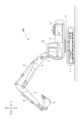
- FIG. 1 is a side view of a shovel according to an embodiment of the present invention
- FIG. 2 is a diagram showing a configuration example of a hydraulic system mounted on the excavator of FIG. 1
- FIG. 4 is a graph illustrating an example of contents of a reference table
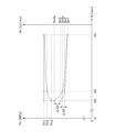
- FIG. 5 is a diagram showing an example of characteristics of a throttle provided in a center bypass oil passage
- FIG. 3 is a diagram showing an example of the relationship between engine speed, control pressure, and displacement.
- FIG. 1 is a side view of a shovel 100.
- FIG. An upper revolving body 3 is rotatably mounted on a lower traveling body 1 of the excavator 100 shown in FIG. 1 through a revolving mechanism 2 .
- a boom 4 is attached to the upper swing body 3 as a working element.
- An arm 5 as a working element is attached to the tip of the boom 4
- a bucket 6 as a working element and an end attachment is attached to the tip of the arm 5 .
- the boom 4, arm 5, and bucket 6 constitute an excavation attachment, which is an example of an attachment.
- Boom 4 is driven by boom cylinder 7
- arm 5 is driven by arm cylinder 8
- bucket 6 is driven by bucket cylinder 9 .
- the upper swing body 3 is provided with a cabin 10 and is equipped with a power source such as an engine 11 .
- FIG. 2 is a diagram showing a configuration example of a hydraulic system mounted on the excavator 100.
- FIG. 2 shows the mechanical driveline, hydraulic lines, pilot lines, and electrical control system in double, solid, dashed, and dotted lines, respectively.
- the hydraulic system of the excavator 100 mainly includes an engine 11, a pump regulator 13, a main pump 14, a pilot pump 15, a control valve unit 17, an operation device 26, a discharge pressure sensor 28, an operation pressure sensor 29, a controller 30, a dial 75, and ECO button 76 and the like.
- the hydraulic system circulates hydraulic oil from a main pump 14 driven by an engine 11, which is an example of a prime mover, through a center bypass oil passage 40 or a parallel oil passage 42 to a hydraulic oil tank. It is configured.
- the engine 11, which is an example of a prime mover, is the driving source of the shovel 100.
- the prime mover is an electric motor connected to a fuel cell, battery, or the like, a gasoline engine, a hydrogen engine, a diesel engine, or the like.
- the engine 11 is, for example, a diesel engine that operates to maintain a predetermined number of revolutions.
- An output shaft of the engine 11 is connected to respective input shafts of the main pump 14 and the pilot pump 15 .
- the main pump 14 is configured to supply hydraulic oil to the control valve unit 17 via a hydraulic oil line.
- the main pump 14 is a swash plate type variable displacement hydraulic pump, and includes a left main pump 14L and a right main pump 14R.
- the main pump 14 is an electrically controlled hydraulic pump.
- the pump regulator 13 is configured to be able to control the discharge flow rate of the main pump 14 .
- the pump regulator 13 controls the discharge flow rate of the main pump 14 by adjusting the tilt angle of the swash plate of the main pump 14 according to the control command from the controller 30 .
- the pump regulator 13 includes a left pump regulator 13L and a right pump regulator 13R.
- the pump regulator 13 controls the discharge flow rate of the main pump 14 by controlling the displacement volume of the main pump 14 according to the control command from the controller 30 .
- the displacement volume of the main pump 14 is the amount of hydraulic oil discharged by the main pump 14 when the main pump 14 rotates once.
- the discharge flow rate of the main pump 14 is the flow rate of hydraulic oil discharged by the main pump 14 per minute.
- the left pump regulator 13L controls the discharge flow rate of the left main pump 14L by controlling the displacement volume of the left main pump 14L in accordance with a control command from the controller 30 .
- the right pump regulator 13R controls the discharge flow rate of the right main pump 14R by controlling the displacement of the right main pump 14R in accordance with a control command from the controller 30.
- the pilot pump 15 is configured to be able to supply hydraulic fluid to hydraulic control equipment including the operating device 26 via a pilot line.
- the pilot pump 15 is a fixed displacement hydraulic pump. Pilot pump 15 may be omitted.
- the function previously performed by the pilot pump 15 may be realized by the main pump 14 .
- the main pump 14 has a function of supplying hydraulic oil to the operating device 26 and the like after reducing the pressure of the hydraulic oil by means of a throttle or the like, in addition to the function of supplying the hydraulic oil to the control valve unit 17 . good too.
- the control valve unit 17 is a hydraulic control device that controls the hydraulic system in the excavator 100.
- the control valve unit 17 includes control valves 171-176 functioning as directional control valves.
- Control valve 175 includes control valve 175L and control valve 175R
- control valve 176 includes control valve 176L and control valve 176R.
- the control valve unit 17 is configured to selectively supply hydraulic fluid discharged from the main pump 14 to one or more hydraulic actuators through control valves 171-176.
- the control valves 171 to 176 for example, control the flow rate of hydraulic fluid flowing from the main pump 14 to the hydraulic actuator and the flow rate of hydraulic fluid flowing from the hydraulic actuator to the hydraulic fluid tank.
- the hydraulic actuators include boom cylinder 7, arm cylinder 8, bucket cylinder 9, traveling hydraulic motor 2M (left traveling hydraulic motor 2ML and right traveling hydraulic motor 2MR), and turning hydraulic motor 2A.
- the operating device 26 is a device used by the operator to operate the actuator.
- the actuators include at least one of hydraulic actuators and electric actuators.
- the operation device 26 is configured to supply the hydraulic oil discharged by the pilot pump 15 to the pilot port of the corresponding control valve in the control valve unit 17 via the pilot line.
- the pressure (pilot pressure) of hydraulic fluid supplied to each of the pilot ports is a pressure corresponding to the operation direction and amount of operation of the operating device 26 corresponding to each of the hydraulic actuators.
- the operating device 26 may be of an electromagnetic pilot type instead of the hydraulic pilot type as described above.
- the control valves in the control valve unit 17 may be electromagnetic solenoid spool valves.
- the discharge pressure sensor 28 is configured to detect the discharge pressure of the main pump 14 .
- the discharge pressure sensor 28 outputs the detected value to the controller 30 .
- the discharge pressure sensor 28 includes a left discharge pressure sensor 28L and a right discharge pressure sensor 28R.
- the left discharge pressure sensor 28L detects the discharge pressure of the left main pump 14L and outputs the detected value to the controller 30 .
- the operation pressure sensor 29 is configured to detect the content of the operation of the operation device 26 by the operator.
- the operation pressure sensor 29 detects the operation direction and the operation amount of the operation device 26 corresponding to each actuator in the form of pressure (operation pressure), and outputs the detected value to the controller 30 .
- the content of the operation of the operation device 26 may be detected using a sensor or device other than the operation pressure sensor, such as a potentiometer.
- the left main pump 14L circulates hydraulic oil to the hydraulic oil tank through the left center bypass oil passage 40L or the left parallel oil passage 42L
- the right main pump 14R circulates the hydraulic oil through the right center bypass oil passage 40R or the right parallel oil passage 42R. Circulate the hydraulic oil to the hydraulic oil tank.
- the left center bypass oil passage 40L is a hydraulic oil line passing through the control valves 171, 173, 175L, and 176L arranged inside the control valve unit 17.
- the right center bypass oil passage 40R is a hydraulic oil line passing through control valves 172, 174, 175R, and 176R arranged in the control valve unit 17.
- the control valve 171 controls the flow of hydraulic fluid in order to supply the hydraulic fluid discharged by the left main pump 14L to the left traveling hydraulic motor 2ML and to discharge the hydraulic fluid discharged by the left traveling hydraulic motor 2ML to the hydraulic fluid tank. It is a switching spool valve.
- the control valve 172 supplies the hydraulic fluid discharged by the right main pump 14R to the right traveling hydraulic motor, and the hydraulic fluid discharged by the right traveling hydraulic motor is discharged to the hydraulic fluid tank. valve.
- the control valve 173 supplies the hydraulic oil discharged by the left main pump 14L to the swing hydraulic motor 2A and discharges the hydraulic oil discharged by the swing hydraulic motor 2A to the hydraulic oil tank. valve.
- the control valve 174 is a spool valve that switches the flow of hydraulic oil to supply the hydraulic oil discharged by the right main pump 14R to the bucket cylinder 9 and to discharge the hydraulic oil in the bucket cylinder 9 to the hydraulic oil tank. .
- the control valve 175L is a spool valve that switches the flow of hydraulic oil in order to supply the hydraulic oil discharged by the left main pump 14L to the boom cylinder 7.
- the control valve 175R is a spool valve that switches the flow of hydraulic oil to supply the hydraulic oil discharged from the right main pump 14R to the boom cylinder 7 and to discharge the hydraulic oil in the boom cylinder 7 to the hydraulic oil tank. .
- the control valve 176L is a spool valve that switches the flow of hydraulic fluid to supply the hydraulic fluid discharged by the left main pump 14L to the arm cylinder 8 and to discharge the hydraulic fluid in the arm cylinder 8 to the hydraulic fluid tank.
- the control valve 176R is a spool valve that switches the flow of hydraulic fluid to supply the hydraulic fluid discharged from the right main pump 14R to the arm cylinder 8 and to discharge the hydraulic fluid in the arm cylinder 8 to the hydraulic fluid tank. .
- the left parallel oil passage 42L is a hydraulic oil line parallel to the left center bypass oil passage 40L.
- the left parallel oil passage 42L can supply hydraulic oil to more downstream control valves when the flow of hydraulic oil passing through the left center bypass oil passage 40L is restricted or blocked by any of the control valves 171, 173, 175L.
- the right parallel oil passage 42R is a hydraulic oil line parallel to the right center bypass oil passage 40R.
- the right parallel oil passage 42R can supply hydraulic oil to control valves further downstream when the flow of hydraulic oil through the right center bypass oil passage 40R is restricted or blocked by any of the control valves 172, 174, 175R. .
- the left pump regulator 13L controls the discharge flow rate of the left main pump 14L by adjusting the swash plate tilt angle of the left main pump 14L according to the discharge pressure of the left main pump 14L. Specifically, for example, the left pump regulator 13L adjusts the swash plate tilt angle of the left main pump 14L according to an increase in the discharge pressure of the left main pump 14L to reduce the discharge flow rate. The same applies to the right pump regulator 13R. This is to prevent the absorption power (for example, absorption horsepower) of the main pump 14 represented by the product of the discharge pressure and the discharge flow rate from exceeding the output power (for example, output horsepower) of the engine 11 .
- absorption power for example, absorption horsepower
- the operating device 26 includes a left operating lever 26L, a right operating lever 26R, and a travel lever 26D as operating levers.
- the travel lever 26D includes a left travel lever 26DL and a right travel lever 26DR.
- the left operating lever 26L is used for turning operation and operating the arm 5.
- the hydraulic oil discharged by the pilot pump 15 is used to apply pressure (pilot pressure) to the pilot port of the control valve 176 in accordance with the lever operation amount.
- the hydraulic oil discharged by the pilot pump 15 is used to apply pressure (pilot pressure) to the pilot port of the control valve 173 in accordance with the amount of lever operation.
- the left operating lever 26L when the left operating lever 26L is operated in the arm closing direction, it causes hydraulic fluid to flow into the right pilot port of the control valve 176L and hydraulic fluid to flow into the left pilot port of the control valve 176R. . Further, when the left operation lever 26L is operated in the arm opening direction, it causes hydraulic fluid to flow into the left pilot port of the control valve 176L and to the right pilot port of the control valve 176R. Further, when the left operation lever 26L is operated in the left turning direction, hydraulic oil flows into the left pilot port of the control valve 173, and when it is operated in the right turning direction, the right pilot port of the control valve 173 Let hydraulic oil flow into
- the right operating lever 26R is used to operate the boom 4 and the bucket 6.
- the hydraulic oil discharged by the pilot pump 15 is used to apply pressure (pilot pressure) to the pilot port of the control valve 175 in accordance with the amount of lever operation.
- the hydraulic oil discharged by the pilot pump 15 is used to apply pressure (pilot pressure) to the pilot port of the control valve 174 in accordance with the amount of lever operation.
- the travel lever 26D is used to operate the crawler 1C.
- the left travel lever 26DL is used to operate the left crawler 1CL.
- the left travel lever 26DL may be configured to interlock with a left travel pedal (not shown).
- the hydraulic oil discharged by the pilot pump 15 is used to apply pressure (pilot pressure) to the pilot port of the control valve 171 in accordance with the amount of lever operation.
- the right travel lever 26DR is used to operate the right crawler.
- the right travel lever 26DR may be configured to interlock with a right travel pedal (not shown).
- the hydraulic oil discharged by the pilot pump 15 is used to apply pressure (pilot pressure) to the pilot port of the control valve 172 in accordance with the amount of lever operation.
- the operation pressure sensors 29 include operation pressure sensors 29LA, 29LB, 29RA, 29RB, 29DL, and 29DR.
- the operation pressure sensor 29LA detects the content of the operator's operation of the left operation lever 26L in the front-rear direction in the form of pressure, and outputs the detected value to the controller 30.
- FIG. The details of the operation include, for example, the lever operation direction and lever operation amount (lever operation angle).
- the operation pressure sensor 29LB detects, in the form of pressure, the content of the operator's operation of the left operation lever 26L in the horizontal direction, and outputs the detected value to the controller 30.
- the operation pressure sensor 29RA detects the content of the operator's operation of the right operation lever 26R in the front-rear direction in the form of pressure, and outputs the detected value to the controller 30.
- the operation pressure sensor 29 RB detects, in the form of pressure, the details of the operator's operation of the right operation lever 26 R in the horizontal direction, and outputs the detected value to the controller 30 .
- the operation pressure sensor 29DL detects, in the form of pressure, the content of the operator's operation of the left traveling lever 26DL in the front-rear direction, and outputs the detected value to the controller 30 .
- the operation pressure sensor 29DR detects, in the form of pressure, the content of the operator's operation of the right travel lever 26DR in the front-rear direction, and outputs the detected value to the controller 30 .
- the controller 30 is an example of a processing circuit and functions as a control device for controlling the shovel 100.
- the controller 30 is configured by a computer including a CPU, a volatile memory device, a non-volatile memory device, and the like.
- the controller 30 receives the output of the operating pressure sensor 29 and outputs a control command to the pump regulator 13 as necessary to change the discharge flow rate of the main pump 14 .
- the controller 30 also receives the output of a control pressure sensor 19 provided upstream of the throttle 18 and outputs a control command to the pump regulator 13 as necessary to change the discharge flow rate of the main pump 14 .
- the throttle 18 includes a left throttle 18L and a right throttle 18R
- the control pressure sensor 19 includes a left control pressure sensor 19L and a right control pressure sensor 19R.
- a left throttle 18L is arranged between the most downstream control valve 176L and the hydraulic oil tank in the left center bypass oil passage 40L. Therefore, the flow of hydraulic oil discharged from the left main pump 14L is restricted by the left throttle 18L.
- the left throttle 18L generates a control pressure (negative control pressure) for controlling the left pump regulator 13L.
- the left control pressure sensor 19L is a sensor for detecting this control pressure, and outputs the detected value to the controller 30.
- the controller 30 controls the discharge flow rate of the left main pump 14L by adjusting the tilt angle of the swash plate of the left main pump 14L according to this control pressure.
- the controller 30 decreases the discharge flow rate of the left main pump 14L as the control pressure increases, and increases the discharge flow rate of the left main pump 14L as the control pressure decreases.
- the discharge flow rate of the right main pump 14R is similarly controlled.
- a right throttle 18R is arranged between the most downstream control valve 176R and the hydraulic oil tank. Therefore, the flow of hydraulic fluid discharged from the right main pump 14R is restricted by the right throttle 18R.
- the right throttle 18R generates a control pressure (negative control pressure) for controlling the right pump regulator 13R.
- the right control pressure sensor 19 ⁇ /b>R is a sensor for detecting this control pressure, and outputs the detected value to the controller 30 .
- the controller 30 controls the discharge flow rate of the right main pump 14R by adjusting the tilt angle of the swash plate of the right main pump 14R according to this control pressure.
- the controller 30 decreases the discharge flow rate of the right main pump 14R as the control pressure increases, and increases the discharge flow rate of the right main pump 14R as the control pressure decreases.
- This control method is also called a “negative control method”.
- the flow of hydraulic oil discharged by the left main pump 14L reduces or eliminates the amount reaching the left throttle 18L, thereby reducing the control pressure (negative control pressure) generated upstream of the left throttle 18L.
- the negative control pressure which is the pressure of the hydraulic fluid in the hydraulic system (control valve unit 17)
- the controller 30 increases the discharge flow rate of the left main pump 14L, circulates a sufficient amount of hydraulic oil to the hydraulic actuator to be operated, and ensures the driving of the hydraulic actuator to be operated.
- the controller 30 similarly controls the discharge flow rate of the right main pump 14R.
- the hydraulic system of FIG. 2 can suppress wasteful energy consumption in the main pump 14 in the standby state. Wasteful energy consumption includes pumping loss caused by the hydraulic oil discharged by the main pump 14 in the center bypass oil passage 40 . Moreover, the hydraulic system of FIG. 2 can reliably supply a sufficient amount of hydraulic oil from the main pump 14 to the hydraulic actuator to be operated when the hydraulic actuator is to be operated.
- the dial 75 is configured so that the target rotation speed of the engine 11 can be adjusted. Specifically, the dial 75 is configured to transmit information indicating the setting state of the target rotation speed of the engine 11 to the controller 30 . In this embodiment, the dial 75 can switch the target rotation speed in 10 steps from the first level (the level corresponding to the highest target rotation speed) to the tenth level (the level corresponding to the lowest target rotation speed). It is configured. The actual number of revolutions of the engine 11 is controlled to the target number of revolutions selected with the dial 75 .
- the ECO button 76 is an example of an operation tool for switching ON/OFF of the ECO mode.
- the ECO mode is one of the work modes of the excavator 100, and is a work mode in which a function for suppressing fuel consumption is executed.
- the work mode of the excavator 100 may include a crane mode or the like that is used during crane work.
- the work mode of the excavator 100 is configured to switch between the ECO mode and the normal mode each time the ECO button 76 is pressed.
- the normal mode is one of the work modes of the excavator 100, and is a work mode in which the function for suppressing fuel consumption is not executed. Functions performed in ECO mode include, for example, the function of slowing attachment movement.
- the expansion and contraction accelerations of the boom cylinder 7, the arm cylinder 8, and the bucket cylinder 9 when moving the operation lever away from the neutral position are limited to a predetermined value or less.
- the maximum expansion/contraction speed is not limited in this embodiment, the maximum expansion/contraction speed may also be limited.
- the expansion/contraction acceleration when returning the operating lever to the neutral position is not limited, but the expansion/contraction acceleration when returning the operating lever to the neutral position may also be limited.
- This function is realized, for example, by limiting the stroke acceleration (increase rate of pilot pressure) of the control valves 174-176.
- the controller 30 has an energy saving control section 30A and a current command output section 30B.
- the energy-saving control unit 30A and the current command output unit 30B are shown separately for convenience of explanation, but they do not have to be physically separated, and may be wholly or partially It may consist of common software or hardware components or a combination thereof.
- the energy saving control section 30A is configured to control the discharge flow rate of the main pump 14. Specifically, the energy saving control section 30A is configured to derive the command value Qn for the discharge flow rate based on the control pressure Pn as the negative control pressure.
- the command value Qn is a value corresponding to the displacement volume.
- the energy saving control section 30A acquires the control pressure Pn output by the control pressure sensor 19 . Then, the energy saving control unit 30A refers to the reference table and derives the command value Qn corresponding to the acquired control pressure Pn.
- the reference table is a reference table that retains the correspondence relationship between the control pressure Pn and the command value Qn in a referable manner, and is stored in advance in the nonvolatile storage device.
- the energy saving control unit 30A may be configured to derive the command value Qn from the control pressure Pn using a calculation formula or the like without using the reference table.
- the current command output unit 30B is configured to output a current command to the pump regulator 13.
- the current command output unit 30B outputs to the pump regulator 13 a current command derived based on the command value Qn output by the energy saving control unit 30A.
- the controller 30 controls the discharge flow rate of the main pump 14.
- the controller 30 separately controls the discharge flow rate of the left main pump 14L and the discharge flow rate of the right main pump 14R.
- the controller 30 derives a current command for the left pump regulator 13L based on the control pressure, which is the pressure of the hydraulic fluid in the left center bypass oil passage 40L detected by the left control pressure sensor 19L.
- the controller 30 controls the discharge flow rate of the left main pump 14L by outputting a current command to the left pump regulator 13L.
- the controller 30 derives a current command for the right pump regulator 13R based on the control pressure, which is the pressure of the working oil in the right center bypass oil passage 40R detected by the right control pressure sensor 19R.
- the controller 30 controls the discharge flow rate of the right main pump 14R by outputting a current command to the right pump regulator 13R.
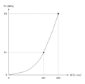
- FIG. 3 is a graph showing an example of the contents of the reference table, showing the correspondence between the control pressure Pn and the command value Qn.
- the control pressure Pn [MPa] detected by the control pressure sensor 19 is plotted on the horizontal axis
- the command value Qn [cc/rev] is plotted on the vertical axis.
- a flow rate control characteristic line GL which is a polygonal line including an inclined line, indicates the relationship between the command value Qn and the control pressure Pn.
- the command value Qn [cc/rev] corresponds to the target displacement volume of the main pump 14 .
- the controller 30 controls the pump regulator 13 by outputting a command value Qn to the pump regulator 13 so that the actual discharge flow rate Q [L/min] of the main pump 14 becomes the target discharge flow rate [L/min]. do.
- the target discharge flow rate [L/min] is, for example, a value calculated by multiplying the rotation speed of the engine 11 and the target displacement volume.
- the contents of the reference table shown in FIG. 3 are used when controlling the discharge flow rate of each of the left main pump 14L and the right main pump 14R.
- the horizontal axis in FIG. 3 corresponds to the control pressure detected by the left control pressure sensor 19L
- the vertical axis in FIG. 3 corresponds to the command value for the discharge flow rate of the left main pump 14L.
- the horizontal axis in FIG. 3 corresponds to the control pressure detected by the right control pressure sensor 19R
- the vertical axis in FIG. corresponds to the value.
- FIG. 3 shows the correspondence relationship between the control pressure Pn and the command value Qn when the engine 11 is rotating at the first rotation speed N1 with a solid first flow rate control characteristic line GL1.
- FIG. 3 shows a second flow control characteristic line GL2 indicated by a dashed line showing the correspondence relationship between the control pressure Pn and the command value Qn when the engine 11 is rotating at a second rotation speed N2 lower than the first rotation speed N1.
- the flow rate control characteristic line is set so as to be adjustable at arbitrary timing, unlike the throttle characteristic shown in FIG.
- the flow rate control characteristic line may be set in advance before being referred to, or may be dynamically set at the time of being referred to.
- FIG. 4 is a diagram showing an example of throttle characteristics, which are the characteristics of the throttle 18 determined by mechanical constraints such as the passage area of the throttle 18.
- FIG. 4 shows an example of the throttle characteristics of the throttle 18 when the engine 11 is rotating at the first speed N1.
- the first rotation speed N1 is, for example, the rated rotation speed.
- the horizontal axis represents the flow rate Qf [L/min] of hydraulic fluid passing through the throttle 18, and the vertical axis represents the control pressure Pn [MPa].
- the diaphragm characteristics of the diaphragm 18 shown in FIG. 4 indicate the diaphragm characteristics of the left diaphragm 18L and the right diaphragm 18R.
- the flow rate Qf of hydraulic oil passing through the throttle 18 corresponds to the discharge amount of the main pump 14 .
- the standby state means a state of the excavator 100 when the engine 11 is in operation and the operation device 26 is not operated.
- the flow rate of hydraulic oil passing through the left throttle 18L corresponds to the discharge rate of the left main pump 14L
- the flow rate of hydraulic oil passing through the right throttle 18R corresponds to the discharge rate of the right main pump 14R. Equivalent to quantity.
- the throttle characteristic shown in FIG. It shows that the control pressure Pn becomes the pressure value P3 at Qf3.
- the energy-saving control unit 30A derives the command value Qn corresponding to the control pressure Pn using the flow rate control characteristic line GL passing through the upper end point A and the lower end point B as shown in FIG. It is configured.
- the upper end point A is a point that defines the upper end of the inclined line included in the flow rate control characteristic line GL, and is represented by the maximum command value Qmax and the pressure value P0.
- the maximum command value Qmax is the upper limit of the command value used in negative control, and is, for example, a set value corresponding to a swash plate tilt angle smaller than the maximum swash plate tilt angle of the main pump 14 by a predetermined angle.
- the maximum command value Qmax and the pressure value P0 are set regardless of the magnitude of the engine speed. However, the maximum command value Qmax and the pressure value P0 may be set differently according to the rotation speed of the engine 11 .
- the lower end point B is a point that defines the lower end of the inclined line included in the flow rate control characteristic line GL, and is represented by the minimum command value Qmin and the pressure value P1.
- the minimum command value Qmin is the lower limit of the command value used in negative control, and is, for example, a set value corresponding to a swash plate tilt angle that is greater than the minimum swash plate tilt angle of the main pump 14 by a predetermined angle.
- a swash-plate tilt angle that is greater than the minimum swash-plate tilt angle by a predetermined angle is, for example, a swash-plate tilt angle corresponding to a standby flow rate.
- the standby flow rate is the flow rate of hydraulic oil passing through the throttle 18 , that is, the flow rate of hydraulic oil discharged by the main pump 14 when the excavator 100 is in the standby state.
- the minimum command value Qmin is set differently depending on the speed of the engine 11, and the pressure value P1 is set regardless of the speed of the engine 11.
- the minimum command value Qmin may be set regardless of the magnitude of the rotation speed of the engine 11 .
- the pressure value P1 may be set differently according to the magnitude of the rotation speed of the engine 11 .
- each of the pressure value P1 and the minimum command value Qmin may be set differently according to the magnitude of the rotation speed of the engine 11 .
- FIG. 3 shows throttle characteristics representing the relationship between the control pressure Pn and the flow rate Qv [cc/rev] of hydraulic oil passing through the throttle 18 when the engine 11 is rotating at the first speed N1 [rpm].
- Line CV first throttle characteristic line CV1 of a dashed-dotted line
- control pressure Pn when engine 11 is rotating at second rotation speed N2 [rpm] and flow rate Qv [cc] of hydraulic oil passing through throttle 18 /rev].
- the flow rate Qv [cc/rev] passing through the throttle 18 corresponds to the displacement of the main pump 14 realized by the command value Qn [cc/rev] in the standby state.
- the value [cc/min] obtained by multiplying the value of the flow rate Qv [cc/rev] corresponding to each point on the first throttle characteristic line CV1 shown in FIG. corresponds to the indicated flow rate Qf [L/min].
- a value [cc /min] corresponds to the value Qf1 of the flow rate Qf [L/min] shown in FIG.
- the rotating shaft of the main pump 14 is connected to the rotating shaft of the engine 11 as a prime mover. Therefore, for example, in the standby state, when the rotation speed of the engine 11, which has been rotating at a predetermined rotation speed, decreases, the main pump 14 discharges the discharge flow rate even if the command value Qn (displacement volume) does not change. (the flow rate of hydraulic oil discharged by the main pump 14 per minute) is decreased.
- the reduction in the rotation speed of the engine 11 is realized by the operator operating the dial 75.
- the operator may adopt a lower rotation speed of the engine 11 than that used for high-load work such as excavation work. be.
- the operator uses the dial 75 to reduce the rotation speed of the engine 11 .
- the control pressure Pn decreases as the discharge flow rate of the main pump 14 decreases.
- the balance point moves on the flow control characteristic line GL, and the standby pressure also drops.
- the balance point is a point on the flow control characteristic line GL when the fluctuations of the command value Qn (displacement volume) and the control pressure Pn converge, and is the intersection of the flow control characteristic line GL and the throttle characteristic line CV. corresponds to Standby pressure means the value of control pressure Pn corresponding to the balance point in the standby state.
- the range RG of the control pressure Pn that can be controlled by the negative control ranges from the range RG1 (the range between the pressure value P0 and the pressure value P1) when the rotation speed of the engine 11 is the first rotation speed N1. It narrows to RG2 (range between pressure value P0 and pressure value Pt). Therefore, the controllability of the discharge flow rate of the main pump 14 deteriorates.
- the controller 30 executes the discharge flow rate control function and changes the flow rate control characteristic of the main pump 14 in accordance with the change in the rotation speed of the engine 11, so that the excavator 100 changes when the rotation speed of the engine 11 is changed. and controllability of the discharge flow rate of the main pump 14 is suppressed or prevented.
- the energy-saving control unit 30A changes the position of the lower end point B in the vertical axis direction, that is, changes the minimum command value Qmin to change the control pressure Pn and the command value Qn. It is configured so that the correspondence can be adjusted.
- the energy saving control unit 30A changes the position of the lower end point B to By making them different, the correspondence relationship between the control pressure Pn and the command value Qn is adjusted to suit the state of the excavator 100 at that time.
- the energy-saving control unit 30A operates when the rotation speed of the engine 11 is the first rotation speed N1 and when the rotation speed of the engine 11 is the second rotation speed N2.
- the position of the lower end point B is changed in two steps, the position of the lower end point B may be changed in three or more steps according to the rotation speed of the engine 11.
- the position of the lower end point B may be changed steplessly according to the number of revolutions of 11.
- the energy saving control unit 30A sets the lower end point B to the lower end point B1 (the minimum command value Qmin is The point at Qmin1) is configured so that the flow control characteristic line GL becomes the first flow control characteristic line GL1.
- the energy saving control unit 30A changes the lower end point B to the lower end point B2 (when the minimum command value Qmin is the value Qmin2), as indicated by the dashed line in FIG. point) so that the flow control characteristic line GL becomes the second flow control characteristic line GL2.
- the energy saving control unit 30A can Even so, the decrease in the control pressure Pn can be suppressed or prevented. Therefore, the energy saving control unit 30A can suppress or prevent a decrease in the standby pressure even when the rotation speed of the engine 11 is decreased while the excavator 100 is in the standby state.
- a state in which the standby pressure is low deteriorates the responsiveness of the movement of the hydraulic actuator when the operation of the operation device 26 is started. Further, when the standby pressure is low, the range RG of the control pressure Pn that can be controlled by negative control is narrowed.
- the energy saving control unit 30A can suppress or prevent such a problem from occurring by suppressing or preventing a decrease in the standby pressure. Therefore, the energy saving control section 30A can improve the operability of the excavator 100 and the controllability of the discharge flow rate of the main pump 14 .
- the hydraulic oil passing through the throttle 18 decreases.
- the rotation speed of the rotation shaft of the main pump 14 connected to the rotation shaft of the engine 11 decreases as the rotation speed of the engine 11 decreases.
- the operator uses the dial 75 to reduce the rotation speed of the engine 11 .
- the control pressure Pn standby pressure
- the command value Qn increases along the flow control characteristic line GL as shown in FIG.
- the command value Qn is the second throttle characteristic line CV2 when the engine speed is the second speed N2 and the second throttle characteristic line CV2. It becomes a value Qmint corresponding to the balance point (lower end point Bt) which is the intersection with the flow rate control characteristic line GL1.
- the standby pressure drops to the pressure value Pt corresponding to the balance point (lower end point Bt).
- the second flow rate control characteristic line GL2 when the second flow rate control characteristic line GL2 is adopted as the flow rate control characteristic line GL corresponding to the second rotation speed N2 by executing the discharge flow rate control function, the second flow rate control characteristic line GL2 and the second flow rate control characteristic line GL2
- the balance point at the intersection with the throttle characteristic line CV2 is the lower end point B2
- the standby pressure (control pressure Pn) is the pressure value P2 corresponding to the balance point (lower end point B2).
- the command value Qn increases from the value Qmin1 to the value Qmin2, and the flow rate of hydraulic oil passing through the throttle 18 increases.
- the pressure value P1 and the pressure value P2 are the same value.
- the energy saving control section 30A can improve the operability of the excavator 100 compared to when the first flow control characteristic line GL1 is adopted as the flow control characteristic line GL. Moreover, the energy saving control section 30A can improve the controllability of the discharge flow rate of the main pump 14 as compared with the case where the first flow rate control characteristic line GL1 is adopted as the flow rate control characteristic line GL. This is because the negative control does not narrow the controllable range RG of the control pressure Pn.
- the controller 30 flexibly adjusts the standby pressure by changing the flow rate control characteristic of the negative control according to the change in the rotation speed of the engine 11, that is, by displacing the lower end point B in the vertical axis direction. You can control it.
- the energy saving control unit 30A adjusts the flow rate control characteristic line GL in accordance with the decrease in the rotation speed of the engine 11, thereby reducing the operability of the excavator 100 due to the decrease in the standby pressure, and Deterioration of the controllability of the discharge flow rate of the main pump 14 can be suppressed or prevented.
- FIG. 5 is a diagram showing an example of the relationship between the rotational speed [rpm] of the engine 11 and the control pressure Pn [MPa] and the command value Qn [cc/rev].
- the solid line in FIG. 5 indicates the relationship between the rotational speed [rpm] of the engine 11 and the control pressure Pn [MPa] when the discharge flow rate control function is executed.
- the dashed line in FIG. 5 indicates that the first flow rate control characteristic represented by the first flow rate control characteristic line GL1 is adopted regardless of the change in the rotation speed [rpm] of the engine 11, that is, when the discharge flow rate control function is not executed.
- 2 shows the relationship between the rotational speed [rpm] of the engine 11 and the control pressure Pn [MPa].
- a dashed line in FIG. 5 indicates the relationship between the rotation speed [rpm] of the engine 11 and the command value Qn [cc/rev] when the discharge flow rate control function is executed.
- the command value Qn [cc/rev] is controlled to increase as the rotation speed [rpm] of the engine 11 decreases, regardless of whether the discharge flow rate control function is being executed. . Also, the command value Qn [cc/rev] when the discharge flow rate control function is executed is controlled to be larger than when the discharge flow rate control function is not executed. Further, as the rotation speed [rpm] of the engine 11 decreases, the command value Qn [cc/rev] changes from the command value Qn [cc/rev] when the discharge flow rate control function is executed. Control is performed so that the difference from the command value Qn [cc/rev] when not executed is increased.
- the command value Qn [cc/rev] when the discharge flow rate control function is not executed is the value Qn1 when the engine 11 is rotating at the first rotation speed N1 [rpm].
- the control pressure Pn [MPa] as the standby pressure is the pressure value Pn1 when the engine 11 is rotating at the first rotation speed N1 [rpm], and the engine 11 is rotating at the second rotation speed N2 [rpm].
- the pressure drops to the pressure value Pn2
- the pressure drops to the pressure value Pn3 when the engine 11 further drops to the third speed N3 [rpm].
- the command value Qn [cc/rev] when the discharge flow rate control function is executed is the same as that when the engine 11 is rotating at the first rotation speed N1 [rpm], and the discharge flow rate control function is not executed. It is the same value as the value Qn1 at the time, increases to the value Qn2a when the engine 11 decreases to the second rotation speed N2 [rpm], and increases to the value Qn3a when the engine 11 further decreases to the third rotation speed N3 [rpm]. .
- the value Qn2a is larger than the value Qn2 by ⁇ Q2
- the value Qn3a is larger than the value Qn3 by ⁇ Q3.
- ⁇ Q3 is larger than ⁇ Q2.
- the controller 30 increases the command value Qn [cc/rev] according to the decrease in the rotation speed of the engine 11 so as to follow the one-dot chain line shown in FIG. 5 by executing the discharge flow rate control function. .
- control pressure Pn [MPa] as the standby pressure decreases from the first rotation speed N1 [rpm] to the second rotation speed N2 [rpm], and further to the third rotation speed N3 [rpm]. Even if it decreases, the pressure value Pn1 is maintained as it is.
- the controller 30 can suppress or prevent the deterioration of the operability of the excavator 100 and the deterioration of the controllability of the discharge flow rate of the main pump 14 due to the decrease in the standby pressure.
- the standby pressure is controlled to be constant at the pressure value Pn1 regardless of the decrease in the rotation speed of the engine 11, but it may be controlled to be within a predetermined range.
- the upper limit of the predetermined range may be the pressure value Pn1, a value larger than the pressure value Pn1, or a value smaller than the pressure value Pn1.
- the lower limit of the predetermined range may be the pressure value Pn1, a value larger than the pressure value Pn1, or a value smaller than the pressure value Pn1.
- the excavator 100 includes, as shown in FIGS. An engine 11 as a prime mover mounted on the revolving structure 3, a main pump 14 as a hydraulic pump driven by the engine 11, and a control device for controlling the discharge flow rate of the main pump 14 according to preset flow control characteristics. and a controller 30 of As shown in FIG. 3, the flow rate control characteristic is a characteristic indicating the correspondence relationship between the displacement of the main pump 14 (command value Qn [cc/reV]) and the negative control pressure (control pressure Pn [MPa]).
- This configuration has the effect of suppressing deterioration of the operability of the excavator 100 even if the operating state of the prime mover changes.
- this configuration can maintain the negative control pressure (control pressure Pn [MPa]) by automatically increasing the displacement volume of the main pump 14 even if the rotation speed of the engine 11 decreases. This brings about the effect of being able to suppress the deterioration of operability.
- this configuration does not limit the range RG of the control pressure Pn that can be controlled by the negative control, so that it is possible to suppress the deterioration of the controllability of the discharge flow rate of the main pump 14 .
- the operating state of the prime mover may be the torque of the engine 11, the exhaust pressure of the engine 11, the rotation speed of the electric motor, the torque of the electric motor, or the power consumption of the electric motor.
- the displacement of the main pump 14 is the negative control pressure (control pressure Pn [MPa] as the standby pressure) when the engine 11 is rotating at the first rotation speed N1 in the standby state. is controlled so that the pressure value P1) and the negative control pressure (pressure value P2 of the control pressure Pn [MPa] as the standby pressure) when the engine 11 is rotating at the second speed N2 are the same.
- the displacement of the main pump 14 is such that the standby pressure when the engine 11 is rotating at the second speed N2 is greater than the standby pressure when the engine 11 is rotating at the first speed N1.
- the standby state is the state of the excavator 100 when the engine 11 is operating and the operating device 26 is not operated.
- This configuration can maintain the standby pressure by automatically increasing the displacement volume of the main pump 14 even if the rotation speed of the engine 11 is reduced in the standby state, so that deterioration of the operability of the excavator 100 can be suppressed. effect. Also, in this configuration, negative control does not narrow the controllable range RG of the control pressure Pn even in the standby state, so that deterioration of the controllability of the discharge flow rate of the main pump 14 in the standby state can be suppressed. bring.
- the displacement volume of the main pump 14 when the engine 11 is rotating at the second rotation speed N2 is larger than the displacement volume of the main pump 14 when the engine 11 is rotating at the first rotation speed N1.
- the controller 30 controls the main pump 14 according to the second flow control characteristic represented by the second flow control characteristic line GL2.
- the controller 30 may be configured to control the discharge flow rate of
- This configuration can maintain the negative control pressure (control pressure Pn [MPa]) by automatically increasing the displacement volume of the main pump 14 even if the rotation speed of the engine 11 drops to the second rotation speed N2. , the effect that deterioration of the operability of the excavator 100 can be suppressed. Further, in this configuration, even if the rotation speed of the engine 11 drops to the second rotation speed N2, the range RG of the control pressure Pn that can be controlled by the negative control is not limited. It brings about the effect of being able to suppress the deterioration of the controllability of
- the inclined line included in the flow rate control characteristic line GL is a straight line connecting the upper end point A and the lower end point B, but two or more straight lines connecting the upper end point A and the lower end point B It may be a polygonal line with an inflection point, a curve connecting the upper end point A and the lower end point B, or a combination of a straight line and a curve connecting the upper end point A and the lower end point B.
- the energy-saving control section 30A is configured to determine the slope included in the flow rate control characteristic line GL by determining the position of the upper end point A and the position of the lower end point B. may be configured to define a sloping line included in the flow control characteristic line GL by determining one or more other points, the slope of the sloping line included in the flow control characteristic line GL By determining the angle, the flow rate control characteristic line GL may be determined (specified).
- the energy saving control section 30A is configured to change the position of the lower end point B based on the information on the rotation speed of the engine 11 output by the dial 75.
- the energy saving control section 30A may be configured to change the position of the lower end point B based on the rotation speed of the engine 11 detected by a rotation speed sensor (not shown).
- the controller 30 is configured to execute the discharge flow rate control function when the rotation speed of the engine 11 changes according to the operator's selection using the dial 75 .
- the controller 30 may be configured to perform the discharge flow rate control function when the rotation speed of the engine 11 changes regardless of selection by the operator.
- the controller 30 may be configured not to execute the discharge flow rate control function when the work mode of the excavator 100 is switched to the power save mode and the rotation speed of the engine 11 is automatically reduced.
- the power save mode is a mode in which fuel consumption by the excavator 100 is suppressed.
- the controller 30 switches the work mode of the shovel 100 to the power save mode when detecting that the operating device 26 has not been operated for a predetermined period of time (for example, 30 seconds).
- the displacement of the main pump 14 is set to a prestored value (typically the minimum value among settable values).
- the controller 30 may be configured not to execute the discharge flow rate control function when the work mode of the excavator 100 is switched to the ECO mode.
- the controller 30 is configured to separately control the discharge flow rate of the left main pump 14L and the discharge flow rate of the right main pump 14R using the contents of the same reference table.
- the controller 30 may be configured to separately control the discharge flow rate of the left main pump 14L and the discharge flow rate of the right main pump 14R using the contents of different lookup tables.
- the controller 30 may be configured to select the lower end point B separately for each of the multiple main pumps 14 .
- the controller 30 rotates at the control pressure Pn (standby pressure) and the second rotation speed N2 when the engine 11 rotates at the first rotation speed N1, as shown in FIG.
- the command value Qn is controlled so that the control pressure Pn (standby pressure) when the engine is on becomes the same pressure value Pn1.
- the controller 30 determines that the standby pressure during rotation at the second rotation speed N2 (standby pressure at low rotation speed) is equal to the standby pressure at rotation at the first rotation speed N1 (high rotation speed).
- the command value Qn may be controlled so as to be higher than the standby pressure of the pressure.
- the controller 30 increases the command value Qn to increase the standby pressure, thereby improving the responsiveness of the hydraulic actuator to start moving.
Abstract
A shovel (100) comprises an engine (11) as a prime mover installed in an upper turning body (3), a main pump (14) as a hydraulic pump that is driven by the engine (11), and a controller (30) as a control device that controls the discharge flow rate of the main pump (14) in accordance with preset flow rate control characteristics. The flow rate control characteristics are characteristics indicating a correspondence relationship between the displacement (command value Qn) of the main pump (14) and negative control pressure (control pressure Pn), and include a first flow rate control characteristic represented by a first flow rate control characteristic line (GL1) that is employed when the engine (11) is rotating at a first rotation speed (N1), and a second flow rate control characteristic represented by a second flow rate control characteristic line (GL2) that is employed when the engine (11) is rotating at a second rotation speed (N2) lower than the first rotation speed (N1).
Description
本開示は、ショベルに関する。
This disclosure relates to excavators.
従来、ネガティブコントロール方式の油圧システムを搭載するショベルが知られている(特許文献1参照。)。ネガティブコントロール方式の油圧システムでは、油圧ポンプが吐出する作動油のうち、ショベルの各部を動かすための油圧アクチュエータに流入しない作動油は、センターバイパス油路に配置された絞りを通って作動油タンクに排出される。油圧ポンプの押しのけ容積は、この絞りの上流側における作動油の圧力である制御圧に応じて制御される。この制御圧は、ネガティブコントロール圧とも称され、絞りを通過する作動油の流量が大きいほど大きくなる。なお、油圧ポンプの押しのけ容積は、油圧ポンプが一回転する際に油圧ポンプが吐出する作動油の量である。油圧アクチュエータが操作されると、油圧アクチュエータに流入する作動油の流量が増加するため、絞りを通過する作動油の流量は減少し、制御圧は低下する。そのため、油圧ポンプは、制御圧が低下するほど押しのけ容積が増加するように制御される。油圧アクチュエータが操作されているときに、十分な量の作動油を油圧アクチュエータに流入させるためである。一方で、油圧ポンプは、制御圧が増加するほど押しのけ容積が減少するように制御される。油圧アクチュエータが操作されていないときに、作動油が無駄に排出されてしまうのを防止するためである。
Conventionally, an excavator equipped with a negative control hydraulic system is known (see Patent Document 1). In a negative control hydraulic system, the hydraulic oil discharged by the hydraulic pump that does not flow into the hydraulic actuators that move the various parts of the excavator flows through the throttle located in the center bypass oil passage to the hydraulic oil tank. Ejected. The displacement of the hydraulic pump is controlled according to the control pressure, which is the pressure of hydraulic fluid upstream of this restriction. This control pressure is also called a negative control pressure, and increases as the flow rate of hydraulic oil passing through the throttle increases. The displacement volume of the hydraulic pump is the amount of hydraulic oil discharged by the hydraulic pump when the hydraulic pump rotates once. When the hydraulic actuator is operated, the flow rate of hydraulic fluid flowing into the hydraulic actuator increases, so the flow rate of hydraulic fluid passing through the throttle decreases and the control pressure drops. Therefore, the hydraulic pump is controlled such that the displacement volume increases as the control pressure decreases. This is to allow a sufficient amount of hydraulic fluid to flow into the hydraulic actuator while the hydraulic actuator is being operated. On the other hand, the hydraulic pump is controlled such that the displacement decreases as the control pressure increases. This is to prevent the hydraulic fluid from being wasted when the hydraulic actuator is not being operated.
しかしながら、特許文献1に開示されるようなネガティブコントロール方式の油圧システムでは、原動機としてのエンジンの回転数が定格回転数等の所定の回転数であるとの前提の下で、油圧ポンプの押しのけ容積と制御圧との対応関係を表す折れ線(流量制御特性線)が固定的に設定されている。そのため、所定の回転数で回転していたエンジンの回転数が変化する等、原動機の動作状態が変化すると、油圧ポンプの吐出流量が低下し、ショベルの操作性が悪化してしまうおそれがある。なお、油圧ポンプの吐出流量は、例えば、一分間当たりに油圧ポンプが吐出する作動油の流量であり、例えば、エンジンの回転数と押しのけ容積との乗算によって算出される。
However, in the negative control type hydraulic system as disclosed in Patent Document 1, under the premise that the rotation speed of the engine as the prime mover is a predetermined rotation speed such as the rated rotation speed, the displacement volume of the hydraulic pump A polygonal line (flow rate control characteristic line) representing the correspondence relationship between the pressure and the control pressure is fixedly set. Therefore, when the operating state of the prime mover changes, such as when the number of revolutions of the engine that has been rotating at a predetermined number of revolutions changes, the discharge flow rate of the hydraulic pump may decrease, and the operability of the excavator may deteriorate. The discharge flow rate of the hydraulic pump is, for example, the flow rate of hydraulic oil discharged by the hydraulic pump per minute, and is calculated, for example, by multiplying the number of revolutions of the engine by the displacement volume.
そこで、原動機の動作状態が変化してもショベルの操作性の悪化を抑制或いは防止できるショベルを提供することが望ましい。
Therefore, it is desirable to provide an excavator that can suppress or prevent deterioration of the operability of the excavator even if the operating state of the prime mover changes.
本発明の実施形態に係るショベルは、下部走行体と、前記下部走行体に旋回可能に搭載された上部旋回体と、前記上部旋回体に搭載された原動機と、前記原動機によって駆動される油圧ポンプと、予め設定された流量制御特性にしたがって前記油圧ポンプの吐出流量を制御する制御装置と、を備え、前記流量制御特性は、前記油圧ポンプの押しのけ容積とネガティブコントロール圧との対応関係を示す特性であり、前記原動機が第1回転数で回転しているときに採用される第1流量制御特性と、前記原動機が前記第1回転数よりも低い第2回転数で回転しているときに採用される第2流量制御特性と、を含む。
An excavator according to an embodiment of the present invention includes a lower traveling body, an upper revolving body rotatably mounted on the lower traveling body, a prime mover mounted on the upper revolving body, and a hydraulic pump driven by the prime mover. and a control device for controlling the discharge flow rate of the hydraulic pump according to a preset flow rate control characteristic, wherein the flow rate control characteristic is a characteristic indicating the correspondence relationship between the displacement volume of the hydraulic pump and the negative control pressure. and a first flow rate control characteristic adopted when the prime mover is rotating at a first speed and a characteristic adopted when the prime mover is rotating at a second speed lower than the first speed. and a second flow control characteristic to be set.
上述のショベルは、原動機の動作状態が変化してもショベルの操作性の悪化を抑制できる。
The excavator described above can suppress the deterioration of the operability of the excavator even if the operating state of the prime mover changes.
最初に、図1を参照して、本発明の実施形態に係る建設機械としての掘削機(ショベル100)について説明する。図1はショベル100の側面図である。図1に示すショベル100の下部走行体1には旋回機構2を介して上部旋回体3が旋回可能に搭載されている。上部旋回体3には作業要素としてのブーム4が取り付けられている。ブーム4の先端には作業要素としてのアーム5が取り付けられ、アーム5の先端に作業要素及びエンドアタッチメントとしてのバケット6が取り付けられている。ブーム4、アーム5、及びバケット6は、アタッチメントの一例である掘削アタッチメントを構成している。ブーム4は、ブームシリンダ7により駆動され、アーム5は、アームシリンダ8により駆動され、バケット6は、バケットシリンダ9により駆動される。上部旋回体3には、キャビン10が設けられ、且つ、エンジン11等の動力源が搭載されている。
First, an excavator (excavator 100) as a construction machine according to an embodiment of the present invention will be described with reference to FIG. FIG. 1 is a side view of a shovel 100. FIG. An upper revolving body 3 is rotatably mounted on a lower traveling body 1 of the excavator 100 shown in FIG. 1 through a revolving mechanism 2 . A boom 4 is attached to the upper swing body 3 as a working element. An arm 5 as a working element is attached to the tip of the boom 4 , and a bucket 6 as a working element and an end attachment is attached to the tip of the arm 5 . The boom 4, arm 5, and bucket 6 constitute an excavation attachment, which is an example of an attachment. Boom 4 is driven by boom cylinder 7 , arm 5 is driven by arm cylinder 8 , and bucket 6 is driven by bucket cylinder 9 . The upper swing body 3 is provided with a cabin 10 and is equipped with a power source such as an engine 11 .
次に、図2を参照し、ショベル100に搭載される油圧システムの構成例について説明する。図2は、ショベル100に搭載される油圧システムの構成例を示す図である。図2は、機械的動力伝達系、作動油ライン、パイロットライン、及び電気制御系を、それぞれ二重線、実線、破線、及び点線で示している。
Next, a configuration example of the hydraulic system mounted on the excavator 100 will be described with reference to FIG. FIG. 2 is a diagram showing a configuration example of a hydraulic system mounted on the excavator 100. As shown in FIG. FIG. 2 shows the mechanical driveline, hydraulic lines, pilot lines, and electrical control system in double, solid, dashed, and dotted lines, respectively.
ショベル100の油圧システムは、主に、エンジン11、ポンプレギュレータ13、メインポンプ14、パイロットポンプ15、コントロールバルブユニット17、操作装置26、吐出圧センサ28、操作圧センサ29、コントローラ30、ダイヤル75、及びECOボタン76等を含む。
The hydraulic system of the excavator 100 mainly includes an engine 11, a pump regulator 13, a main pump 14, a pilot pump 15, a control valve unit 17, an operation device 26, a discharge pressure sensor 28, an operation pressure sensor 29, a controller 30, a dial 75, and ECO button 76 and the like.
図2において、油圧システムは、原動機の一例であるエンジン11によって駆動されるメインポンプ14から、センターバイパス油路40又はパラレル油路42を経て作動油タンクまで作動油を循環させることができるように構成されている。
In FIG. 2, the hydraulic system circulates hydraulic oil from a main pump 14 driven by an engine 11, which is an example of a prime mover, through a center bypass oil passage 40 or a parallel oil passage 42 to a hydraulic oil tank. It is configured.
原動機の一例であるエンジン11は、ショベル100の駆動源である。原動機は、燃料電池若しくはバッテリ等に接続された電動機、ガソリンエンジン、水素エンジン、又はディーゼルエンジン等である。本実施形態では、エンジン11は、例えば、所定の回転数を維持するように動作するディーゼルエンジンである。エンジン11の出力軸は、メインポンプ14及びパイロットポンプ15のそれぞれの入力軸に連結されている。
The engine 11, which is an example of a prime mover, is the driving source of the shovel 100. The prime mover is an electric motor connected to a fuel cell, battery, or the like, a gasoline engine, a hydrogen engine, a diesel engine, or the like. In this embodiment, the engine 11 is, for example, a diesel engine that operates to maintain a predetermined number of revolutions. An output shaft of the engine 11 is connected to respective input shafts of the main pump 14 and the pilot pump 15 .
メインポンプ14は、作動油ラインを介して作動油をコントロールバルブユニット17に供給できるように構成されている。本実施形態では、メインポンプ14は、斜板式可変容量型の油圧ポンプであり、左メインポンプ14L及び右メインポンプ14Rを含む。また、メインポンプ14は、電気制御式の油圧ポンプである。
The main pump 14 is configured to supply hydraulic oil to the control valve unit 17 via a hydraulic oil line. In this embodiment, the main pump 14 is a swash plate type variable displacement hydraulic pump, and includes a left main pump 14L and a right main pump 14R. The main pump 14 is an electrically controlled hydraulic pump.
ポンプレギュレータ13は、メインポンプ14の吐出流量を制御できるように構成されている。本実施形態では、ポンプレギュレータ13は、コントローラ30からの制御指令に応じてメインポンプ14の斜板傾転角を調節することによってメインポンプ14の吐出流量を制御する。また、ポンプレギュレータ13は、左ポンプレギュレータ13L及び右ポンプレギュレータ13Rを含む。
The pump regulator 13 is configured to be able to control the discharge flow rate of the main pump 14 . In this embodiment, the pump regulator 13 controls the discharge flow rate of the main pump 14 by adjusting the tilt angle of the swash plate of the main pump 14 according to the control command from the controller 30 . Also, the pump regulator 13 includes a left pump regulator 13L and a right pump regulator 13R.
具体的には、ポンプレギュレータ13は、コントローラ30からの制御指令に応じてメインポンプ14の押しのけ容積を制御することにより、メインポンプ14の吐出流量を制御する。なお、メインポンプ14の押しのけ容積は、メインポンプ14が一回転する際にメインポンプ14が吐出する作動油の量である。また、メインポンプ14の吐出流量は、一分間当たりにメインポンプ14が吐出する作動油の流量である。より具体的には、左ポンプレギュレータ13Lは、コントローラ30からの制御指令に応じて左メインポンプ14Lの押しのけ容積を制御することにより、左メインポンプ14Lの吐出流量を制御する。同様に、右ポンプレギュレータ13Rは、コントローラ30からの制御指令に応じて右メインポンプ14Rの押しのけ容積を制御することにより、右メインポンプ14Rの吐出流量を制御する。
Specifically, the pump regulator 13 controls the discharge flow rate of the main pump 14 by controlling the displacement volume of the main pump 14 according to the control command from the controller 30 . The displacement volume of the main pump 14 is the amount of hydraulic oil discharged by the main pump 14 when the main pump 14 rotates once. Further, the discharge flow rate of the main pump 14 is the flow rate of hydraulic oil discharged by the main pump 14 per minute. More specifically, the left pump regulator 13L controls the discharge flow rate of the left main pump 14L by controlling the displacement volume of the left main pump 14L in accordance with a control command from the controller 30 . Similarly, the right pump regulator 13R controls the discharge flow rate of the right main pump 14R by controlling the displacement of the right main pump 14R in accordance with a control command from the controller 30. FIG.
パイロットポンプ15は、パイロットラインを介して操作装置26を含む油圧制御機器に作動油を供給できるように構成されている。本実施形態では、パイロットポンプ15は、固定容量型油圧ポンプである。パイロットポンプ15は、省略されてもよい。この場合、パイロットポンプ15が担っていた機能は、メインポンプ14によって実現されてもよい。すなわち、メインポンプ14は、コントロールバルブユニット17に作動油を供給する機能とは別に、絞り等により作動油の圧力を低下させた後で操作装置26等に作動油を供給する機能を備えていてもよい。
The pilot pump 15 is configured to be able to supply hydraulic fluid to hydraulic control equipment including the operating device 26 via a pilot line. In this embodiment, the pilot pump 15 is a fixed displacement hydraulic pump. Pilot pump 15 may be omitted. In this case, the function previously performed by the pilot pump 15 may be realized by the main pump 14 . In other words, the main pump 14 has a function of supplying hydraulic oil to the operating device 26 and the like after reducing the pressure of the hydraulic oil by means of a throttle or the like, in addition to the function of supplying the hydraulic oil to the control valve unit 17 . good too.
コントロールバルブユニット17は、ショベル100における油圧システムを制御する油圧制御装置である。本実施形態では、コントロールバルブユニット17は、方向制御弁として機能する制御弁171~176を含む。制御弁175は制御弁175L及び制御弁175Rを含み、制御弁176は制御弁176L及び制御弁176Rを含む。コントロールバルブユニット17は、制御弁171~176を通じ、メインポンプ14が吐出する作動油を1又は複数の油圧アクチュエータに選択的に供給できるように構成されている。制御弁171~176は、例えば、メインポンプ14から油圧アクチュエータに流れる作動油の流量、及び、油圧アクチュエータから作動油タンクに流れる作動油の流量を制御する。図2に示す例では、油圧アクチュエータは、ブームシリンダ7、アームシリンダ8、バケットシリンダ9、走行油圧モータ2M(左走行油圧モータ2ML及び右走行油圧モータ2MR)、並びに、旋回油圧モータ2Aを含む。
The control valve unit 17 is a hydraulic control device that controls the hydraulic system in the excavator 100. In this embodiment, the control valve unit 17 includes control valves 171-176 functioning as directional control valves. Control valve 175 includes control valve 175L and control valve 175R, and control valve 176 includes control valve 176L and control valve 176R. The control valve unit 17 is configured to selectively supply hydraulic fluid discharged from the main pump 14 to one or more hydraulic actuators through control valves 171-176. The control valves 171 to 176, for example, control the flow rate of hydraulic fluid flowing from the main pump 14 to the hydraulic actuator and the flow rate of hydraulic fluid flowing from the hydraulic actuator to the hydraulic fluid tank. In the example shown in FIG. 2, the hydraulic actuators include boom cylinder 7, arm cylinder 8, bucket cylinder 9, traveling hydraulic motor 2M (left traveling hydraulic motor 2ML and right traveling hydraulic motor 2MR), and turning hydraulic motor 2A.
操作装置26は、操作者がアクチュエータの操作のために用いる装置である。アクチュエータは、油圧アクチュエータ及び電動アクチュエータの少なくとも1つを含む。本実施形態では、操作装置26は、パイロットラインを介して、パイロットポンプ15が吐出する作動油を、コントロールバルブユニット17内の対応する制御弁のパイロットポートに供給できるように構成されている。パイロットポートのそれぞれに供給される作動油の圧力(パイロット圧)は、油圧アクチュエータのそれぞれに対応する操作装置26の操作方向及び操作量に応じた圧力である。但し、操作装置26は、上述のような油圧パイロット式ではなく、電磁パイロット式であってもよい。或いは、コントロールバルブユニット17内の制御弁は、電磁ソレノイド式スプール弁であってもよい。
The operating device 26 is a device used by the operator to operate the actuator. The actuators include at least one of hydraulic actuators and electric actuators. In this embodiment, the operation device 26 is configured to supply the hydraulic oil discharged by the pilot pump 15 to the pilot port of the corresponding control valve in the control valve unit 17 via the pilot line. The pressure (pilot pressure) of hydraulic fluid supplied to each of the pilot ports is a pressure corresponding to the operation direction and amount of operation of the operating device 26 corresponding to each of the hydraulic actuators. However, the operating device 26 may be of an electromagnetic pilot type instead of the hydraulic pilot type as described above. Alternatively, the control valves in the control valve unit 17 may be electromagnetic solenoid spool valves.
吐出圧センサ28は、メインポンプ14の吐出圧を検出できるように構成されている。本実施形態では、吐出圧センサ28は、検出した値をコントローラ30に対して出力する。具体的には、吐出圧センサ28は、左吐出圧センサ28L及び右吐出圧センサ28Rを含む。そして、左吐出圧センサ28Lは、左メインポンプ14Lの吐出圧を検出し、検出した値をコントローラ30に対して出力する。右吐出圧センサ28Rについても同様である。
The discharge pressure sensor 28 is configured to detect the discharge pressure of the main pump 14 . In this embodiment, the discharge pressure sensor 28 outputs the detected value to the controller 30 . Specifically, the discharge pressure sensor 28 includes a left discharge pressure sensor 28L and a right discharge pressure sensor 28R. The left discharge pressure sensor 28L detects the discharge pressure of the left main pump 14L and outputs the detected value to the controller 30 . The same applies to the right discharge pressure sensor 28R.
操作圧センサ29は、操作者による操作装置26の操作の内容を検出できるように構成されている。本実施形態では、操作圧センサ29は、アクチュエータのそれぞれに対応する操作装置26の操作方向及び操作量を圧力(操作圧)の形で検出し、検出した値をコントローラ30に対して出力する。操作装置26の操作の内容は、ポテンショメータ等、操作圧センサ以外の他のセンサ又は装置を用いて検出されてもよい。
The operation pressure sensor 29 is configured to detect the content of the operation of the operation device 26 by the operator. In this embodiment, the operation pressure sensor 29 detects the operation direction and the operation amount of the operation device 26 corresponding to each actuator in the form of pressure (operation pressure), and outputs the detected value to the controller 30 . The content of the operation of the operation device 26 may be detected using a sensor or device other than the operation pressure sensor, such as a potentiometer.
左メインポンプ14Lは、左センターバイパス油路40L又は左パラレル油路42Lを経て作動油タンクまで作動油を循環させ、右メインポンプ14Rは、右センターバイパス油路40R又は右パラレル油路42Rを経て作動油タンクまで作動油を循環させる。
The left main pump 14L circulates hydraulic oil to the hydraulic oil tank through the left center bypass oil passage 40L or the left parallel oil passage 42L, and the right main pump 14R circulates the hydraulic oil through the right center bypass oil passage 40R or the right parallel oil passage 42R. Circulate the hydraulic oil to the hydraulic oil tank.
左センターバイパス油路40Lは、コントロールバルブユニット17内に配置された制御弁171、173、175L、及び176Lを通る作動油ラインである。右センターバイパス油路40Rは、コントロールバルブユニット17内に配置された制御弁172、174、175R、及び176Rを通る作動油ラインである。
The left center bypass oil passage 40L is a hydraulic oil line passing through the control valves 171, 173, 175L, and 176L arranged inside the control valve unit 17. The right center bypass oil passage 40R is a hydraulic oil line passing through control valves 172, 174, 175R, and 176R arranged in the control valve unit 17.
制御弁171は、左メインポンプ14Lが吐出する作動油を左走行油圧モータ2MLへ供給し、且つ、左走行油圧モータ2MLが吐出する作動油を作動油タンクへ排出するために作動油の流れを切り換えるスプール弁である。
The control valve 171 controls the flow of hydraulic fluid in order to supply the hydraulic fluid discharged by the left main pump 14L to the left traveling hydraulic motor 2ML and to discharge the hydraulic fluid discharged by the left traveling hydraulic motor 2ML to the hydraulic fluid tank. It is a switching spool valve.
制御弁172は、右メインポンプ14Rが吐出する作動油を右走行油圧モータへ供給し、且つ、右走行油圧モータが吐出する作動油を作動油タンクへ排出するために作動油の流れを切り換えるスプール弁である。
The control valve 172 supplies the hydraulic fluid discharged by the right main pump 14R to the right traveling hydraulic motor, and the hydraulic fluid discharged by the right traveling hydraulic motor is discharged to the hydraulic fluid tank. valve.
制御弁173は、左メインポンプ14Lが吐出する作動油を旋回油圧モータ2Aへ供給し、且つ、旋回油圧モータ2Aが吐出する作動油を作動油タンクへ排出するために作動油の流れを切り換えるスプール弁である。
The control valve 173 supplies the hydraulic oil discharged by the left main pump 14L to the swing hydraulic motor 2A and discharges the hydraulic oil discharged by the swing hydraulic motor 2A to the hydraulic oil tank. valve.
制御弁174は、右メインポンプ14Rが吐出する作動油をバケットシリンダ9へ供給し、且つ、バケットシリンダ9内の作動油を作動油タンクへ排出するために作動油の流れを切り換えるスプール弁である。
The control valve 174 is a spool valve that switches the flow of hydraulic oil to supply the hydraulic oil discharged by the right main pump 14R to the bucket cylinder 9 and to discharge the hydraulic oil in the bucket cylinder 9 to the hydraulic oil tank. .
制御弁175Lは、左メインポンプ14Lが吐出する作動油をブームシリンダ7へ供給するために作動油の流れを切り換えるスプール弁である。制御弁175Rは、右メインポンプ14Rが吐出する作動油をブームシリンダ7へ供給し、且つ、ブームシリンダ7内の作動油を作動油タンクへ排出するために作動油の流れを切り換えるスプール弁である。
The control valve 175L is a spool valve that switches the flow of hydraulic oil in order to supply the hydraulic oil discharged by the left main pump 14L to the boom cylinder 7. The control valve 175R is a spool valve that switches the flow of hydraulic oil to supply the hydraulic oil discharged from the right main pump 14R to the boom cylinder 7 and to discharge the hydraulic oil in the boom cylinder 7 to the hydraulic oil tank. .
制御弁176Lは、左メインポンプ14Lが吐出する作動油をアームシリンダ8へ供給し、且つ、アームシリンダ8内の作動油を作動油タンクへ排出するために作動油の流れを切り換えるスプール弁である。制御弁176Rは、右メインポンプ14Rが吐出する作動油をアームシリンダ8へ供給し、且つ、アームシリンダ8内の作動油を作動油タンクへ排出するために作動油の流れを切り換えるスプール弁である。
The control valve 176L is a spool valve that switches the flow of hydraulic fluid to supply the hydraulic fluid discharged by the left main pump 14L to the arm cylinder 8 and to discharge the hydraulic fluid in the arm cylinder 8 to the hydraulic fluid tank. . The control valve 176R is a spool valve that switches the flow of hydraulic fluid to supply the hydraulic fluid discharged from the right main pump 14R to the arm cylinder 8 and to discharge the hydraulic fluid in the arm cylinder 8 to the hydraulic fluid tank. .
左パラレル油路42Lは、左センターバイパス油路40Lに並行する作動油ラインである。左パラレル油路42Lは、制御弁171、173、175Lの何れかによって左センターバイパス油路40Lを通る作動油の流れが制限或いは遮断された場合に、より下流の制御弁に作動油を供給できる。右パラレル油路42Rは、右センターバイパス油路40Rに並行する作動油ラインである。右パラレル油路42Rは、制御弁172、174、175Rの何れかによって右センターバイパス油路40Rを通る作動油の流れが制限或いは遮断された場合に、より下流の制御弁に作動油を供給できる。
The left parallel oil passage 42L is a hydraulic oil line parallel to the left center bypass oil passage 40L. The left parallel oil passage 42L can supply hydraulic oil to more downstream control valves when the flow of hydraulic oil passing through the left center bypass oil passage 40L is restricted or blocked by any of the control valves 171, 173, 175L. . The right parallel oil passage 42R is a hydraulic oil line parallel to the right center bypass oil passage 40R. The right parallel oil passage 42R can supply hydraulic oil to control valves further downstream when the flow of hydraulic oil through the right center bypass oil passage 40R is restricted or blocked by any of the control valves 172, 174, 175R. .
左ポンプレギュレータ13Lは、左メインポンプ14Lの吐出圧に応じて左メインポンプ14Lの斜板傾転角を調節することによって、左メインポンプ14Lの吐出流量を制御する。具体的には、左ポンプレギュレータ13Lは、例えば、左メインポンプ14Lの吐出圧の増大に応じて左メインポンプ14Lの斜板傾転角を調節して吐出流量を減少させる。右ポンプレギュレータ13Rについても同様である。吐出圧と吐出流量との積で表されるメインポンプ14の吸収パワー(例えば吸収馬力)がエンジン11の出力パワー(例えば出力馬力)を超えないようにするためである。
The left pump regulator 13L controls the discharge flow rate of the left main pump 14L by adjusting the swash plate tilt angle of the left main pump 14L according to the discharge pressure of the left main pump 14L. Specifically, for example, the left pump regulator 13L adjusts the swash plate tilt angle of the left main pump 14L according to an increase in the discharge pressure of the left main pump 14L to reduce the discharge flow rate. The same applies to the right pump regulator 13R. This is to prevent the absorption power (for example, absorption horsepower) of the main pump 14 represented by the product of the discharge pressure and the discharge flow rate from exceeding the output power (for example, output horsepower) of the engine 11 .
操作装置26は、左操作レバー26L、右操作レバー26R、及び走行レバー26Dを操作レバーとして含む。走行レバー26Dは、左走行レバー26DL及び右走行レバー26DRを含む。
The operating device 26 includes a left operating lever 26L, a right operating lever 26R, and a travel lever 26D as operating levers. The travel lever 26D includes a left travel lever 26DL and a right travel lever 26DR.
左操作レバー26Lは、旋回操作とアーム5の操作に用いられる。左操作レバー26Lは、前後方向に操作されると、パイロットポンプ15が吐出する作動油を利用し、レバー操作量に応じた圧力(パイロット圧)を制御弁176のパイロットポートに作用させる。また、左操作レバー26Lは、左右方向に操作されると、パイロットポンプ15が吐出する作動油を利用し、レバー操作量に応じた圧力(パイロット圧)を制御弁173のパイロットポートに作用させる。
The left operating lever 26L is used for turning operation and operating the arm 5. When the left operation lever 26L is operated in the front-rear direction, the hydraulic oil discharged by the pilot pump 15 is used to apply pressure (pilot pressure) to the pilot port of the control valve 176 in accordance with the lever operation amount. Further, when the left operation lever 26L is operated in the left-right direction, the hydraulic oil discharged by the pilot pump 15 is used to apply pressure (pilot pressure) to the pilot port of the control valve 173 in accordance with the amount of lever operation.
具体的には、左操作レバー26Lは、アーム閉じ方向に操作された場合に、制御弁176Lの右側パイロットポートに作動油を流入させ、且つ、制御弁176Rの左側パイロットポートに作動油を流入させる。また、左操作レバー26Lは、アーム開き方向に操作された場合には、制御弁176Lの左側パイロットポートに作動油を流入させ、且つ、制御弁176Rの右側パイロットポートに作動油を流入させる。また、左操作レバー26Lは、左旋回方向に操作された場合に、制御弁173の左側パイロットポートに作動油を流入させ、右旋回方向に操作された場合に、制御弁173の右側パイロットポートに作動油を流入させる。
Specifically, when the left operating lever 26L is operated in the arm closing direction, it causes hydraulic fluid to flow into the right pilot port of the control valve 176L and hydraulic fluid to flow into the left pilot port of the control valve 176R. . Further, when the left operation lever 26L is operated in the arm opening direction, it causes hydraulic fluid to flow into the left pilot port of the control valve 176L and to the right pilot port of the control valve 176R. Further, when the left operation lever 26L is operated in the left turning direction, hydraulic oil flows into the left pilot port of the control valve 173, and when it is operated in the right turning direction, the right pilot port of the control valve 173 Let hydraulic oil flow into
右操作レバー26Rは、ブーム4の操作とバケット6の操作に用いられる。右操作レバー26Rは、前後方向に操作されると、パイロットポンプ15が吐出する作動油を利用し、レバー操作量に応じた圧力(パイロット圧)を制御弁175のパイロットポートに作用させる。また、右操作レバー26Rは、左右方向に操作されると、パイロットポンプ15が吐出する作動油を利用し、レバー操作量に応じた圧力(パイロット圧)を制御弁174のパイロットポートに作用させる。
The right operating lever 26R is used to operate the boom 4 and the bucket 6. When the right operating lever 26R is operated in the front-rear direction, the hydraulic oil discharged by the pilot pump 15 is used to apply pressure (pilot pressure) to the pilot port of the control valve 175 in accordance with the amount of lever operation. Further, when the right operation lever 26R is operated in the left-right direction, the hydraulic oil discharged by the pilot pump 15 is used to apply pressure (pilot pressure) to the pilot port of the control valve 174 in accordance with the amount of lever operation.
具体的には、右操作レバー26Rは、ブーム下げ方向に操作された場合に、制御弁175Rの左側パイロットポートに作動油を流入させる。また、右操作レバー26Rは、ブーム上げ方向に操作された場合には、制御弁175Lの右側パイロットポートに作動油を流入させ、且つ、制御弁175Rの左側パイロットポートに作動油を流入させる。また、右操作レバー26Rは、バケット閉じ方向に操作された場合に、制御弁174の右側パイロットポートに作動油を流入させ、バケット開き方向に操作された場合に、制御弁174の左側パイロットポートに作動油を流入させる。
Specifically, when the right operation lever 26R is operated in the boom lowering direction, hydraulic fluid flows into the left pilot port of the control valve 175R. Further, when the right operating lever 26R is operated in the boom raising direction, the hydraulic oil flows into the right pilot port of the control valve 175L and the left pilot port of the control valve 175R. When the right operation lever 26R is operated in the bucket closing direction, hydraulic oil flows into the right pilot port of the control valve 174, and when it is operated in the bucket opening direction, the hydraulic oil flows into the left pilot port of the control valve 174. Let hydraulic oil flow.
走行レバー26Dは、クローラ1Cの操作に用いられる。具体的には、左走行レバー26DLは、左クローラ1CLの操作に用いられる。左走行レバー26DLは、不図示の左走行ペダルと連動するように構成されていてもよい。左走行レバー26DLは、前後方向に操作されると、パイロットポンプ15が吐出する作動油を利用し、レバー操作量に応じた圧力(パイロット圧)を制御弁171のパイロットポートに作用させる。右走行レバー26DRは、右クローラの操作に用いられる。右走行レバー26DRは、不図示の右走行ペダルと連動するように構成されていてもよい。右走行レバー26DRは、前後方向に操作されると、パイロットポンプ15が吐出する作動油を利用し、レバー操作量に応じた圧力(パイロット圧)を制御弁172のパイロットポートに作用させる。
The travel lever 26D is used to operate the crawler 1C. Specifically, the left travel lever 26DL is used to operate the left crawler 1CL. The left travel lever 26DL may be configured to interlock with a left travel pedal (not shown). When the left travel lever 26DL is operated in the longitudinal direction, the hydraulic oil discharged by the pilot pump 15 is used to apply pressure (pilot pressure) to the pilot port of the control valve 171 in accordance with the amount of lever operation. The right travel lever 26DR is used to operate the right crawler. The right travel lever 26DR may be configured to interlock with a right travel pedal (not shown). When the right travel lever 26DR is operated in the longitudinal direction, the hydraulic oil discharged by the pilot pump 15 is used to apply pressure (pilot pressure) to the pilot port of the control valve 172 in accordance with the amount of lever operation.
操作圧センサ29は、操作圧センサ29LA、29LB、29RA、29RB、29DL、及び29DRを含む。操作圧センサ29LAは、操作者による左操作レバー26Lに対する前後方向への操作の内容を圧力の形で検出し、検出した値をコントローラ30に対して出力する。操作の内容は、例えば、レバー操作方向及びレバー操作量(レバー操作角度)等である。
The operation pressure sensors 29 include operation pressure sensors 29LA, 29LB, 29RA, 29RB, 29DL, and 29DR. The operation pressure sensor 29LA detects the content of the operator's operation of the left operation lever 26L in the front-rear direction in the form of pressure, and outputs the detected value to the controller 30. FIG. The details of the operation include, for example, the lever operation direction and lever operation amount (lever operation angle).
同様に、操作圧センサ29LBは、操作者による左操作レバー26Lに対する左右方向への操作の内容を圧力の形で検出し、検出した値をコントローラ30に対して出力する。操作圧センサ29RAは、操作者による右操作レバー26Rに対する前後方向への操作の内容を圧力の形で検出し、検出した値をコントローラ30に対して出力する。操作圧センサ29RBは、操作者による右操作レバー26Rに対する左右方向への操作の内容を圧力の形で検出し、検出した値をコントローラ30に対して出力する。操作圧センサ29DLは、操作者による左走行レバー26DLに対する前後方向への操作の内容を圧力の形で検出し、検出した値をコントローラ30に対して出力する。操作圧センサ29DRは、操作者による右走行レバー26DRに対する前後方向への操作の内容を圧力の形で検出し、検出した値をコントローラ30に対して出力する。
Similarly, the operation pressure sensor 29LB detects, in the form of pressure, the content of the operator's operation of the left operation lever 26L in the horizontal direction, and outputs the detected value to the controller 30. The operation pressure sensor 29RA detects the content of the operator's operation of the right operation lever 26R in the front-rear direction in the form of pressure, and outputs the detected value to the controller 30. FIG. The operation pressure sensor 29 RB detects, in the form of pressure, the details of the operator's operation of the right operation lever 26 R in the horizontal direction, and outputs the detected value to the controller 30 . The operation pressure sensor 29DL detects, in the form of pressure, the content of the operator's operation of the left traveling lever 26DL in the front-rear direction, and outputs the detected value to the controller 30 . The operation pressure sensor 29DR detects, in the form of pressure, the content of the operator's operation of the right travel lever 26DR in the front-rear direction, and outputs the detected value to the controller 30 .
コントローラ30は、処理回路の一例であり、ショベル100を制御するための制御装置として機能する。本実施形態では、コントローラ30は、CPU、揮発性記憶装置、及び不揮発性記憶装置等を備えたコンピュータで構成されている。例えば、コントローラ30は、操作圧センサ29の出力を受信し、必要に応じてポンプレギュレータ13に対して制御指令を出力し、メインポンプ14の吐出流量を変化させる。また、コントローラ30は、絞り18の上流に設けられた制御圧センサ19の出力を受信し、必要に応じてポンプレギュレータ13に対して制御指令を出力し、メインポンプ14の吐出流量を変化させる。絞り18は左絞り18L及び右絞り18Rを含み、制御圧センサ19は左制御圧センサ19L及び右制御圧センサ19Rを含む。
The controller 30 is an example of a processing circuit and functions as a control device for controlling the shovel 100. In this embodiment, the controller 30 is configured by a computer including a CPU, a volatile memory device, a non-volatile memory device, and the like. For example, the controller 30 receives the output of the operating pressure sensor 29 and outputs a control command to the pump regulator 13 as necessary to change the discharge flow rate of the main pump 14 . The controller 30 also receives the output of a control pressure sensor 19 provided upstream of the throttle 18 and outputs a control command to the pump regulator 13 as necessary to change the discharge flow rate of the main pump 14 . The throttle 18 includes a left throttle 18L and a right throttle 18R, and the control pressure sensor 19 includes a left control pressure sensor 19L and a right control pressure sensor 19R.
左センターバイパス油路40Lには、最も下流にある制御弁176Lと作動油タンクとの間に左絞り18Lが配置されている。そのため、左メインポンプ14Lが吐出した作動油の流れは、左絞り18Lで制限される。そして、左絞り18Lは、左ポンプレギュレータ13Lを制御するための制御圧(ネガティブコントロール圧)を発生させる。左制御圧センサ19Lは、この制御圧を検出するためのセンサであり、検出した値をコントローラ30に対して出力する。コントローラ30は、この制御圧に応じて左メインポンプ14Lの斜板傾転角を調節することによって、左メインポンプ14Lの吐出流量を制御する。コントローラ30は、この制御圧が大きいほど左メインポンプ14Lの吐出流量を減少させ、この制御圧が小さいほど左メインポンプ14Lの吐出流量を増大させる。右メインポンプ14Rの吐出流量も同様に制御される。具体的には、右センターバイパス油路40Rには、最も下流にある制御弁176Rと作動油タンクとの間に右絞り18Rが配置されている。そのため、右メインポンプ14Rが吐出した作動油の流れは、右絞り18Rで制限される。そして、右絞り18Rは、右ポンプレギュレータ13Rを制御するための制御圧(ネガティブコントロール圧)を発生させる。右制御圧センサ19Rは、この制御圧を検出するためのセンサであり、検出した値をコントローラ30に対して出力する。コントローラ30は、この制御圧に応じて右メインポンプ14Rの斜板傾転角を調節することによって、右メインポンプ14Rの吐出流量を制御する。コントローラ30は、この制御圧が大きいほど右メインポンプ14Rの吐出流量を減少させ、この制御圧が小さいほど右メインポンプ14Rの吐出流量を増大させる。この制御方式は、「ネガティブコントロール方式」とも称される。
A left throttle 18L is arranged between the most downstream control valve 176L and the hydraulic oil tank in the left center bypass oil passage 40L. Therefore, the flow of hydraulic oil discharged from the left main pump 14L is restricted by the left throttle 18L. The left throttle 18L generates a control pressure (negative control pressure) for controlling the left pump regulator 13L. The left control pressure sensor 19L is a sensor for detecting this control pressure, and outputs the detected value to the controller 30. FIG. The controller 30 controls the discharge flow rate of the left main pump 14L by adjusting the tilt angle of the swash plate of the left main pump 14L according to this control pressure. The controller 30 decreases the discharge flow rate of the left main pump 14L as the control pressure increases, and increases the discharge flow rate of the left main pump 14L as the control pressure decreases. The discharge flow rate of the right main pump 14R is similarly controlled. Specifically, in the right center bypass oil passage 40R, a right throttle 18R is arranged between the most downstream control valve 176R and the hydraulic oil tank. Therefore, the flow of hydraulic fluid discharged from the right main pump 14R is restricted by the right throttle 18R. The right throttle 18R generates a control pressure (negative control pressure) for controlling the right pump regulator 13R. The right control pressure sensor 19</b>R is a sensor for detecting this control pressure, and outputs the detected value to the controller 30 . The controller 30 controls the discharge flow rate of the right main pump 14R by adjusting the tilt angle of the swash plate of the right main pump 14R according to this control pressure. The controller 30 decreases the discharge flow rate of the right main pump 14R as the control pressure increases, and increases the discharge flow rate of the right main pump 14R as the control pressure decreases. This control method is also called a “negative control method”.
具体的には、図2で示されるようにショベル100における油圧アクチュエータが何れも操作されていない待機状態の場合、左メインポンプ14Lが吐出する作動油は、左センターバイパス油路40Lを通って左絞り18Lに至る。そして、左メインポンプ14Lが吐出する作動油の流れは、左絞り18Lの上流で発生する制御圧(ネガティブコントロール圧)を増大させる。その結果、コントローラ30は、左メインポンプ14Lの吐出流量を許容最小吐出流量まで減少させ、吐出した作動油が左センターバイパス油路40Lを通過する際の圧力損失(ポンピングロス)を抑制する。一方、何れかの油圧アクチュエータが操作された場合、左メインポンプ14Lが吐出する作動油は、操作対象の油圧アクチュエータに対応する制御弁を介して、操作対象の油圧アクチュエータに流れ込む。そして、左メインポンプ14Lが吐出する作動油の流れは、左絞り18Lに至る量を減少或いは消失させ、左絞り18Lの上流で発生する制御圧(ネガティブコントロール圧)を低下させる。このように、油圧システム(コントロールバルブユニット17)内の作動油の圧力であるネガティブコントロール圧は、操作装置26の操作量が大きいほど小さくなる。その結果、コントローラ30は、左メインポンプ14Lの吐出流量を増大させ、操作対象の油圧アクチュエータに十分な作動油を循環させ、操作対象の油圧アクチュエータの駆動を確かなものとする。なお、コントローラ30は、右メインポンプ14Rの吐出流量も同様に制御する。
Specifically, in the standby state in which none of the hydraulic actuators in the excavator 100 is operated as shown in FIG. It reaches the diaphragm 18L. The flow of hydraulic oil discharged from the left main pump 14L increases the control pressure (negative control pressure) generated upstream of the left throttle 18L. As a result, the controller 30 reduces the discharge flow rate of the left main pump 14L to the allowable minimum discharge flow rate, thereby suppressing pressure loss (pumping loss) when the discharged hydraulic fluid passes through the left center bypass oil passage 40L. On the other hand, when one of the hydraulic actuators is operated, hydraulic fluid discharged from the left main pump 14L flows into the operated hydraulic actuator via the control valve corresponding to the operated hydraulic actuator. Then, the flow of hydraulic oil discharged by the left main pump 14L reduces or eliminates the amount reaching the left throttle 18L, thereby reducing the control pressure (negative control pressure) generated upstream of the left throttle 18L. Thus, the negative control pressure, which is the pressure of the hydraulic fluid in the hydraulic system (control valve unit 17), becomes smaller as the operation amount of the operating device 26 becomes larger. As a result, the controller 30 increases the discharge flow rate of the left main pump 14L, circulates a sufficient amount of hydraulic oil to the hydraulic actuator to be operated, and ensures the driving of the hydraulic actuator to be operated. Note that the controller 30 similarly controls the discharge flow rate of the right main pump 14R.
上述のような構成により、図2の油圧システムは、待機状態においては、メインポンプ14における無駄なエネルギ消費を抑制できる。無駄なエネルギ消費は、メインポンプ14が吐出する作動油がセンターバイパス油路40で発生させるポンピングロスを含む。また、図2の油圧システムは、油圧アクチュエータを作動させる場合には、メインポンプ14から十分な作動油を作動対象の油圧アクチュエータに確実に供給できる。
With the configuration as described above, the hydraulic system of FIG. 2 can suppress wasteful energy consumption in the main pump 14 in the standby state. Wasteful energy consumption includes pumping loss caused by the hydraulic oil discharged by the main pump 14 in the center bypass oil passage 40 . Moreover, the hydraulic system of FIG. 2 can reliably supply a sufficient amount of hydraulic oil from the main pump 14 to the hydraulic actuator to be operated when the hydraulic actuator is to be operated.
ダイヤル75は、エンジン11の目標回転数を調整できるように構成されている。具体的には、ダイヤル75は、エンジン11の目標回転数の設定状態を示す情報をコントローラ30に送信できるように構成されている。本実施形態では、ダイヤル75は、第1レベル(最も高い目標回転数に対応するレベル)から第10レベル(最も低い目標回転数に対応するレベル)の10段階で目標回転数を切り換えできるように構成されている。エンジン11の実際の回転数は、ダイヤル75で選択された目標回転数となるように制御される。
The dial 75 is configured so that the target rotation speed of the engine 11 can be adjusted. Specifically, the dial 75 is configured to transmit information indicating the setting state of the target rotation speed of the engine 11 to the controller 30 . In this embodiment, the dial 75 can switch the target rotation speed in 10 steps from the first level (the level corresponding to the highest target rotation speed) to the tenth level (the level corresponding to the lowest target rotation speed). It is configured. The actual number of revolutions of the engine 11 is controlled to the target number of revolutions selected with the dial 75 .
ECOボタン76は、ECOモードのON・OFFを切り換えるための操作具の一例である。ECOモードは、ショベル100の作業モードの1つであり、燃料の消費を抑制するための機能が実行される作業モードである。ショベル100の作業モードは、クレーン作業の際に利用されるクレーンモード等を含んでいてもよい。本実施形態では、ショベル100の作業モードは、ECOボタン76が押される度に、ECOモードと通常モードとの間で切り換わるように構成されている。通常モードは、ショベル100の作業モードの1つであり、燃料の消費を抑制するための機能が実行されない作業モードである。ECOモードで実行される機能は、例えば、アタッチメントの動きを遅くする機能を含む。アタッチメントの動きを遅くする機能が実行されると、操作レバーを中立位置から遠ざけるときのブームシリンダ7、アームシリンダ8、及びバケットシリンダ9のそれぞれの伸縮加速度が所定値以下に制限される。本実施形態では、最大伸縮速度は制限されないが、最大伸縮速度も制限されるように構成されてもよい。また、本実施形態では、操作レバーを中立位置に戻すときの伸縮加速度は制限されないが、操作レバーを中立位置に戻すときの伸縮加速度も制限されるように構成されてもよい。この機能は、例えば、制御弁174~176のストローク加速度(パイロット圧の増加率)を制限することによって実現される。このECOボタン76を使用することにより、ショベル100の操作者は、必要に応じて、燃料の消費を抑制することができる。そのため、ショベル100は、例えば、操作者がショベル100の作業性を制限してでも燃料の消費を抑制したいと考える場合に対応できる。
The ECO button 76 is an example of an operation tool for switching ON/OFF of the ECO mode. The ECO mode is one of the work modes of the excavator 100, and is a work mode in which a function for suppressing fuel consumption is executed. The work mode of the excavator 100 may include a crane mode or the like that is used during crane work. In this embodiment, the work mode of the excavator 100 is configured to switch between the ECO mode and the normal mode each time the ECO button 76 is pressed. The normal mode is one of the work modes of the excavator 100, and is a work mode in which the function for suppressing fuel consumption is not executed. Functions performed in ECO mode include, for example, the function of slowing attachment movement. When the function of slowing down the movement of the attachment is executed, the expansion and contraction accelerations of the boom cylinder 7, the arm cylinder 8, and the bucket cylinder 9 when moving the operation lever away from the neutral position are limited to a predetermined value or less. Although the maximum expansion/contraction speed is not limited in this embodiment, the maximum expansion/contraction speed may also be limited. Further, in the present embodiment, the expansion/contraction acceleration when returning the operating lever to the neutral position is not limited, but the expansion/contraction acceleration when returning the operating lever to the neutral position may also be limited. This function is realized, for example, by limiting the stroke acceleration (increase rate of pilot pressure) of the control valves 174-176. By using this ECO button 76, the operator of the excavator 100 can suppress fuel consumption as needed. Therefore, the excavator 100 can cope with, for example, the case where the operator wants to suppress fuel consumption even if the workability of the excavator 100 is restricted.
次に、コントローラ30がメインポンプ14の吐出流量を制御する機能(以下、「吐出流量制御機能」とする。)の一例について説明する。本実施形態では、コントローラ30は、省エネルギ制御部30A及び電流指令出力部30Bを有する。図2では、省エネルギ制御部30A及び電流指令出力部30Bは、説明の便宜のために区別されて示されているが、物理的に区別されている必要はなく、全体的に或いは部分的に共通のソフトウェアコンポーネント若しくはハードウェアコンポーネント又はそれらの組み合わせで構成されていてもよい。
Next, an example of the function of the controller 30 to control the discharge flow rate of the main pump 14 (hereinafter referred to as "discharge flow rate control function") will be described. In this embodiment, the controller 30 has an energy saving control section 30A and a current command output section 30B. In FIG. 2, the energy-saving control unit 30A and the current command output unit 30B are shown separately for convenience of explanation, but they do not have to be physically separated, and may be wholly or partially It may consist of common software or hardware components or a combination thereof.
省エネルギ制御部30Aは、メインポンプ14の吐出流量を制御するように構成されている。具体的には、省エネルギ制御部30Aは、ネガティブコントロール圧としての制御圧Pnに基づいて吐出流量の指令値Qnを導き出すように構成されている。指令値Qnは、押しのけ容積に相当する値である。本実施形態では、省エネルギ制御部30Aは、制御圧センサ19が出力する制御圧Pnを取得する。そして、省エネルギ制御部30Aは、参照テーブルを参照し、取得した制御圧Pnに対応する指令値Qnを導き出す。参照テーブルは、制御圧Pnと指令値Qnとの対応関係を参照可能に保持する参照テーブルであり、不揮発性記憶装置に予め記憶されている。但し、省エネルギ制御部30Aは、参照テーブルを用いずに、計算式等を利用して制御圧Pnから指令値Qnを導き出すように構成されていてもよい。
The energy saving control section 30A is configured to control the discharge flow rate of the main pump 14. Specifically, the energy saving control section 30A is configured to derive the command value Qn for the discharge flow rate based on the control pressure Pn as the negative control pressure. The command value Qn is a value corresponding to the displacement volume. In this embodiment, the energy saving control section 30A acquires the control pressure Pn output by the control pressure sensor 19 . Then, the energy saving control unit 30A refers to the reference table and derives the command value Qn corresponding to the acquired control pressure Pn. The reference table is a reference table that retains the correspondence relationship between the control pressure Pn and the command value Qn in a referable manner, and is stored in advance in the nonvolatile storage device. However, the energy saving control unit 30A may be configured to derive the command value Qn from the control pressure Pn using a calculation formula or the like without using the reference table.
電流指令出力部30Bは、ポンプレギュレータ13に対して電流指令を出力するように構成されている。本実施形態では、電流指令出力部30Bは、省エネルギ制御部30Aが出力する指令値Qnに基づいて導き出される電流指令をポンプレギュレータ13に対して出力する。
The current command output unit 30B is configured to output a current command to the pump regulator 13. In this embodiment, the current command output unit 30B outputs to the pump regulator 13 a current command derived based on the command value Qn output by the energy saving control unit 30A.
このようにして、コントローラ30は、メインポンプ14の吐出流量を制御する。図示例では、コントローラ30は、左メインポンプ14Lの吐出流量と右メインポンプ14Rの吐出流量とを別々に制御する。具体的には、コントローラ30は、左制御圧センサ19Lが検出する左センターバイパス油路40Lにおける作動油の圧力である制御圧に基づいて左ポンプレギュレータ13Lに対する電流指令を導き出す。そして、コントローラ30は、左ポンプレギュレータ13Lに対して電流指令を出力することによって左メインポンプ14Lの吐出流量を制御する。また、コントローラ30は、右制御圧センサ19Rが検出する右センターバイパス油路40Rにおける作動油の圧力である制御圧に基づいて右ポンプレギュレータ13Rに対する電流指令を導き出す。そして、コントローラ30は、右ポンプレギュレータ13Rに対して電流指令を出力することによって右メインポンプ14Rの吐出流量を制御する。
In this manner, the controller 30 controls the discharge flow rate of the main pump 14. In the illustrated example, the controller 30 separately controls the discharge flow rate of the left main pump 14L and the discharge flow rate of the right main pump 14R. Specifically, the controller 30 derives a current command for the left pump regulator 13L based on the control pressure, which is the pressure of the hydraulic fluid in the left center bypass oil passage 40L detected by the left control pressure sensor 19L. The controller 30 controls the discharge flow rate of the left main pump 14L by outputting a current command to the left pump regulator 13L. Further, the controller 30 derives a current command for the right pump regulator 13R based on the control pressure, which is the pressure of the working oil in the right center bypass oil passage 40R detected by the right control pressure sensor 19R. The controller 30 controls the discharge flow rate of the right main pump 14R by outputting a current command to the right pump regulator 13R.
次に、図3及び図4を参照し、省エネルギ制御部30Aが参照する参照テーブルの内容の一例について説明する。図3は、参照テーブルの内容の一例を示すグラフであり、制御圧Pnと指令値Qnとの対応関係を示す。具体的には、図3は、制御圧センサ19が検出する制御圧Pn[MPa]を横軸に配し、指令値Qn[cc/rev]を縦軸に配している。傾斜線を含む折れ線である流量制御特性線GLは、指令値Qnと制御圧Pnとの関係を示している。指令値Qn[cc/rev]は、メインポンプ14の目標押しのけ容積に相当する。コントローラ30は、メインポンプ14の実際の吐出流量Q[L/min]が目標吐出流量[L/min]となるようにポンプレギュレータ13に対して指令値Qnを出力することによってポンプレギュレータ13を制御する。目標吐出流量[L/min]は、例えば、エンジン11の回転数と目標押しのけ容積との乗算によって算出される値である。図3に示す参照テーブルの内容は、左メインポンプ14L及び右メインポンプ14Rのそれぞれの吐出流量を制御する際に利用される。左メインポンプ14Lの吐出流量の制御に際しては、図3の横軸は左制御圧センサ19Lが検出する制御圧に対応し、図3の縦軸は左メインポンプ14Lの吐出流量の指令値に対応する。同様に、右メインポンプ14Rの吐出流量の制御に際しては、図3の横軸は右制御圧センサ19Rが検出する制御圧に対応し、図3の縦軸は右メインポンプ14Rの吐出流量の指令値に対応する。
Next, with reference to FIGS. 3 and 4, an example of the contents of the reference table referred to by the energy saving control section 30A will be described. FIG. 3 is a graph showing an example of the contents of the reference table, showing the correspondence between the control pressure Pn and the command value Qn. Specifically, in FIG. 3, the control pressure Pn [MPa] detected by the control pressure sensor 19 is plotted on the horizontal axis, and the command value Qn [cc/rev] is plotted on the vertical axis. A flow rate control characteristic line GL, which is a polygonal line including an inclined line, indicates the relationship between the command value Qn and the control pressure Pn. The command value Qn [cc/rev] corresponds to the target displacement volume of the main pump 14 . The controller 30 controls the pump regulator 13 by outputting a command value Qn to the pump regulator 13 so that the actual discharge flow rate Q [L/min] of the main pump 14 becomes the target discharge flow rate [L/min]. do. The target discharge flow rate [L/min] is, for example, a value calculated by multiplying the rotation speed of the engine 11 and the target displacement volume. The contents of the reference table shown in FIG. 3 are used when controlling the discharge flow rate of each of the left main pump 14L and the right main pump 14R. When controlling the discharge flow rate of the left main pump 14L, the horizontal axis in FIG. 3 corresponds to the control pressure detected by the left control pressure sensor 19L, and the vertical axis in FIG. 3 corresponds to the command value for the discharge flow rate of the left main pump 14L. do. Similarly, when controlling the discharge flow rate of the right main pump 14R, the horizontal axis in FIG. 3 corresponds to the control pressure detected by the right control pressure sensor 19R, and the vertical axis in FIG. corresponds to the value.
より具体的には、図3は、エンジン11が第1回転数N1で回転しているときの制御圧Pnと指令値Qnとの対応関係を実線の第1流量制御特性線GL1で示している。また、図3は、エンジン11が第1回転数N1よりも低い第2回転数N2で回転しているときの制御圧Pnと指令値Qnとの対応関係を破線の第2流量制御特性線GL2で示している。なお、流量制御特性線は、図4に示す絞り特性とは異なり、任意のタイミングで調整できるように設定されている。また、流量制御特性線は、参照される前に予め設定されていてもよく、参照時に動的に設定されてもよい。
More specifically, FIG. 3 shows the correspondence relationship between the control pressure Pn and the command value Qn when the engine 11 is rotating at the first rotation speed N1 with a solid first flow rate control characteristic line GL1. . Further, FIG. 3 shows a second flow control characteristic line GL2 indicated by a dashed line showing the correspondence relationship between the control pressure Pn and the command value Qn when the engine 11 is rotating at a second rotation speed N2 lower than the first rotation speed N1. is shown. The flow rate control characteristic line is set so as to be adjustable at arbitrary timing, unlike the throttle characteristic shown in FIG. Also, the flow rate control characteristic line may be set in advance before being referred to, or may be dynamically set at the time of being referred to.
図4は、絞り18の流路面積等の機械的な制約によって決まる絞り18の特性である絞り特性の一例を示す図である。具体的には、図4は、エンジン11が第1回転数N1で回転しているときの絞り18の絞り特性の一例を示す。第1回転数N1は、例えば、定格回転数である。また、図4は、絞り18を通過する作動油の流量Qf[L/min]を横軸に配し、制御圧Pn[MPa]を縦軸に配している。なお、図4に示す絞り18の絞り特性は、左絞り18L及び右絞り18Rのそれぞれの絞り特性を示している。また、スタンバイ状態では、絞り18を通過する作動油の流量Qfは、メインポンプ14の吐出量に相当する。スタンバイ状態は、エンジン11が稼動中であり、且つ、操作装置26が操作されていないときのショベル100の状態を意味する。具体的には、スタンバイ状態では、左絞り18Lを通過する作動油の流量は、左メインポンプ14Lの吐出量に相当し、右絞り18Rを通過する作動油の流量は、右メインポンプ14Rの吐出量に相当する。
FIG. 4 is a diagram showing an example of throttle characteristics, which are the characteristics of the throttle 18 determined by mechanical constraints such as the passage area of the throttle 18. FIG. Specifically, FIG. 4 shows an example of the throttle characteristics of the throttle 18 when the engine 11 is rotating at the first speed N1. The first rotation speed N1 is, for example, the rated rotation speed. In FIG. 4, the horizontal axis represents the flow rate Qf [L/min] of hydraulic fluid passing through the throttle 18, and the vertical axis represents the control pressure Pn [MPa]. The diaphragm characteristics of the diaphragm 18 shown in FIG. 4 indicate the diaphragm characteristics of the left diaphragm 18L and the right diaphragm 18R. Also, in the standby state, the flow rate Qf of hydraulic oil passing through the throttle 18 corresponds to the discharge amount of the main pump 14 . The standby state means a state of the excavator 100 when the engine 11 is in operation and the operation device 26 is not operated. Specifically, in the standby state, the flow rate of hydraulic oil passing through the left throttle 18L corresponds to the discharge rate of the left main pump 14L, and the flow rate of hydraulic oil passing through the right throttle 18R corresponds to the discharge rate of the right main pump 14R. Equivalent to quantity.
具体的には、図4に示す絞り特性は、絞り18を通過する作動油の流量Qfが値Qf1のときに制御圧Pnが圧力値P1となり、絞り18を通過する作動油の流量Qfが値Qf3のときに制御圧Pnが圧力値P3となることを示している。
Specifically, the throttle characteristic shown in FIG. It shows that the control pressure Pn becomes the pressure value P3 at Qf3.
本実施形態では、省エネルギ制御部30Aは、図3に示すような、上端点A及び下端点Bを通る流量制御特性線GLを利用して制御圧Pnに対応する指令値Qnを導き出すように構成されている。
In this embodiment, the energy-saving control unit 30A derives the command value Qn corresponding to the control pressure Pn using the flow rate control characteristic line GL passing through the upper end point A and the lower end point B as shown in FIG. It is configured.
上端点Aは、流量制御特性線GLに含まれる傾斜線の上端を定める点であり、最大指令値Qmaxと圧力値P0とによって表される。最大指令値Qmaxは、ネガティブコントロールで使用される指令値の上限であり、例えば、メインポンプ14の最大斜板傾転角より所定角度だけ小さい斜板傾転角に対応する設定値である。図3に示す例では、最大指令値Qmax及び圧力値P0は、エンジン11の回転数の大きさとは無関係に設定される。但し、最大指令値Qmax及び圧力値P0は、エンジン11の回転数の大きさに応じて異なるように設定されてもよい。
The upper end point A is a point that defines the upper end of the inclined line included in the flow rate control characteristic line GL, and is represented by the maximum command value Qmax and the pressure value P0. The maximum command value Qmax is the upper limit of the command value used in negative control, and is, for example, a set value corresponding to a swash plate tilt angle smaller than the maximum swash plate tilt angle of the main pump 14 by a predetermined angle. In the example shown in FIG. 3, the maximum command value Qmax and the pressure value P0 are set regardless of the magnitude of the engine speed. However, the maximum command value Qmax and the pressure value P0 may be set differently according to the rotation speed of the engine 11 .
下端点Bは、流量制御特性線GLに含まれる傾斜線の下端を定める点であり、最小指令値Qminと圧力値P1とによって表される。最小指令値Qminは、ネガティブコントロールで使用される指令値の下限であり、例えば、メインポンプ14の最小斜板傾転角より所定角度だけ大きい斜板傾転角に対応する設定値である。最小斜板傾転角より所定角度だけ大きい斜板傾転角は、例えばスタンバイ流量に対応する斜板傾転角である。スタンバイ流量は、ショベル100がスタンバイ状態にあるときに、絞り18を通過する作動油の流量、すなわち、メインポンプ14が吐出する作動油の流量である。図3に示す例では、最小指令値Qminは、エンジン11の回転数の大きさに応じて異なるように設定され、圧力値P1は、エンジン11の回転数の大きさとは無関係に設定される。但し、最小指令値Qminは、エンジン11の回転数の大きさとは無関係に設定されてもよい。この場合、圧力値P1は、エンジン11の回転数の大きさに応じて異なるように設定されてもよい。或いは、圧力値P1及び最小指令値Qminのそれぞれは、エンジン11の回転数の大きさに応じて異なるように設定されてもよい。
The lower end point B is a point that defines the lower end of the inclined line included in the flow rate control characteristic line GL, and is represented by the minimum command value Qmin and the pressure value P1. The minimum command value Qmin is the lower limit of the command value used in negative control, and is, for example, a set value corresponding to a swash plate tilt angle that is greater than the minimum swash plate tilt angle of the main pump 14 by a predetermined angle. A swash-plate tilt angle that is greater than the minimum swash-plate tilt angle by a predetermined angle is, for example, a swash-plate tilt angle corresponding to a standby flow rate. The standby flow rate is the flow rate of hydraulic oil passing through the throttle 18 , that is, the flow rate of hydraulic oil discharged by the main pump 14 when the excavator 100 is in the standby state. In the example shown in FIG. 3, the minimum command value Qmin is set differently depending on the speed of the engine 11, and the pressure value P1 is set regardless of the speed of the engine 11. However, the minimum command value Qmin may be set regardless of the magnitude of the rotation speed of the engine 11 . In this case, the pressure value P1 may be set differently according to the magnitude of the rotation speed of the engine 11 . Alternatively, each of the pressure value P1 and the minimum command value Qmin may be set differently according to the magnitude of the rotation speed of the engine 11 .
また、図3は、エンジン11が第1回転数N1[rpm]で回転しているときの制御圧Pnと絞り18を通過する作動油の流量Qv[cc/rev]との関係を表す絞り特性線CV(一点鎖線の第1絞り特性線CV1)、及び、エンジン11が第2回転数N2[rpm]で回転しているときの制御圧Pnと絞り18を通過する作動油の流量Qv[cc/rev]との関係を表す絞り特性線CV(二点鎖線の第2絞り特性線CV2)を示している。なお、絞り18を通過する流量Qv[cc/rev]は、スタンバイ状態においては、指令値Qn[cc/rev]によって実現されるメインポンプ14の押しのけ容積に対応している。
FIG. 3 shows throttle characteristics representing the relationship between the control pressure Pn and the flow rate Qv [cc/rev] of hydraulic oil passing through the throttle 18 when the engine 11 is rotating at the first speed N1 [rpm]. Line CV (first throttle characteristic line CV1 of a dashed-dotted line), control pressure Pn when engine 11 is rotating at second rotation speed N2 [rpm], and flow rate Qv [cc] of hydraulic oil passing through throttle 18 /rev]. The flow rate Qv [cc/rev] passing through the throttle 18 corresponds to the displacement of the main pump 14 realized by the command value Qn [cc/rev] in the standby state.
また、図3に示す第1絞り特性線CV1上の各点に対応する流量Qv[cc/rev]の値に第1回転数[rpm]を乗じた値[cc/min]は、図4に示す流量Qf[L/min]に対応している。例えば、図3に示す下端点B1における、制御圧Pn[MPa]が圧力値P1のときの最小指令値Qmin[cc/rev]の値Qmin1に第1回転数[rpm]を乗じた値[cc/min]は、図4に示す流量Qf[L/min]の値Qf1に対応している。
Also, the value [cc/min] obtained by multiplying the value of the flow rate Qv [cc/rev] corresponding to each point on the first throttle characteristic line CV1 shown in FIG. corresponds to the indicated flow rate Qf [L/min]. For example, a value [cc /min] corresponds to the value Qf1 of the flow rate Qf [L/min] shown in FIG.
メインポンプ14の回転軸は、原動機としてのエンジン11の回転軸に連結されている。そのため、例えばスタンバイ状態において、所定の回転数で回転していたエンジン11の回転数が低下すると、メインポンプ14は、指令値Qn(押しのけ容積)が変化していない場合であっても、吐出流量(一分間当たりにメインポンプ14が吐出する作動油の流量)を低下させる。図3に示す例では、エンジン11の回転数の低下は、操作者がダイヤル75を操作することによって実現される。操作者は、例えば、均し作業等の負荷の低い作業を行う際に、掘削作業等の負荷の高い作業のときに採用されるエンジン11の回転数に比べて低い回転数を採用する場合がある。この場合、操作者は、ダイヤル75を用いてエンジン11の回転数を低下させる。そして、制御圧Pnは、メインポンプ14の吐出流量の低下に伴って低下する。制御圧Pnが低下すると、バランス点は流量制御特性線GL上を移動し、スタンバイ圧も低下する。なお、バランス点は、指令値Qn(押しのけ容積)及び制御圧Pnのそれぞれの変動が収束したときの流量制御特性線GL上の点であり、流量制御特性線GLと絞り特性線CVとの交点に相当する。スタンバイ圧は、スタンバイ状態でのバランス点に対応する制御圧Pnの値を意味する。
The rotating shaft of the main pump 14 is connected to the rotating shaft of the engine 11 as a prime mover. Therefore, for example, in the standby state, when the rotation speed of the engine 11, which has been rotating at a predetermined rotation speed, decreases, the main pump 14 discharges the discharge flow rate even if the command value Qn (displacement volume) does not change. (the flow rate of hydraulic oil discharged by the main pump 14 per minute) is decreased. In the example shown in FIG. 3, the reduction in the rotation speed of the engine 11 is realized by the operator operating the dial 75. In the example shown in FIG. For example, when performing low-load work such as leveling work, the operator may adopt a lower rotation speed of the engine 11 than that used for high-load work such as excavation work. be. In this case, the operator uses the dial 75 to reduce the rotation speed of the engine 11 . Then, the control pressure Pn decreases as the discharge flow rate of the main pump 14 decreases. When the control pressure Pn drops, the balance point moves on the flow control characteristic line GL, and the standby pressure also drops. The balance point is a point on the flow control characteristic line GL when the fluctuations of the command value Qn (displacement volume) and the control pressure Pn converge, and is the intersection of the flow control characteristic line GL and the throttle characteristic line CV. corresponds to Standby pressure means the value of control pressure Pn corresponding to the balance point in the standby state.
スタンバイ圧が低下すると、操作装置26の操作を開始したときの油圧アクチュエータの動き出しの応答性が悪化し、ショベル100の操作性が悪化してしまう。また、ネガティブコントロールによって制御可能な制御圧Pnの範囲RGは狭くなる。そのため、レバー投入に対する流量制御領域が狭くなり、メインポンプ14の吐出流量の制御性が悪化してしまう。
When the standby pressure drops, the responsiveness of the hydraulic actuator to start moving when the operation of the operation device 26 is started deteriorates, and the operability of the excavator 100 deteriorates. Also, the range RG of the control pressure Pn that can be controlled by negative control is narrowed. As a result, the flow rate control region for lever-on is narrowed, and the controllability of the discharge flow rate of the main pump 14 deteriorates.
図3に示す例では、スタンバイ状態において、第1回転数N1で回転していたエンジン11の回転数が第2回転数N2まで低下すると、メインポンプ14は、指令値Qn(押しのけ容積)が変化していない場合であっても、吐出流量を低下させる。そして、制御圧Pnは、メインポンプ14の吐出流量の低下に伴って低下する。絞り18を通過する作動油の流量が減少するためである。制御圧Pnが低下すると、エンジン11の回転数が第1回転数N1のときに下端点B1の位置にあったバランス点は第1流量制御特性線GL1上を移動しながら下端点Btの位置に収束し、圧力値P1であったスタンバイ圧も圧力値Ptまで低下する。そして、スタンバイ圧が圧力値Ptまで低下すると、操作装置26の操作を開始したときの油圧アクチュエータの動き出しの応答性が悪化し、ショベル100の操作性が悪化してしまう。また、ネガティブコントロールによって制御可能な制御圧Pnの範囲RGは、エンジン11の回転数が第1回転数N1であったときの範囲RG1(圧力値P0と圧力値P1との間の範囲)から範囲RG2(圧力値P0と圧力値Ptとの間の範囲)にまで狭まる。そのため、メインポンプ14の吐出流量の制御性が悪化してしまう。
In the example shown in FIG. 3, when the rotation speed of the engine 11 rotating at the first rotation speed N1 decreases to the second rotation speed N2 in the standby state, the command value Qn (displacement volume) of the main pump 14 changes. Even if not, the discharge flow rate is reduced. Then, the control pressure Pn decreases as the discharge flow rate of the main pump 14 decreases. This is because the flow rate of hydraulic oil passing through the throttle 18 is reduced. When the control pressure Pn decreases, the balance point, which was at the lower end point B1 when the engine speed was the first speed N1, moves along the first flow rate control characteristic line GL1 to the lower end point Bt. It converges, and the standby pressure, which was the pressure value P1, also decreases to the pressure value Pt. When the standby pressure drops to the pressure value Pt, the responsiveness of the hydraulic actuator to start moving when the operation device 26 is started deteriorates, and the operability of the excavator 100 deteriorates. Further, the range RG of the control pressure Pn that can be controlled by the negative control ranges from the range RG1 (the range between the pressure value P0 and the pressure value P1) when the rotation speed of the engine 11 is the first rotation speed N1. It narrows to RG2 (range between pressure value P0 and pressure value Pt). Therefore, the controllability of the discharge flow rate of the main pump 14 deteriorates.
そこで、コントローラ30は、吐出流量制御機能を実行し、エンジン11の回転数の変化に応じてメインポンプ14の流量制御特性を変化させることにより、エンジン11の回転数を変化させたときのショベル100の操作性の悪化、及び、メインポンプ14の吐出流量の制御性の悪化を抑制或いは防止する。
Therefore, the controller 30 executes the discharge flow rate control function and changes the flow rate control characteristic of the main pump 14 in accordance with the change in the rotation speed of the engine 11, so that the excavator 100 changes when the rotation speed of the engine 11 is changed. and controllability of the discharge flow rate of the main pump 14 is suppressed or prevented.
図3に示す例では、省エネルギ制御部30Aは、下端点Bの位置を縦軸方向に変化させることで、すなわち、最小指令値Qminを変化させることで、制御圧Pnと指令値Qnとの対応関係を調整できるように構成されている。
In the example shown in FIG. 3, the energy-saving control unit 30A changes the position of the lower end point B in the vertical axis direction, that is, changes the minimum command value Qmin to change the control pressure Pn and the command value Qn. It is configured so that the correspondence can be adjusted.
具体的には、省エネルギ制御部30Aは、エンジン11の回転数が第1回転数N1のとき、及び、エンジン11の回転数が第2回転数N2ときのそれぞれで、下端点Bの位置を異ならせることによって、制御圧Pnと指令値Qnとの対応関係を、そのときのショベル100の状態に適したものに調整している。なお、図3に示す例では、説明の便宜上、省エネルギ制御部30Aは、エンジン11の回転数が第1回転数N1のとき、及び、エンジン11の回転数が第2回転数N2のときの2段階で下端点Bの位置を変化させているが、エンジン11の回転数の大きさに応じて下端点Bの位置を3段階以上の段階で変化させるように構成されていてもよく、エンジン11の回転数の大きさに応じて下端点Bの位置を無段階に変化させるように構成されていてもよい。
Specifically, the energy saving control unit 30A changes the position of the lower end point B to By making them different, the correspondence relationship between the control pressure Pn and the command value Qn is adjusted to suit the state of the excavator 100 at that time. In the example shown in FIG. 3, for convenience of explanation, the energy-saving control unit 30A operates when the rotation speed of the engine 11 is the first rotation speed N1 and when the rotation speed of the engine 11 is the second rotation speed N2. Although the position of the lower end point B is changed in two steps, the position of the lower end point B may be changed in three or more steps according to the rotation speed of the engine 11. The position of the lower end point B may be changed steplessly according to the number of revolutions of 11.
より具体的には、省エネルギ制御部30Aは、エンジン11の回転数が第1回転数N1のときには、図3の実線で示すように、下端点Bを下端点B1(最小指令値Qminが値Qmin1のときの点)として流量制御特性線GLが第1流量制御特性線GL1となるように構成されている。
More specifically, when the rotational speed of the engine 11 is the first rotational speed N1, the energy saving control unit 30A sets the lower end point B to the lower end point B1 (the minimum command value Qmin is The point at Qmin1) is configured so that the flow control characteristic line GL becomes the first flow control characteristic line GL1.
また、省エネルギ制御部30Aは、エンジン11の回転数が第2回転数N2のときには、図3の破線で示すように、下端点Bを下端点B2(最小指令値Qminが値Qmin2のときの点)として流量制御特性線GLが第2流量制御特性線GL2となるように構成されている。
Further, when the engine speed of the engine 11 is the second speed N2, the energy saving control unit 30A changes the lower end point B to the lower end point B2 (when the minimum command value Qmin is the value Qmin2), as indicated by the dashed line in FIG. point) so that the flow control characteristic line GL becomes the second flow control characteristic line GL2.
このようにエンジン11の回転数の低下に応じて下端点Bの位置を縦軸方向に沿って上方に変位させることにより、省エネルギ制御部30Aは、エンジン11の回転数が低下したときであっても、制御圧Pnの低下を抑制或いは防止できる。そのため、省エネルギ制御部30Aは、ショベル100のスタンバイ状態において、エンジン11の回転数が低下したときであっても、スタンバイ圧の低下を抑制或いは防止できる。
Thus, by displacing the position of the lower end point B upward along the vertical axis direction in accordance with a decrease in the rotation speed of the engine 11, the energy saving control unit 30A can Even so, the decrease in the control pressure Pn can be suppressed or prevented. Therefore, the energy saving control unit 30A can suppress or prevent a decrease in the standby pressure even when the rotation speed of the engine 11 is decreased while the excavator 100 is in the standby state.
スタンバイ圧が低い状態は、操作装置26の操作が開始されたときの油圧アクチュエータの動き出しの応答性を悪化させてしまうため、ショベル100の操作性の悪化を引き起こしてしまう。また、スタンバイ圧が低い状態は、ネガティブコントロールによって制御可能な制御圧Pnの範囲RGを狭めてしまうため、メインポンプ14の吐出流量の制御性の悪化を引き起こしてしまう。
A state in which the standby pressure is low deteriorates the responsiveness of the movement of the hydraulic actuator when the operation of the operation device 26 is started. Further, when the standby pressure is low, the range RG of the control pressure Pn that can be controlled by negative control is narrowed.
省エネルギ制御部30Aは、スタンバイ圧の低下を抑制或いは防止することにより、このような問題が生じてしまうのを抑制或いは防止できる。そのため、省エネルギ制御部30Aは、ショベル100の操作性、及び、メインポンプ14の吐出流量の制御性を高めることができる。
The energy saving control unit 30A can suppress or prevent such a problem from occurring by suppressing or preventing a decrease in the standby pressure. Therefore, the energy saving control section 30A can improve the operability of the excavator 100 and the controllability of the discharge flow rate of the main pump 14 .
例えば、スタンバイ状態において操作者がダイヤル75を用いてエンジン11の回転数を第1回転数N1から第2回転数N2に低下させた場合、絞り18を通過する作動油は減少する。エンジン11の回転軸に連結されたメインポンプ14の回転軸の回転数は、エンジン11の回転数の低下とともに低下するためである。なお、操作者は、例えば、均し作業等の負荷の低い作業を行う際に、掘削作業等の負荷の高い作業のときに採用されるエンジン11の回転数に比べて低い回転数を採用する場合がある。この場合、操作者は、ダイヤル75を用いてエンジン11の回転数を低下させる。
For example, when the operator uses the dial 75 to reduce the rotation speed of the engine 11 from the first rotation speed N1 to the second rotation speed N2 in the standby state, the hydraulic oil passing through the throttle 18 decreases. This is because the rotation speed of the rotation shaft of the main pump 14 connected to the rotation shaft of the engine 11 decreases as the rotation speed of the engine 11 decreases. For example, when performing low-load work such as leveling work, the operator adopts a lower rotational speed of the engine 11 than that used for high-load work such as excavation work. Sometimes. In this case, the operator uses the dial 75 to reduce the rotation speed of the engine 11 .
絞り18を通過する作動油が減少すると、制御圧Pn(スタンバイ圧)も低下するため、指令値Qnは図3に示すように流量制御特性線GLに沿って増加する。仮に流量制御特性線GLが第1流量制御特性線GL1に固定されていた場合には、指令値Qnは、エンジン11の回転数が第2回転数N2のときの第2絞り特性線CV2と第1流量制御特性線GL1との交点であるバランス点(下端点Bt)に対応する値Qmintになる。そして、スタンバイ圧(制御圧Pn)は、バランス点(下端点Bt)に対応する圧力値Ptまで低下する。
When the hydraulic fluid passing through the throttle 18 decreases, the control pressure Pn (standby pressure) also decreases, so the command value Qn increases along the flow control characteristic line GL as shown in FIG. If the flow rate control characteristic line GL is fixed to the first flow rate control characteristic line GL1, the command value Qn is the second throttle characteristic line CV2 when the engine speed is the second speed N2 and the second throttle characteristic line CV2. It becomes a value Qmint corresponding to the balance point (lower end point Bt) which is the intersection with the flow rate control characteristic line GL1. Then, the standby pressure (control pressure Pn) drops to the pressure value Pt corresponding to the balance point (lower end point Bt).
このようにエンジン11の回転数を第1回転数N1から第2回転数N2に低下させた状態では、操作者は、掘削アタッチメントを迅速に動かそうとして操作レバーを迅速に操作した場合であっても、掘削アタッチメントを意図したように迅速に動かすことができない。スタンバイ圧が低下してしまっているためである。旋回油圧モータ2A又は走行油圧モータ2Mを迅速に動かそうとする場合についても同様である。
In this state where the rotation speed of the engine 11 is reduced from the first rotation speed N1 to the second rotation speed N2, even if the operator quickly operates the operation lever to quickly move the excavation attachment, cannot move the drilling attachment as quickly as intended. This is because the standby pressure has decreased. The same applies to the case of quickly moving the turning hydraulic motor 2A or the traveling hydraulic motor 2M.
これに対し、吐出流量制御機能を実行することによって第2回転数N2に対応する流量制御特性線GLとして第2流量制御特性線GL2が採用された場合、第2流量制御特性線GL2と第2絞り特性線CV2との交点であるバランス点は下端点B2となり、スタンバイ圧(制御圧Pn)は、バランス点(下端点B2)に対応する圧力値P2となる。指令値Qnが値Qmin1から値Qmin2に増加し、絞り18を通過する作動油の流量が増加するためである。なお、図3に示す例では、圧力値P1と圧力値P2とは同じ値である。
On the other hand, when the second flow rate control characteristic line GL2 is adopted as the flow rate control characteristic line GL corresponding to the second rotation speed N2 by executing the discharge flow rate control function, the second flow rate control characteristic line GL2 and the second flow rate control characteristic line GL2 The balance point at the intersection with the throttle characteristic line CV2 is the lower end point B2, and the standby pressure (control pressure Pn) is the pressure value P2 corresponding to the balance point (lower end point B2). This is because the command value Qn increases from the value Qmin1 to the value Qmin2, and the flow rate of hydraulic oil passing through the throttle 18 increases. In addition, in the example shown in FIG. 3, the pressure value P1 and the pressure value P2 are the same value.
そのため、エンジン11の回転数が第1回転数N1から第2回転数N2に低減された場合であっても、スタンバイ圧は同じ値で維持される。その結果、省エネルギ制御部30Aは、流量制御特性線GLとして第1流量制御特性線GL1が採用された場合に比べ、ショベル100の操作性を高めることができる。また、省エネルギ制御部30Aは、流量制御特性線GLとして第1流量制御特性線GL1が採用された場合に比べ、メインポンプ14の吐出流量の制御性を高めることができる。ネガティブコントロールによって制御可能な制御圧Pnの範囲RGが狭まることもないためである。
Therefore, even when the rotation speed of the engine 11 is reduced from the first rotation speed N1 to the second rotation speed N2, the standby pressure is maintained at the same value. As a result, the energy saving control section 30A can improve the operability of the excavator 100 compared to when the first flow control characteristic line GL1 is adopted as the flow control characteristic line GL. Moreover, the energy saving control section 30A can improve the controllability of the discharge flow rate of the main pump 14 as compared with the case where the first flow rate control characteristic line GL1 is adopted as the flow rate control characteristic line GL. This is because the negative control does not narrow the controllable range RG of the control pressure Pn.
このように、コントローラ30は、エンジン11の回転数の変化に応じてネガティブコントロールの流量制御特性を変化させることにより、すなわち、下端点Bを縦軸方向に変位させることにより、スタンバイ圧を柔軟に制御できる。具体的には、省エネルギ制御部30Aは、エンジン11の回転数の低下に応じて流量制御特性線GLを調整することにより、スタンバイ圧の低下に起因するショベル100の操作性の悪化、及び、メインポンプ14の吐出流量の制御性の悪化を抑制或いは防止できる。
In this way, the controller 30 flexibly adjusts the standby pressure by changing the flow rate control characteristic of the negative control according to the change in the rotation speed of the engine 11, that is, by displacing the lower end point B in the vertical axis direction. You can control it. Specifically, the energy saving control unit 30A adjusts the flow rate control characteristic line GL in accordance with the decrease in the rotation speed of the engine 11, thereby reducing the operability of the excavator 100 due to the decrease in the standby pressure, and Deterioration of the controllability of the discharge flow rate of the main pump 14 can be suppressed or prevented.
次に、図5を参照し、スタンバイ状態におけるエンジン11の回転数[rpm]と制御圧Pn[MPa]及び指令値Qn[cc/rev]のそれぞれとの関係について説明する。図5は、エンジン11の回転数[rpm]と制御圧Pn[MPa]及び指令値Qn[cc/rev]のそれぞれとの関係の一例を示す図である。
Next, with reference to FIG. 5, the relationship between the number of revolutions [rpm] of the engine 11 in the standby state, the control pressure Pn [MPa], and the command value Qn [cc/rev] will be described. FIG. 5 is a diagram showing an example of the relationship between the rotational speed [rpm] of the engine 11 and the control pressure Pn [MPa] and the command value Qn [cc/rev].
具体的には、図5の実線は、吐出流量制御機能が実行されている場合のエンジン11の回転数[rpm]と制御圧Pn[MPa]との関係を示す。図5の破線は、吐出流量制御機能が実行されていない場合、すなわち、エンジン11の回転数[rpm]の変化にかかわらず第1流量制御特性線GL1で表される第1流量制御特性が採用され続ける場合のエンジン11の回転数[rpm]と制御圧Pn[MPa]との関係を示す。図5の一点鎖線は、吐出流量制御機能が実行されている場合のエンジン11の回転数[rpm]と指令値Qn[cc/rev]との関係を示す。図5の二点鎖線は、吐出流量制御機能が実行されていない場合、すなわち、エンジン11の回転数[rpm]の変化にかかわらず第1流量制御特性線GL1で表される第1流量制御特性が採用され続ける場合のエンジン11の回転数[rpm]と指令値Qn[cc/rev]との関係を示す。
Specifically, the solid line in FIG. 5 indicates the relationship between the rotational speed [rpm] of the engine 11 and the control pressure Pn [MPa] when the discharge flow rate control function is executed. The dashed line in FIG. 5 indicates that the first flow rate control characteristic represented by the first flow rate control characteristic line GL1 is adopted regardless of the change in the rotation speed [rpm] of the engine 11, that is, when the discharge flow rate control function is not executed. 2 shows the relationship between the rotational speed [rpm] of the engine 11 and the control pressure Pn [MPa]. A dashed line in FIG. 5 indicates the relationship between the rotation speed [rpm] of the engine 11 and the command value Qn [cc/rev] when the discharge flow rate control function is executed. The two-dot chain line in FIG. 5 indicates the first flow rate control characteristic represented by the first flow rate control characteristic line GL1 when the discharge flow rate control function is not executed, that is, regardless of the change in the rotation speed [rpm] of the engine 11. is continuously adopted, the relationship between the rotation speed [rpm] of the engine 11 and the command value Qn [cc/rev] is shown.
より具体的には、指令値Qn[cc/rev]は、吐出流量制御機能が実行されているか否かにかかわらず、エンジン11の回転数[rpm]が低下するにつれて増加するように制御される。また、吐出流量制御機能が実行されているときの指令値Qn[cc/rev]は、吐出流量制御機能が実行されていない場合に比べて大きくなるように制御される。また、指令値Qn[cc/rev]は、エンジン11の回転数[rpm]が低下するにつれ、吐出流量制御機能が実行されているときの指令値Qn[cc/rev]と吐出流量制御機能が実行されていないときの指令値Qn[cc/rev]との差が大きくなるように制御される。
More specifically, the command value Qn [cc/rev] is controlled to increase as the rotation speed [rpm] of the engine 11 decreases, regardless of whether the discharge flow rate control function is being executed. . Also, the command value Qn [cc/rev] when the discharge flow rate control function is executed is controlled to be larger than when the discharge flow rate control function is not executed. Further, as the rotation speed [rpm] of the engine 11 decreases, the command value Qn [cc/rev] changes from the command value Qn [cc/rev] when the discharge flow rate control function is executed. Control is performed so that the difference from the command value Qn [cc/rev] when not executed is increased.
図5に示す例では、吐出流量制御機能が実行されていないときの指令値Qn[cc/rev]は、エンジン11が第1回転数N1[rpm]で回転しているときに値Qn1であり、エンジン11が第2回転数N2[rpm]まで低下すると値Qn2まで増加し、エンジン11が更に第3回転数N3[rpm]まで低下すると値Qn3まで増加する。この場合、スタンバイ圧としての制御圧Pn[MPa]は、エンジン11が第1回転数N1[rpm]で回転しているときに圧力値Pn1であり、エンジン11が第2回転数N2[rpm]まで低下すると圧力値Pn2まで低下し、エンジン11が更に第3回転数N3[rpm]まで低下すると圧力値Pn3まで低下する。
In the example shown in FIG. 5, the command value Qn [cc/rev] when the discharge flow rate control function is not executed is the value Qn1 when the engine 11 is rotating at the first rotation speed N1 [rpm]. , increases to a value Qn2 when the engine 11 decreases to the second rotation speed N2 [rpm], and increases to a value Qn3 when the engine 11 further decreases to the third rotation speed N3 [rpm]. In this case, the control pressure Pn [MPa] as the standby pressure is the pressure value Pn1 when the engine 11 is rotating at the first rotation speed N1 [rpm], and the engine 11 is rotating at the second rotation speed N2 [rpm]. When the pressure drops to the pressure value Pn2, the pressure drops to the pressure value Pn3 when the engine 11 further drops to the third speed N3 [rpm].
一方、吐出流量制御機能が実行されているときの指令値Qn[cc/rev]は、エンジン11が第1回転数N1[rpm]で回転しているときには、吐出流量制御機能が実行されていないときの値Qn1と同じ値であり、エンジン11が第2回転数N2[rpm]まで低下すると値Qn2aまで増加し、エンジン11が更に第3回転数N3[rpm]まで低下すると値Qn3aまで増加する。なお、値Qn2aは、値Qn2よりもΔQ2だけ大きい値であり、値Qn3aは、値Qn3よりもΔQ3だけ大きい値である。そして、ΔQ3は、ΔQ2よりも大きい。
On the other hand, the command value Qn [cc/rev] when the discharge flow rate control function is executed is the same as that when the engine 11 is rotating at the first rotation speed N1 [rpm], and the discharge flow rate control function is not executed. It is the same value as the value Qn1 at the time, increases to the value Qn2a when the engine 11 decreases to the second rotation speed N2 [rpm], and increases to the value Qn3a when the engine 11 further decreases to the third rotation speed N3 [rpm]. . The value Qn2a is larger than the value Qn2 by ΔQ2, and the value Qn3a is larger than the value Qn3 by ΔQ3. And ΔQ3 is larger than ΔQ2.
このように、コントローラ30は、吐出流量制御機能を実行することにより、図5に示す一点鎖線を辿るように、エンジン11の回転数の低下に応じて指令値Qn[cc/rev]を増大させる。
Thus, the controller 30 increases the command value Qn [cc/rev] according to the decrease in the rotation speed of the engine 11 so as to follow the one-dot chain line shown in FIG. 5 by executing the discharge flow rate control function. .
この制御により、スタンバイ圧としての制御圧Pn[MPa]は、エンジン11が第1回転数N1[rpm]から第2回転数N2[rpm]まで低下し、更に第3回転数N3[rpm]まで低下しても、圧力値Pn1のままで維持される。
With this control, the control pressure Pn [MPa] as the standby pressure decreases from the first rotation speed N1 [rpm] to the second rotation speed N2 [rpm], and further to the third rotation speed N3 [rpm]. Even if it decreases, the pressure value Pn1 is maintained as it is.
その結果、コントローラ30は、スタンバイ圧の低下に起因するショベル100の操作性の悪化、及び、メインポンプ14の吐出流量の制御性の悪化を抑制或いは防止できる。
As a result, the controller 30 can suppress or prevent the deterioration of the operability of the excavator 100 and the deterioration of the controllability of the discharge flow rate of the main pump 14 due to the decrease in the standby pressure.
なお、図5に示す例では、スタンバイ圧は、エンジン11の回転数の低下にかかわらず圧力値Pn1で一定となるように制御されるが、所定の範囲内に収まるように制御されてもよい。この場合、所定の範囲の上限値は、圧力値Pn1であってもよく、圧力値Pn1よりも大きい値であってもよく、圧力値Pn1よりも小さい値であってもよい。また、所定の範囲の下限値は、圧力値Pn1であってもよく、圧力値Pn1よりも大きい値であってもよく、圧力値Pn1よりも小さい値であってもよい。
In the example shown in FIG. 5, the standby pressure is controlled to be constant at the pressure value Pn1 regardless of the decrease in the rotation speed of the engine 11, but it may be controlled to be within a predetermined range. . In this case, the upper limit of the predetermined range may be the pressure value Pn1, a value larger than the pressure value Pn1, or a value smaller than the pressure value Pn1. Also, the lower limit of the predetermined range may be the pressure value Pn1, a value larger than the pressure value Pn1, or a value smaller than the pressure value Pn1.
上述のように、本発明の実施形態に係るショベル100は、図1及び図2に示すように、下部走行体1と、下部走行体1に旋回可能に搭載された上部旋回体3と、上部旋回体3に搭載された原動機としてのエンジン11と、エンジン11によって駆動される油圧ポンプとしてのメインポンプ14と、予め設定された流量制御特性にしたがってメインポンプ14の吐出流量を制御する制御装置としてのコントローラ30と、を備えている。流量制御特性は、図3に示すように、メインポンプ14の押しのけ容積(指令値Qn[cc/reV])とネガティブコントロール圧(制御圧Pn[MPa])との対応関係を示す特性であり、エンジン11が第1回転数N1で回転しているときに採用される第1流量制御特性線GL1で表される第1流量制御特性と、エンジン11が第1回転数N1よりも低い第2回転数N2で回転しているときに採用される第2流量制御特性線GL2で表される第2流量制御特性と、を含む。
As described above, the excavator 100 according to the embodiment of the present invention includes, as shown in FIGS. An engine 11 as a prime mover mounted on the revolving structure 3, a main pump 14 as a hydraulic pump driven by the engine 11, and a control device for controlling the discharge flow rate of the main pump 14 according to preset flow control characteristics. and a controller 30 of As shown in FIG. 3, the flow rate control characteristic is a characteristic indicating the correspondence relationship between the displacement of the main pump 14 (command value Qn [cc/reV]) and the negative control pressure (control pressure Pn [MPa]). A first flow rate control characteristic represented by a first flow rate control characteristic line GL1 adopted when the engine 11 is rotating at the first rotation speed N1, and a second rotation at which the engine 11 is lower than the first rotation speed N1 and a second flow control characteristic represented by a second flow control characteristic line GL2 adopted when rotating at number N2.
この構成は、原動機の動作状態が変化してもショベル100の操作性の悪化を抑制できるという効果をもたらす。例えば、この構成は、エンジン11の回転数が低下したとしても、メインポンプ14の押しのけ容積を自動的に増加させることによってネガティブコントロール圧(制御圧Pn[MPa])を維持できるため、ショベル100の操作性の悪化を抑制できるという効果をもたらす。また、この構成は、ネガティブコントロールによって制御可能な制御圧Pnの範囲RGが制限されることもないため、メインポンプ14の吐出流量の制御性の悪化を抑制できるという効果をもたらす。なお、原動機の動作状態は、エンジン11のトルク、エンジン11の排気圧、電動機の回転速度、電動機のトルク、又は電動機の消費電力等の状態であってもよい。
This configuration has the effect of suppressing deterioration of the operability of the excavator 100 even if the operating state of the prime mover changes. For example, this configuration can maintain the negative control pressure (control pressure Pn [MPa]) by automatically increasing the displacement volume of the main pump 14 even if the rotation speed of the engine 11 decreases. This brings about the effect of being able to suppress the deterioration of operability. Moreover, this configuration does not limit the range RG of the control pressure Pn that can be controlled by the negative control, so that it is possible to suppress the deterioration of the controllability of the discharge flow rate of the main pump 14 . The operating state of the prime mover may be the torque of the engine 11, the exhaust pressure of the engine 11, the rotation speed of the electric motor, the torque of the electric motor, or the power consumption of the electric motor.
また、メインポンプ14の押しのけ容積は、図3に示すように、スタンバイ状態において、エンジン11が第1回転数N1で回転しているときのネガティブコントロール圧(スタンバイ圧としての制御圧Pn[MPa]の圧力値P1)とエンジン11が前記第2回転数N2で回転しているときのネガティブコントロール圧(スタンバイ圧としての制御圧Pn[MPa]の圧力値P2)とが同じになるように制御されてもよい。或いは、メインポンプ14の押しのけ容積は、エンジン11が前記第2回転数N2で回転しているときのスタンバイ圧が、エンジン11が第1回転数N1で回転しているときのスタンバイ圧より大きくなるように制御されてもよい。なお、スタンバイ状態は、エンジン11が稼動しているときであり、且つ、操作装置26が操作されていないときのショベル100の状態である。
Further, as shown in FIG. 3, the displacement of the main pump 14 is the negative control pressure (control pressure Pn [MPa] as the standby pressure) when the engine 11 is rotating at the first rotation speed N1 in the standby state. is controlled so that the pressure value P1) and the negative control pressure (pressure value P2 of the control pressure Pn [MPa] as the standby pressure) when the engine 11 is rotating at the second speed N2 are the same. may Alternatively, the displacement of the main pump 14 is such that the standby pressure when the engine 11 is rotating at the second speed N2 is greater than the standby pressure when the engine 11 is rotating at the first speed N1. may be controlled as follows. The standby state is the state of the excavator 100 when the engine 11 is operating and the operating device 26 is not operated.
この構成は、スタンバイ状態において、エンジン11の回転数が低下したとしても、メインポンプ14の押しのけ容積を自動的に増加させることによってスタンバイ圧を維持できるため、ショベル100の操作性の悪化を抑制できるという効果をもたらす。また、この構成は、スタンバイ状態においても、ネガティブコントロールによって制御可能な制御圧Pnの範囲RGが狭められることがないため、スタンバイ状態におけるメインポンプ14の吐出流量の制御性の悪化を抑制できるという効果をもたらす。
This configuration can maintain the standby pressure by automatically increasing the displacement volume of the main pump 14 even if the rotation speed of the engine 11 is reduced in the standby state, so that deterioration of the operability of the excavator 100 can be suppressed. effect. Also, in this configuration, negative control does not narrow the controllable range RG of the control pressure Pn even in the standby state, so that deterioration of the controllability of the discharge flow rate of the main pump 14 in the standby state can be suppressed. bring.
また、エンジン11が第2回転数N2で回転しているときのメインポンプ14の押しのけ容積は、エンジン11が第1回転数N1で回転しているときのメインポンプ14の押しのけ容積よりも大きくなるように制御されてもよい。図3に示す例では、制御圧Pn[MPa]が圧力値P1となる状態において、エンジン11が第1回転数N1で回転しているときのメインポンプ14の押しのけ容積は値Qmin1となるように制御され、エンジン11が第2回転数N2で回転しているときのメインポンプ14の押しのけ容積は値Qmin1よりも大きい値Qmin2となるように制御される。
Further, the displacement volume of the main pump 14 when the engine 11 is rotating at the second rotation speed N2 is larger than the displacement volume of the main pump 14 when the engine 11 is rotating at the first rotation speed N1. may be controlled as follows. In the example shown in FIG. 3, when the control pressure Pn [MPa] is the pressure value P1, the displacement of the main pump 14 when the engine 11 is rotating at the first rotation speed N1 is set to the value Qmin1. Thus, the displacement of the main pump 14 when the engine 11 is rotating at the second speed N2 is controlled to a value Qmin2 larger than the value Qmin1.
また、コントローラ30は、図3に示すように、エンジン11の回転数が第2回転数N2まで低下した場合、第2流量制御特性線GL2で表される第2流量制御特性にしたがってメインポンプ14の吐出流量を制御するように構成されていてもよい。
Further, as shown in FIG. 3, when the rotation speed of the engine 11 decreases to the second rotation speed N2, the controller 30 controls the main pump 14 according to the second flow control characteristic represented by the second flow control characteristic line GL2. may be configured to control the discharge flow rate of
この構成は、エンジン11の回転数が第2回転数N2まで低下したとしても、メインポンプ14の押しのけ容積を自動的に増加させることによってネガティブコントロール圧(制御圧Pn[MPa])を維持できるため、ショベル100の操作性の悪化を抑制できるという効果をもたらす。また、この構成は、エンジン11の回転数が第2回転数N2まで低下したとしても、ネガティブコントロールによって制御可能な制御圧Pnの範囲RGが制限されることもないため、メインポンプ14の吐出流量の制御性の悪化を抑制できるという効果をもたらす。
This configuration can maintain the negative control pressure (control pressure Pn [MPa]) by automatically increasing the displacement volume of the main pump 14 even if the rotation speed of the engine 11 drops to the second rotation speed N2. , the effect that deterioration of the operability of the excavator 100 can be suppressed. Further, in this configuration, even if the rotation speed of the engine 11 drops to the second rotation speed N2, the range RG of the control pressure Pn that can be controlled by the negative control is not limited. It brings about the effect of being able to suppress the deterioration of the controllability of
以上、本発明の好ましい実施形態が説明された。しかしながら、本発明は、上述した実施形態及び後述する実施形態に限定されることはない。上述した実施形態及び後述する実施形態は、本発明の範囲を逸脱することなしに、種々の変形又は置換等が適用され得る。また、上述の実施形態及び後述の実施形態を参照して説明された特徴のそれぞれは、技術的に矛盾しない限り、適宜に組み合わされてもよい。
The preferred embodiment of the present invention has been described above. However, the invention is not limited to the embodiments described above and those described below. Various modifications or replacements can be applied to the embodiments described above and the embodiments described later without departing from the scope of the present invention. Moreover, each of the features described with reference to the above-described embodiment and the below-described embodiment may be appropriately combined as long as they are not technically inconsistent.
例えば、上述の実施形態では、流量制御特性線GLに含まれる傾斜線は、上端点Aと下端点Bとを結ぶ直線であるが、上端点Aと下端点Bとを結ぶ、2つ以上の屈折点を有する折れ線であってもよく、上端点Aと下端点Bとを結ぶ曲線であってもよく、上端点Aと下端点Bとを結ぶ、直線と曲線の組み合わせであってもよい。
For example, in the above-described embodiment, the inclined line included in the flow rate control characteristic line GL is a straight line connecting the upper end point A and the lower end point B, but two or more straight lines connecting the upper end point A and the lower end point B It may be a polygonal line with an inflection point, a curve connecting the upper end point A and the lower end point B, or a combination of a straight line and a curve connecting the upper end point A and the lower end point B.
また、上述の実施形態では、省エネルギ制御部30Aは、上端点Aの位置と下端点Bの位置とを決定することで流量制御特性線GLに含まれる傾斜線を定めるように構成されているが、一つ又は二つ以上の別の点を決定することで流量制御特性線GLに含まれる傾斜線を定めるように構成されていてもよく、流量制御特性線GLに含まれる傾斜線の傾斜角度を決定することで流量制御特性線GLを定める(特定できる)ように構成されていてもよい。
In the above-described embodiment, the energy-saving control section 30A is configured to determine the slope included in the flow rate control characteristic line GL by determining the position of the upper end point A and the position of the lower end point B. may be configured to define a sloping line included in the flow control characteristic line GL by determining one or more other points, the slope of the sloping line included in the flow control characteristic line GL By determining the angle, the flow rate control characteristic line GL may be determined (specified).
また、上述の実施形態では、省エネルギ制御部30Aは、ダイヤル75が出力するエンジン11の回転数に関する情報に基づいて下端点Bの位置を変化させるように構成されている。しかしながら、省エネルギ制御部30Aは、不図示の回転数センサが検出するエンジン11の回転数に基づいて下端点Bの位置を変化させるように構成されていてもよい。
In addition, in the above-described embodiment, the energy saving control section 30A is configured to change the position of the lower end point B based on the information on the rotation speed of the engine 11 output by the dial 75. However, the energy saving control section 30A may be configured to change the position of the lower end point B based on the rotation speed of the engine 11 detected by a rotation speed sensor (not shown).
また、上述の実施形態では、コントローラ30は、ダイヤル75を用いた操作者の選択に応じてエンジン11の回転数が変化したときに吐出流量制御機能を実行するように構成されている。しかしながら、コントローラ30は、操作者による選択とは無関係にエンジン11の回転数が変化したときに吐出流量制御機能を実行するように構成されていてもよい。一方で、コントローラ30は、ショベル100の作業モードがパワーセーブモードに切り換わってエンジン11の回転数が自動的に低減されたときには、吐出流量制御機能を実行しないように構成されていてもよい。パワーセーブモードは、ショベル100による燃料の消費を抑制するモードである。コントローラ30は、例えば、所定期間(例えば30秒)にわたって操作装置26が操作されなかったことを検知した場合に、ショベル100の作業モードをパワーセーブモードに切り換える。パワーセーブモードでは、例えば、メインポンプ14の押しのけ容積は、予め記憶された値(典型的には設定可能な値のうちの最小値)に設定される。なお、コントローラ30は、ショベル100の作業モードがECOモードに切り換わったときに、吐出流量制御機能を実行しないように構成されていてもよい。
Further, in the above-described embodiment, the controller 30 is configured to execute the discharge flow rate control function when the rotation speed of the engine 11 changes according to the operator's selection using the dial 75 . However, the controller 30 may be configured to perform the discharge flow rate control function when the rotation speed of the engine 11 changes regardless of selection by the operator. On the other hand, the controller 30 may be configured not to execute the discharge flow rate control function when the work mode of the excavator 100 is switched to the power save mode and the rotation speed of the engine 11 is automatically reduced. The power save mode is a mode in which fuel consumption by the excavator 100 is suppressed. For example, the controller 30 switches the work mode of the shovel 100 to the power save mode when detecting that the operating device 26 has not been operated for a predetermined period of time (for example, 30 seconds). In the power save mode, for example, the displacement of the main pump 14 is set to a prestored value (typically the minimum value among settable values). Note that the controller 30 may be configured not to execute the discharge flow rate control function when the work mode of the excavator 100 is switched to the ECO mode.
また、上述の実施形態では、コントローラ30は、左メインポンプ14Lの吐出流量と右メインポンプ14Rの吐出流量とを同じ参照テーブルの内容を利用して別々に制御するように構成されている。しかしながら、コントローラ30は、左メインポンプ14Lの吐出流量と右メインポンプ14Rの吐出流量とを互いに異なる参照テーブルの内容を利用して別々に制御するように構成されていてもよい。例えば、コントローラ30は、複数のメインポンプ14のそれぞれについて下端点Bを別々に選択できるように構成されていてもよい。
Further, in the above-described embodiment, the controller 30 is configured to separately control the discharge flow rate of the left main pump 14L and the discharge flow rate of the right main pump 14R using the contents of the same reference table. However, the controller 30 may be configured to separately control the discharge flow rate of the left main pump 14L and the discharge flow rate of the right main pump 14R using the contents of different lookup tables. For example, the controller 30 may be configured to select the lower end point B separately for each of the multiple main pumps 14 .
また、上述の実施形態では、コントローラ30は、図5に示すように、エンジン11が第1回転数N1で回転しているときの制御圧Pn(スタンバイ圧)と第2回転数N2で回転しているときの制御圧Pn(スタンバイ圧)とが同じ圧力値Pn1となるように指令値Qnを制御している。しかしながら、コントローラ30は、第2回転数N2で回転しているときのスタンバイ圧(低回転数時のスタンバイ圧)が、第1回転数N1で回転しているときのスタンバイ圧(高回転数時のスタンバイ圧)よりも高くなるように指令値Qnを制御してもよい。低回転数時の場合は、低回転数時のスタンバイ圧と高回転数時のスタンバイ圧とが同じ圧力値であっても、高回転数時に比べて油圧アクチュエータの動き出しの応答性が悪いためである。このように、コントローラ30は、指令値Qnを増加させてスタンバイ圧を増加させることにより、油圧アクチュエータの動き出しの応答性を向上させることができる。
In the above-described embodiment, the controller 30 rotates at the control pressure Pn (standby pressure) and the second rotation speed N2 when the engine 11 rotates at the first rotation speed N1, as shown in FIG. The command value Qn is controlled so that the control pressure Pn (standby pressure) when the engine is on becomes the same pressure value Pn1. However, the controller 30 determines that the standby pressure during rotation at the second rotation speed N2 (standby pressure at low rotation speed) is equal to the standby pressure at rotation at the first rotation speed N1 (high rotation speed). The command value Qn may be controlled so as to be higher than the standby pressure of the pressure. This is because at low rotation speeds, even if the standby pressure at low rotation speeds and the standby pressure at high rotation speeds are the same pressure value, the responsiveness of the hydraulic actuator to start moving is worse than at high rotation speeds. be. In this way, the controller 30 increases the command value Qn to increase the standby pressure, thereby improving the responsiveness of the hydraulic actuator to start moving.
本願は、2021年10月29日に出願した日本国特許出願2021-178369号に基づく優先権を主張するものであり、この日本国特許出願の全内容を本願に参照により援用する。
This application claims priority based on Japanese Patent Application No. 2021-178369 filed on October 29, 2021, and the entire contents of this Japanese Patent Application are incorporated herein by reference.
1・・・下部走行体 2・・・旋回機構 2A・・・旋回油圧モータ 2M・・・走行油圧モータ 3・・・上部旋回体 4・・・ブーム 5・・・アーム 6・・・バケット 7・・・ブームシリンダ 8・・・アームシリンダ 9・・・バケットシリンダ 10・・・キャビン 11・・・エンジン 13・・・ポンプレギュレータ 14・・メインポンプ 15・・・パイロットポンプ 17・・・コントロールバルブユニット 18・・・絞り 19・・・制御圧センサ 26・・・操作装置 26D・・・走行レバー 26DL・・・左走行レバー 26DR・・・右走行レバー 26L・・・左操作レバー 26R・・・右操作レバー 28・・・吐出圧センサ 29、29LA、29LB、29RA、29RB、29DL、29DR・・・操作圧センサ 30・・・コントローラ 30A・・・省エネルギ制御部 30B・・・電流指令出力部 40・・・センターバイパス油路 42・・・パラレル油路 75・・・ダイヤル 76・・・ECOボタン 170~176・・・制御弁 CV・・・絞り特性線 CV1・・・第1絞り特性線 CV2・・・第2絞り特性線 GL・・・流量制御特性線 GL1・・・第1流量制御特性線 GL2・・・第2流量制御特性線
1... Lower traveling body 2... Rotation mechanism 2A... Swing hydraulic motor 2M... Traveling hydraulic motor 3... Upper rotating body 4... Boom 5... Arm 6... Bucket 7 Boom cylinder 8 Arm cylinder 9 Bucket cylinder 10 Cabin 11 Engine 13 Pump regulator 14 Main pump 15 Pilot pump 17 Control valve Unit 18... Throttle 19... Control pressure sensor 26... Operating device 26D... Running lever 26DL... Left running lever 26DR... Right running lever 26L... Left operating lever 26R... Right operation lever 28... Discharge pressure sensor 29, 29LA, 29LB, 29RA, 29RB, 29DL, 29DR... Operation pressure sensor 30... Controller 30A... Energy saving control section 30B... Current command output section 40...Center bypass oil passage 42...Parallel oil passage 75...Dial 76...ECO button 170-176...Control valve CV...Throttle characteristic line CV1...First throttle characteristic line CV2... Second throttle characteristic line GL... Flow control characteristic line GL1... First flow control characteristic line GL2... Second flow control characteristic line
Claims (7)
- 下部走行体と、
前記下部走行体に旋回可能に搭載された上部旋回体と、
前記上部旋回体に搭載された原動機と、
前記原動機によって駆動される油圧ポンプと、
予め設定された流量制御特性にしたがって前記油圧ポンプの吐出流量を制御する制御装置と、を備え、
前記流量制御特性は、前記油圧ポンプの押しのけ容積とネガティブコントロール圧との対応関係を示す特性であり、前記原動機が第1回転数で回転しているときに採用される第1流量制御特性と、前記原動機が前記第1回転数よりも低い第2回転数で回転しているときに採用される第2流量制御特性と、を含む、
ショベル。 a lower running body;
an upper rotating body rotatably mounted on the lower traveling body;
a prime mover mounted on the upper revolving body;
a hydraulic pump driven by the prime mover;
a control device that controls the discharge flow rate of the hydraulic pump according to preset flow control characteristics;
The flow rate control characteristic is a characteristic indicating the correspondence relationship between the displacement volume of the hydraulic pump and the negative control pressure, and is adopted when the prime mover is rotating at a first rotation speed; a second flow control characteristic employed when the prime mover is rotating at a second speed lower than the first speed;
Excavator. - スタンバイ状態において、前記原動機が前記第2回転数で回転しているときのスタンバイ圧は、前記原動機が前記第1回転数で回転しているときのスタンバイ圧以上である、
請求項1に記載のショベル。 In a standby state, the standby pressure when the prime mover is rotating at the second speed is equal to or higher than the standby pressure when the prime mover is rotating at the first speed.
Shovel according to claim 1 . - 前記原動機が前記第2回転数で回転しているときの前記油圧ポンプの押しのけ容積は、前記原動機が前記第1回転数で回転しているときの前記油圧ポンプの押しのけ容積よりも大きい、
請求項1に記載のショベル。 The displacement of the hydraulic pump when the prime mover is rotating at the second speed is larger than the displacement of the hydraulic pump when the prime mover is rotating at the first speed.
Shovel according to claim 1 . - 前記制御装置は、前記原動機の回転数が前記第2回転数まで低下した場合、前記第2流量制御特性にしたがって前記油圧ポンプの吐出流量を制御する、
請求項1に記載のショベル。 The control device controls the discharge flow rate of the hydraulic pump according to the second flow rate control characteristic when the rotation speed of the prime mover decreases to the second rotation speed.
Shovel according to claim 1 . - 前記スタンバイ状態は、前記原動機が稼動しているときであり、且つ、操作装置が操作されていないときのショベルの状態である、
請求項2に記載のショベル。 The standby state is a state of the excavator when the prime mover is in operation and the operating device is not operated.
Shovel according to claim 2. - 前記ネガティブコントロール圧は、方向制御弁の下流における圧力であり、
前記ネガティブコントロール圧は、操作装置の操作量が大きいほど小さくなる、
請求項1に記載のショベル。 The negative control pressure is the pressure downstream of the directional control valve,
The negative control pressure decreases as the operation amount of the operating device increases.
Shovel according to claim 1 . - 下部走行体と、
前記下部走行体に旋回可能に搭載された上部旋回体と、
前記上部旋回体に搭載された原動機と、を備え、
前記原動機が第1回転数よりも低い第2回転数で回転しているときのスタンバイ圧は、前記原動機が前記第1回転数で回転しているときのスタンバイ圧以上である、
ショベル。 a lower running body;
an upper rotating body rotatably mounted on the lower traveling body;
a prime mover mounted on the upper revolving body,
The standby pressure when the prime mover is rotating at a second speed lower than the first speed is equal to or higher than the standby pressure when the prime mover is rotating at the first speed.
Excavator.
Applications Claiming Priority (2)
| Application Number | Priority Date | Filing Date | Title |
|---|---|---|---|
| JP2021178369 | 2021-10-29 | ||
| JP2021-178369 | 2021-10-29 |
Publications (1)
| Publication Number | Publication Date |
|---|---|
| WO2023074809A1 true WO2023074809A1 (en) | 2023-05-04 |
Family
ID=86160003
Family Applications (1)
| Application Number | Title | Priority Date | Filing Date |
|---|---|---|---|
| PCT/JP2022/040196 WO2023074809A1 (en) | 2021-10-29 | 2022-10-27 | Shovel |
Country Status (1)
| Country | Link |
|---|---|
| WO (1) | WO2023074809A1 (en) |
Citations (3)
| Publication number | Priority date | Publication date | Assignee | Title |
|---|---|---|---|---|
| JPH0419406A (en) * | 1990-04-05 | 1992-01-23 | Toshiba Mach Co Ltd | Hydraulic working circuit |
| JPH1061605A (en) * | 1996-08-14 | 1998-03-06 | Hitachi Constr Mach Co Ltd | Hydraulic driving device |
| JP2000309952A (en) * | 1999-04-26 | 2000-11-07 | Shin Caterpillar Mitsubishi Ltd | Controller for construction machine |
-
2022
- 2022-10-27 WO PCT/JP2022/040196 patent/WO2023074809A1/en unknown
Patent Citations (3)
| Publication number | Priority date | Publication date | Assignee | Title |
|---|---|---|---|---|
| JPH0419406A (en) * | 1990-04-05 | 1992-01-23 | Toshiba Mach Co Ltd | Hydraulic working circuit |
| JPH1061605A (en) * | 1996-08-14 | 1998-03-06 | Hitachi Constr Mach Co Ltd | Hydraulic driving device |
| JP2000309952A (en) * | 1999-04-26 | 2000-11-07 | Shin Caterpillar Mitsubishi Ltd | Controller for construction machine |
Similar Documents
| Publication | Publication Date | Title |
|---|---|---|
| KR101015680B1 (en) | Controller for hydraulic construction machine | |
| US7543448B2 (en) | Control system for hydraulic construction machine | |
| KR970001723B1 (en) | Hydraulic control system for construction machine | |
| WO2010018828A1 (en) | Engine lug-down suppressing device for hydraulic work machinery | |
| JP2005083427A (en) | Hydraulic control circuit for construction machinery | |
| KR20090101221A (en) | Engine control device, and its control method | |
| JPWO2018164263A1 (en) | Excavator | |
| JP5391101B2 (en) | Engine control device | |
| JP6789843B2 (en) | Control device for hydraulic machinery | |
| JP4884124B2 (en) | Hydraulic control circuit for construction machinery | |
| JP7130474B2 (en) | Excavator | |
| CN114127369A (en) | Excavator | |
| JP7071979B2 (en) | Excavator | |
| WO2023074809A1 (en) | Shovel | |
| JP3634980B2 (en) | Construction machine control equipment | |
| JP3539720B2 (en) | Control equipment for construction machinery | |
| WO2023074822A1 (en) | Excavator | |
| JP7330263B2 (en) | Excavator | |
| KR20140110859A (en) | Hydraulic machinery | |
| JP2000309952A (en) | Controller for construction machine | |
| JP6982158B2 (en) | Hydraulic machine control device | |
| JP3612253B2 (en) | Construction machine control device and control method thereof | |
| WO2021039926A1 (en) | Construction machine | |
| WO2020203906A1 (en) | Excavator | |
| JP2021156082A (en) | Shovel |
Legal Events
| Date | Code | Title | Description |
|---|---|---|---|
| 121 | Ep: the epo has been informed by wipo that ep was designated in this application |
Ref document number: 22887134 Country of ref document: EP Kind code of ref document: A1 |