EP2708491A1 - Device and method for filling a container with a filling product - Google Patents
Device and method for filling a container with a filling product Download PDFInfo
- Publication number
- EP2708491A1 EP2708491A1 EP13184024.1A EP13184024A EP2708491A1 EP 2708491 A1 EP2708491 A1 EP 2708491A1 EP 13184024 A EP13184024 A EP 13184024A EP 2708491 A1 EP2708491 A1 EP 2708491A1
- Authority
- EP
- European Patent Office
- Prior art keywords
- filling
- valve
- volume
- shut
- product
- Prior art date
- Legal status (The legal status is an assumption and is not a legal conclusion. Google has not performed a legal analysis and makes no representation as to the accuracy of the status listed.)
- Granted
Links
- 238000000034 method Methods 0.000 title claims abstract description 17
- 235000013399 edible fruits Nutrition 0.000 claims description 24
- 239000002245 particle Substances 0.000 claims description 24
- 235000013361 beverage Nutrition 0.000 claims description 16
- 239000012528 membrane Substances 0.000 claims description 12
- 238000011144 upstream manufacturing Methods 0.000 claims description 11
- 238000005429 filling process Methods 0.000 claims description 9
- 239000000945 filler Substances 0.000 description 12
- 238000005507 spraying Methods 0.000 description 11
- 239000007788 liquid Substances 0.000 description 8
- 230000015572 biosynthetic process Effects 0.000 description 4
- 239000000835 fiber Substances 0.000 description 4
- 235000011389 fruit/vegetable juice Nutrition 0.000 description 4
- 230000000295 complement effect Effects 0.000 description 3
- 238000011161 development Methods 0.000 description 2
- 230000018109 developmental process Effects 0.000 description 2
- 238000005259 measurement Methods 0.000 description 2
- 235000011837 pasties Nutrition 0.000 description 2
- 239000000654 additive Substances 0.000 description 1
- 230000000996 additive effect Effects 0.000 description 1
- 230000000903 blocking effect Effects 0.000 description 1
- 238000011038 discontinuous diafiltration by volume reduction Methods 0.000 description 1
- 238000006073 displacement reaction Methods 0.000 description 1
- 239000012530 fluid Substances 0.000 description 1
- 235000013305 food Nutrition 0.000 description 1
- 235000015203 fruit juice Nutrition 0.000 description 1
- 235000008960 ketchup Nutrition 0.000 description 1
- 230000006911 nucleation Effects 0.000 description 1
- 238000010899 nucleation Methods 0.000 description 1
- 230000002028 premature Effects 0.000 description 1
- 238000007789 sealing Methods 0.000 description 1
- 239000002699 waste material Substances 0.000 description 1
- XLYOFNOQVPJJNP-UHFFFAOYSA-N water Substances O XLYOFNOQVPJJNP-UHFFFAOYSA-N 0.000 description 1
- 235000013618 yogurt Nutrition 0.000 description 1
Images


Classifications
-
- B—PERFORMING OPERATIONS; TRANSPORTING
- B67—OPENING, CLOSING OR CLEANING BOTTLES, JARS OR SIMILAR CONTAINERS; LIQUID HANDLING
- B67C—CLEANING, FILLING WITH LIQUIDS OR SEMILIQUIDS, OR EMPTYING, OF BOTTLES, JARS, CANS, CASKS, BARRELS, OR SIMILAR CONTAINERS, NOT OTHERWISE PROVIDED FOR; FUNNELS
- B67C3/00—Bottling liquids or semiliquids; Filling jars or cans with liquids or semiliquids using bottling or like apparatus; Filling casks or barrels with liquids or semiliquids
- B67C3/02—Bottling liquids or semiliquids; Filling jars or cans with liquids or semiliquids using bottling or like apparatus
- B67C3/22—Details
- B67C3/28—Flow-control devices, e.g. using valves
-
- B—PERFORMING OPERATIONS; TRANSPORTING
- B67—OPENING, CLOSING OR CLEANING BOTTLES, JARS OR SIMILAR CONTAINERS; LIQUID HANDLING
- B67C—CLEANING, FILLING WITH LIQUIDS OR SEMILIQUIDS, OR EMPTYING, OF BOTTLES, JARS, CANS, CASKS, BARRELS, OR SIMILAR CONTAINERS, NOT OTHERWISE PROVIDED FOR; FUNNELS
- B67C3/00—Bottling liquids or semiliquids; Filling jars or cans with liquids or semiliquids using bottling or like apparatus; Filling casks or barrels with liquids or semiliquids
- B67C3/02—Bottling liquids or semiliquids; Filling jars or cans with liquids or semiliquids using bottling or like apparatus
- B67C3/22—Details
- B67C3/26—Filling-heads; Means for engaging filling-heads with bottle necks
- B67C3/2608—Filling-heads; Means for engaging filling-heads with bottle necks comprising anti-dripping means
Definitions
- the present invention relates to a device and a method for filling a container with a filling product, preferably for filling a container with a beverage in a beverage filling plant.
- a lateral deviation of the filling jet which can cause a portion of the filling product is not contactless passes through the mouth in the vessel to be filled, but is sprayed into other areas of the plant, or on the outside of filling container arises.
- Such splashes on the outside of the bottle are disadvantageous because they can lead, for example to a germ or mold on the bottle or on the bottle thread.
- a device for filling beverages containing particles in which in addition to the actual filling valve in series with this second valve device is provided, wherein the flowing past the second valve means amount of liquid and reaching the filling valve amount of liquid are substantially identical.
- the second valve device can be used to completely interrupt the flow of liquid to the filling valve, for example when opening and closing the filling valve.
- an apparatus for filling a container with a filling product preferably for filling a container with a beverage in a beverage filling plant, comprising a filling valve for introducing a Boat etcstromes into a container to be filled, and upstream of the filling valve in the Art etcstrom arranged shut-off valve for shutting off the filling product flow to the filling valve.
- a volume actuator is provided for increasing and / or reducing the volume provided between the filling valve and the shut-off valve.
- the volume actuator for increasing and / or reducing the volume between the filling valve and the shut-off valve, it is possible to reduce the filling product pressure between the shut-off valve and the filling valve before opening the filling valve in order to prevent premature leakage of the filling product.
- the filling product flow is only started when the filling valve is fully opened. Accordingly, splashing of the filling product during the opening process of the filling valve is reduced or prevented. This is especially the case when the filling product contains particles, such as fruit pieces, so that in this way a spraying when opening the filling valve can be avoided.
- volumenaktuator also a spraying when closing the filling valve can be prevented, in particular by the fact that the filling product is virtually sucked back by the Volumenaktuator before closing the filling valve, so that even here a spraying can be avoided and a reliable closing of the filling valve without splashing can be achieved.
- volume actuator also a short-term applied to the Greetter, which may occur by raising the valve cone in conjunction with the surface tension of the filling product, be compensated. Also due to this balance, the tendency to spatter can be reduced.
- the volume actuator is provided, for example, in the form of a cylinder or an actuatable membrane which, for example, can be deflected translationally or laterally with respect to the product flow of the product.
- a corresponding volume reduction or a corresponding volume expansion can be achieved in a simple manner, for example by the actuation of the corresponding cylinder or the corresponding membrane, so that the device can be actuated in a reliable manner.
- This is particularly important in connection with the required switching times of importance, since to actuate the overall device according to a rapidly operable volume actuator is advantageous.
- volume actuator between the filling valve and the shut-off valve to achieve a reliable variation of the volume.
- a control device for controlling the shut-off valve and the volume actuator is provided, which allows a corresponding actuation of the Volumenaktuators before the filling valve is opened or before the filling valve is closed.
- the control device is designed such that it initially closes the shut-off valve in order to provide a closed volume between the shut-off valve and the filling valve. Following this, the volume in this area is increased with the volume actuator, such that a pressure reduction also takes place in this way at the same time. Then the filling valve is fully opened, and only then opened the shut-off valve. In this way it is achieved that a filling product flow can only flow through the filling valve when I am in the filling valve in a fully open position.
- the filling valve In the fully open position, however, the filling valve is formed so that the gap between the valve plug and the valve seat is sufficient for all supplied and easily passed through with the moving particles with the product.
- the filling product jet which flows out of the filling valve below the filling valve and in particular below the filling product output of the filling valve, has the desired jet shape, since the valve cone of the filling valve is uniformly flowed around its entire periphery around by the filling product.
- the impulses introduced via the conical valve seat lift up again, so that a uniform and injection-free filling process is achieved.
- the control device is furthermore preferably designed such that it first actuates the shut-off valve at the end of the filling process in order to interrupt the liquid flow. Then, the volume actuator is operated to increase the volume between the shut-off valve and the filling valve, resulting in that the filling product is easily withdrawn and, in particular, a vacuum is created. Only then is the filling valve completely closed. In this way it is achieved that the filling product flow is not terminated by the actual filling valve, whereby pinching of individual particles, for example individual pieces of fruit between the valve cone and the valve seat, could occur. Rather, by the controller, the filling product so long from the filling valve leak until the internal pressure conditions prevent further lagging of the filling product. Then, by the withdrawal of the filling product due to the volume expansion by means of the Volumenaktuators a trouble-free closing of the filling valve possible.
- a volume expansion can be achieved by a corresponding actuation of the volume actuator, such that there is a negative pressure between the shut-off valve and the filling valve and, correspondingly, dripping can be prevented even more effectively.
- a metering device for metering in particles preferably for metering fruit pulp or pieces of fruit, is provided in front of the filling valve, preferably between the filling valve and the volume actuator, particularly preferably directly in front of the filling valve.
- a filling can be achieved, also in conjunction with a volume meter, which fills exactly a certain filling volume in the container to be filled.
- an exact volume measurement can be carried out in this way if the metering device is arranged downstream of the volume meter.
- the volume meter is correspondingly not irritated by passing particles, but can measure a homogeneous filling product.
- the corresponding device is particularly suitable for filling of fruit juices with fruit fibers or pieces of fruit or for filling slightly pasty foods, such as yogurt with fruit pieces. In this way, a very accurate filling with correspondingly large pieces of fruit can be achieved, for example, fruit pieces can also be filled in this way of a size of about 10x10x10 mm as a juice additive.
- the control device is furthermore designed such that it brings the volume actuator back into a starting position during the actual filling process in order to be able to provide the required volume variation again during the subsequent closing and / or opening of the filling valve.
- a method for filling a container with a filling product preferably for filling a container with a beverage in a beverage filling plant, comprising the introduction of a filling product stream into the container to be filled via a Filling valve.
- a negative pressure or an overpressure is applied to the filling product upstream of the filling valve before the filling valve is opened or closed.
- a shut-off valve arranged upstream of the filling valve is preferably closed before opening the filling valve, and then increases the volume present between the filling valve and the shut-off valve by means of a volume actuator for generating the negative pressure on the filling product.
- a syringe during closing can be reduced or prevented if, preferably before closing the filling valve, a shut-off valve arranged upstream of the filling valve is closed and then the volume between the filling valve and the shut-off valve is increased by means of a volume actuator, preferably for retraction of the filling product.
- a volume actuator is preferably transferred back to its starting position during the actual filling process.
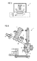
- FIG. 1 schematically shows a section of a device 1 for filling a container 100 with a filling product 110.
- the device 1 is formed in the example shown as a free-jet filler and comprises a filling valve 2 with a valve cone 20, which can be lowered sealingly into a valve seat 22 complementary thereto.
- the valve cone 20 is lifted in the direction indicated by the arrow opening direction 24 upwards out of the valve seat 22.
- the filling product 110 can flow around the valve cone 20 in such a way that the filling product 110 can flow out of a product outlet 200 into the container 100 arranged below it.
- arrows indicated in the filling product 110 describe the behavior of the filling product, for example a homogeneous liquid such as water, which passes through the filling valve 2.
- the filling product 110 can flow around the valve cone 20 homogeneously and correspondingly between the valve cone 20 and the valve seat 22, which is designed to be complementary to the valve cone 20, flow around homogeneously.
- FIG. 2 shows an example of the in FIG. 1 shown section of the device 1 with the filling valve 2 in a further state in which between the valve cone 20 and the valve seat 22, a particle 112, such as a piece of fruit, is clamped. Due to the trapped particle 112, there is a blockage of the outlet of the filling product 110 in this region of the filling valve 2. Accordingly, there is an asymmetric jet formation of the filling product jet below the filling valve 2, so that by the conical shape of the
- Valve seat 22 applied side-directed pulses on the filling product 110 no longer compensate each other. Accordingly, for example, a deviation of the filling product jet takes place such that a part of the filling product 110 meets an opening region 102 of the container 100 to be filled and accordingly contaminates with filling product. This can be particularly problematic if the filling product is suitable for causing mold growth or nucleation on the outside of the container 100 to be filled or of the mouth region. Accordingly, the in FIG. 2 shown situation, which is caused for example by the pinching of particles 112, can be avoided.
- spraying may also result from differential flow resistance of the homogeneous filler and particles.
- spraying may also result from differential flow resistance of the homogeneous filler and particles.
- the poppet 20 must be lifted out of the valve seat 22 to fully open the filling valve 2.
- the annular gap formed between the valve cone 20 and the valve seat 22 is not yet extended far enough to allow all the particles 112, for example all pieces of fruit, a smooth passage. Accordingly, the described spraying of the filling product 110 may occur in this opening phase.
- FIG. 3 shows a device 1 for filling a container, not shown, with a filling product, preferably for filling containers with a beverage in a beverage filling plant, which in turn has a filling valve 2 and by means of which the spraying can be reduced or avoided altogether.
- the filling valve 2 is part of a free-jet filler and comprises a valve cone 20, which is arranged in a corresponding, complementary valve seat 22.
- An actuation of the valve plug 20 is performed via an actuator 26, which may be, for example, a mechanical, electrical, (electro) magnetic, pneumatic or hydraulic actuator, which ensures raising or lowering of the valve plug 20 in the valve seat 22.
- the filling product outlet 200 is furthermore provided, through which the filling product flows out into the container to be filled.
- the Rail maybeausgang 200 is usually rotationally symmetrical to the valve cone 20 and the valve seat 22 is formed so that upon lifting of the valve plug 20, a completely symmetrical annular gap at Artisserausgang 200 is formed, through which the filling product can leak.
- the filling product 110 is arranged in a filling product reservoir 3, from which it is supplied to the filling valve 2 via a corresponding filling product line 30.
- a shut-off valve 4 is provided, by means of which the filling product line 30 can be completely shut off. Accordingly, the volume existing between the filling valve 2 and the shut-off valve 4 can be tightly sealed when both the shut-off valve 4 and the filling valve 2 are closed.
- a volume actuator 5 is provided, which can influence the volume provided between the shut-off valve 4 and the filling valve 2 in the supply line 30 and the filling valve 2.
- the volume actuator 5 By a corresponding actuation of the volume actuator 5, the volume provided between the shut-off valve 4 and the filling valve 2 is increased or reduced, depending on the actuation of the volume actuator 5.
- volume actuator 5 which is shown in the embodiment shown as laterally deflectable to the filling product flow membrane, the volume between the shut-off valve 4 and the filling valve 2 can be varied accordingly.
- an exemplary volume actuator 5 is shown having a diaphragm 50 which is reciprocable by a corresponding drive 52 between a first position 50a and a second position 50b.
- a corresponding drive 52 between the shut-off valve 4 and the Filling valve 2 arranged volume via actuation of the drive 52 to the switching volume V shown in dashed lines varies.
- the volume can be increased when the membrane 50 is moved from the position 50b in the position 50a.
- the switching volume V is added to the total volume between the shut-off valve 4 and the filling valve 2 and generates a negative pressure in this way.
- FIG. 4 shows a flow chart for opening and closing the respective valves or actuators to avoid a splash at the beginning of the filling process for filling containers with particle-containing filling product.
- the flowchart assumes that in the step 1, the shut-off valve 4 and the filling valve 2 are closed and the volume actuator 5 is present in the closed position. Before opening the shut-off valve 4, which only happens in the operating step 4, the volume actuator 5 is initially actuated in the operating step 2 in order to increase the volume in the space between the shut-off valve 4 and the filling valve 2 accordingly. This creates a vacuum in the volume.
- the filling valve 2 is fully opened. Due to the negative pressure applied by means of the volume actuator 5, the filling product is prevented from running out of the filling valve 2 immediately at the beginning of the opening process. This can prevent particles from jamming in the filling valve 2, which has not yet been completely opened.
- shut-off valve 4 Only after complete opening of the filling valve 2, the shut-off valve 4 is opened, so that a flow of the filling product from the filling product reservoir 3 is released.
- the volume present between the shut-off valve 4 and the filling valve 2 is first increased by the actuation of the volume actuator 5, thereby producing a negative pressure.
- the filling valve 2 is opened, wherein the negative pressure causes the filling product, which is present above the filling valve 2, not yet issued. Only then is the shut-off valve 4 opened, in order then to allow a flow through the supply line 30 and the filling valve 2 with the filling product 110, when the filling valve 2 is fully opened.
- an optional metering device 6 is provided, by means of which pieces of fruit or other particles can be added to the filling product.
- the metering device 6 is designed so that the corresponding particles are metered directly above the filling valve 2 or directly above the valve cone 20 and the valve seat 22.
- the use of the metering device 6 also has the advantage that in the region of the supply line 30, a flow meter can be used, by means of which the liquid to be metered can be measured. Such flowmeters are usually inaccurate when measuring inhomogeneous liquids. In the proposed embodiment, however, a volume measurement can be carried out, since above the metering device 6 only homogeneous filling product is introduced.
- volumenaktuator 5 also to avoid dripping, in particular to avoid dripping after completion of the filling.
- a negative pressure is applied such that between the shut-off valve 4 and the filling valve 2, a corresponding negative pressure ensures that a dripping of the filling product is avoided.
- FIG. 6 a further variant of a device 1 for filling containers is shown, again a Med.
- Arthur 30 is provided and volume actuators 5 ', 5 "and 5'" are provided.
- the first volume actuator 5 ' is similar to that in FIGS Figures 3 and 5 formed volume actuator, namely in the form of a laterally deflectable to Rail Crusherstrom membrane 50th
- a second volume actuator 5 is provided in the form of a conventional cylinder with a piston, by means of which a volume can be correspondingly increased or reduced.
- a third Volumenaktuator 5 '" is shown in the form of a compressible elastic membrane, which can change their volume by a linear displacement or upsetting.
- the volume actuators 5 ', 5 "and 5'” are arranged between a shut-off valve 4 and the corresponding filling valve 2.
- the different volume actuators 5 ', 5 ", 5'” are shown here merely by way of example in a single device 1, and, although all three volume actuators can also be arranged together in one embodiment, only one or two of the volume actuators shown can be provided.
- volume actuators 5 ', 5 "and 5'” it is achieved that the volume for the filling product can be increased after the end of the filling process, such that dripping due to the resulting negative pressure can be avoided. This is particularly important if, for example, pasty filling products are filled, such as ketchup.
- FIG. 7 shown embodiment of a filler carousel 70 of importance, in which corresponding containers to be filled via a feed 72 are supplied and discharged via a discharge 74 again.
- a dripping can lead to the corresponding system area being contaminated and filling product being wasted.
Abstract
Description
Die vorliegende Erfindung betrifft eine Vorrichtung sowie ein Verfahren zum Befüllen eines Behälters mit einem Füllprodukt, bevorzugt zum Befüllen eines Behälters mit einem Getränk in einer Getränkeabfüllanlage.The present invention relates to a device and a method for filling a container with a filling product, preferably for filling a container with a beverage in a beverage filling plant.
Es ist bekannt, in Vorrichtungen zum Abfüllen von Füllprodukten, beispielsweise zum Abfüllen von Getränken in einer Getränkeabfüllanlage, so genannte Freistrahlfüller zu verwenden, mittels welchen das jeweilige Füllprodukt aus einem über dem jeweiligen zu befüllenden Behälter anzuordnenden Füllproduktausgang in das Innere des Behälters eingebracht werden kann. Bei einem solchen Freistrahlfüller wird dies dadurch erreicht, dass nach dem Füllproduktausgang des Füllventils das jeweilige Füllprodukt unbeeinflusst von anderen Leitvorrichtungen, der Gravitation folgend, in den zu befüllenden Behälter strömt. Mit anderen Worten wird der Freistrahl, welcher sich nach dem Füllproduktausgang auch aufgrund der Oberflächenspannung des Füllproduktes ergibt, nicht weiter beeinflusst, sondern fällt unbeeinflusst in das Innere des zu befüllenden Behälters.It is known to use so-called free-jet fillers in devices for filling filling products, for example for bottling beverages in a beverage bottling plant, by means of which the respective filling product can be introduced from a filling product outlet to be arranged above the respective container to be filled into the interior of the container. In the case of such a free-jet filler, this is achieved in that, after the filling product outlet of the filling valve, the respective filling product flows into the container to be filled, uninfluenced by other guiding devices, following the gravitation. In other words, the free jet, which results after the Füllproduktausgang also due to the surface tension of the filling product, not further influenced, but falls unaffected in the interior of the container to be filled.
Bei einem solchen Freistrahlfüller wird als Füllventil häufig ein in einem Ventilsitz abdichtend angeordneter Ventilkegel verwendet, welcher mittig zum Füllproduktausgang angeordnet ist. Entsprechend wird der Ventilkegel beim Öffnen beziehungsweise Anheben symmetrisch von allen Seiten von dem Füllprodukt umströmt, so dass sich etwaige, durch die konusförmige Form des Ventilsitzes auftretende seitlich gerichtete Impulse des Füllproduktes gegenseitig aufheben, und sich damit ein genau unterhalb des Füllproduktausganges mittig auslaufender, gleichmäßiger Füllproduktstrahl ausbildet. Damit wird vom Füllbeginn bis zum Füllende bei homogenen Füllprodukten ein gleichmäßig auslaufender Füllstrahl erreicht.In such a free-jet filler is often used as a filling valve in a valve seat sealingly arranged valve cone, which is arranged centrally to Füllproduktausgang. Accordingly, the valve cone when opening or lifting is symmetrically flowed around from all sides by the filling product, so that any, arising from the conical shape of the valve seat laterally directed impulses of the filling cancel each other, and thus a just below the Füllproduktausganges centrally expiring, uniform Füllproduktstrahl formed. Thus, from the start of filling to the end of filling in homogeneous filling products, a uniformly flowing filling jet is achieved.
Bei der Abfüllung von Fruchtstücke oder Fruchtfasern enthaltenden Getränken kommt es jedoch vor, dass sich diese Fruchtstücke beziehungsweise Fruchtfasern in Füllpausen oberhalb des Ventilkegels und um diesen herum anlagern. Entsprechend kann es bei einem Öffnen des Ventilkegels zu einer Situation kommen, in welcher sich einzelne Fruchtstücke oder Fruchtfasern in dem Strömungskanal verklemmen, sie einen erhöhten Strömungswiderstand erzeugen, oder es zu einer asymmetrischen Pfropfenbildung kommt. Eine solche partielle Verstopfung beziehungsweise Pfropfenbildung führt während des Öffnungsvorganges des Füllventils dazu, dass sich entsprechend die einzelnen, durch den konischen Querschnitt des Füllventils auf die dann vereinzelten Flüssigkeitsströme aufgebrachten seitlichen Impulse nicht mehr gegeneinander aufheben. Entsprechend tritt zu Beginn der Öffnung des Füllventils eine seitliche Abweichung des Füllstrahls auf, welche dazu führen kann, dass ein Teil des Füllproduktes nicht berührungslos durch die Mündung in das zu befüllende Gefäß gelangt, sondern in andere Anlagenbereiche verspritzt wird, oder auf der Außenseite des zu befüllenden Behälters aufkommt. Solche Spritzer auf der Außenseite der Flasche sind nachteilig, da sie beispielsweise zu einer Keim- beziehungsweise Schimmelbildung auf der Flasche oder am Flaschengewinde führen können.When bottling fruit pieces or fruit fibers containing beverages, it happens, however, that these fruit pieces or fruit fibers accumulate in Füllpausen above the valve cone and around it. Accordingly, when the valve cone is opened, a situation may occur in which individual pieces of fruit or fruit fibers become jammed in the flow channel, produce an increased flow resistance, or an asymmetric plug formation occurs. During the opening process of the filling valve, such a partial blockage or plug formation causes the individual impulses applied by the conical cross section of the filling valve to be no longer counteracted against the then separated liquid streams. Accordingly occurs at the beginning of the opening of the filling valve, a lateral deviation of the filling jet, which can cause a portion of the filling product is not contactless passes through the mouth in the vessel to be filled, but is sprayed into other areas of the plant, or on the outside of filling container arises. Such splashes on the outside of the bottle are disadvantageous because they can lead, for example to a germ or mold on the bottle or on the bottle thread.
Das Problem solcher Spritzer kann auch zum Ende des Füllvorganges hin auftreten, nämlich dann, wenn sich beim Absenken des Ventilkegels in den Ventilsitz wiederum Fruchtstücke zwischen dem Ventilkegel und dem Ventilsitz verklemmen, welche dann wieder für einen asymmetrischen Strahlquerschnitt sorgen, der dann entsprechend der seitlich aufgebrachten Impulse zur Seite hin abgelenkt wird.The problem of such splattering can also occur towards the end of the filling process, namely when fruit pieces between the poppet and the valve seat jam when lowering the poppet in the valve seat, which then again provide an asymmetric jet cross-section, which then applied according to the side Impulse is deflected to the side.
Der Stand der Technik hat sich mit dieser Problematik bereits beschäftigt. So ist beispielsweise aus der
Ausgehend von diesem bekannten Stand der Technik ist es eine Aufgabe der vorliegenden Erfindung, eine Vorrichtung zum Befüllen eines Behälters mit einem Füllprodukt anzugeben, bei welchem das Auftreten von Spritzern noch effektiver unterbunden wird.Starting from this known prior art, it is an object of the present invention to provide an apparatus for filling a container with a filling product, in which the occurrence of splashes is even more effectively prevented.
Diese Aufgabe wird durch eine Vorrichtung zum Befüllen eines Behälters mit einem Füllprodukt mit den Merkmalen des Anspruchs 1 gelöst. Vorteilhafte Weiterbildungen ergeben sich aus den Unteransprüchen.This object is achieved by a device for filling a container with a filling product with the features of
Entsprechend wird eine Vorrichtung zum Befüllen eines Behälters mit einem Füllprodukt, bevorzugt zum Befüllen eines Behälters mit einem Getränk in einer Getränkeabfüllanlage, vorgeschlagen, umfassend ein Füllventil zum Einbringen eines Füllproduktstromes in einen zu befüllenden Behälter, und ein stromaufwärts des Füllventils im Füllproduktstrom angeordnetes Absperrventil zum Absperren des Füllproduktstromes zum Füllventil. Erfindungsgemäß ist ein Volumenaktuator zum Erhöhen und/oder Reduzieren des zwischen Füllventil und Absperrventil vorgesehenen Volumens vorgesehen.Accordingly, an apparatus for filling a container with a filling product, preferably for filling a container with a beverage in a beverage filling plant, is proposed, comprising a filling valve for introducing a Füllproduktstromes into a container to be filled, and upstream of the filling valve in the Füllproduktstrom arranged shut-off valve for shutting off the filling product flow to the filling valve. According to the invention, a volume actuator is provided for increasing and / or reducing the volume provided between the filling valve and the shut-off valve.
Durch den Volumenaktuator zum Erhöhen und/oder Reduzieren des Volumens zwischen Füllventil und Absperrventil kann erreicht werden, dass vor dem Öffnen des Füllventils der Füllproduktdruck zwischen dem Absperrventil und dem Füllventil reduziert wird, um ein vorzeitiges Auslaufen des Füllproduktes zu verhindern. Der Füllproduktstrom wird erst dann gestartet, wenn das Füllventil vollständig geöffnet ist. Entsprechend wird ein Verspritzen des Füllproduktes während des Öffnungsvorganges des Füllventils verringert oder verhindert. Dies ist insbesondere auch dann der Fall, wenn das Füllprodukt Partikel, wie beispielsweise Fruchtstücke, enthält, so dass auf diese Weise ein Spritzen beim Öffnen des Füllventils vermieden werden kann.By means of the volume actuator for increasing and / or reducing the volume between the filling valve and the shut-off valve, it is possible to reduce the filling product pressure between the shut-off valve and the filling valve before opening the filling valve in order to prevent premature leakage of the filling product. The filling product flow is only started when the filling valve is fully opened. Accordingly, splashing of the filling product during the opening process of the filling valve is reduced or prevented. This is especially the case when the filling product contains particles, such as fruit pieces, so that in this way a spraying when opening the filling valve can be avoided.
Gleichermaßen kann durch den Volumenaktuator auch ein Spritzen beim Schließen des Füllventils verhindert werden, insbesondere dadurch, dass das Füllprodukt vor dem Schließen des Füllventils durch den Volumenaktuator quasi zurückgesaugt wird, so dass auch hier ein Spritzen vermieden werden kann und ein zuverlässiges Schließen des Füllventils ohne Spritzer erreicht werden kann.Similarly, by the Volumenaktuator also a spraying when closing the filling valve can be prevented, in particular by the fact that the filling product is virtually sucked back by the Volumenaktuator before closing the filling valve, so that even here a spraying can be avoided and a reliable closing of the filling valve without splashing can be achieved.
Weiterhin kann durch das Bereitstellen des Volumenaktuators ein Nachtropfen des Füllproduktes auch dann vermieden werden, wenn kein zu befüllender Behälter mehr unter demFurthermore, by providing the Volumenaktuators a dripping of the filling product can be avoided even if no container to be filled under the
Füllproduktausgang angeordnet ist, da ein Unterdruck in das stromaufwärts des Füllventils liegende Volumen eingebracht werden kann. Auf diese Weise kann das Nachtropfen insbesondere in den Anlagenbereichen verringert beziehungsweise vermieden werden, in welchen nachtropfendes Füllprodukt nicht von einem zu befüllenden Behälter aufgenommen wird. Dies ist insbesondere in einem Bereich zwischen einem Behältereinlauf und einem Behälterauslauf, beispielsweise eines Füllerkarussells, hilfreich, da hier nach der Übergabe des befüllten Behälters üblicherweise noch ein Nachtropfen stattfinden kann, die jeweiligen Zeitpunkte des Nachtropfens jedoch nicht vorhersehbar sind. Durch die Erzeugung eines Unterdrucks in der Zuleitung zu dem Füllventil beziehungsweise durch das Zurückziehen des am Füllventil anstehenden Füllproduktes kann entsprechend ein Nachtropfen verhindert werden. Insbesondere ist dies von Bedeutung, wenn Füllprodukte mit Partikeln, beispielsweise mit Fruchtstücken, abgefüllt werden, da hier bereits beim Schließvorgang des Füllventils für ein sauberes Abdichten des Ventilkegels im Ventilsitz gesorgt werden kann.Füllproduktausgang is arranged, since a negative pressure in the upstream of the filling valve volume can be introduced. In this way, the dripping can be reduced or avoided in particular in the plant areas, in which dripping waste product is not absorbed by a container to be filled. This is helpful in particular in a region between a container inlet and a container outlet, for example a filler carousel, since here after the transfer of the filled container usually a dripping may take place, but the respective times of the dripping are not foreseeable. By generating a negative pressure in the supply line to the filling valve or by the withdrawal of the filling valve pending on the filling product can accordingly be prevented dripping. In particular, this is important when filling products with particles, such as pieces of fruit, are filled, since already here during the closing of the filling valve for a clean sealing of the valve cone can be ensured in the valve seat.
Weiterhin kann durch den Volumenaktuator auch ein kurzfristig auf das Füllproduktvolumen aufgebrachter Überdruck, welcher durch das Anheben des Ventilkegels in Verbindung mit der Oberflächenspannung des Füllprodukts auftreten kann, ausgeglichen werden. Auch aufgrund dieses Ausgleichs kann die Spritzneigung reduziert werden.Furthermore, by the volume actuator also a short-term applied to the Füllproduktvolumen overpressure, which may occur by raising the valve cone in conjunction with the surface tension of the filling product, be compensated. Also due to this balance, the tendency to spatter can be reduced.
In einem bevorzugten Ausführungsbeispiel ist der Volumenaktuator beispielsweise in Form eines Zylinders oder einer betätigbaren Membran, welche beispielsweise translatorisch oder lateral bezüglich des Füllproduktstroms auslenkbar ist, vorgesehen. So kann auf einfache Weise das Bereitstellen einer entsprechenden Volumenreduktion beziehungsweise einer entsprechenden Volumenerweiterung erreicht werden, beispielsweise durch die Betätigung des entsprechenden Zylinders oder der entsprechenden Membran, so dass auf eine zuverlässige Weise die Vorrichtung betätigt werden kann. Dies ist insbesondere im Zusammenhang mit den erforderlichen Schaltzeiten von Bedeutung, da zur Betätigung der Gesamtvorrichtung entsprechend ein schnell betätigbarer Volumenaktuator von Vorteil ist. In einer weiteren Variante kann auch eine in Richtung des Fluidstroms stauchbare Membran vorgesehen sein, mittels welcher das Volumen reduziert oder erhöht werden kann.In a preferred exemplary embodiment, the volume actuator is provided, for example, in the form of a cylinder or an actuatable membrane which, for example, can be deflected translationally or laterally with respect to the product flow of the product. Thus, the provision of a corresponding volume reduction or a corresponding volume expansion can be achieved in a simple manner, for example by the actuation of the corresponding cylinder or the corresponding membrane, so that the device can be actuated in a reliable manner. This is particularly important in connection with the required switching times of importance, since to actuate the overall device according to a rapidly operable volume actuator is advantageous. In a further variant, it is also possible to provide a membrane which can be compressed in the direction of the fluid flow, by means of which the volume can be reduced or increased.
Es ist bevorzugt, den Volumenaktuator zwischen dem Füllventil und dem Absperrventil anzuordnen, um eine zuverlässige Variation des Volumens zu erreichen.It is preferable to arrange the volume actuator between the filling valve and the shut-off valve to achieve a reliable variation of the volume.
Besonders bevorzugt ist eine Steuervorrichtung zur Steuerung des Absperrventils und des Volumenaktuators vorgesehen, welche eine entsprechende Betätigung des Volumenaktuators ermöglicht, bevor das Füllventil geöffnet wird beziehungsweise bevor das Füllventil geschlossen wird. Besonders bevorzugt ist die Steuervorrichtung so ausgebildet, dass sie zunächst das Absperrventil verschließt, um ein abgeschlossenes Volumen zwischen dem Absperrventil und dem Füllventil bereitzustellen. Darauf folgend wird mit dem Volumenaktuator das Volumen in diesem Bereich vergrößert, derart, dass auf diese Weise auch gleichzeitig eine Druckreduktion stattfindet. Daraufhin wird das Füllventil vollständig geöffnet, und erst dann das Absperrventil geöffnet. Auf diese Weise wird erreicht, dass ein Füllproduktstrom erst dann durch das Füllventil hindurch strömen kann, wenn ich das Füllventil in einer vollständig geöffneten Position befindet. In der vollständig geöffneten Position ist das Füllventil jedoch so ausgebildet, dass der Spalt zwischen dem Ventilkegel und dem Ventilsitz ausreichend dafür ist, dass sämtliche zugeführten und mit dem Füllprodukt mit bewegten Partikel problemlos hindurch passieren können. Auf diese Weise wird erreicht, dass der Füllproduktstrahl, welcher unterhalb des Füllventils und insbesondere unterhalb des Füllproduktausganges des Füllventils aus dem Füllventil ausströmt, die gewünschte Strahlform aufweist, da der Ventilkegel des Füllventils um seinen ganzen Umfang herum gleichmäßig von dem Füllprodukt umströmt wird. Entsprechend heben sich wieder die über den konischen Ventilsitz eingebrachten Impulse auf, so dass ein gleichmäßiger und spritzfreier Abfüllvorgang erreicht wird.Particularly preferred is a control device for controlling the shut-off valve and the volume actuator is provided, which allows a corresponding actuation of the Volumenaktuators before the filling valve is opened or before the filling valve is closed. Particularly preferably, the control device is designed such that it initially closes the shut-off valve in order to provide a closed volume between the shut-off valve and the filling valve. Following this, the volume in this area is increased with the volume actuator, such that a pressure reduction also takes place in this way at the same time. Then the filling valve is fully opened, and only then opened the shut-off valve. In this way it is achieved that a filling product flow can only flow through the filling valve when I am in the filling valve in a fully open position. In the fully open position, however, the filling valve is formed so that the gap between the valve plug and the valve seat is sufficient for all supplied and easily passed through with the moving particles with the product. In this way it is achieved that the filling product jet, which flows out of the filling valve below the filling valve and in particular below the filling product output of the filling valve, has the desired jet shape, since the valve cone of the filling valve is uniformly flowed around its entire periphery around by the filling product. Correspondingly, the impulses introduced via the conical valve seat lift up again, so that a uniform and injection-free filling process is achieved.
Die Steuervorrichtung ist weiterhin bevorzugt so ausgebildet, dass sie beim Beendigen des Abfüllvorganges zunächst das Absperrventil betätigt, um den Flüssigkeitsstrom zu unterbrechen. Dann wird der Volumenaktuator so betätigt, dass das Volumen zwischen dem Absperrventil und dem Füllventil vergrößert wird, was darin resultiert, dass das Füllprodukt leicht zurückgezogen wird und insbesondere ein Unterdruck entsteht. Daraufhin erst wird das Füllventil vollständig geschlossen. Auf diese Weise wird erreicht, dass der Füllproduktstrom nicht durch das eigentliche Füllventil beendet wird, wodurch ein Einklemmen von einzelnen Partikeln, beispielsweise einzelnen Fruchtstücken zwischen dem Ventilkegel und dem Ventilsitz, auftreten könnte. Vielmehr kann durch die Steuerung das Füllprodukt so lange aus dem Füllventil auslaufen, bis die inneren Druckverhältnisse ein weiteres Nachlaufen des Füllproduktes unterbinden. Dann wird durch das Rückziehen des Füllproduktes aufgrund der Volumenerweiterung mittels des Volumenaktuators ein störungsfreies Verschließen des Füllventils möglich.The control device is furthermore preferably designed such that it first actuates the shut-off valve at the end of the filling process in order to interrupt the liquid flow. Then, the volume actuator is operated to increase the volume between the shut-off valve and the filling valve, resulting in that the filling product is easily withdrawn and, in particular, a vacuum is created. Only then is the filling valve completely closed. In this way it is achieved that the filling product flow is not terminated by the actual filling valve, whereby pinching of individual particles, for example individual pieces of fruit between the valve cone and the valve seat, could occur. Rather, by the controller, the filling product so long from the filling valve leak until the internal pressure conditions prevent further lagging of the filling product. Then, by the withdrawal of the filling product due to the volume expansion by means of the Volumenaktuators a trouble-free closing of the filling valve possible.
Weiterhin kann auch nach dem eigentlichen Schließvorgang des Füllventils eine Volumenerweiterung durch eine entsprechende Betätigung des Volumenaktuators erreicht werden, derart, dass ein Unterdruck zwischen dem Absperrventil und dem Füllventil vorliegt und entsprechend ein Nachtropfen noch wirkungsvoller unterbunden werden kann.Furthermore, even after the actual closing operation of the filling valve, a volume expansion can be achieved by a corresponding actuation of the volume actuator, such that there is a negative pressure between the shut-off valve and the filling valve and, correspondingly, dripping can be prevented even more effectively.
In einem besonders bevorzugten Ausführungsbeispiel ist eine Zudosiervorrichtung zum Zudosieren von Partikeln, bevorzugt zum Zudosieren von Fruchtpulpe oder Fruchtstücken, vor dem Füllventil vorgesehen, bevorzugt zwischen dem Füllventil und dem Volumenaktuator, besonders bevorzugt direkt vor dem Füllventil. Auf diese Weise kann in den Füllpausen der entsprechende Partikel tragende Anteil des Füllprodukts direkt auf das Füllventil aufgegeben werden und dann, nach vollständiger Öffnung des Füllventils und vorhergehender Volumenerweiterung beziehungsweise Unterdruckerzeugung durch den Volumenaktuator, vollständig mittels des durch das Absperrventil freigegebenen Füllprodukts ausgespült werden. Auf diese Weise lässt sich, auch in Verbindung mit einem Volumenmesser, eine Abfüllung erreichen, welche exakt ein bestimmtes Füllvolumen in den zu befüllenden Behälter einfüllt. Insbesondere lässt sich eine exakte Volumenmessung auf diese Weise dann durchführen, wenn die Zudosiervorrichtung nach dem Volumenmesser angeordnet ist. Der Volumenmesser wird entsprechend nicht durch hindurchtretende Partikel irritiert, sondern kann ein homogenes Füllprodukt messen. Die entsprechende Vorrichtung ist besonders geeignet zur Abfüllung von Fruchtsäften mit Fruchtfasern beziehungsweise Fruchtstücken beziehungsweise zum Abfüllen von leicht pastösen Lebensmitteln, wie beispielsweise Joghurt mit Fruchtstücken. Auf diese Weise kann eine sehr exakte Abfüllung mit entsprechend großen Fruchtstücken erreicht werden, beispielsweise können auf diese Weise Fruchtstücke auch von einer Größe von ungefähr 10x10x10 mm als Saftzusatz abgefüllt werden.In a particularly preferred embodiment, a metering device for metering in particles, preferably for metering fruit pulp or pieces of fruit, is provided in front of the filling valve, preferably between the filling valve and the volume actuator, particularly preferably directly in front of the filling valve. In this way, in the filling intervals of the corresponding particle-carrying portion of the filling product can be applied directly to the filling valve and then, after complete opening of the filling valve and previous volume expansion or vacuum generation by the Volumenaktuator, completely flushed by means of the released through the shut-off filling product. In this way, a filling can be achieved, also in conjunction with a volume meter, which fills exactly a certain filling volume in the container to be filled. In particular, an exact volume measurement can be carried out in this way if the metering device is arranged downstream of the volume meter. The volume meter is correspondingly not irritated by passing particles, but can measure a homogeneous filling product. The corresponding device is particularly suitable for filling of fruit juices with fruit fibers or pieces of fruit or for filling slightly pasty foods, such as yogurt with fruit pieces. In this way, a very accurate filling with correspondingly large pieces of fruit can be achieved, for example, fruit pieces can also be filled in this way of a size of about 10x10x10 mm as a juice additive.
Die Steuervorrichtung ist weiterhin so ausgebildet, dass sie den Volumenaktuator während des eigentlichen Füllvorgangs wieder in eine Ausgangsposition zurück bringt, um beim nachfolgenden Verschließen und/oder Öffnen des Füllventils wieder die geforderte Volumenvariation bereit stellen zu können.The control device is furthermore designed such that it brings the volume actuator back into a starting position during the actual filling process in order to be able to provide the required volume variation again during the subsequent closing and / or opening of the filling valve.
Die oben genannte Aufgabe wird weiterhin auch durch ein Verfahren mit den Merkmalen des Anspruchs 10 gelöst. Vorteilhafte Weiterbildungen ergeben sich aus den Unteransprüchen.The above object is further achieved by a method having the features of claim 10. Advantageous developments emerge from the subclaims.
Entsprechend wird ein Verfahren zum Befüllen eines Behälters mit einem Füllprodukt, bevorzugt zum Befüllen eines Behälters mit einem Getränk in einer Getränkeabfüllanlage, vorgeschlagen, umfassend das Einbringen eines Füllproduktstromes in den zu befüllenden Behälter über ein Füllventil. Erfindungsgemäß wird vor dem Öffnen oder Schließen des Füllventils ein Unterdruck oder ein Überdruck auf das stromaufwärts zum Füllventil anstehende Füllprodukt aufgebracht.Accordingly, a method for filling a container with a filling product, preferably for filling a container with a beverage in a beverage filling plant, is proposed, comprising the introduction of a filling product stream into the container to be filled via a Filling valve. According to the invention, a negative pressure or an overpressure is applied to the filling product upstream of the filling valve before the filling valve is opened or closed.
Dadurch, dass beispielsweise vor dem Öffnen des Füllventils ein Unterdruck entsprechend aufgebracht wird, kann die Neigung des Füllventils zum Spritzen während des Öffnungsvorganges des Füllventils reduziert beziehungsweise vollständig unterbunden werden. Wie oben beschrieben kann auf diese Weise erreicht werden, dass ein gleichmäßiges Abfüllen des Füllproduktes erreicht wird, ohne dass ein Spritzen auftritt, da der Füllproduktstrom erst dann das Füllventil durchströmt, wenn das Füllventil vollständig geöffnet ist. Insbesondere beim Abfüllen von mit Partikeln beladenen Füllprodukten kann auf diese Weise eine asymmetrische Strahlausbildung vermieden werden und entsprechend ein Spritzen und auch ein Nachtropfen beim nachfolgenden Verschließvorgang vermieden werden.Characterized in that, for example, before opening the filling valve, a negative pressure is applied accordingly, the inclination of the filling valve for spraying during the opening process of the filling valve can be reduced or completely prevented. As described above can be achieved in this way that a uniform filling of the filling product is achieved without a spraying occurs because the Füllproduktstrom only flows through the filling valve when the filling valve is fully open. In particular, during the filling of loaded with particles filling products in this way an asymmetric jet formation can be avoided and accordingly a splash and a dripping during the subsequent closing process can be avoided.
Weiterhin wird, insbesondere beim Vorsehen eines herkömmlichen Ventils mit einem Ventilkegel und einem entsprechend konusförmig ausgebildeten Ventilsitz üblicherweise beim Öffnen dieses Ventils ein leichter Überdruck innerhalb des darüberstehenden Produktvolumens erzeugt. Dieser leichte Überdruck wird auch über den Volumenaktuator abgefangen beziehungsweise überkompensiert, derart, dass das oberhalb des Ventilkegels anstehende Füllprodukt zurückgezogen wird und entsprechend ein Spritzen vermieden wird.Furthermore, especially when providing a conventional valve with a poppet and a corresponding cone-shaped valve seat is usually generated when opening this valve, a slight overpressure within the above product volume. This slight overpressure is also intercepted or overcompensated via the volume actuator, such that the filling product present above the valve cone is withdrawn and, accordingly, spraying is avoided.
Um ein Spritzen beim Öffnen zu reduzieren oder zu unterbinden wird bevorzugt vor dem Öffnen des Füllventils zunächst ein stromaufwärts des Füllventils angeordnetes Absperrventil geschlossen, und dann mittels eines Volumenaktuators das zwischen dem Füllventil und dem Absperrventil vorliegende Volumen zur Erzeugung des Unterdrucks auf das Füllprodukt erhöht.In order to reduce or prevent spraying during opening, a shut-off valve arranged upstream of the filling valve is preferably closed before opening the filling valve, and then increases the volume present between the filling valve and the shut-off valve by means of a volume actuator for generating the negative pressure on the filling product.
Ein Spritzen beim Verschließen lässt sich reduzieren oder unterbinden wenn bevorzugt vor dem Schließen des Füllventils zunächst ein stromaufwärts des Füllventils angeordnetes Absperrventil geschlossen wird und dann mittels eines Volumenaktuators das zwischen dem Füllventil und dem Absperrventil liegende Volumen vergrößert wird, bevorzugt zum Zurückziehen des Füllprodukts.A syringe during closing can be reduced or prevented if, preferably before closing the filling valve, a shut-off valve arranged upstream of the filling valve is closed and then the volume between the filling valve and the shut-off valve is increased by means of a volume actuator, preferably for retraction of the filling product.
Um einen kontinuierlichen Befüllbetrieb aufrecht halten zu können, wird bevorzugt ein Volumenaktuator während des eigentlichen Befüllvorganges wieder in seine Ausgangsposition überführt.In order to be able to maintain a continuous filling operation, a volume actuator is preferably transferred back to its starting position during the actual filling process.
Bevorzugte weitere Ausführungsformen und Aspekte der vorliegenden Erfindung werden durch die nachfolgende Beschreibung der Figuren näher erläutert. Dabei zeigen:
Figur 1- eine schematische Darstellung eines Ausschnitts eines Freistrahlfüllers mit einem Füllproduktausgang zum Befüllen eines zu befüllenden Behälters mit einem Füllprodukt unter Ausbildung eines symmetrischen Füllproduktstrahls;
Figur 2- den Ausschnitt des Freistrahlfüllers aus
Figur 1 in einem Zustand, in welchem aufgrund einer teilweisen Blockade des Füllventils ein asymmetrischer Füllproduktstrahl ausgebildet wird; Figur 3- eine schematische Darstellung einer Vorrichtung zum Befüllen eines Behälters mit einem Füllprodukt gemäß einem ersten Ausführungsbeispiel;
Figur 4- eine Ablauftabelle für die Schaltung der Ventile und des Volumenaktuators in der Vorrichtung gemäß
Figur 3 ; Figur 5- eine schematische Darstellung eines exemplarischen Ausführungsbeispiels eines Volumenaktuators;
- Figur 6
- eine schematische Darstellung einer Vorrichtung zum Befüllen eines Behälters mit einem Füllprodukt in einem weiteren Ausführungsbeispiel, in welchem exemplarisch unterschiedliche Volumenaktuatoren vorgesehen sind; und
- Figur 7
- eine schematische Darstellung eines Füllerkarussells mit einem Einlaufbereich und einem Auslaufbereich für die zu befüllenden Behälter.
- FIG. 1
- a schematic representation of a section of a free-jet filler with a Füllproduktausgang for filling a container to be filled with a filling product to form a symmetrical Füllproduktstrahls;
- FIG. 2
- the cutout of the free-jet filler
FIG. 1 in a state in which due to a partial blockage of the filling valve, an asymmetric Füllproduktstrahl is formed; - FIG. 3
- a schematic representation of an apparatus for filling a container with a filling product according to a first embodiment;
- FIG. 4
- a flow chart for the circuit of the valves and the Volumenaktuators in the apparatus according to
FIG. 3 ; - FIG. 5
- a schematic representation of an exemplary embodiment of a volume actuator;
- FIG. 6
- a schematic representation of an apparatus for filling a container with a filling product in a further embodiment, in which different volume actuators are provided by way of example; and
- FIG. 7
- a schematic representation of a filler carousel with an inlet region and an outlet region for the container to be filled.
Im Folgenden werden bevorzugte Ausführungsbeispiele anhand der Figuren beschrieben. Dabei werden gleiche, ähnliche oder gleichwirkende Elemente in den unterschiedlichen Figuren mit identischen Bezugszeichen bezeichnet und auf eine wiederholte Beschreibung dieser Elemente wird in der nachfolgenden Beschreibung teilweise verzichtet, um Redundanzen zu vermeiden.In the following, preferred embodiments will be described with reference to the figures. The same, similar or equivalent elements in the different figures with denoted by identical reference numerals and a repeated description of these elements will be omitted in the following description in part in order to avoid redundancies.
Die in
Ventilsitzes 22 aufgebrachten seitlich gerichteten Impulse auf das Füllprodukt 110 nicht mehr gegenseitig ausgleichen. Entsprechend findet beispielsweise eine Abweichung des Füllproduktstrahles so statt, dass ein Teil des Füllproduktes 110 einen Mündungsbereich 102 des zu befüllenden Behälters 100 trifft und entsprechend mit Füllprodukt kontaminiert. Dies kann besonders dann problematisch sein, wenn das Füllprodukt dazu geeignet ist, eine Schimmelbildung oder Keimbildung auf der Außenseite des zu befüllenden Behälters 100 oder des Mündungsbereichs hervorzurufen. Entsprechend soll die in
Neben einem tatsächlichen Einklemmen kann ein Spritzen auch durch unterschiedliche Fließwiderstände des homogenen Füllprodukts und der Partikel herrühren. Hier wird aus Gründen der Übersichtlichkeit immer von Einklemmen gesprochen - ein durch einen Partikel erzeugter höherer Fließwiderstand wird darunter aber auch verstanden.In addition to actual pinching, spraying may also result from differential flow resistance of the homogeneous filler and particles. Here, for reasons of clarity, there is always talk of pinching - but a higher flow resistance generated by a particle is also understood to mean this.
Die Partikel 112 verklemmen sich dabei zwischen dem Ventilkegel 20 und dem Ventilsitz 22 insbesondere zu Beginn des Öffnungsvorganges des Füllventils 2, da dann die vollständige Ausdehnung des ringförmigen Spalts zwischen Ventilkegel 20 und Ventilsitz 22 noch nicht erreicht wurde. Weiterhin sind die Anlagerungen der Partikel 112 im Bereich des Ventilkegels 20 zu Beginn des Öffnungsvorganges noch nicht durch den Füllproduktstrom fortgespült worden, wodurch ebenfalls ein Verklemmen beziehungsweise Blockieren wahrscheinlich ist.The
Der Ventilkegel 20 muss aus dem Ventilsitz 22 heraus angehoben werden, um das Füllventil 2 vollständig zu öffnen. In dieser Anfangsphase ist aber der zwischen dem Ventilkegel 20 und dem Ventilsitz 22 entstehende Ringspalt noch nicht weit genug ausgedehnt, um sämtlichen Partikeln 112, beispielsweise sämtlichen Fruchtstücken, einen reibungslosen Durchlass zu ermöglichen. Entsprechend kann es in dieser Öffnungsphase zu dem beschriebenen Spritzen des Füllprodukts 110 kommen.The
Das Füllventil 2 ist Teil eines Freistrahlfüllers und umfasst einen Ventilkegel 20, welcher in einem entsprechenden, dazu komplementären Ventilsitz 22 angeordnet ist. Eine Betätigung des Ventilkegels 20 wird über eine Betätigungsvorrichtung 26 durchgeführt, welche beispielsweise ein mechanischer, elektrischer, (elektro)magnetischer, pneumatischer oder hydraulischer Aktuator sein kann, welcher für ein Anheben beziehungsweise Absenken des Ventilkegels 20 in den Ventilsitz 22 sorgt.The filling
Im Bereich des Ventilkegels 20 ist weiterhin auch der Füllproduktausgang 200 vorgesehen, durch welchen hindurch das Füllprodukt in den zu befüllenden Behälter ausströmt. Der Füllproduktausgang 200 ist üblicherweise rotationssymmetrisch zum Ventilkegel 20 sowie zum Ventilsitz 22 ausgebildet, so dass bei einem Anheben des Ventilkegels 20 ein vollständig symmetrischer Ringspalt am Füllproduktausgang 200 entsteht, durch welchen hindurch das Füllprodukt auslaufen kann.In the area of the
Das Füllprodukt 110 ist in einem Füllproduktreservoir 3 angeordnet, von welchem aus es über eine entsprechende Füllproduktleitung 30 dem Füllventil 2 zugeführt wird. Zwischen dem Füllventil 2 und dem Füllproduktreservoir 3 ist ein Absperrventil 4 vorgesehen, mittels welchem die Füllproduktleitung 30 vollständig abgesperrt werden kann. Entsprechend kann das zwischen dem Füllventil 2 und dem Absperrventil 4 vorhandene Volumen dicht abgeschlossen werden, wenn sowohl das Absperrventil 4 als auch das Füllventil 2 verschlossen sind.The filling
Zwischen dem Absperrventil 4 und dem Füllventil 2 ist ein Volumenaktuator 5 vorgesehen, welcher das zwischen dem Absperrventil 4 und dem Füllventil 2 in der Zuführleitung 30 sowie dem Füllventil 2 vorgesehene Volumen beeinflussen kann. Durch eine entsprechende Betätigung des Volumenaktuators 5 wird damit das zwischen dem Absperrventil 4 und dem Füllventil 2 vorgesehene Volumen vergrößert oder reduziert -je nach Betätigung des Volumenaktuators 5.Between the shut-off
Mittels des Volumenaktuators 5, welcher in dem gezeigten Ausführungsbeispiel als lateral zum Füllproduktstrom auslenkbare Membran dargestellt ist, kann entsprechend das Volumen zwischen dem Absperrventil 4 und dem Füllventil 2 variiert werden.By means of the
In
Abhängig von der Ausgangsstellung der Membran 50 beim Schließen des in
Bei einer anderen Ausgangslage, in welcher die Membran 50 beim Verschließen des Absperrventils 4 sowie des Füllventils 2 in der Position 50a ist, kann das Gesamtvolumen zwischen dem Absperrventil 4 und dem Füllventil 2 durch eine Betätigung des Antriebs 52 um das Schaltvolumen V reduziert werden, wenn die Membran 50 von der Position 50a in die Position 50b überführt wird. Entsprechend wird ein Überdruck erzeugt.In another starting position, in which the
Das Ablaufdiagramm geht davon aus, dass im Ablaufschritt 1 das Absperrventil 4 und das Füllventil 2 geschlossen sind und der Volumenaktuator 5 in der geschlossenen Position vorliegt. Vor dem Öffnen des Absperrventils 4, welches erst im Ablaufschritt 4 geschieht, wird zunächst im Ablaufschritt 2 der Volumenaktuator 5 betätigt, um entsprechend das Volumen in dem Raum zwischen dem Absperrventil 4 und dem Füllventil 2 zu vergrößern. Dadurch wird ein Unterdruck in dem Volumen erzeugt.The flowchart assumes that in the
Dann wird im Ablaufschritt 3 das Füllventil 2 vollständig geöffnet. Aufgrund des mittels des Volumenaktuators 5 aufgebrachten Unterdrucks wird verhindert, dass das Füllprodukt sofort zum Beginn des Öffnungsvorganges aus dem Füllventil 2 herausläuft. Damit kann verhindert werden, dass sich Partikel in dem noch nicht vollständig geöffneten Füllventil 2 verklemmen.Then, in the
Erst nach vollständiger Öffnung des Füllventils 2 wird das Absperrventil 4 geöffnet, so dass ein Strom des Füllprodukts aus dem Füllproduktreservoir 3 freigegeben wird.Only after complete opening of the filling
Durch diese Abläufe wird erreicht, dass, ausgehend von einem geschlossenen Absperrventil 4 und einem geschlossenen Füllventil 2, zunächst durch die Betätigung des Volumenaktuators 5 das zwischen dem Absperrventil 4 und dem Füllventil 2 vorliegende Volumen vergrößert wird und dadurch ein Unterdruck erzeugt wird. Als nächstes wird das Füllventil 2 geöffnet, wobei der Unterdruck dazu führt, dass das Füllprodukt, welches über dem Füllventil 2 ansteht, noch nicht ausgegeben wird. Erst danach wird das Absperrventil 4 geöffnet, um dann ein Durchströmen der Zuführleitung 30 sowie des Füllventils 2 mit dem Füllprodukt 110 zu ermöglichen, wenn das Füllventil 2 vollständig geöffnet ist.Through these processes it is achieved that, starting from a closed shut-off
In
Die Verwendung der Zudosiervorrichtung 6 hat weiterhin den Vorteil, dass im Bereich der Zuführleitung 30 ein Durchflussmesser verwendet werden kann, mittels welchem die zu dosierende Flüssigkeit gemessen werden kann. Solche Durchflussmesser sind üblicherweise dann ungenau, wenn inhomogene Flüssigkeiten gemessen werden. Bei dem vorgeschlagenen Ausführungsbeispiel kann jedoch eine Volumenmessung durchgeführt werden, da oberhalb der Zudosiervorrichtung 6 lediglich homogenes Füllprodukt eingeleitet wird.The use of the metering device 6 also has the advantage that in the region of the
Beim nachfolgenden Verschließen des Füllventils 2 wird entsprechend in einer nahezu umgekehrten Reihenfolge verfahren, wobei zuerst mittels des Absperrventils 4 der Füllproduktstrom unterbrochen wird, dann mittels des Volumenaktuators 5 das Füllprodukt quasi aus dem Füllventil 2 zurückgesaugt wird, und dann erst das Füllventil 2 durch Absenken des Ventilkegels 20 in den Ventilsitz 22 geschlossen wird. Auf diese Weise kann ein Spritzen aufgrund einer möglichen Blockade eines bestimmten Ringabschnittes zwischen Ventilkegel 20 und Ventilsitz 22 vermieden werden. Vielmehr kann der Ventilkegel 20 dann problemlos in den Ventilsitz 22 abgesenkt werden, ohne dass es zu einem Spritzen kommt.During the subsequent closing of the filling
Weiterhin ist es möglich, den Volumenaktuator 5 auch zur Vermeidung des Nachtropfens zu verwenden, insbesondere zum Vermeiden des Nachtropfens nach Abschließen des Befüllvorganges. Hierzu wird nach dem Verschließen des Füllventils 2 ein Unterdruck derart aufgebracht, dass zwischen dem Absperrventil 4 und dem Füllventil 2 ein entsprechender Unterdruck dafür sorgt, dass ein Heraustropfen des Füllproduktes vermieden wird.Furthermore, it is possible to use the
In
Der erste Volumenaktuator 5' ist ähnlich zu dem in den
Ein zweiter Volumenaktuator 5" ist in Form eines herkömmlichen Zylinders mit einem Kolben vorgesehen, mittels welchem entsprechend ein Volumen vergrößert beziehungsweise verkleinert werden kann.A
Ein dritter Volumenaktuator 5'" ist in Form einer stauchbaren elastischen Membran gezeigt, welche durch eine Linearverschiebung beziehungsweise ein Stauchen ihr Volumen verändern kann.A third Volumenaktuator 5 '"is shown in the form of a compressible elastic membrane, which can change their volume by a linear displacement or upsetting.
Die Volumenaktuatoren 5', 5" und 5'" sind zwischen einem Absperrventil 4 und dem entsprechenden Füllventil 2 angeordnet. Die unterschiedlichen Volumenaktuatoren 5', 5", 5'" sind hier lediglich exemplarisch in einer einzigen Vorrichtung 1 gezeigt, und, obwohl sämtliche drei Volumenaktuatoren auch in einem Ausführungsbeispiel gemeinsam angeordnet sein können, auch nur einer oder zwei der gezeigten Volumenaktuatoren vorgesehen sein können.The
Durch das Bereitstellen der entsprechenden Volumenaktuatoren 5', 5" und 5'" wird erreicht, dass das Volumen für das Füllprodukt nach dem Ende des Abfüllvorganges vergrößert werden kann, derart, dass ein Nachtropfen durch den entstehenden Unterdruck vermieden werden kann. Dies ist insbesondere dann von Bedeutung, wenn beispielsweise pastöse Füllprodukte abgefüllt werden, so wie beispielsweise Ketchup. Hier kann durch das Vergrößern des Volumens im Produktweg erreicht werden, dass nach Abschluss des Füllvorganges und nach Absperren des Produktzustroms ein Rücksaugen des Füllproduktes erreicht wird, dadurch, dass entsprechend der Volumenaktuator betätigt wird. Hierdurch kann ein Nachtropfen verhindert werden.By providing the
Dies ist insbesondere in dem in
Soweit anwendbar, können alle einzelnen Merkmale, die in den einzelnen Ausführungsbeispielen dargestellt sind, miteinander kombiniert und/oder ausgetauscht werden, ohne den Bereich der Erfindung zu verlassen.Where applicable, all individual features illustrated in the individual embodiments may be combined and / or interchanged without departing from the scope of the invention.
- 11
- Vorrichtung zum Befüllen eines BehältersDevice for filling a container
- 100100
- Behältercontainer
- 102102
- Mündungmuzzle
- 110110
- Füllproduktfilling product
- 112112
- Partikelparticle
- 22
- Füllventilfilling valve
- 2020
- Ventilkegelshuttle
- 2222
- Ventilsitzvalve seat
- 2424
- Öffnungsrichtungopening direction
- 2626
- Betätigungsvorrichtungactuator
- 200200
- FüllproduktausgangFüllproduktausgang
- 33
- FüllproduktreservoirFüllproduktreservoir
- 3030
- FüllproduktleitungFüllproduktleitung
- 44
- Absperrventilshut-off valve
- 55
- VolumenaktuatorVolumenaktuator
- 5'5 '
- erster Volumenaktuatorfirst volume actuator
- 5''5 ''
- zweiter Volumenaktuatorsecond volume actuator
- 5'''5 '' '
- dritter Volumenaktuatorthird volume actuator
- 5050
- Membranmembrane
- 50a50a
- erste Positionfirst position
- 50b50b
- zweite Positionsecond position
- 5252
- Antriebdrive
- 66
- Zudosiervorrichtungmetering device
- 7070
- Füllerkarussellfiller carousel
- 7272
- Zuführung für BehälterFeeder for containers
- 7474
- Abführung von BehälternRemoval of containers
- 7676
- freier Bereichfree area
- VV
- Schaltvolumenswitching volume
Claims (13)
dadurch gekennzeichnet, dass
ein Volumenaktuator (5) zum Erhöhen und/oder Reduzieren des zwischen Füllventil (2) und Absperrventil (4) vorgesehenen Volumens vorgesehen ist.Device (1) for filling a container (100) with a filling product (110), preferably for filling a container (100) with a beverage in a beverage filling plant, comprising a filling valve (2) for introducing a filling product stream into a container (100 ), and an upstream of the filling valve (2) arranged in the Füllproduktstrom shut-off valve (4) for shutting off the Füllproduktstromes to the filling valve (2),
characterized in that
a volume actuator (5) is provided for increasing and / or reducing the volume provided between the filling valve (2) and the shut-off valve (4).
dadurch gekennzeichnet, dass
vor dem Öffnen oder Schließen des Füllventils (2) ein Unterdruck oder ein Überdruck auf das stromaufwärts zum Füllventil (2) anstehende Füllprodukt (110) aufgebracht wird.A method for filling a container (100) with a filling product (110), preferably for filling a container (100) with a beverage in a beverage filling plant, comprising introducing a filling product stream into the container (100) to be filled via a filling valve (2),
characterized in that
before opening or closing the filling valve (2), a negative pressure or an overpressure is applied to the filling product (110) present upstream of the filling valve (2).
Priority Applications (1)
| Application Number | Priority Date | Filing Date | Title |
|---|---|---|---|
| SI201430051A SI2708491T1 (en) | 2012-09-12 | 2013-09-12 | Device and method for filling a container with a filling product |
Applications Claiming Priority (1)
| Application Number | Priority Date | Filing Date | Title |
|---|---|---|---|
| DE102012108526.9A DE102012108526A1 (en) | 2012-09-12 | 2012-09-12 | Apparatus and method for filling a container with a filling product |
Publications (2)
| Publication Number | Publication Date |
|---|---|
| EP2708491A1 true EP2708491A1 (en) | 2014-03-19 |
| EP2708491B1 EP2708491B1 (en) | 2016-07-20 |
Family
ID=49182100
Family Applications (1)
| Application Number | Title | Priority Date | Filing Date |
|---|---|---|---|
| EP13184024.1A Active EP2708491B1 (en) | 2012-09-12 | 2013-09-12 | Device and method for filling a container with a filling product |
Country Status (4)
| Country | Link |
|---|---|
| EP (1) | EP2708491B1 (en) |
| CN (1) | CN103663322B (en) |
| DE (1) | DE102012108526A1 (en) |
| SI (1) | SI2708491T1 (en) |
Cited By (6)
| Publication number | Priority date | Publication date | Assignee | Title |
|---|---|---|---|---|
| ES2550370A1 (en) * | 2014-05-05 | 2015-11-06 | Mespack, Sl | Filling device and method for automatic horizontal machine forming and filling of flexible containers (Machine-translation by Google Translate, not legally binding) |
| WO2016105191A1 (en) * | 2014-12-23 | 2016-06-30 | Sluis Cigar Machinery B.V. | Device for filling cartridges of e-cigarettes with a liquid |
| WO2017062696A1 (en) * | 2015-10-08 | 2017-04-13 | The Procter & Gamble Company | Low splash fluid shutoff valve assembly |
| CN107128866A (en) * | 2017-06-28 | 2017-09-05 | 南京保立隆包装机械有限公司 | Filling solids-laden fluid filling valve and its packaging process |
| WO2018141558A1 (en) * | 2017-02-03 | 2018-08-09 | Sig Technology Ag | Apparatus and method for filling liquid or pourable contents into packages |
| WO2020202057A1 (en) * | 2019-04-02 | 2020-10-08 | V.B.S. Sprl | Multi-nozzle dosing system |
Families Citing this family (4)
| Publication number | Priority date | Publication date | Assignee | Title |
|---|---|---|---|---|
| FR3016794B1 (en) * | 2014-01-24 | 2018-03-02 | Pierre Fabre Dermo-Cosmetique | DEVICE AND METHOD FOR TRANSFERRING A STERILE PRODUCT BETWEEN TWO CONTAINERS |
| EP3679279A1 (en) | 2017-09-08 | 2020-07-15 | The Procter and Gamble Company | Side shutoff piston valve assembly |
| DE102019118937A1 (en) * | 2019-07-12 | 2021-01-14 | Krones Ag | Multifunctional filling valve |
| CN116062664B (en) * | 2023-03-06 | 2023-06-06 | 蓬莱京鲁渔业有限公司 | Marine product production processing is with liquid filling machine |
Citations (7)
| Publication number | Priority date | Publication date | Assignee | Title |
|---|---|---|---|---|
| DE7122412U (en) * | 1971-06-09 | 1972-11-09 | Formseal | FILLING AND DOSING DEVICE FOR VISUAL AND / OR FEDERATING LIQUIDS |
| DE102006001178A1 (en) * | 2006-01-08 | 2007-07-12 | Theo Arnitz | Fluid filling method for use in container, involves increasing volume in fluid connector by changing length of fluid connector, after completion of filling process, where fluid connector is provided for guiding fluid |
| WO2007137727A2 (en) * | 2006-05-29 | 2007-12-06 | Khs Ag | Filling element and filling machine comprising corresponding filling elements |
| WO2009129937A1 (en) * | 2008-04-22 | 2009-10-29 | Khs Ag | Method and filling system for filling bottles or similar containers with a liquid filling material and filling material dispensed into containers |
| DE102008028772A1 (en) * | 2008-06-17 | 2009-12-24 | Hansen, Bernd, Dipl.-Ing. | Device for filling containers |
| DE102008064318A1 (en) | 2008-12-20 | 2010-07-01 | Krones Ag | Device for filling drinks containing particles |
| EP2354082A2 (en) * | 2010-02-01 | 2011-08-10 | Toyo Jidoki Co., Ltd. | Filling channel opening and closing device for liquid product filling apparatus |
Family Cites Families (5)
| Publication number | Priority date | Publication date | Assignee | Title |
|---|---|---|---|---|
| DE2107647A1 (en) * | 1971-02-17 | 1972-09-07 | Gebr. Netzsch, Maschinenfabrik, 8672 Selb | Device to prevent dripping in a bottling plant |
| DE3536489A1 (en) * | 1985-10-12 | 1987-04-16 | Breitner Abfuellanlagen Gmbh | Filling valve for a filling machine |
| JP3454875B2 (en) * | 1993-08-11 | 2003-10-06 | 澁谷工業株式会社 | Liquid filling machine |
| CN2780729Y (en) * | 2005-01-20 | 2006-05-17 | 中国轻工业机械总公司南京轻工业机械厂 | External quanxitatively filling valve |
| CN201574080U (en) * | 2009-12-09 | 2010-09-08 | 广州达意隆包装机械股份有限公司 | Liquid quantitative filling machine |
-
2012
- 2012-09-12 DE DE102012108526.9A patent/DE102012108526A1/en not_active Withdrawn
-
2013
- 2013-09-11 CN CN201310411613.XA patent/CN103663322B/en active Active
- 2013-09-12 EP EP13184024.1A patent/EP2708491B1/en active Active
- 2013-09-12 SI SI201430051A patent/SI2708491T1/en unknown
Patent Citations (7)
| Publication number | Priority date | Publication date | Assignee | Title |
|---|---|---|---|---|
| DE7122412U (en) * | 1971-06-09 | 1972-11-09 | Formseal | FILLING AND DOSING DEVICE FOR VISUAL AND / OR FEDERATING LIQUIDS |
| DE102006001178A1 (en) * | 2006-01-08 | 2007-07-12 | Theo Arnitz | Fluid filling method for use in container, involves increasing volume in fluid connector by changing length of fluid connector, after completion of filling process, where fluid connector is provided for guiding fluid |
| WO2007137727A2 (en) * | 2006-05-29 | 2007-12-06 | Khs Ag | Filling element and filling machine comprising corresponding filling elements |
| WO2009129937A1 (en) * | 2008-04-22 | 2009-10-29 | Khs Ag | Method and filling system for filling bottles or similar containers with a liquid filling material and filling material dispensed into containers |
| DE102008028772A1 (en) * | 2008-06-17 | 2009-12-24 | Hansen, Bernd, Dipl.-Ing. | Device for filling containers |
| DE102008064318A1 (en) | 2008-12-20 | 2010-07-01 | Krones Ag | Device for filling drinks containing particles |
| EP2354082A2 (en) * | 2010-02-01 | 2011-08-10 | Toyo Jidoki Co., Ltd. | Filling channel opening and closing device for liquid product filling apparatus |
Cited By (10)
| Publication number | Priority date | Publication date | Assignee | Title |
|---|---|---|---|---|
| ES2550370A1 (en) * | 2014-05-05 | 2015-11-06 | Mespack, Sl | Filling device and method for automatic horizontal machine forming and filling of flexible containers (Machine-translation by Google Translate, not legally binding) |
| WO2016105191A1 (en) * | 2014-12-23 | 2016-06-30 | Sluis Cigar Machinery B.V. | Device for filling cartridges of e-cigarettes with a liquid |
| NL2014045B1 (en) * | 2014-12-23 | 2016-10-12 | Sluis Cigar Machinery Bv | Device for filling cartridges of e-cigarettes with a liquid. |
| WO2017062696A1 (en) * | 2015-10-08 | 2017-04-13 | The Procter & Gamble Company | Low splash fluid shutoff valve assembly |
| CN108137303A (en) * | 2015-10-08 | 2018-06-08 | 宝洁公司 | Low spatter fluid shut-off valve |
| CN108137303B (en) * | 2015-10-08 | 2021-11-23 | 宝洁公司 | Low splash fluid shutoff valve assembly |
| WO2018141558A1 (en) * | 2017-02-03 | 2018-08-09 | Sig Technology Ag | Apparatus and method for filling liquid or pourable contents into packages |
| CN107128866A (en) * | 2017-06-28 | 2017-09-05 | 南京保立隆包装机械有限公司 | Filling solids-laden fluid filling valve and its packaging process |
| WO2020202057A1 (en) * | 2019-04-02 | 2020-10-08 | V.B.S. Sprl | Multi-nozzle dosing system |
| BE1027167B1 (en) * | 2019-04-02 | 2020-11-05 | V B S Sprl | MULTI-NOZZLE DOSING SYSTEM |
Also Published As
| Publication number | Publication date |
|---|---|
| EP2708491B1 (en) | 2016-07-20 |
| DE102012108526A1 (en) | 2014-03-13 |
| SI2708491T1 (en) | 2017-01-31 |
| CN103663322A (en) | 2014-03-26 |
| CN103663322B (en) | 2017-04-12 |
Similar Documents
| Publication | Publication Date | Title |
|---|---|---|
| EP2708491B1 (en) | Device and method for filling a container with a filling product | |
| EP2272790B1 (en) | Device and method for filling multi-component drinks | |
| EP2272792B1 (en) | Filling device to fill containers | |
| EP2199249B1 (en) | Device for filling drinks containing particles | |
| EP3013733B1 (en) | Method and filling system for filling containers | |
| DE10140216A1 (en) | Method and device on a painting device for cleaning a paint delivery line | |
| DE102015111536A1 (en) | Method and filling system for filling containers | |
| DE102006014103A1 (en) | Filling element for filling bottles or similar containers with a filling material comprises a liquid channel having a section forming a measuring channel between a liquid valve and a delivery opening | |
| EP2536655B1 (en) | Method and filling system for filling containers with a filling material composed of at least two components in a volume- and/or amount-controlled manner | |
| EP2285728A1 (en) | Device for filling containers | |
| EP3498659B1 (en) | Method and device for filling a fill product | |
| DE102006052023A1 (en) | Filling device and method for filling viscous medium | |
| EP3481765B1 (en) | Method for filling containers | |
| EP4001207A1 (en) | Method for calibrating a filling device in a filling plant | |
| EP3672903B1 (en) | Method for filling containers with products | |
| EP3313775A1 (en) | Filling system for filling packages | |
| WO2019043237A1 (en) | Device and method for filling a container with a filling product | |
| EP3683185A1 (en) | Device and method for filling a container with a filling product | |
| DE10307672A1 (en) | Process for filling a liquid or pourable medium into a container | |
| EP3670433A1 (en) | Device for filling a fill product | |
| EP3838839B1 (en) | Device and method for filling a container with a filling product | |
| WO2018206698A1 (en) | Device and method for filling a container with a filling product | |
| CH701376B1 (en) | Means for withdrawing liquid materials of two feed vessels. | |
| DE102014116267B3 (en) | Pressure filling of containers | |
| EP1884466B1 (en) | Filling facility for flowable masses |
Legal Events
| Date | Code | Title | Description |
|---|---|---|---|
| PUAI | Public reference made under article 153(3) epc to a published international application that has entered the european phase |
Free format text: ORIGINAL CODE: 0009012 |
|
| AK | Designated contracting states |
Kind code of ref document: A1 Designated state(s): AL AT BE BG CH CY CZ DE DK EE ES FI FR GB GR HR HU IE IS IT LI LT LU LV MC MK MT NL NO PL PT RO RS SE SI SK SM TR |
|
| AX | Request for extension of the european patent |
Extension state: BA ME |
|
| 17P | Request for examination filed |
Effective date: 20140918 |
|
| RBV | Designated contracting states (corrected) |
Designated state(s): AL AT BE BG CH CY CZ DE DK EE ES FI FR GB GR HR HU IE IS IT LI LT LU LV MC MK MT NL NO PL PT RO RS SE SI SK SM TR |
|
| 17Q | First examination report despatched |
Effective date: 20150209 |
|
| GRAP | Despatch of communication of intention to grant a patent |
Free format text: ORIGINAL CODE: EPIDOSNIGR1 |
|
| INTG | Intention to grant announced |
Effective date: 20160201 |
|
| GRAS | Grant fee paid |
Free format text: ORIGINAL CODE: EPIDOSNIGR3 |
|
| GRAA | (expected) grant |
Free format text: ORIGINAL CODE: 0009210 |
|
| AK | Designated contracting states |
Kind code of ref document: B1 Designated state(s): AL AT BE BG CH CY CZ DE DK EE ES FI FR GB GR HR HU IE IS IT LI LT LU LV MC MK MT NL NO PL PT RO RS SE SI SK SM TR |
|
| REG | Reference to a national code |
Ref country code: GB Ref legal event code: FG4D Free format text: NOT ENGLISH |
|
| REG | Reference to a national code |
Ref country code: CH Ref legal event code: EP |
|
| REG | Reference to a national code |
Ref country code: IE Ref legal event code: FG4D Free format text: LANGUAGE OF EP DOCUMENT: GERMAN |
|
| REG | Reference to a national code |
Ref country code: AT Ref legal event code: REF Ref document number: 813904 Country of ref document: AT Kind code of ref document: T Effective date: 20160815 |
|
| REG | Reference to a national code |
Ref country code: FR Ref legal event code: PLFP Year of fee payment: 4 |
|
| REG | Reference to a national code |
Ref country code: DE Ref legal event code: R096 Ref document number: 502013003777 Country of ref document: DE |
|
| REG | Reference to a national code |
Ref country code: LT Ref legal event code: MG4D |
|
| REG | Reference to a national code |
Ref country code: NL Ref legal event code: MP Effective date: 20160720 |
|
| PG25 | Lapsed in a contracting state [announced via postgrant information from national office to epo] |
Ref country code: NO Free format text: LAPSE BECAUSE OF FAILURE TO SUBMIT A TRANSLATION OF THE DESCRIPTION OR TO PAY THE FEE WITHIN THE PRESCRIBED TIME-LIMIT Effective date: 20161020 Ref country code: FI Free format text: LAPSE BECAUSE OF FAILURE TO SUBMIT A TRANSLATION OF THE DESCRIPTION OR TO PAY THE FEE WITHIN THE PRESCRIBED TIME-LIMIT Effective date: 20160720 Ref country code: LT Free format text: LAPSE BECAUSE OF FAILURE TO SUBMIT A TRANSLATION OF THE DESCRIPTION OR TO PAY THE FEE WITHIN THE PRESCRIBED TIME-LIMIT Effective date: 20160720 Ref country code: IS Free format text: LAPSE BECAUSE OF FAILURE TO SUBMIT A TRANSLATION OF THE DESCRIPTION OR TO PAY THE FEE WITHIN THE PRESCRIBED TIME-LIMIT Effective date: 20161120 Ref country code: NL Free format text: LAPSE BECAUSE OF FAILURE TO SUBMIT A TRANSLATION OF THE DESCRIPTION OR TO PAY THE FEE WITHIN THE PRESCRIBED TIME-LIMIT Effective date: 20160720 Ref country code: HR Free format text: LAPSE BECAUSE OF FAILURE TO SUBMIT A TRANSLATION OF THE DESCRIPTION OR TO PAY THE FEE WITHIN THE PRESCRIBED TIME-LIMIT Effective date: 20160720 Ref country code: RS Free format text: LAPSE BECAUSE OF FAILURE TO SUBMIT A TRANSLATION OF THE DESCRIPTION OR TO PAY THE FEE WITHIN THE PRESCRIBED TIME-LIMIT Effective date: 20160720 |
|
| PG25 | Lapsed in a contracting state [announced via postgrant information from national office to epo] |
Ref country code: PT Free format text: LAPSE BECAUSE OF FAILURE TO SUBMIT A TRANSLATION OF THE DESCRIPTION OR TO PAY THE FEE WITHIN THE PRESCRIBED TIME-LIMIT Effective date: 20161121 Ref country code: LV Free format text: LAPSE BECAUSE OF FAILURE TO SUBMIT A TRANSLATION OF THE DESCRIPTION OR TO PAY THE FEE WITHIN THE PRESCRIBED TIME-LIMIT Effective date: 20160720 Ref country code: GR Free format text: LAPSE BECAUSE OF FAILURE TO SUBMIT A TRANSLATION OF THE DESCRIPTION OR TO PAY THE FEE WITHIN THE PRESCRIBED TIME-LIMIT Effective date: 20161021 Ref country code: PL Free format text: LAPSE BECAUSE OF FAILURE TO SUBMIT A TRANSLATION OF THE DESCRIPTION OR TO PAY THE FEE WITHIN THE PRESCRIBED TIME-LIMIT Effective date: 20160720 Ref country code: ES Free format text: LAPSE BECAUSE OF FAILURE TO SUBMIT A TRANSLATION OF THE DESCRIPTION OR TO PAY THE FEE WITHIN THE PRESCRIBED TIME-LIMIT Effective date: 20160720 Ref country code: BE Free format text: LAPSE BECAUSE OF NON-PAYMENT OF DUE FEES Effective date: 20160930 Ref country code: SE Free format text: LAPSE BECAUSE OF FAILURE TO SUBMIT A TRANSLATION OF THE DESCRIPTION OR TO PAY THE FEE WITHIN THE PRESCRIBED TIME-LIMIT Effective date: 20160720 |
|
| REG | Reference to a national code |
Ref country code: DE Ref legal event code: R097 Ref document number: 502013003777 Country of ref document: DE |
|
| PG25 | Lapsed in a contracting state [announced via postgrant information from national office to epo] |
Ref country code: RO Free format text: LAPSE BECAUSE OF FAILURE TO SUBMIT A TRANSLATION OF THE DESCRIPTION OR TO PAY THE FEE WITHIN THE PRESCRIBED TIME-LIMIT Effective date: 20160720 Ref country code: EE Free format text: LAPSE BECAUSE OF FAILURE TO SUBMIT A TRANSLATION OF THE DESCRIPTION OR TO PAY THE FEE WITHIN THE PRESCRIBED TIME-LIMIT Effective date: 20160720 Ref country code: MC Free format text: LAPSE BECAUSE OF FAILURE TO SUBMIT A TRANSLATION OF THE DESCRIPTION OR TO PAY THE FEE WITHIN THE PRESCRIBED TIME-LIMIT Effective date: 20160720 |
|
| REG | Reference to a national code |
Ref country code: CH Ref legal event code: PL |
|
| PLBE | No opposition filed within time limit |
Free format text: ORIGINAL CODE: 0009261 |
|
| STAA | Information on the status of an ep patent application or granted ep patent |
Free format text: STATUS: NO OPPOSITION FILED WITHIN TIME LIMIT |
|
| PG25 | Lapsed in a contracting state [announced via postgrant information from national office to epo] |
Ref country code: CZ Free format text: LAPSE BECAUSE OF FAILURE TO SUBMIT A TRANSLATION OF THE DESCRIPTION OR TO PAY THE FEE WITHIN THE PRESCRIBED TIME-LIMIT Effective date: 20160720 Ref country code: SK Free format text: LAPSE BECAUSE OF FAILURE TO SUBMIT A TRANSLATION OF THE DESCRIPTION OR TO PAY THE FEE WITHIN THE PRESCRIBED TIME-LIMIT Effective date: 20160720 Ref country code: DK Free format text: LAPSE BECAUSE OF FAILURE TO SUBMIT A TRANSLATION OF THE DESCRIPTION OR TO PAY THE FEE WITHIN THE PRESCRIBED TIME-LIMIT Effective date: 20160720 Ref country code: SM Free format text: LAPSE BECAUSE OF FAILURE TO SUBMIT A TRANSLATION OF THE DESCRIPTION OR TO PAY THE FEE WITHIN THE PRESCRIBED TIME-LIMIT Effective date: 20160720 Ref country code: BG Free format text: LAPSE BECAUSE OF FAILURE TO SUBMIT A TRANSLATION OF THE DESCRIPTION OR TO PAY THE FEE WITHIN THE PRESCRIBED TIME-LIMIT Effective date: 20161020 |
|
| 26N | No opposition filed |
Effective date: 20170421 |
|
| REG | Reference to a national code |
Ref country code: IE Ref legal event code: MM4A |
|
| PG25 | Lapsed in a contracting state [announced via postgrant information from national office to epo] |
Ref country code: CH Free format text: LAPSE BECAUSE OF NON-PAYMENT OF DUE FEES Effective date: 20160930 Ref country code: IE Free format text: LAPSE BECAUSE OF NON-PAYMENT OF DUE FEES Effective date: 20160912 Ref country code: LI Free format text: LAPSE BECAUSE OF NON-PAYMENT OF DUE FEES Effective date: 20160930 |
|
| REG | Reference to a national code |
Ref country code: FR Ref legal event code: PLFP Year of fee payment: 5 |
|
| PG25 | Lapsed in a contracting state [announced via postgrant information from national office to epo] |
Ref country code: LU Free format text: LAPSE BECAUSE OF NON-PAYMENT OF DUE FEES Effective date: 20160912 |
|
| REG | Reference to a national code |
Ref country code: BE Ref legal event code: MM Effective date: 20160930 |
|
| GBPC | Gb: european patent ceased through non-payment of renewal fee |
Effective date: 20170912 |
|
| PG25 | Lapsed in a contracting state [announced via postgrant information from national office to epo] |
Ref country code: CY Free format text: LAPSE BECAUSE OF FAILURE TO SUBMIT A TRANSLATION OF THE DESCRIPTION OR TO PAY THE FEE WITHIN THE PRESCRIBED TIME-LIMIT Effective date: 20160720 Ref country code: HU Free format text: LAPSE BECAUSE OF FAILURE TO SUBMIT A TRANSLATION OF THE DESCRIPTION OR TO PAY THE FEE WITHIN THE PRESCRIBED TIME-LIMIT; INVALID AB INITIO Effective date: 20130912 |
|
| PG25 | Lapsed in a contracting state [announced via postgrant information from national office to epo] |
Ref country code: MT Free format text: LAPSE BECAUSE OF FAILURE TO SUBMIT A TRANSLATION OF THE DESCRIPTION OR TO PAY THE FEE WITHIN THE PRESCRIBED TIME-LIMIT Effective date: 20160720 Ref country code: MK Free format text: LAPSE BECAUSE OF FAILURE TO SUBMIT A TRANSLATION OF THE DESCRIPTION OR TO PAY THE FEE WITHIN THE PRESCRIBED TIME-LIMIT Effective date: 20160720 |
|
| PG25 | Lapsed in a contracting state [announced via postgrant information from national office to epo] |
Ref country code: GB Free format text: LAPSE BECAUSE OF NON-PAYMENT OF DUE FEES Effective date: 20170912 |
|
| REG | Reference to a national code |
Ref country code: FR Ref legal event code: PLFP Year of fee payment: 6 |
|
| PG25 | Lapsed in a contracting state [announced via postgrant information from national office to epo] |
Ref country code: TR Free format text: LAPSE BECAUSE OF FAILURE TO SUBMIT A TRANSLATION OF THE DESCRIPTION OR TO PAY THE FEE WITHIN THE PRESCRIBED TIME-LIMIT Effective date: 20160720 Ref country code: AL Free format text: LAPSE BECAUSE OF FAILURE TO SUBMIT A TRANSLATION OF THE DESCRIPTION OR TO PAY THE FEE WITHIN THE PRESCRIBED TIME-LIMIT Effective date: 20160720 |
|
| REG | Reference to a national code |
Ref country code: AT Ref legal event code: MM01 Ref document number: 813904 Country of ref document: AT Kind code of ref document: T Effective date: 20180912 |
|
| PG25 | Lapsed in a contracting state [announced via postgrant information from national office to epo] |
Ref country code: AT Free format text: LAPSE BECAUSE OF NON-PAYMENT OF DUE FEES Effective date: 20180912 |
|
| P01 | Opt-out of the competence of the unified patent court (upc) registered |
Effective date: 20230523 |
|
| PGFP | Annual fee paid to national office [announced via postgrant information from national office to epo] |
Ref country code: IT Payment date: 20230810 Year of fee payment: 11 |
|
| PGFP | Annual fee paid to national office [announced via postgrant information from national office to epo] |
Ref country code: SI Payment date: 20230815 Year of fee payment: 11 Ref country code: FR Payment date: 20230808 Year of fee payment: 11 Ref country code: DE Payment date: 20230802 Year of fee payment: 11 |