EP2354082A2 - Filling channel opening and closing device for liquid product filling apparatus - Google Patents
Filling channel opening and closing device for liquid product filling apparatus Download PDFInfo
- Publication number
- EP2354082A2 EP2354082A2 EP11000730A EP11000730A EP2354082A2 EP 2354082 A2 EP2354082 A2 EP 2354082A2 EP 11000730 A EP11000730 A EP 11000730A EP 11000730 A EP11000730 A EP 11000730A EP 2354082 A2 EP2354082 A2 EP 2354082A2
- Authority
- EP
- European Patent Office
- Prior art keywords
- flexible tube
- filling
- filling channel
- chamber
- liquid product
- Prior art date
- Legal status (The legal status is an assumption and is not a legal conclusion. Google has not performed a legal analysis and makes no representation as to the accuracy of the status listed.)
- Granted
Links
Images


Classifications
-
- B—PERFORMING OPERATIONS; TRANSPORTING
- B67—OPENING, CLOSING OR CLEANING BOTTLES, JARS OR SIMILAR CONTAINERS; LIQUID HANDLING
- B67C—CLEANING, FILLING WITH LIQUIDS OR SEMILIQUIDS, OR EMPTYING, OF BOTTLES, JARS, CANS, CASKS, BARRELS, OR SIMILAR CONTAINERS, NOT OTHERWISE PROVIDED FOR; FUNNELS
- B67C3/00—Bottling liquids or semiliquids; Filling jars or cans with liquids or semiliquids using bottling or like apparatus; Filling casks or barrels with liquids or semiliquids
- B67C3/02—Bottling liquids or semiliquids; Filling jars or cans with liquids or semiliquids using bottling or like apparatus
- B67C3/22—Details
- B67C3/28—Flow-control devices, e.g. using valves
-
- B—PERFORMING OPERATIONS; TRANSPORTING
- B67—OPENING, CLOSING OR CLEANING BOTTLES, JARS OR SIMILAR CONTAINERS; LIQUID HANDLING
- B67C—CLEANING, FILLING WITH LIQUIDS OR SEMILIQUIDS, OR EMPTYING, OF BOTTLES, JARS, CANS, CASKS, BARRELS, OR SIMILAR CONTAINERS, NOT OTHERWISE PROVIDED FOR; FUNNELS
- B67C3/00—Bottling liquids or semiliquids; Filling jars or cans with liquids or semiliquids using bottling or like apparatus; Filling casks or barrels with liquids or semiliquids
- B67C3/02—Bottling liquids or semiliquids; Filling jars or cans with liquids or semiliquids using bottling or like apparatus
- B67C3/22—Details
- B67C3/26—Filling-heads; Means for engaging filling-heads with bottle necks
- B67C3/2608—Filling-heads; Means for engaging filling-heads with bottle necks comprising anti-dripping means
-
- B—PERFORMING OPERATIONS; TRANSPORTING
- B67—OPENING, CLOSING OR CLEANING BOTTLES, JARS OR SIMILAR CONTAINERS; LIQUID HANDLING
- B67C—CLEANING, FILLING WITH LIQUIDS OR SEMILIQUIDS, OR EMPTYING, OF BOTTLES, JARS, CANS, CASKS, BARRELS, OR SIMILAR CONTAINERS, NOT OTHERWISE PROVIDED FOR; FUNNELS
- B67C3/00—Bottling liquids or semiliquids; Filling jars or cans with liquids or semiliquids using bottling or like apparatus; Filling casks or barrels with liquids or semiliquids
- B67C3/02—Bottling liquids or semiliquids; Filling jars or cans with liquids or semiliquids using bottling or like apparatus
- B67C3/22—Details
- B67C3/28—Flow-control devices, e.g. using valves
- B67C3/281—Profiled valve bodies for smoothing the flow at the outlet of the filling nozzle
-
- F—MECHANICAL ENGINEERING; LIGHTING; HEATING; WEAPONS; BLASTING
- F16—ENGINEERING ELEMENTS AND UNITS; GENERAL MEASURES FOR PRODUCING AND MAINTAINING EFFECTIVE FUNCTIONING OF MACHINES OR INSTALLATIONS; THERMAL INSULATION IN GENERAL
- F16K—VALVES; TAPS; COCKS; ACTUATING-FLOATS; DEVICES FOR VENTING OR AERATING
- F16K7/00—Diaphragm valves or cut-off apparatus, e.g. with a member deformed, but not moved bodily, to close the passage ; Pinch valves
- F16K7/02—Diaphragm valves or cut-off apparatus, e.g. with a member deformed, but not moved bodily, to close the passage ; Pinch valves with tubular diaphragm
- F16K7/04—Diaphragm valves or cut-off apparatus, e.g. with a member deformed, but not moved bodily, to close the passage ; Pinch valves with tubular diaphragm constrictable by external radial force
Abstract
Description
- The present invention relates to a filling channel opening and closing device that opens and closes a filling channel at a predetermined timing in a liquid product filling apparatus used to fill containers with liquid product supplied from a liquid product storage tank and more particularly to a filling channel opening and closing device that opens and closes a filling channel by collapsing with an external force a flexible tube installed as part of the filling channel and causing it to restore.
- Japanese Patent Nos.
3704270 3454875 2008-94496 2009-234633 - In the filling channel opening and closing devices described above, the direct contact and separation of the pressing member with respect to the flexible tube is repeated whenever the filling channel is opened and closed (during each filling operation), and this results in considerable localized wear in the flexible tube at the location(s) of contact. For this reason, it is necessary to replace the flexible tube frequently, which is problematic in terms of cost and imposes a heavy burden on the operator. In addition, the wear of the flexible tube results in, among others, contamination, creating problems in terms of its cleaning and maintenance properties.
- Therefore, it is an object of the present invention to provide a filling channel opening and closing device in which the durability of the flexible tube is increased by alleviating localized wear, thus decreasing the cost and burden imposed on the operator while improving its cleaning and maintenance properties.
- The above object is accomplished by unique structures of the present invention for a filling channel opening and closing device that is used in a liquid product filling apparatus in which the filling channel opening and closing device includes a flexible tube that is installed as part of a filling channel provided between a liquid product storage tank and a discharge orifice of a filling nozzle, so that the opening and closing device closes and opens the filling channel by collapsing and restoring the flexible tube with an external force, and in the present invention, this opening and closing device is comprised of:
- a filling channel opening and closing control unit that includes the flexible tube and a chamber which encloses a periphery of the flexible tube in a gastight manner;
- a gas supply and exhaust means that is connected to the opening and closing control unit and collapses and restores the flexible tube by supplying pressurized gas into the chamber and then exhausting the gas from the chamber; and
- a control means that controls the gas supply and exhaust means to supply and exhaust the gas in and out of the chamber at a predetermined timing.
- In this structure, a gas exhaustion by the gas supply and exhaust means is releasing of the gas from the chamber into the atmosphere or a reducing of the pressure inside the chamber (which is an installation of, for instance, a pressure-reducing means, such as a vacuum pump). In addition, the flexible tube is preferably cylindrical in shape and is made from an elastic material, such as silicone rubber, etc.
- In the above described structure, if the pressure of the pressurized gas supplied into the chamber of the filling channel opening and closing control unit is sufficiently high, the flexible tube is collapsed under uniform pressure applied from the outside or external force which is pressurized gas, thereby closing the filling channel at the flexible tube portion. On the other hand, when the pressurized gas is exhausted from the chamber, the pressure of the liquid inside the filling channel, along with the elastic restoring force of the flexible tube and, secondarily, the reduced pressure inside the chamber, causes the flexible tube to be restored (or to expand) to its original tubular shape, thus opening the filling channel.
- It should be noted that the term "liquid product" used in the description of the present specification includes not only liquids but also mixtures of solid matter and liquids.
- The following structures can be suggested as examples of more specific embodiments of the above-described filling channel opening and closing device.
- (1) The chamber is substantially cylindrical in shape, a gastight compartment is formed between the outer peripheral surface of the flexible tube and the inner surface of the chamber, and pressurized gas is supplied into this gastight compartment and exhausted from the gastight compartment.
- (2) In the filling channel opening and closing control unit, the chamber has retaining sections that tightly adhere to the entire perimeter of the outer peripheral surface of both ends of the flexible tube at the front (upstream side) and back (downstream side) of the gastight compartment, and hollow inner pieces that form part of the filling channel are disposed on the inner diameter side of the retaining sections at a predetermined spacing. The inner pieces are fitted into both (starting and ending) ends of the flexible tube and tightly adhere to the entire perimeter of the inner peripheral surface of the tube, and both ends of the flexible tube, which are sandwiched by the retaining sections of the chamber and the inner pieces, are held in a predetermined position.
- (3) Two opening and closing control units can be provided in series in the filling channel. In this structure, the gas supply and exhaust means is connected to each one of the opening and closing control units. After supplying pressurized gas into the chambers of the two opening and closing control units at the end of the filling operation (of the liquid product into, for instance, a bag), the gas is exhausted from the chamber of the downstream side opening and closing control unit at a predetermined timing. This two control unit structure permits suckback of the liquid product to occur after the filling operation.
- (4) The gas supply and exhaust means can switch the pressure level of the pressurized gas supplied into the chamber in two levels: a high (first) pressure, which closes the filling channel by collapsing the flexible tube, and a low (second) pressure, which is lower than the high (first) pressure. After supplying pressurized gas into the chamber at the high-pressure (first pressure) level at the end of the filling operation, the gas supply and exhaust means switches over to the low-pressure (second pressure) level at a predetermined timing. In this case, the pressure of the low-pressure (second pressure) pressurized gas can be set to a level at which the flexible tube remains in the collapsed state (so that the filling channel is kept in a closed state). Alternatively, the pressurized gas can be set to a level at which the flexible tube is incompletely collapsed (so that the filling channel is not kept in a closed state). In either case, this two pressure level setting permits suckback to occur after the filling operation.
- (5) A gas flow meter can be installed as part of the gas supply and exhaust means in a pressurized gas supply duct that is provided in communication with the chamber. The gas flow meter measures the flow rate of the pressurized gas when the pressurized gas is being supplied into the chamber, and the control means uses the measurements from the flow meter to make a determination of any presence of leak of the pressurized gas in the chamber.
- (6) The chamber can be made of a transparent (translucent) material, such as acrylic resin, etc.
- (7) A detection sensor that detects leakage of the liquid product can be installed in the gastight compartment of the chamber.
- As seen from the above, in the filling channel opening and closing device of the present invention, a flexible tube installed inside a filling channel opening and closing control unit is collapsed under uniform pressure applied by a pressurized gas. Consequently, the flexible tube is not subjected to localized wear at the location(s) of contact with a pressing member, unlike prior-art devices, in which the flexible tube is collapsed by a rigid pressing member. Thus, according to the present invention, it is possible to increase the durability of the flexible tube and its useful life, it is possible to decrease the frequency of replacement of the flexible tube so as to reduce the cost and operator's burden, and it is also possible to improve the cleaning and maintenance properties of the filling channel opening and closing device.
-
-
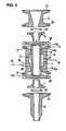
FIG. 1 is a vertical cross-sectional view of a filling channel opening and closing device according to the present invention (with pressurized gas exhausted from chamber); -
FIG. 2 is a cross-sectional exploded view of the filling channel opening and closing device ofFIG. 1 including the filling nozzle; -
FIG. 3 is a vertical cross-sectional view of the filling channel opening and closing device ofFIG. 1 (with pressurized gas supplied in the chamber); -
FIG. 4 is a vertical cross-sectional view of another filling channel opening and closing device according to the present invention; -
FIG. 5 is a vertical cross-sectional view of yet another filling channel opening and closing device according to the present invention; -
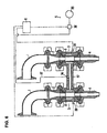
FIG. 6 is a vertical cross-sectional view of still another filling channel opening and closing device according to the present invention; -
FIG. 7 is a vertical cross-sectional view of a different type of filling channel opening and closing device according to the present invention (during introduction of high-pressure pressurized gas into chamber); -
FIG. 8 is a vertical cross-sectional view of the filling channel opening and closing device ofFIG. 7 (during introduction of low-pressure pressurized gas into chamber); -
FIG. 9 is a vertical cross-sectional view of the filling channel opening and closing device ofFIG. 7 (during introduction of pressurized gas at an even lower pressure); and -
FIG. 10 is vertical cross-sectional view of a further different type of filling channel opening and closing device according to the present invention. - The filling channel opening and closing device of the present invention for a liquid product filling apparatus will be described below more specifically with reference to the accompanying drawings including
Figures 1 through 10 . - The liquid product filling apparatus illustrated in
FIG. 1 includes, among others, an elbow duct 1, which is placed in communication with a liquid product storage tank (not shown) with either a filling channel (not shown) in between or nor such filling channel in between; astraight duct 2, which is disposed at the lower end of the elbow duct 1; a filling channel opening andclosing control unit 3, which is disposed at the lower end of thestraight duct 2; afilling nozzle 4, which is disposed at the lower end of the opening andclosing control unit 3; a gas supply and exhaust means 5, which is connected to the opening andclosing control unit 3; a control means 6, which controls the gas supply and exhaust means 5. Accordingly, inFIG. 1 , the filling channel is formed with the elbow duct 1, thestraight duct 2, the filling channel opening andclosing control unit 3, and thefilling nozzle 4. - As shown in
FIGs. 1 and2 , the opening andclosing control unit 3 is comprised of a cylindricalflexible tube 7 formed, for instance, of silicone rubber, achamber 8 in a substantially cylindrical shape and enclosing (the periphery of) theflexible tube 7 therein, and inner pieces 9 and 11 disposed respectively on the inner diameter side of the upper and lower ends of thechamber 8. -
Flanges chamber 8 for joining it to thestraight duct 2 and to the fillingnozzle 4. Retainingsections chamber 8, and a cylindricalcentral recess 16 is formed between theretaining sections 14 and 15 (so as to be in the central portion of the inner periphery of the chamber 8). In addition, as seen fromFIG. 2 , upper andlower recesses 17 and 18 are formed respectively on the inner diameter side (or inside) of theflanges 12 and 13 (so that theupper recess 17 is between the end face 12a of theflange 12 and theretaining section 14, and the lower recess 18 is between theend face 13a of theflange 13 and the retaining section 15). The inner diameter of each one of theretaining sections flexible tube 7, and the inner peripheral surfaces 14a and 15a at both ends of theretaining sections central recess 16 is formed such that its inner diameter is greater than the outer diameter of theflexible tube 7. - The overall configuration of each one of the inner pieces 9 and 11 is substantially frusto-conical and annular, and the outer peripheral surface of each of the inner pieces is concavely curved to an expanded diameter in a shape that substantially follows the inner peripheral surface of each one of the retaining
sections chamber 8. - The assembly of the elbow duct 1,
straight duct 2, opening andclosing control unit 3, and fillingnozzle 4 is made as described below. - The
flange 19, which is formed at the lower end of the elbow duct 1, and theflange 21, which is formed at the upper end of thestraight duct 2, are connected to each other using a clamp 23 with agasket 22 therebetween. - In the opening and
closing control unit 3, theflexible tube 7 is placed in thechamber 8, and the inner pieces 9 and 11 are fitted, head having a smaller diameter first, into both ends of theflexible tube 7. With theflexible tube 7 thus inside thechamber 8 along with the inner pieces 9 and 11, theflange 24, which is formed at the lower end of thestraight duct 2, and theflange 12 of thechamber 8 are connected to each other using aclamp 26, with agasket 25 therebetween; and theflange 13 of thechamber 8 and theflange 27 formed at the upper end of the fillingnozzle 2 are connected to each other using aclamp 29 with agasket 28 therebetween. - In the thus assembled opening and
closing control unit 3, the inner pieces 9 and 11 are respectively fitted into therecesses 17 and 18 at both ends of thechamber 8. The (upper) inner piece 9 and the end face of theflange 24 of thestraight duct 2 press against each other, with an O-ring 31 interposed therebetween. The (lower) inner piece 11 and the end face of theflange 27 of the fillingnozzle 2 also press against each other, with another O-ring 32 sandwiched in between. - In addition, the upper end of the
flexible tube 7 is sandwiched in a compressed state between the retainingsection 14 of thechamber 8 and the inner piece 9, and lower end of thetube 7 is also sandwiched in a compressed state between the retainingsection 15 of thechamber 8 and the inner piece 11. As a result, theflexible tube 7 is held in a predetermined position inside thechamber 8; and at the same time, the entire perimeters of the outer peripheral surfaces of both ends of theflexible tube 7 are closely adhered to the inner peripheral surfaces of the retainingsections chamber 8; and the inner peripheral surfaces of thetube 7 are closely adhered to the outer peripheral surfaces of the inner pieces 9 and 11 throughout the entire perimeter. As a result, leakage of the liquid product between the inner pieces 9 and 11 and theflexible tube 7 is prevented; and in addition, a cylindricalgastight compartment 33 is formed in thechamber 8 so that it is between therecess 16 of thechamber 8 and the outer peripheral surface of theflexible tube 7. In addition, since both ends of theflexible tube 7 are sandwiched respectively between the retainingsections flexible tube 7 is held firmly, and it is less susceptible to misalignment. - For this opening and
closing control unit 3, a gas supply/exhaust port 34 which communicates with thegastight compartment 33 is formed in the side wall of thechamber 8. A gas supply and exhaust means 5, which includes a pressurizedgas supply source 35, achangeover valve 36, aduct 37, etc., is connected to the gas supply/exhaust port 34. Thechangeover valve 36 switches the gas supply/exhaust port 34 to the pressurizedgas supply source 35 side or to the atmosphere for gas release. Furthermore, anopening 38, which communicates with thegastight compartment 33, is formed in the side wall of thechamber 8, and adetection sensor 39, which detects liquid product leakage through theopening 38, is installed in thegastight compartment 33. The operation of thechangeover valve 36 is controlled by the control means 6 throughwiring 30, and the detected signals from thedetection sensor 39 are sent to the control means 6 throughwiring 40. - The filling channel opening and closing device according to the present invention is thus comprised of the opening and
closing control unit 3, the gas supply and exhaust means 5, the control means 6, thedetection sensor 39, etc. - In the liquid product filling apparatus described above, the liquid product stored in the liquid product storage tank (not shown) is forced into the filling channel by an appropriate pressure-applying means, such as, a gravity-based means that utilizes the potential energy of the liquid product inside the tank (as disclosed in the above-described Japanese Patent Nos.
3704270 3454875 straight duct 2, inner piece 9,flexible tube 7, inner piece 11, and fillingnozzle 4, the liquid product exits from the discharge orifice of the fillingnozzle 4 into a container (not shown) which is set underneath the fillingnozzle 4. In addition, the detection of the quantity of the liquid product discharged in a single filling operation can be carried out with a measuring means such as the flow meter described in the Japanese Patent No.3454875 2009-234633 - In the above-described liquid product filling apparatus, one cycle of filling channel opening and closing control of the filling channel opening and closing device of the present invention is carried out as follows:
- By the direction of the control means 6, the
changeover valve 36 places the gas supply/exhaust port 34 in communication with the pressurizedgas supply source 35, so that thegastight compartment 33 in thechamber 8 is pressurized by the pressurized gas supplied from the pressurizedgas supply source 35, and thus, as shown inFIG. 3 , theflexible tube 7 collapses under outside pressure (or by external force which is the pressurized gas), thereby closing the filling channel at theflexible tube portion 7. - When another empty container is moved to under the discharge orifice of the filling
nozzle 4 and held stationary, the control means 6 directs thechangeover valve 36 to switch to the atmosphere for gas release and place the gas supply/exhaust port 34 in communication with the atmosphere for gas release. Thegastight compartment 33 is, as a result, brought to atmospheric pressure and, as shown inFIG. 1 , the restoring force of theflexible tube 7, which is made of an elastic material, as well as the pressure of the liquid product in the filling channel, cause theflexible tube 7 to restore and expand to its original shape, and the filling channel becomes open. As a result, the container (not shown) located underneath the discharge orifice of the fillingnozzle 4 is filled with the liquid product that has passed through theflexible tube 7. - Upon receiving a signal from a flow meter or other dispensed quantity measuring means, the control means 6 issues a changeover command to the
changeover valve 36. Thechangeover valve 36 switches to the pressurizedgas supply source 35 side, and the gas supply/exhaust port 34 is placed in communication with the pressurizedgas supply source 35. Thegastight compartment 33 in thechamber 8 is thus pressurized and, as shown inFIG. 3 , theflexible tube 7 collapses, and the filling channel is closed, thus returning the state of(1) above. In this case, the pressure of the pressurized gas supplied to thechamber 8 from the pressurizedgas supply source 35 is greater than the pressure of the liquid product inside theflexible tube 7. Next, the filled container is moved away from under the discharge orifice of the fillingnozzle 4. - As seen from the above, the above-described filling channel opening and closing device has the following advantages:
- (1) Since the
flexible tube 7 is collapsed by the pressurized gas in a non-contact fashion, the wear of the flexible tube is prevented, making it possible to increase its durability and reduce the frequency of part replacement. Furthermore, the construction of the entire device is simplified, and its cleaning and maintenance properties are improved. - (2) The
flexible tube 7 is held in place (with no tools needed) by simply inserting theflexible tube 7 into thechamber 8 and fitting the inner pieces 9 and 11 into both ends of theflexible tube 7. Accordingly, the attachment and replacement of theflexible tube 7 is carried out easily. - (3) The
detection sensor 39 for detecting liquid product leakage is provided. Thisdetection sensor 39 permits automatic detection of any liquid product leaked into thegastight compartment 33 of thechamber 8 due to, for instance, ruptures in theflexible tube 7. Accordingly, a signal is sent to the control means 6, and the control means 6 stops the operation of the liquid product filling apparatus and/or it notifies the operator by generating an audible alert and/or displaying a warning. -
FIG. 4 illustrates another liquid product filling apparatus including the filling channel opening and closing device according to the present invention. This opening and closing device ofFIG. 4 has a suckback feature. InFIG. 4 , the parts that are substantially identical to the liquid product filling apparatus illustrated inFIG. 1 are assigned the same reference numerals. - The difference of this filling channel opening and closing device illustrated in
FIG. 4 from the device ofFIG. 1 is that two opening andclosing control units straight duct 41 in between. The upstream side opening andclosing control unit 3A is connected to the lower end of thestraight duct 2, and its lower end is connected to the upper end of thestraight duct 41. The downstream side opening andclosing control unit 3B has its upper end connected to the lower end of thestraight duct 41, and its lower end is connected to the upper end of the fillingnozzle 4. The opening andclosing control units - More specifically, the filling channel opening and closing device illustrated in
FIG. 4 is comprised of the opening andclosing control units detection sensors ducts changeover valves closing control units closing control unit 3 illustrated inFIG. 1 . The opening andclosing control unit 3A is comprised of aflexible tube 7A, achamber 8A, andinner pieces 9A and 11A. The opening andclosing control unit 3B is comprised of aflexible tube 7B, achamber 8B, andinner pieces 9B and 11B. Thechangeover valves changeover valve 36 illustrated inFIG. 1 , are respectively connected to the gas supply/exhaust ports chambers Detection sensors detection sensor 39 illustrated inFIG. 1 , are respectively connected to theopenings chambers changeover valves gas supply source 35. The operation of thechangeover valves wirings - One cycle of filling channel opening and closing control of the filling channel opening and closing device illustrated in
FIG. 4 is carried out as follows: - By the direction of the control means 6, the
changeover valve 36A places the gas supply/exhaust port 34A in communication with the pressurizedgas supply source 35 and thechangeover valve 36B places the gas supply/exhaust port 34B in communication with the atmosphere for gas release. As a result, as shown inFIG. 4 , thegastight compartment 33A in thechamber 8A is pressurized, and theflexible tube 7A therein collapses under outside pressure (or by external force), thereby closing the filling channel at theflexible tube portion 7A. On the other hand, thegastight compartment 33B in thechamber 8B is at atmospheric pressure, and theflexible tube 7B is in a restored state, thereby the filling channel is being opened. - When another empty container is moved to under the discharge orifice of the filling
nozzle 4 and held stationary, the control means 6 directs thechangeover valve 36A to switch to the atmosphere, and the gas supply/exhaust port 34A of thechamber 8A is placed in communication with the atmosphere for gas release. Thegastight compartment 33A is, as a result, brought to atmospheric pressure, and the restoring force of theflexible tube 7A, which is made of an elastic material, as well as the pressure of the liquid product in the filling channel, cause theflexible tube 7A to restore and expand, and the filling channel becomes open, and the filling of the container with the liquid product begins. - Upon receiving a signal from a flow meter or other dispensed quantity measuring means, the control means 6 issues a changeover command to the
changeover valves changeover valves gas supply source 35 side and the gas supply/exhaust ports gas supply source 35. Thegastight compartments chambers flexible tubes - Next, the filled container is moved away from under the discharge orifice of the filling
nozzle 4 and, at an appropriate timing before and after thereof, the control means 6 issues a changeover command to thechangeover valve 36B. Since only thechangeover valve 36B is switched to the atmosphere and the gas supply/exhaust port 34B is placed in communication with the atmosphere for gas release, theflexible tube 7B in the downstream side chamber 8b is restored or becomes open under the action of the restoring force of theflexible tube 7B, which is illustrated inFIG. 4 . As a result, the volume of the filling channel in theflexible tube 7B expands, and the portion of the filling channel between theflexible tube 7B and the discharge orifice of the fillingnozzle 4 is placed under negative pressure. As a result, the liquid product at the vicinity of the discharge orifice of the fillingnozzle 4 is sucked back into the filling nozzle 4 (this is called the suckback phenomenon), so that dripping of the liquid product from the discharge orifice of the fillingnozzle 4 when the filling operation ends is prevented. -
FIG. 5 illustrates still another liquid product filling apparatus including the filling channel opening and closing device according to the present invention. InFIG. 5 , the parts that are substantially identical to the liquid product filling apparatus illustrated inFIG. 1 are assigned the same reference numerals. - In this filling channel opening and closing device for a liquid product filling apparatus of
FIG. 5 , the gas supply and exhaust means 5 is comprised of agas supply device 43 and a gas exhaust means 44, and agas supply port 45 and agas exhaust port 46 are formed in thechamber 8. This is the difference of this filling channel opening and closing device illustrated inFIG. 5 from the filling channel opening and closing device ofFIG. 1 . - As seen from
FIG. 5 , thegas supply device 43 is comprised of a pressurizedgas supply source 35, ducts 37 (includingparallel ducts gas supply source 35 and thegas supply port 45, achangeover valve 47 installed in theparallel duct 37a, and achangeover valve 48 and a pressure regulating valve (pressure reducing valve) 49 both installed in theparallel duct 37b. The gas exhaust means 44 is comprised of avacuum pump 51, a duct 52 installed between thevacuum pump 51 and thegas exhaust port 46, and a changeover valve 53 installed in the duct 52. Thechangeover valves gas supply source 35 and thegas supply port 45. The changeover valve 53 establishes and interrupts the communication between thevacuum pump 51 and thegas exhaust port 46. With this construction, thegas supply device 43 can switch between supply of high-pressure pressurized gas and supply of low-pressure pressurized gas. The operation of thechangeover valves respective wirings 54 through 56. - One cycle of filling channel opening and closing control of the filling channel opening and closing device illustrated in
FIG. 5 is carried out as follows: - By the direction of the control means 6, the
changeover valve 47 places thegas supply port 45 in communication with the pressurizedgas supply source 35, thechangeover valve 48 closes the passage of theparallel duct 37b, and the changeover valve 53 closes the passage of the duct 52. As a result, thegastight compartment 33 in thechamber 8 is pressurized, and theflexible tube 7 collapses under outside pressure (or by external force), thereby closing the filling channel at theflexible tube portion 7. - When another empty container is moved to under the discharge orifice of the filling
nozzle 4 and held stationary, the control means 6 directs thechangeover valve 47 to close the passage of theparallel duct 37a and, at the same time, directs the changeover valve 53 to switch to thevacuum pump 51 side. As a result, the pressure inside thegastight compartment 33 is reduced by thevacuum pump 51, theflexible tube 7 is forcedly opened (the reduced pressure inside thegastight compartment 33 assists in the restoring or expansion of the flexible tube 7), and the filling of the container with the liquid product begins. - By the direction of the control means 6, the changeover valve 53 closes the passage of the duct 52 and, at the same time, the
changeover valve 48 switches to the pressurizedgas supply source 35 side. As a result, as shown inFIG. 5 , thegastight compartment 33 is again pressurized, and this time to a relatively low pressure, as a result, theflexible tube 7 is collapsed to a certain extent (as illustrated inFIG. 5 ), the cross-sectional area of the filling channel at theflexible tube portion 7 is decreased, and the velocity and volume of the liquid product flowing through the filling channel are reduced. By way of controlling the velocity and volume of the liquid product flowing through the filling channel in this manner, it is possible to improve the accuracy of filling. - Upon receiving a signal from a flow meter or other dispensed quantity measuring means, the control means 6 issues a changeover command to the
changeover valves changeover valve 47 is switched to the pressurizedgas supply source 35 side, and thechangeover valve 48 closes the passage of theduct 37b. As a result, the supply of pressurized gas from thegas supply device 43 is switched from the low pressure to high pressure, thegastight compartment 33 is re-pressurized to a high pressure, theflexible tube 7 collapses, and the filling channel becomes closed completely. Next, the filled container is moved away from under the discharge orifice of the fillingnozzle 4. -
FIG. 6 illustrates still another liquid product filling apparatus including the filling channel opening and closing device according to the present invention. InFIG. 6 , the parts that are substantially identical to the liquid product filling apparatus illustrated inFIG. 1 are assigned the same reference numerals. - The filling channel opening and closing device for a liquid product filling apparatus of
FIG. 6 is designed to work with a multi-lane (dual-lane) packaging machine that fills multiple containers at once. This liquid product filling apparatus ofFIG. 6 differs from that of the liquid product filling apparatus ofFIG. 1 in that it includes two assemblies provided in parallel, and each assembly includes an elbow duct 1, astraight duct 2, a filling channel opening andclosing control unit 3, and a fillingnozzle 4. The elbow ducts 1 and 1 are provided so as to communication with a shared liquid product storage tank, not shown, either with a filling channel (not shown) in between or without any filling channel in between. - In this filling channel opening and closing device for a liquid product filling apparatus of
FIG. 6 , a shared gas supply and exhaust means 5 is connected to the two opening andclosing control units closing control units chambers conduit 57 interposed therebetween. A gas supply/exhaust port 34 is formed in the connectingconduit 57, and aduct 37, along with a pressurizedgas supply source 35 and achangeover valve 36, is connected to this gas supply/exhaust port 34.Detection sensors 39 are 39 are respectively provided in thechambers closing control units - Though the liquid product filling apparatus has two opening and
closing control units closing control units flexible tubes gas supply source 35 and asingle changeover valve 36, which simplifies the structure of the filling channel opening and closing device. A similar structure can be employed for a type that is designed for three or more lanes of filling channel opening and closing devices. -
FIG. 7 (as well asFIGs. 8 and9 ) illustrates still another liquid product filling apparatus including the filling channel opening and closing device according to the present invention. This liquid product filling apparatus has a suckback feature. InFIG. 7 , the parts that are substantially identical to the liquid product filling apparatus illustrated inFIGs. 1 and5 are assigned the same reference numerals. - In this filling channel opening and closing device for a liquid product filling apparatus of
FIG. 7 (andFIGs. 8 and9 ), the gas supply and exhaust means 5 is comprised of a pressurizedgas supply source 35, ducts 37 (includingparallel ducts gas supply source 35 and a gas supply/exhaust port 58 and agas supply port 59, a pressure regulating valve (pressure reducing valve) 61 installed in theduct 37 on the upstream side of theparallel ducts changeover valve 62 installed in theparallel duct 37a, and achangeover valve 63 and a pressure regulating valve (pressure reducing valve) 64 that are installed in theparallel duct 37b. Theparallel duct 37a is placed in communication with the gas supply/exhaust port 58 while theparallel duct 37b is placed in communication with thegas supply port 59. Thechangeover valve 62 establishes and interrupts the communication between the pressurizedgas supply source 35 and the gas supply/exhaust port 58. In addition, it switches the gas supply/exhaust port 58 to the atmosphere for gas release when closed. Thechangeover valve 63 establishes and interrupts the communication between the pressurizedgas supply source 35 and thegas supply port 59. The operation of thechangeover valves wirings - When the
changeover valve 63 interrupts the communication between the pressurizedgas supply source 35 andgas supply port 59 and thechangeover valve 62 places the pressurizedgas supply source 35 in communication with the gas supply/exhaust port 58, then high-pressure pressurized gas is supplied into thegastight compartment 33 of thechamber 8.FIG. 7 shows theflexible tube 7 collapsed in this situation. As seen fromFIG. 7 , the pressure of the high-pressure pressurized gas supplied into thechamber 8 is set to the level at which a tight contact is produced across a wide (vertical) range of the inner peripheral surface of theflexible tube 7. - When, subsequently, the
changeover valve 62 interrupts the communication between the pressurizedgas supply source 35 and the gas supply/exhaust port 58 and thechangeover valve 63 places the pressurizedgas supply source 35 in communication with thegas supply port 59, then low-pressure pressurized gas is supplied into thegastight compartment 33 of thechamber 8 instead of the high-pressure pressurized gas. Collapsing variations of theflexible tube 7 at such timings (in the two cases) are illustrated inFIGs. 8 and9 . - In the case of
FIG. 8 , the pressure of the low-pressure pressurized gas is set to a level at which theflexible tube 7 remains in a collapsed state (so that the filling channel remains in a closed state). In other words, even though theflexible tube 7 does restore, it restores slightly until a balance is achieved between its own resilience and the force of pressure in thegastight compartment 33, and the tight contact of the inner peripheral surfaces of theflexible tube 7 is maintained (although the area of the contact is smaller compared to that shown inFIG. 7 ). - In the case of
FIG. 9 , the pressure of the low-pressure pressurized gas is set to a level lower than the level in the case ofFIG. 8 ; and at this level theflexible tube 7 is collapsed not completely (so that the filling channel does not remain in a closed state). In other words, the collapsedflexible tube 7 restores until a balance is achieved between its own resilience and the force of pressure in thegastight compartment 33, so that the filling channel is in an open state to some extent. - In either case described above, the volume inside the flexible tube 7 (the filling channel) is increased in comparison with the case in which the high-pressure pressurized gas is supplied into the
gastight compartment 33 which is shown inFIG. 7 . - When the pressure of the low-pressure pressurized gas is set to the level employed in the case of
FIG. 8 , one cycle of filling channel opening and closing control of the filling channel opening and closing device ofFIG. 7 is performed as follows for example: - By the direction of the control means 6, the
changeover valve 63 places thegas supply port 59 in communication with the pressurizedgas supply source 35 and thechangeover valve 62 closes the passage of theparallel duct 37a, thereby pressurizing thegastight compartment 33 in thechamber 8 to a low pressure determined by thepressure regulating valve 64. As shown inFIG. 8 , the pressure inside thegastight compartment 33 maintains theflexible tube 7 in a collapsed state, and the filling channel remains is thus closed. - When another empty container is moved to under the discharge orifice of the filling
nozzle 4 and held stationary, the control means 6 directs thechangeover valve 63 to close the passage of theparallel duct 37b and, at the same time, directs thechangeover valve 62 to switch the gas supply/exhaust port 58 to the atmosphere for gas release (while the pressurizedgas supply source 35 remains closed). As a result, the gas in thegastight compartment 33 is released into the atmosphere and theflexible tube 7 is caused to restore and expand to its original shape (for example, to the state illustrated inFIG. 1 ), and the filling of the container with the liquid product begins at the same time. - At the timing of end of the filling operation (in which the moved container is filled with the liquid product to a predetermined amount), the control means 6 issues a changeover command to the
changeover valve 62, thechangeover valve 62 places the gas supply/exhaust port 58 in communication with the pressurizedgas supply source 35, and thegastight compartment 33 is pressurized to a predetermined high pressure set by thepressure regulating valve 61. As a result, as shown inFIG. 7 , theflexible tube 7 collapses, and the filling channel is closed. - Next, the filled container is moved away from under the discharge orifice of the filling
nozzle 4, and, at an appropriate moment, the control means 6 issues a changeover command to thechangeover valves changeover valve 62 closes the passage of theparallel duct 37a, and thechangeover valve 63 opens theparallel duct 37b and places thegas supply port 59 in communication with the pressurizedgas supply source 35. Accordingly, thegastight compartment 33 in thechamber 8 is switched from a high pressure level to a low pressure level, and thus, as shown inFIG. 8 , theflexible tube 7 restores to expand until a balance is achieved between its own resilience and the force of the pressure in thegastight compartment 33. The collapsed state of theflexible tube 7 and the closed state of the filling channel are maintained. As theflexible tube 7 restores to a certain extent, the volume of the filling channel in theflexible tube 7 expands, and the portion of the filling channel between theflexible tube 7 and the discharge orifice of the fillingnozzle 4 is placed under negative pressure. Liquid product at the vicinity of the discharge orifice of the fillingnozzle 4 is, as a result, sucked back inside the filling nozzle 4 (the suckback phenomenon), and dripping of the liquid product from the discharge orifice when the filling operation ends is prevented. - On the other hand, when the pressure of the low-pressure pressurized gas in the filling channel opening and closing device illustrated in
FIG. 7 is set to the level used in the case ofFIG. 9 , the filling channel in theflexible tube 7 remains open to some extent in the "Before Filling" step described in (1) above. In addition, when thegastight compartment 33 is switched from a high pressure level to a low pressure level during the suckback operation described in (4) above, theflexible tube 7 restores to expand until such a state is reached that the filling channel remains open to some extent. In this case as well, as theflexible tube 7 restores, the volume of the filling channel in theflexible tube 7 expands, and the portion of the filling channel between theflexible tube 7 and the discharge orifice of the fillingnozzle 4 is placed under negative pressure. Liquid product near the discharge orifice of the fillingnozzle 4 is, as a result, sucked back inside the filling nozzle 4 (the suckback phenomenon), so that dripping of the liquid product from the discharge orifice when the filling operation ends is prevented. - In the filling channel opening and closing device illustrated in
FIG. 7 , the expansion of the volume of the filling channel that accompanies the restoring of theflexible tube 7 in the case ofFIG. 9 is greater than in the case ofFIG. 8 , and this is advantageous because the suction force of the suckback is correspondingly stronger. However, since the filling channel in the opening andclosing control unit 3 stays open during the suckback operation, the operation ofFIG. 9 is used only when no pressure force is applied from the upstream side at the end of the filling operation. - For example, if the filling channel opening and closing device illustrated in
FIG. 7 is used in a filling apparatus that uses a measuring pump including a metering cylinder and a piston (as disclosed in, for example, Japanese Patent Application Laid-Open (Kokai) No.H04-201801 H07-2479 closing control unit 3. Accordingly, the filling channel opening and closing device ofFIG. 7 is able to perform suckback in this filling apparatus. - On the other hand, when it is used in a flow meter-type apparatus or another pressurized filling apparatus in which the pressure of the liquid is constantly applied to the filling channel by a liquid storage tank (as disclosed in, for instance, Japanese Patent Nos.
3704270 3454875 2008-94496 2009-234633 closing control unit 3 to prevent application of the upstream side pressure to the filling channel of the opening andclosing control unit 3 at the moment when the filling operation ends. Accordingly, for such a flow meter-type apparatus or another pressurized filling apparatus. the filling channel opening and closing device according to the present invention shown in, for example,FIG. 4 or a filling channel opening and closing device of another type can be installed as the upstream filling channel opening and closing device. - In the filling channel opening and closing device shown in
FIG. 7 , a force of pressure is being applied to thegastight compartment 33 of thechamber 8 during suckback. Accordingly, in comparison with theflexible tube 7B used in the filling channel opening and closing device ofFIG. 4 , the degree to which theflexible tube 7 restores during suckback is lower, the increase in the volume of the filling channel in theflexible tube 7 is smaller, and the suckback action (suckback force) is weaker. Accordingly, the filling channel opening and closing device ofFIG. 7 is suitable for cases in which the diameters of the fillingnozzle 4 andflexible tube 7 are relatively small (and the dispensed amount is relatively small) or for cases in which the viscosity of the liquid product that the containers are filled with is relatively low. - Furthermore, in the filling channel opening and closing device of
FIG. 7 , theparallel duct 37a andparallel duct 37b can be both connected to the gas supply/exhaust port 58 as shown inFIG. 5 . In this case, thegas supply port 59 becomes unnecessary. In addition, the functions of thechangeover valve 62 andchangeover valve 63 can be switched. In this case, accordingly, thegas supply port 59 acts as a gas supply/exhaust port, and the gas supply/exhaust port 58 acts as a gas supply port. In other words, thechangeover valve 63 serves to establish and interrupt the communication between the pressurizedgas supply source 35 and thegas supply port 59 and, in addition, to switch thegas supply port 59 to the atmosphere for gas release when closed; and on the other hand, thechangeover valve 62 serves to establish and interrupt the communication between the pressurizedgas supply source 35 and the gas supply/exhaust port 58; and the release of gas from thegastight compartment 33 into the atmosphere is effected on theparallel duct 37b side. -
FIG. 10 illustrates another liquid product filling apparatus including the filling channel opening and closing device according to the present invention. This liquid product filling apparatus has a feature to detect the presence of leaks (liquid leakage) in theflexible tube 7. InFIG. 10 , the parts that are substantially identical to the liquid product filling apparatus illustrated inFIG. 1 are assigned the same reference numerals. - In this filling channel opening and closing device for a liquid product filling apparatus, the gas supply and exhaust means 5 is comprised of a pressurized
gas supply source 35, a pressure regulating valve (pressure reducing valve) 65, achangeover valve 36, agas flow meter 66, aduct 37, etc. Thegas flow meter 66 is installed in theduct 37 between thechangeover valve 36 and gas supply/exhaust port 34. Thechangeover valve 36 switches the gas supply/exhaust port 34 to the pressurizedgas supply source 35 side or to the atmosphere for gas release side. - In this liquid product filling apparatus, one cycle of filling channel opening and closing control of the filling channel opening and closing device is carried out as in the same manner as that of the liquid product filling apparatus of
FIG. 1 . - The
gas flow meter 66 measures the flow rate of the pressurized gas in theduct 37 at least when the gas supply/exhaust port 34 and pressurizedgas supply source 35 are in communication (when the pressurized gas is supplied into the gastight compartment 33) during the above-described single cycle, and it sends out a measurement signal to the control means 6. - After the
flexible tube 7 is collapsed by the pressurized gas, if there are no ruptures or pinholes in theflexible tube 7, then no pressurized gas flow is generated (its flow is stopped) in theduct 37. In such a case, the control means 6 determines that there are no leaks (or no liquid product leakage). - On the other hand, if ruptures or pinholes are formed in the
flexible tube 7, then, due to the fact that the pressure of the pressurized gas is higher than the liquid pressure in theflexible tube 7, the gas in thegastight compartment 33 in thechamber 8 penetrates inside theflexible tube 7 and, as a result, a pressurized gas flow is generated inside theduct 37 even after the collapse of theflexible tube 7, and thegas flow meter 66 measures this pressurized gas flow. In this case, the control means 6 determines that there is a leak (liquid product leakage). - As seen from the above, the filling channel opening and closing device is capable of automatic early detection and identification of liquid product leakage due to ruptures or pinholes (or any damage for any reason) in the
flexible tube 7, and it stops the operation of the liquid product filling apparatus and/or notifies the operator by generating an audible alert and/or displaying a warning. - The filling channel opening and closing device according to the present invention is not limited to the above-described examples and allows various modifications as described below:
- (1) In the above-described examples, the opening and
closing control unit 3 is provided directly on the upstream side of the fillingnozzle 4. However, it can be installed anywhere as long as it is located within the filling channel between the liquid product storage tank and the discharge orifice of the fillingnozzle 4. Nonetheless, it is preferably located in the vicinity of the discharge orifice of the fillingnozzle 4 as shown inFIGs. 1 to 10 . When two opening andclosing control units FIG. 5 , it is preferable to provide at least the downstream side opening andclosing control unit 3B in the vicinity of the fillingnozzle 4. - (2) In the examples described above, the
detection sensor 39 for detecting liquid product leakage is provided in thechamber 8 of the opening andclosing control unit 3. However, instead of thedetection sensor 39, it is possible to use achamber 8 that is made of a transparent material, such as acrylic resin, etc., so that the contents of the gastight compartment are visible to allow visual inspection and recognition of liquid product leakage. Fabricating thechamber 8 from a transparent material has the advantage that the operation of thechangeover valve 36, etc. can be checked for malfunctions by visually observing the collapse and restoring of theflexible tube 7. It is also possible to provide adetection sensor 39 in addition to use of thetransparent chamber 8. - (3) In the structure of
FIG. 6 , twochambers 8 are integrated into one body by the connectingconduit 57. However, twochambers 8 can be provided independently without using the connectingconduit 57. In this structure, a gas supply/exhaust port is formed in eachchamber 8, ducts subsequent to thechangeover valve 36 is provided in parallel (divided in two), and each one of them is connected to the gas supply/exhaust port. This structure is able to make the same action as that ofFIG. 6 .
Claims (11)
- A filling channel opening and closing device for a liquid product filling apparatus, said device including a flexible tube installed as part of a filling channel which is provided between a liquid product storage tank and a discharge orifice of a filling nozzle, said opening and closing device closing and opening the filling channel by collapsing and restoring the flexible tube with an external force, said opening and closing device comprising:a filling channel opening and closing control unit that includes said flexible tube and a chamber which encloses a periphery of said flexible tube in a gastight manner;a gas supply and exhaust means that is connected to said opening and closing control unit and collapses and restores said flexible tube by supplying pressurized gas into said chamber and exhausting the gas from said chamber; anda control means that controls said gas supply and exhaust means to supply and exhaust gas in and out of the chamber at a predetermined timing.
- The filling channel opening and closing device for a liquid product filling apparatus according to claim 1, wherein
said chamber is substantially cylindrical in shape,
a cylindrical gastight compartment is formed between the outer peripheral surface of said flexible tube and the inner surface of said chamber, and
the pressurized gas is supplied into said gastight compartment and exhausted from said gastight compartment. - The filling channel opening and closing device for a liquid product filling apparatus according to claim 2, wherein
said chamber is provided with retaining sections that tightly adhere to an entire perimeter of an outer peripheral surface of both ends of said flexible tube at front and back of the gastight compartment,
hollow inner pieces that form part of the filling channel are disposed inside of the retaining sections, said inner pieces being fitted into both ends of said flexible tube and tightly adhere to an entire perimeter of the inner peripheral surface of said flexible tube, and
both ends of said flexible tube are respectively sandwiched between the retaining sections of said chamber and said inner pieces and are held in predetermined positions. - The filling channel opening and closing device for a liquid product filling apparatus according to any one of claims 1 to 3, wherein
two of said opening and closing control units are provided in series in said filling channel,
said gas supply and exhaust means is connected to each one of said two opening and closing control units, and
after supplying the pressurized gas into chambers of said two opening and closing control units at an end of a filling operation, the gas is exhausted from a chamber of said opening and closing control unit of downstream side at a predetermined timing. - The filling channel opening and closing device for a liquid product filling apparatus according to any of one claims 1 to 3, wherein
said gas supply and exhaust means switches a pressure of the pressurized gas supplied into said chamber in two levels comprising a first pressure level that closes said filling channel by collapsing said flexible tube and a second pressure level that is lower in pressure than the first pressure level, and
after supplying the pressurized gas into said chamber at the first pressure level at the end of the filling operation, said gas supply and exhaust means switches over to the second pressure level at a predetermined timing. - The filling channel opening and closing device according to claim 5, wherein
a pressure level of the pressurized gas of second pressure level is set to a level at which said flexible tube is collapsed and said filling channel is maintained in a closed state. - The filling channel opening and closing device according to claim 5, wherein a pressure level of the pressurized gas of second pressure level is set to a level at which said flexible tube is incompletely collapsed.
- The filling channel opening and closing device for a liquid product filling apparatus according to any one of claims 1 to 7, further comprising a gas flow meter installed, as part of said gas supply and exhaust means, in a pressurized gas supply duct provided in communication with said chamber, said flow meter measuring a flow rate of the pressurized gas while the pressurized gas is being supplied into said chamber, and said control means, with a use of measurements from said flow meter, making a determination as to a presence of leak of the pressurized gas.
- The filling channel opening and closing device for a liquid product filling apparatus according to any one of claims 1 to 8, wherein said chamber is made of a transparent material.
- The filling channel opening and closing device for a liquid product filling apparatus according to any one of claims 1 to 9, further comprising a detection sensor installed in said chamber for detecting leakage of the liquid product.
- The filling channel opening and closing device for a liquid product filling apparatus according to any one of claims 1 to 3, wherein a pressure of the pressurized gas supplied to said chamber is greater than a pressure of the liquid product.
Applications Claiming Priority (2)
| Application Number | Priority Date | Filing Date | Title |
|---|---|---|---|
| JP2010019984 | 2010-02-01 | ||
| JP2010101277A JP5439269B2 (en) | 2010-02-01 | 2010-04-26 | Filling passage opening and closing device for liquid filling machine |
Publications (3)
| Publication Number | Publication Date |
|---|---|
| EP2354082A2 true EP2354082A2 (en) | 2011-08-10 |
| EP2354082A3 EP2354082A3 (en) | 2013-05-29 |
| EP2354082B1 EP2354082B1 (en) | 2014-07-02 |
Family
ID=44064197
Family Applications (1)
| Application Number | Title | Priority Date | Filing Date |
|---|---|---|---|
| EP11000730.9A Not-in-force EP2354082B1 (en) | 2010-02-01 | 2011-01-31 | Filling channel opening and closing device for liquid product filling apparatus |
Country Status (6)
| Country | Link |
|---|---|
| US (1) | US8740175B2 (en) |
| EP (1) | EP2354082B1 (en) |
| JP (1) | JP5439269B2 (en) |
| KR (1) | KR101712863B1 (en) |
| CN (1) | CN102190090B (en) |
| ES (1) | ES2478944T3 (en) |
Cited By (5)
| Publication number | Priority date | Publication date | Assignee | Title |
|---|---|---|---|---|
| FR2992305A1 (en) * | 2012-06-26 | 2013-12-27 | Gangloff Scoma | DEVICE FOR FILLING BOTTLES OF WINE |
| EP2708491A1 (en) * | 2012-09-12 | 2014-03-19 | Krones AG | Device and method for filling a container with a filling product |
| DE102015219273A1 (en) * | 2015-10-06 | 2017-04-06 | Festo Ag & Co. Kg | diaphragm means |
| WO2017062696A1 (en) * | 2015-10-08 | 2017-04-13 | The Procter & Gamble Company | Low splash fluid shutoff valve assembly |
| EP3495292B1 (en) | 2014-05-15 | 2020-10-07 | Nordson Corporation | Dense phase pump diagnostics |
Families Citing this family (19)
| Publication number | Priority date | Publication date | Assignee | Title |
|---|---|---|---|---|
| BR112013010366B1 (en) * | 2010-10-29 | 2020-12-08 | Shell Internationale Research Maatschappij B.V. | collapsible coating device, and method for controlling flow |
| US20150247580A1 (en) * | 2014-02-28 | 2015-09-03 | University Of Washington Through Its Center For Commercialization | Assembly-Free Additively-Manufactured Fluidic Control Elements |
| US20150267822A1 (en) * | 2014-03-18 | 2015-09-24 | Mine Support Products (Pty) Ltd | Valve |
| CN104295761A (en) * | 2014-09-25 | 2015-01-21 | 广州达意隆包装机械股份有限公司 | Plunger valve |
| JP2016084719A (en) * | 2014-10-23 | 2016-05-19 | 東京エレクトロン株式会社 | Liquid feeding method, liquid feeding system, and computer readable recording medium |
| US10174849B2 (en) * | 2014-12-18 | 2019-01-08 | Festo Corporation | Multiple stage pinch valve and filling apparatus using a multiple stage pinch valve |
| WO2017087638A1 (en) | 2015-11-20 | 2017-05-26 | Massachusetts Institute Of Technology | Low-pressure and low-energy self-regulating valve |
| WO2017134654A1 (en) * | 2016-02-04 | 2017-08-10 | Egmo Ltd. | Pinch valve |
| CN105864452A (en) * | 2016-06-15 | 2016-08-17 | 四川森洁燃气设备有限公司 | Relieving injection rail |
| KR102273468B1 (en) * | 2017-03-10 | 2021-07-07 | 현대자동차주식회사 | Variable compressor |
| DE102017206533A1 (en) * | 2017-04-18 | 2018-10-18 | Festo Ag & Co. Kg | Pinch valve and method for operating a pinch valve |
| EP3679279A1 (en) | 2017-09-08 | 2020-07-15 | The Procter and Gamble Company | Side shutoff piston valve assembly |
| DE102017124397A1 (en) * | 2017-10-19 | 2019-04-25 | Khs Gmbh | Device and method for aseptic pressure relief |
| CN109987283B (en) * | 2017-12-29 | 2022-03-15 | 内蒙古蒙牛乳业(集团)股份有限公司 | Discharging device |
| EP3755227A4 (en) * | 2018-02-22 | 2022-02-16 | SRS Medical Systems, LLC | Urodynamic investigation apparatus, system, & methods |
| DE102018108760A1 (en) | 2018-04-12 | 2019-10-17 | Khs Corpoplast Gmbh | Method and device for filling containers with carbonated filling material and the subsequent closing of the filled containers |
| US10850964B2 (en) * | 2019-03-22 | 2020-12-01 | Accenture Global Solutions Limited | System and method for filling containers with a precise amount of fluid |
| FR3104550B1 (en) * | 2019-12-16 | 2022-01-07 | Serac Group | Filling station for packaging installation comprising a filling spout with integrated suction channel |
| JP7237225B1 (en) | 2021-10-28 | 2023-03-10 | 岩井ファルマテック株式会社 | Filling needle module and filling device |
Citations (6)
| Publication number | Priority date | Publication date | Assignee | Title |
|---|---|---|---|---|
| JPH04201801A (en) | 1990-11-30 | 1992-07-22 | Dainippon Printing Co Ltd | Device for loading liquid containing solid |
| JPH072479A (en) | 1993-06-15 | 1995-01-06 | Mitsubishi Electric Corp | Escalator with footstep for wheelchair |
| JP3454875B2 (en) | 1993-08-11 | 2003-10-06 | 澁谷工業株式会社 | Liquid filling machine |
| JP3704270B2 (en) | 2000-02-16 | 2005-10-12 | 靜甲株式会社 | Filling device for fluid filling machine |
| JP2008094496A (en) | 2006-09-15 | 2008-04-24 | Naomi:Kk | Filling machine |
| JP2009234633A (en) | 2008-03-27 | 2009-10-15 | Q P Corp | Liquid filling machine |
Family Cites Families (27)
| Publication number | Priority date | Publication date | Assignee | Title |
|---|---|---|---|---|
| US2590215A (en) * | 1947-02-21 | 1952-03-25 | Frank C Sausa | Variable throat restricter valve |
| US2884963A (en) * | 1956-04-27 | 1959-05-05 | Prec Metalsmiths Inc | Investing apparatus |
| US3143124A (en) * | 1960-12-19 | 1964-08-04 | Shell Oil Co | Aiding flow of pseudo-plastics through conduits |
| US3561723A (en) * | 1968-05-07 | 1971-02-09 | Edward T Cugini | Stripping and blow-out preventer device |
| JPS5462530A (en) * | 1977-10-27 | 1979-05-19 | Shimizu Construction Co Ltd | Valve device |
| DE2812441C2 (en) * | 1977-03-25 | 1984-12-13 | The Shimizu Construction Co. Ltd., Tokio/Tokyo | Funnel pipe for underwater concreting |
| US4403764A (en) * | 1981-10-08 | 1983-09-13 | Otto Engineering, Inc. | Method and apparatus for controlling flow of work materials |
| DE3789268T2 (en) * | 1986-10-20 | 1994-06-16 | Matsushita Electric Ind Co Ltd | Device for interrupting a gas flow. |
| JPH0617747B2 (en) * | 1986-10-20 | 1994-03-09 | 松下電器産業株式会社 | Gas shutoff device |
| US4967940A (en) * | 1989-02-21 | 1990-11-06 | Minnesota Mining And Manufacturing Co. | Method and apparatus for precision squeeze tube valving, pumping and dispensing of work fluid(s) |
| US5107883A (en) * | 1990-03-02 | 1992-04-28 | Bauer Industries, Inc. | Pinch valve control system for water line isolation and method |
| US5161773A (en) * | 1990-08-01 | 1992-11-10 | Numed, Inc. | Method and apparatus for controlling fluid flow |
| FR2667391A1 (en) * | 1990-09-28 | 1992-04-03 | Guyot Jean | Device for volumetric metering of at least one product and for filling containers |
| US5797415A (en) * | 1993-10-15 | 1998-08-25 | Horizon Resources Corp. | Insulating jacket for hot and cold piping systems and the method of use |
| DE4344497A1 (en) * | 1993-12-24 | 1995-06-29 | Mewes Gmbh | Filling machine for dispensing of fluid materials |
| JPH07315302A (en) * | 1994-05-20 | 1995-12-05 | Daido Steel Co Ltd | Apparatus for filling measured quantity of powder and valve used therefor |
| US5549793A (en) * | 1994-08-02 | 1996-08-27 | Abb Industrial Systems, Inc. | Control of dilution lines in a dilution headbox of a paper making machine |
| FR2739431B1 (en) * | 1995-09-28 | 1997-12-12 | Cazas Ets | PNEUMATIC MEMBRANE VALVE |
| DE19615472A1 (en) * | 1996-04-19 | 1997-10-23 | Frank Kampfmann | Safety function element for a line |
| US5799227A (en) * | 1996-06-06 | 1998-08-25 | Moore Business Forms, Inc. | Non-magnetic toner dynamic recycling |
| JP4066062B2 (en) * | 2000-05-18 | 2008-03-26 | 株式会社 ワイ・エム・エス | Method and apparatus for pneumatic transport of powder |
| JP2002255284A (en) * | 2001-03-06 | 2002-09-11 | Tsukishima Kikai Co Ltd | Liquid filling valve and method for filling liquid |
| US6572259B2 (en) * | 2001-04-20 | 2003-06-03 | Burnett Lime Co., Inc. | Apparatus and method to dispense a slurry |
| JP2004195381A (en) * | 2002-12-19 | 2004-07-15 | Toray Ind Inc | Liquid separating apparatus and method for operating liquid separation membrane module |
| JP4530955B2 (en) * | 2005-09-08 | 2010-08-25 | エバラ食品工業株式会社 | Liquid filling device |
| DE102006045987A1 (en) * | 2006-09-27 | 2008-04-03 | Khs Ag | Method for filling containers with a liquid product and filling system |
| WO2011067794A1 (en) * | 2009-12-01 | 2011-06-09 | Sidel S.P.A. Con Socio Unico | Flow regulator, in particular for filling machines, and filling machine comprising such a flow regulator |
-
2010
- 2010-04-26 JP JP2010101277A patent/JP5439269B2/en not_active Expired - Fee Related
- 2010-12-03 KR KR1020100122669A patent/KR101712863B1/en active IP Right Grant
-
2011
- 2011-01-26 CN CN201110037494.7A patent/CN102190090B/en not_active Expired - Fee Related
- 2011-01-31 ES ES11000730.9T patent/ES2478944T3/en active Active
- 2011-01-31 US US13/018,048 patent/US8740175B2/en not_active Expired - Fee Related
- 2011-01-31 EP EP11000730.9A patent/EP2354082B1/en not_active Not-in-force
Patent Citations (6)
| Publication number | Priority date | Publication date | Assignee | Title |
|---|---|---|---|---|
| JPH04201801A (en) | 1990-11-30 | 1992-07-22 | Dainippon Printing Co Ltd | Device for loading liquid containing solid |
| JPH072479A (en) | 1993-06-15 | 1995-01-06 | Mitsubishi Electric Corp | Escalator with footstep for wheelchair |
| JP3454875B2 (en) | 1993-08-11 | 2003-10-06 | 澁谷工業株式会社 | Liquid filling machine |
| JP3704270B2 (en) | 2000-02-16 | 2005-10-12 | 靜甲株式会社 | Filling device for fluid filling machine |
| JP2008094496A (en) | 2006-09-15 | 2008-04-24 | Naomi:Kk | Filling machine |
| JP2009234633A (en) | 2008-03-27 | 2009-10-15 | Q P Corp | Liquid filling machine |
Cited By (7)
| Publication number | Priority date | Publication date | Assignee | Title |
|---|---|---|---|---|
| FR2992305A1 (en) * | 2012-06-26 | 2013-12-27 | Gangloff Scoma | DEVICE FOR FILLING BOTTLES OF WINE |
| EP2679535A3 (en) * | 2012-06-26 | 2014-03-19 | Gangloff Scoma | Device for filling a bottle of at least one type with a beverage |
| EP2708491A1 (en) * | 2012-09-12 | 2014-03-19 | Krones AG | Device and method for filling a container with a filling product |
| EP3495292B1 (en) | 2014-05-15 | 2020-10-07 | Nordson Corporation | Dense phase pump diagnostics |
| DE102015219273A1 (en) * | 2015-10-06 | 2017-04-06 | Festo Ag & Co. Kg | diaphragm means |
| WO2017062696A1 (en) * | 2015-10-08 | 2017-04-13 | The Procter & Gamble Company | Low splash fluid shutoff valve assembly |
| CN108137303A (en) * | 2015-10-08 | 2018-06-08 | 宝洁公司 | Low spatter fluid shut-off valve |
Also Published As
| Publication number | Publication date |
|---|---|
| CN102190090B (en) | 2014-09-03 |
| KR20110089809A (en) | 2011-08-09 |
| ES2478944T3 (en) | 2014-07-23 |
| CN102190090A (en) | 2011-09-21 |
| EP2354082A3 (en) | 2013-05-29 |
| US20110186757A1 (en) | 2011-08-04 |
| KR101712863B1 (en) | 2017-03-07 |
| EP2354082B1 (en) | 2014-07-02 |
| JP5439269B2 (en) | 2014-03-12 |
| US8740175B2 (en) | 2014-06-03 |
| JP2011173648A (en) | 2011-09-08 |
Similar Documents
| Publication | Publication Date | Title |
|---|---|---|
| EP2354082B1 (en) | Filling channel opening and closing device for liquid product filling apparatus | |
| US10974954B2 (en) | Emptying device for viscous materials and method for same | |
| US2665825A (en) | Pressure-operable liquid dispensing apparatus | |
| US6817386B2 (en) | Filling valve | |
| KR100754342B1 (en) | Method and apparatus for dispensing fluids | |
| US4111613A (en) | Bladder actuated pumping system | |
| CA2716003A1 (en) | Disposable pump with suck-back mechanism | |
| WO2014126751A2 (en) | Metered dose squeeze dispenser | |
| CN105605371A (en) | Building pipeline overhauling device | |
| US20190345925A1 (en) | Diaphragm Pump Device And Diaphragm Pump Having A Diaphragm Pump Device And An Actuation Device | |
| KR20100106613A (en) | Method for filling and evacuating a dispenser unit and filling insert for dispenser unit | |
| WO2008093172A8 (en) | Metering device for dispensing a dose of pressurized fluid | |
| US3937440A (en) | Metering pump and combination two-section pinch-off aspirator valve | |
| US20190353159A1 (en) | Operating Device, Method For Operating An Operating Device, Diaphragm Pump Having An Operating Device And A Diaphragm Pump Device, And A Blood Treatment Apparatus Having A Diaphragm Pump | |
| US4254804A (en) | Filling device for filling containers | |
| JP3540428B2 (en) | Liquid filling method and device | |
| US4243160A (en) | Device for filling a measured quantity of a flowing medium into a package | |
| EP2949618A1 (en) | Method and device for contact filling an article with pourable product | |
| JPH07125799A (en) | Method and device for pouring out liquid in bag-in-box | |
| US3757832A (en) | Pressure-fill container filling machine | |
| US5842611A (en) | Dispensing device | |
| CN109931425B (en) | Leak protection emptying devices | |
| CN108344452A (en) | A kind of detection device detecting packaging bag air-tightness and resistance to pressure | |
| CA1057714A (en) | Antidrip volumetric rapid filling machine | |
| WO2020196057A1 (en) | Dispenser |
Legal Events
| Date | Code | Title | Description |
|---|---|---|---|
| PUAI | Public reference made under article 153(3) epc to a published international application that has entered the european phase |
Free format text: ORIGINAL CODE: 0009012 |
|
| AK | Designated contracting states |
Kind code of ref document: A2 Designated state(s): AL AT BE BG CH CY CZ DE DK EE ES FI FR GB GR HR HU IE IS IT LI LT LU LV MC MK MT NL NO PL PT RO RS SE SI SK SM TR |
|
| AX | Request for extension of the european patent |
Extension state: BA ME |
|
| PUAL | Search report despatched |
Free format text: ORIGINAL CODE: 0009013 |
|
| AK | Designated contracting states |
Kind code of ref document: A3 Designated state(s): AL AT BE BG CH CY CZ DE DK EE ES FI FR GB GR HR HU IE IS IT LI LT LU LV MC MK MT NL NO PL PT RO RS SE SI SK SM TR |
|
| AX | Request for extension of the european patent |
Extension state: BA ME |
|
| RIC1 | Information provided on ipc code assigned before grant |
Ipc: B67C 3/28 20060101AFI20130425BHEP Ipc: B67C 3/26 20060101ALI20130425BHEP |
|
| 17P | Request for examination filed |
Effective date: 20131128 |
|
| RBV | Designated contracting states (corrected) |
Designated state(s): AL AT BE BG CH CY CZ DE DK EE ES FI FR GB GR HR HU IE IS IT LI LT LU LV MC MK MT NL NO PL PT RO RS SE SI SK SM TR |
|
| GRAP | Despatch of communication of intention to grant a patent |
Free format text: ORIGINAL CODE: EPIDOSNIGR1 |
|
| INTG | Intention to grant announced |
Effective date: 20140129 |
|
| GRAS | Grant fee paid |
Free format text: ORIGINAL CODE: EPIDOSNIGR3 |
|
| GRAA | (expected) grant |
Free format text: ORIGINAL CODE: 0009210 |
|
| AK | Designated contracting states |
Kind code of ref document: B1 Designated state(s): AL AT BE BG CH CY CZ DE DK EE ES FI FR GB GR HR HU IE IS IT LI LT LU LV MC MK MT NL NO PL PT RO RS SE SI SK SM TR |
|
| REG | Reference to a national code |
Ref country code: GB Ref legal event code: FG4D |
|
| REG | Reference to a national code |
Ref country code: CH Ref legal event code: EP Ref country code: AT Ref legal event code: REF Ref document number: 675821 Country of ref document: AT Kind code of ref document: T Effective date: 20140715 |
|
| REG | Reference to a national code |
Ref country code: ES Ref legal event code: FG2A Ref document number: 2478944 Country of ref document: ES Kind code of ref document: T3 Effective date: 20140723 |
|
| REG | Reference to a national code |
Ref country code: IE Ref legal event code: FG4D |
|
| REG | Reference to a national code |
Ref country code: DE Ref legal event code: R096 Ref document number: 602011008037 Country of ref document: DE Effective date: 20140814 |
|
| REG | Reference to a national code |
Ref country code: AT Ref legal event code: MK05 Ref document number: 675821 Country of ref document: AT Kind code of ref document: T Effective date: 20140702 |
|
| REG | Reference to a national code |
Ref country code: NL Ref legal event code: VDEP Effective date: 20140702 |
|
| REG | Reference to a national code |
Ref country code: LT Ref legal event code: MG4D |
|
| PG25 | Lapsed in a contracting state [announced via postgrant information from national office to epo] |
Ref country code: LT Free format text: LAPSE BECAUSE OF FAILURE TO SUBMIT A TRANSLATION OF THE DESCRIPTION OR TO PAY THE FEE WITHIN THE PRESCRIBED TIME-LIMIT Effective date: 20140702 Ref country code: PT Free format text: LAPSE BECAUSE OF FAILURE TO SUBMIT A TRANSLATION OF THE DESCRIPTION OR TO PAY THE FEE WITHIN THE PRESCRIBED TIME-LIMIT Effective date: 20141103 Ref country code: GR Free format text: LAPSE BECAUSE OF FAILURE TO SUBMIT A TRANSLATION OF THE DESCRIPTION OR TO PAY THE FEE WITHIN THE PRESCRIBED TIME-LIMIT Effective date: 20141003 Ref country code: CZ Free format text: LAPSE BECAUSE OF FAILURE TO SUBMIT A TRANSLATION OF THE DESCRIPTION OR TO PAY THE FEE WITHIN THE PRESCRIBED TIME-LIMIT Effective date: 20140702 Ref country code: NO Free format text: LAPSE BECAUSE OF FAILURE TO SUBMIT A TRANSLATION OF THE DESCRIPTION OR TO PAY THE FEE WITHIN THE PRESCRIBED TIME-LIMIT Effective date: 20141002 Ref country code: BG Free format text: LAPSE BECAUSE OF FAILURE TO SUBMIT A TRANSLATION OF THE DESCRIPTION OR TO PAY THE FEE WITHIN THE PRESCRIBED TIME-LIMIT Effective date: 20141002 Ref country code: SE Free format text: LAPSE BECAUSE OF FAILURE TO SUBMIT A TRANSLATION OF THE DESCRIPTION OR TO PAY THE FEE WITHIN THE PRESCRIBED TIME-LIMIT Effective date: 20140702 Ref country code: FI Free format text: LAPSE BECAUSE OF FAILURE TO SUBMIT A TRANSLATION OF THE DESCRIPTION OR TO PAY THE FEE WITHIN THE PRESCRIBED TIME-LIMIT Effective date: 20140702 |
|
| PG25 | Lapsed in a contracting state [announced via postgrant information from national office to epo] |
Ref country code: PL Free format text: LAPSE BECAUSE OF FAILURE TO SUBMIT A TRANSLATION OF THE DESCRIPTION OR TO PAY THE FEE WITHIN THE PRESCRIBED TIME-LIMIT Effective date: 20140702 Ref country code: NL Free format text: LAPSE BECAUSE OF FAILURE TO SUBMIT A TRANSLATION OF THE DESCRIPTION OR TO PAY THE FEE WITHIN THE PRESCRIBED TIME-LIMIT Effective date: 20140702 Ref country code: RS Free format text: LAPSE BECAUSE OF FAILURE TO SUBMIT A TRANSLATION OF THE DESCRIPTION OR TO PAY THE FEE WITHIN THE PRESCRIBED TIME-LIMIT Effective date: 20140702 Ref country code: AT Free format text: LAPSE BECAUSE OF FAILURE TO SUBMIT A TRANSLATION OF THE DESCRIPTION OR TO PAY THE FEE WITHIN THE PRESCRIBED TIME-LIMIT Effective date: 20140702 Ref country code: IS Free format text: LAPSE BECAUSE OF FAILURE TO SUBMIT A TRANSLATION OF THE DESCRIPTION OR TO PAY THE FEE WITHIN THE PRESCRIBED TIME-LIMIT Effective date: 20141102 Ref country code: CY Free format text: LAPSE BECAUSE OF FAILURE TO SUBMIT A TRANSLATION OF THE DESCRIPTION OR TO PAY THE FEE WITHIN THE PRESCRIBED TIME-LIMIT Effective date: 20140702 Ref country code: LV Free format text: LAPSE BECAUSE OF FAILURE TO SUBMIT A TRANSLATION OF THE DESCRIPTION OR TO PAY THE FEE WITHIN THE PRESCRIBED TIME-LIMIT Effective date: 20140702 Ref country code: HR Free format text: LAPSE BECAUSE OF FAILURE TO SUBMIT A TRANSLATION OF THE DESCRIPTION OR TO PAY THE FEE WITHIN THE PRESCRIBED TIME-LIMIT Effective date: 20140702 |
|
| REG | Reference to a national code |
Ref country code: DE Ref legal event code: R097 Ref document number: 602011008037 Country of ref document: DE |
|
| PG25 | Lapsed in a contracting state [announced via postgrant information from national office to epo] |
Ref country code: DK Free format text: LAPSE BECAUSE OF FAILURE TO SUBMIT A TRANSLATION OF THE DESCRIPTION OR TO PAY THE FEE WITHIN THE PRESCRIBED TIME-LIMIT Effective date: 20140702 Ref country code: EE Free format text: LAPSE BECAUSE OF FAILURE TO SUBMIT A TRANSLATION OF THE DESCRIPTION OR TO PAY THE FEE WITHIN THE PRESCRIBED TIME-LIMIT Effective date: 20140702 Ref country code: SK Free format text: LAPSE BECAUSE OF FAILURE TO SUBMIT A TRANSLATION OF THE DESCRIPTION OR TO PAY THE FEE WITHIN THE PRESCRIBED TIME-LIMIT Effective date: 20140702 Ref country code: RO Free format text: LAPSE BECAUSE OF FAILURE TO SUBMIT A TRANSLATION OF THE DESCRIPTION OR TO PAY THE FEE WITHIN THE PRESCRIBED TIME-LIMIT Effective date: 20140702 |
|
| PLBE | No opposition filed within time limit |
Free format text: ORIGINAL CODE: 0009261 |
|
| STAA | Information on the status of an ep patent application or granted ep patent |
Free format text: STATUS: NO OPPOSITION FILED WITHIN TIME LIMIT |
|
| 26N | No opposition filed |
Effective date: 20150407 |
|
| PG25 | Lapsed in a contracting state [announced via postgrant information from national office to epo] |
Ref country code: BE Free format text: LAPSE BECAUSE OF NON-PAYMENT OF DUE FEES Effective date: 20150131 |
|
| REG | Reference to a national code |
Ref country code: CH Ref legal event code: PL |
|
| PG25 | Lapsed in a contracting state [announced via postgrant information from national office to epo] |
Ref country code: LU Free format text: LAPSE BECAUSE OF FAILURE TO SUBMIT A TRANSLATION OF THE DESCRIPTION OR TO PAY THE FEE WITHIN THE PRESCRIBED TIME-LIMIT Effective date: 20150131 |
|
| PG25 | Lapsed in a contracting state [announced via postgrant information from national office to epo] |
Ref country code: MC Free format text: LAPSE BECAUSE OF FAILURE TO SUBMIT A TRANSLATION OF THE DESCRIPTION OR TO PAY THE FEE WITHIN THE PRESCRIBED TIME-LIMIT Effective date: 20140702 |
|
| PG25 | Lapsed in a contracting state [announced via postgrant information from national office to epo] |
Ref country code: CH Free format text: LAPSE BECAUSE OF NON-PAYMENT OF DUE FEES Effective date: 20150131 Ref country code: LI Free format text: LAPSE BECAUSE OF NON-PAYMENT OF DUE FEES Effective date: 20150131 |
|
| REG | Reference to a national code |
Ref country code: IE Ref legal event code: MM4A |
|
| PG25 | Lapsed in a contracting state [announced via postgrant information from national office to epo] |
Ref country code: SI Free format text: LAPSE BECAUSE OF FAILURE TO SUBMIT A TRANSLATION OF THE DESCRIPTION OR TO PAY THE FEE WITHIN THE PRESCRIBED TIME-LIMIT Effective date: 20140702 |
|
| REG | Reference to a national code |
Ref country code: FR Ref legal event code: PLFP Year of fee payment: 6 |
|
| PG25 | Lapsed in a contracting state [announced via postgrant information from national office to epo] |
Ref country code: IE Free format text: LAPSE BECAUSE OF NON-PAYMENT OF DUE FEES Effective date: 20150131 |
|
| PG25 | Lapsed in a contracting state [announced via postgrant information from national office to epo] |
Ref country code: BE Free format text: LAPSE BECAUSE OF FAILURE TO SUBMIT A TRANSLATION OF THE DESCRIPTION OR TO PAY THE FEE WITHIN THE PRESCRIBED TIME-LIMIT Effective date: 20140702 |
|
| PG25 | Lapsed in a contracting state [announced via postgrant information from national office to epo] |
Ref country code: MT Free format text: LAPSE BECAUSE OF FAILURE TO SUBMIT A TRANSLATION OF THE DESCRIPTION OR TO PAY THE FEE WITHIN THE PRESCRIBED TIME-LIMIT Effective date: 20140702 |
|
| REG | Reference to a national code |
Ref country code: FR Ref legal event code: PLFP Year of fee payment: 7 |
|
| PGFP | Annual fee paid to national office [announced via postgrant information from national office to epo] |
Ref country code: FR Payment date: 20170120 Year of fee payment: 7 Ref country code: DE Payment date: 20170120 Year of fee payment: 7 |
|
| PG25 | Lapsed in a contracting state [announced via postgrant information from national office to epo] |
Ref country code: HU Free format text: LAPSE BECAUSE OF FAILURE TO SUBMIT A TRANSLATION OF THE DESCRIPTION OR TO PAY THE FEE WITHIN THE PRESCRIBED TIME-LIMIT; INVALID AB INITIO Effective date: 20110131 Ref country code: SM Free format text: LAPSE BECAUSE OF FAILURE TO SUBMIT A TRANSLATION OF THE DESCRIPTION OR TO PAY THE FEE WITHIN THE PRESCRIBED TIME-LIMIT Effective date: 20140702 |
|
| PGFP | Annual fee paid to national office [announced via postgrant information from national office to epo] |
Ref country code: GB Payment date: 20170119 Year of fee payment: 7 |
|
| PGFP | Annual fee paid to national office [announced via postgrant information from national office to epo] |
Ref country code: ES Payment date: 20170113 Year of fee payment: 7 Ref country code: IT Payment date: 20170124 Year of fee payment: 7 |
|
| REG | Reference to a national code |
Ref country code: DE Ref legal event code: R082 Ref document number: 602011008037 Country of ref document: DE Representative=s name: KEIL & SCHAAFHAUSEN PATENT- UND RECHTSANWAELTE, DE |
|
| PG25 | Lapsed in a contracting state [announced via postgrant information from national office to epo] |
Ref country code: TR Free format text: LAPSE BECAUSE OF FAILURE TO SUBMIT A TRANSLATION OF THE DESCRIPTION OR TO PAY THE FEE WITHIN THE PRESCRIBED TIME-LIMIT Effective date: 20140702 |
|
| PG25 | Lapsed in a contracting state [announced via postgrant information from national office to epo] |
Ref country code: MK Free format text: LAPSE BECAUSE OF FAILURE TO SUBMIT A TRANSLATION OF THE DESCRIPTION OR TO PAY THE FEE WITHIN THE PRESCRIBED TIME-LIMIT Effective date: 20140702 |
|
| REG | Reference to a national code |
Ref country code: DE Ref legal event code: R119 Ref document number: 602011008037 Country of ref document: DE |
|
| GBPC | Gb: european patent ceased through non-payment of renewal fee |
Effective date: 20180131 |
|
| PG25 | Lapsed in a contracting state [announced via postgrant information from national office to epo] |
Ref country code: FR Free format text: LAPSE BECAUSE OF NON-PAYMENT OF DUE FEES Effective date: 20180131 Ref country code: AL Free format text: LAPSE BECAUSE OF FAILURE TO SUBMIT A TRANSLATION OF THE DESCRIPTION OR TO PAY THE FEE WITHIN THE PRESCRIBED TIME-LIMIT Effective date: 20140702 Ref country code: DE Free format text: LAPSE BECAUSE OF NON-PAYMENT OF DUE FEES Effective date: 20180801 |
|
| REG | Reference to a national code |
Ref country code: FR Ref legal event code: ST Effective date: 20180928 |
|
| PG25 | Lapsed in a contracting state [announced via postgrant information from national office to epo] |
Ref country code: GB Free format text: LAPSE BECAUSE OF NON-PAYMENT OF DUE FEES Effective date: 20180131 |
|
| PG25 | Lapsed in a contracting state [announced via postgrant information from national office to epo] |
Ref country code: IT Free format text: LAPSE BECAUSE OF NON-PAYMENT OF DUE FEES Effective date: 20180131 |
|
| REG | Reference to a national code |
Ref country code: ES Ref legal event code: FD2A Effective date: 20190731 |
|
| PG25 | Lapsed in a contracting state [announced via postgrant information from national office to epo] |
Ref country code: ES Free format text: LAPSE BECAUSE OF NON-PAYMENT OF DUE FEES Effective date: 20180201 |