EP2708400A2 - Procédé destiné à la commande d'une chaîne d'entraînement hybride - Google Patents
Procédé destiné à la commande d'une chaîne d'entraînement hybride Download PDFInfo
- Publication number
- EP2708400A2 EP2708400A2 EP20130181926 EP13181926A EP2708400A2 EP 2708400 A2 EP2708400 A2 EP 2708400A2 EP 20130181926 EP20130181926 EP 20130181926 EP 13181926 A EP13181926 A EP 13181926A EP 2708400 A2 EP2708400 A2 EP 2708400A2
- Authority
- EP
- European Patent Office
- Prior art keywords
- torque
- drive motor
- friction clutch
- electric machine
- gear
- Prior art date
- Legal status (The legal status is an assumption and is not a legal conclusion. Google has not performed a legal analysis and makes no representation as to the accuracy of the status listed.)
- Granted
Links
- 238000000034 method Methods 0.000 title claims abstract description 38
- 230000005540 biological transmission Effects 0.000 claims abstract description 92
- 239000007858 starting material Substances 0.000 claims abstract description 31
- 230000008859 change Effects 0.000 claims description 27
- 230000009977 dual effect Effects 0.000 claims description 3
- 238000002485 combustion reaction Methods 0.000 description 38
- 238000010586 diagram Methods 0.000 description 9
- 230000007935 neutral effect Effects 0.000 description 4
- 230000008878 coupling Effects 0.000 description 3
- 238000010168 coupling process Methods 0.000 description 3
- 238000005859 coupling reaction Methods 0.000 description 3
- 230000001133 acceleration Effects 0.000 description 2
- 238000001994 activation Methods 0.000 description 1
- 230000008901 benefit Effects 0.000 description 1
- 238000010304 firing Methods 0.000 description 1
- 239000002828 fuel tank Substances 0.000 description 1
- 238000003780 insertion Methods 0.000 description 1
- 230000037431 insertion Effects 0.000 description 1
- 238000009434 installation Methods 0.000 description 1
- 238000002955 isolation Methods 0.000 description 1
- 230000008569 process Effects 0.000 description 1
- 230000001360 synchronised effect Effects 0.000 description 1
Images


Classifications
-
- B—PERFORMING OPERATIONS; TRANSPORTING
- B60—VEHICLES IN GENERAL
- B60W—CONJOINT CONTROL OF VEHICLE SUB-UNITS OF DIFFERENT TYPE OR DIFFERENT FUNCTION; CONTROL SYSTEMS SPECIALLY ADAPTED FOR HYBRID VEHICLES; ROAD VEHICLE DRIVE CONTROL SYSTEMS FOR PURPOSES NOT RELATED TO THE CONTROL OF A PARTICULAR SUB-UNIT
- B60W20/00—Control systems specially adapted for hybrid vehicles
- B60W20/10—Controlling the power contribution of each of the prime movers to meet required power demand
-
- F—MECHANICAL ENGINEERING; LIGHTING; HEATING; WEAPONS; BLASTING
- F16—ENGINEERING ELEMENTS AND UNITS; GENERAL MEASURES FOR PRODUCING AND MAINTAINING EFFECTIVE FUNCTIONING OF MACHINES OR INSTALLATIONS; THERMAL INSULATION IN GENERAL
- F16H—GEARING
- F16H61/00—Control functions within control units of change-speed- or reversing-gearings for conveying rotary motion ; Control of exclusively fluid gearing, friction gearing, gearings with endless flexible members or other particular types of gearing
- F16H61/68—Control functions within control units of change-speed- or reversing-gearings for conveying rotary motion ; Control of exclusively fluid gearing, friction gearing, gearings with endless flexible members or other particular types of gearing specially adapted for stepped gearings
- F16H61/684—Control functions within control units of change-speed- or reversing-gearings for conveying rotary motion ; Control of exclusively fluid gearing, friction gearing, gearings with endless flexible members or other particular types of gearing specially adapted for stepped gearings without interruption of drive
- F16H61/688—Control functions within control units of change-speed- or reversing-gearings for conveying rotary motion ; Control of exclusively fluid gearing, friction gearing, gearings with endless flexible members or other particular types of gearing specially adapted for stepped gearings without interruption of drive with two inputs, e.g. selection of one of two torque-flow paths by clutches
-
- B—PERFORMING OPERATIONS; TRANSPORTING
- B60—VEHICLES IN GENERAL
- B60K—ARRANGEMENT OR MOUNTING OF PROPULSION UNITS OR OF TRANSMISSIONS IN VEHICLES; ARRANGEMENT OR MOUNTING OF PLURAL DIVERSE PRIME-MOVERS IN VEHICLES; AUXILIARY DRIVES FOR VEHICLES; INSTRUMENTATION OR DASHBOARDS FOR VEHICLES; ARRANGEMENTS IN CONNECTION WITH COOLING, AIR INTAKE, GAS EXHAUST OR FUEL SUPPLY OF PROPULSION UNITS IN VEHICLES
- B60K6/00—Arrangement or mounting of plural diverse prime-movers for mutual or common propulsion, e.g. hybrid propulsion systems comprising electric motors and internal combustion engines ; Control systems therefor, i.e. systems controlling two or more prime movers, or controlling one of these prime movers and any of the transmission, drive or drive units Informative references: mechanical gearings with secondary electric drive F16H3/72; arrangements for handling mechanical energy structurally associated with the dynamo-electric machine H02K7/00; machines comprising structurally interrelated motor and generator parts H02K51/00; dynamo-electric machines not otherwise provided for in H02K see H02K99/00
- B60K6/20—Arrangement or mounting of plural diverse prime-movers for mutual or common propulsion, e.g. hybrid propulsion systems comprising electric motors and internal combustion engines ; Control systems therefor, i.e. systems controlling two or more prime movers, or controlling one of these prime movers and any of the transmission, drive or drive units Informative references: mechanical gearings with secondary electric drive F16H3/72; arrangements for handling mechanical energy structurally associated with the dynamo-electric machine H02K7/00; machines comprising structurally interrelated motor and generator parts H02K51/00; dynamo-electric machines not otherwise provided for in H02K see H02K99/00 the prime-movers consisting of electric motors and internal combustion engines, e.g. HEVs
- B60K6/42—Arrangement or mounting of plural diverse prime-movers for mutual or common propulsion, e.g. hybrid propulsion systems comprising electric motors and internal combustion engines ; Control systems therefor, i.e. systems controlling two or more prime movers, or controlling one of these prime movers and any of the transmission, drive or drive units Informative references: mechanical gearings with secondary electric drive F16H3/72; arrangements for handling mechanical energy structurally associated with the dynamo-electric machine H02K7/00; machines comprising structurally interrelated motor and generator parts H02K51/00; dynamo-electric machines not otherwise provided for in H02K see H02K99/00 the prime-movers consisting of electric motors and internal combustion engines, e.g. HEVs characterised by the architecture of the hybrid electric vehicle
- B60K6/48—Parallel type
-
- B—PERFORMING OPERATIONS; TRANSPORTING
- B60—VEHICLES IN GENERAL
- B60W—CONJOINT CONTROL OF VEHICLE SUB-UNITS OF DIFFERENT TYPE OR DIFFERENT FUNCTION; CONTROL SYSTEMS SPECIALLY ADAPTED FOR HYBRID VEHICLES; ROAD VEHICLE DRIVE CONTROL SYSTEMS FOR PURPOSES NOT RELATED TO THE CONTROL OF A PARTICULAR SUB-UNIT
- B60W10/00—Conjoint control of vehicle sub-units of different type or different function
- B60W10/04—Conjoint control of vehicle sub-units of different type or different function including control of propulsion units
- B60W10/06—Conjoint control of vehicle sub-units of different type or different function including control of propulsion units including control of combustion engines
-
- B—PERFORMING OPERATIONS; TRANSPORTING
- B60—VEHICLES IN GENERAL
- B60W—CONJOINT CONTROL OF VEHICLE SUB-UNITS OF DIFFERENT TYPE OR DIFFERENT FUNCTION; CONTROL SYSTEMS SPECIALLY ADAPTED FOR HYBRID VEHICLES; ROAD VEHICLE DRIVE CONTROL SYSTEMS FOR PURPOSES NOT RELATED TO THE CONTROL OF A PARTICULAR SUB-UNIT
- B60W10/00—Conjoint control of vehicle sub-units of different type or different function
- B60W10/04—Conjoint control of vehicle sub-units of different type or different function including control of propulsion units
- B60W10/08—Conjoint control of vehicle sub-units of different type or different function including control of propulsion units including control of electric propulsion units, e.g. motors or generators
-
- B—PERFORMING OPERATIONS; TRANSPORTING
- B60—VEHICLES IN GENERAL
- B60W—CONJOINT CONTROL OF VEHICLE SUB-UNITS OF DIFFERENT TYPE OR DIFFERENT FUNCTION; CONTROL SYSTEMS SPECIALLY ADAPTED FOR HYBRID VEHICLES; ROAD VEHICLE DRIVE CONTROL SYSTEMS FOR PURPOSES NOT RELATED TO THE CONTROL OF A PARTICULAR SUB-UNIT
- B60W10/00—Conjoint control of vehicle sub-units of different type or different function
- B60W10/10—Conjoint control of vehicle sub-units of different type or different function including control of change-speed gearings
- B60W10/11—Stepped gearings
- B60W10/113—Stepped gearings with two input flow paths, e.g. double clutch transmission selection of one of the torque flow paths by the corresponding input clutch
-
- B—PERFORMING OPERATIONS; TRANSPORTING
- B60—VEHICLES IN GENERAL
- B60W—CONJOINT CONTROL OF VEHICLE SUB-UNITS OF DIFFERENT TYPE OR DIFFERENT FUNCTION; CONTROL SYSTEMS SPECIALLY ADAPTED FOR HYBRID VEHICLES; ROAD VEHICLE DRIVE CONTROL SYSTEMS FOR PURPOSES NOT RELATED TO THE CONTROL OF A PARTICULAR SUB-UNIT
- B60W20/00—Control systems specially adapted for hybrid vehicles
- B60W20/40—Controlling the engagement or disengagement of prime movers, e.g. for transition between prime movers
-
- B—PERFORMING OPERATIONS; TRANSPORTING
- B60—VEHICLES IN GENERAL
- B60W—CONJOINT CONTROL OF VEHICLE SUB-UNITS OF DIFFERENT TYPE OR DIFFERENT FUNCTION; CONTROL SYSTEMS SPECIALLY ADAPTED FOR HYBRID VEHICLES; ROAD VEHICLE DRIVE CONTROL SYSTEMS FOR PURPOSES NOT RELATED TO THE CONTROL OF A PARTICULAR SUB-UNIT
- B60W30/00—Purposes of road vehicle drive control systems not related to the control of a particular sub-unit, e.g. of systems using conjoint control of vehicle sub-units, or advanced driver assistance systems for ensuring comfort, stability and safety or drive control systems for propelling or retarding the vehicle
- B60W30/18—Propelling the vehicle
- B60W30/19—Improvement of gear change, e.g. by synchronisation or smoothing gear shift
-
- B—PERFORMING OPERATIONS; TRANSPORTING
- B60—VEHICLES IN GENERAL
- B60W—CONJOINT CONTROL OF VEHICLE SUB-UNITS OF DIFFERENT TYPE OR DIFFERENT FUNCTION; CONTROL SYSTEMS SPECIALLY ADAPTED FOR HYBRID VEHICLES; ROAD VEHICLE DRIVE CONTROL SYSTEMS FOR PURPOSES NOT RELATED TO THE CONTROL OF A PARTICULAR SUB-UNIT
- B60W30/00—Purposes of road vehicle drive control systems not related to the control of a particular sub-unit, e.g. of systems using conjoint control of vehicle sub-units, or advanced driver assistance systems for ensuring comfort, stability and safety or drive control systems for propelling or retarding the vehicle
- B60W30/18—Propelling the vehicle
- B60W30/192—Mitigating problems related to power-up or power-down of the driveline, e.g. start-up of a cold engine
-
- F—MECHANICAL ENGINEERING; LIGHTING; HEATING; WEAPONS; BLASTING
- F02—COMBUSTION ENGINES; HOT-GAS OR COMBUSTION-PRODUCT ENGINE PLANTS
- F02N—STARTING OF COMBUSTION ENGINES; STARTING AIDS FOR SUCH ENGINES, NOT OTHERWISE PROVIDED FOR
- F02N11/00—Starting of engines by means of electric motors
- F02N11/006—Starting of engines by means of electric motors using a plurality of electric motors
-
- B—PERFORMING OPERATIONS; TRANSPORTING
- B60—VEHICLES IN GENERAL
- B60K—ARRANGEMENT OR MOUNTING OF PROPULSION UNITS OR OF TRANSMISSIONS IN VEHICLES; ARRANGEMENT OR MOUNTING OF PLURAL DIVERSE PRIME-MOVERS IN VEHICLES; AUXILIARY DRIVES FOR VEHICLES; INSTRUMENTATION OR DASHBOARDS FOR VEHICLES; ARRANGEMENTS IN CONNECTION WITH COOLING, AIR INTAKE, GAS EXHAUST OR FUEL SUPPLY OF PROPULSION UNITS IN VEHICLES
- B60K6/00—Arrangement or mounting of plural diverse prime-movers for mutual or common propulsion, e.g. hybrid propulsion systems comprising electric motors and internal combustion engines ; Control systems therefor, i.e. systems controlling two or more prime movers, or controlling one of these prime movers and any of the transmission, drive or drive units Informative references: mechanical gearings with secondary electric drive F16H3/72; arrangements for handling mechanical energy structurally associated with the dynamo-electric machine H02K7/00; machines comprising structurally interrelated motor and generator parts H02K51/00; dynamo-electric machines not otherwise provided for in H02K see H02K99/00
- B60K6/20—Arrangement or mounting of plural diverse prime-movers for mutual or common propulsion, e.g. hybrid propulsion systems comprising electric motors and internal combustion engines ; Control systems therefor, i.e. systems controlling two or more prime movers, or controlling one of these prime movers and any of the transmission, drive or drive units Informative references: mechanical gearings with secondary electric drive F16H3/72; arrangements for handling mechanical energy structurally associated with the dynamo-electric machine H02K7/00; machines comprising structurally interrelated motor and generator parts H02K51/00; dynamo-electric machines not otherwise provided for in H02K see H02K99/00 the prime-movers consisting of electric motors and internal combustion engines, e.g. HEVs
- B60K6/42—Arrangement or mounting of plural diverse prime-movers for mutual or common propulsion, e.g. hybrid propulsion systems comprising electric motors and internal combustion engines ; Control systems therefor, i.e. systems controlling two or more prime movers, or controlling one of these prime movers and any of the transmission, drive or drive units Informative references: mechanical gearings with secondary electric drive F16H3/72; arrangements for handling mechanical energy structurally associated with the dynamo-electric machine H02K7/00; machines comprising structurally interrelated motor and generator parts H02K51/00; dynamo-electric machines not otherwise provided for in H02K see H02K99/00 the prime-movers consisting of electric motors and internal combustion engines, e.g. HEVs characterised by the architecture of the hybrid electric vehicle
- B60K6/48—Parallel type
- B60K2006/4825—Electric machine connected or connectable to gearbox input shaft
-
- F—MECHANICAL ENGINEERING; LIGHTING; HEATING; WEAPONS; BLASTING
- F02—COMBUSTION ENGINES; HOT-GAS OR COMBUSTION-PRODUCT ENGINE PLANTS
- F02N—STARTING OF COMBUSTION ENGINES; STARTING AIDS FOR SUCH ENGINES, NOT OTHERWISE PROVIDED FOR
- F02N15/00—Other power-operated starting apparatus; Component parts, details, or accessories, not provided for in, or of interest apart from groups F02N5/00 - F02N13/00
- F02N15/02—Gearing between starting-engines and started engines; Engagement or disengagement thereof
- F02N15/022—Gearing between starting-engines and started engines; Engagement or disengagement thereof the starter comprising an intermediate clutch
-
- F—MECHANICAL ENGINEERING; LIGHTING; HEATING; WEAPONS; BLASTING
- F16—ENGINEERING ELEMENTS AND UNITS; GENERAL MEASURES FOR PRODUCING AND MAINTAINING EFFECTIVE FUNCTIONING OF MACHINES OR INSTALLATIONS; THERMAL INSULATION IN GENERAL
- F16H—GEARING
- F16H61/00—Control functions within control units of change-speed- or reversing-gearings for conveying rotary motion ; Control of exclusively fluid gearing, friction gearing, gearings with endless flexible members or other particular types of gearing
- F16H61/04—Smoothing ratio shift
- F16H2061/0425—Bridging torque interruption
- F16H2061/0429—Bridging torque interruption by torque supply with a clutch in parallel torque path
-
- Y—GENERAL TAGGING OF NEW TECHNOLOGICAL DEVELOPMENTS; GENERAL TAGGING OF CROSS-SECTIONAL TECHNOLOGIES SPANNING OVER SEVERAL SECTIONS OF THE IPC; TECHNICAL SUBJECTS COVERED BY FORMER USPC CROSS-REFERENCE ART COLLECTIONS [XRACs] AND DIGESTS
- Y02—TECHNOLOGIES OR APPLICATIONS FOR MITIGATION OR ADAPTATION AGAINST CLIMATE CHANGE
- Y02T—CLIMATE CHANGE MITIGATION TECHNOLOGIES RELATED TO TRANSPORTATION
- Y02T10/00—Road transport of goods or passengers
- Y02T10/60—Other road transportation technologies with climate change mitigation effect
- Y02T10/62—Hybrid vehicles
-
- Y—GENERAL TAGGING OF NEW TECHNOLOGICAL DEVELOPMENTS; GENERAL TAGGING OF CROSS-SECTIONAL TECHNOLOGIES SPANNING OVER SEVERAL SECTIONS OF THE IPC; TECHNICAL SUBJECTS COVERED BY FORMER USPC CROSS-REFERENCE ART COLLECTIONS [XRACs] AND DIGESTS
- Y10—TECHNICAL SUBJECTS COVERED BY FORMER USPC
- Y10S—TECHNICAL SUBJECTS COVERED BY FORMER USPC CROSS-REFERENCE ART COLLECTIONS [XRACs] AND DIGESTS
- Y10S903/00—Hybrid electric vehicles, HEVS
- Y10S903/902—Prime movers comprising electrical and internal combustion motors
Definitions
- the present invention relates to methods of driving a hybrid powertrain having a drive motor and a dual-clutch transmission having a first and a second friction clutch and a first and a second partial transmission for establishing two power transmission paths, wherein an electric machine in the power flow direction behind the second friction clutch the second power transmission path is connected or attachable, wherein a purely electric driving operation via the second friction clutch associated second partial transmission can take place, and wherein during a gear change in the second partial transmission during a purely electric driving operation, a filling torque is provided.
- Dual clutch transmissions of the type described are well known. By providing two power transmission paths, it is possible to perform gear changes without pulling force. In this case, the drive torque provided by the drive motor is transferred by intersecting operation of a power transmission path to the other traction interruption free.
- This type of control of a dual-clutch transmission is known in particular in drive trains whose drive motor is an internal combustion engine.
- the electric machine is at least temporarily connected within the dual-clutch transmission to an input of one of the partial transmissions, ie in the power flow direction behind the associated friction clutch (in this case the second friction clutch).
- the associated friction clutch in this case the second friction clutch.
- the internal combustion engine is towed by closing one or the other clutch, without igniting it.
- a traction assist torque is provided via the other clutch that uses the flywheel energy of the then coasting internal combustion engine.
- a gear change can be made to tow the engine with a suitable gear and provide the Switzerlandkraftunterstützungsmoment with another gear.
- a thrust assistance torque can be provided via comparable steps in downshifts, the internal combustion engine is not dragged up, but is used at a standstill as towing load.
- the thrust assistance torque is adjusted so that the internal combustion engine is not rotated, so a force exerted on the engine torque below a so-called breakaway torque remains.
- the above object is achieved according to an aspect of the invention in that the filling torque is provided from the flywheel energy of the previously towed, not ignited drive motor, wherein the drive train further comprises an electric starter motor and wherein the starter motor is used to to tow the drive motor.
- hybrid powertrains In hybrid powertrains, it is generally endeavored to carry out this starting process by means of the electric machine provided as the drive machine in order to save the installation space and the weight of a starter motor.
- this is possible, for example, by the first friction clutch is opened and the second part transmission is switched to neutral, so that drive power can be supplied from the electric machine via the second friction clutch to the internal combustion engine to let this.
- such a starter motor particularly in the form of an electric starter motor, is provided in addition to the electric machine serving as a prime mover.
- a variant of the hybrid powertrain may also be considered be provided purely internal combustion engine powertrain.
- providing a hybrid powertrain may be an additional option to a conventional engine / starter motor powertrain.
- the towing of the drive motor in this case requires complex switching operations either in the first partial transmission and controls the first friction clutch and / or providing a suitable electrical torque by the electric machine.
- the electric machine may not sufficiently compensate for the drag torque of the internal combustion engine while it is being towed.
- the starter motor is used instead of the electric machine.
- starter motor In general, it is possible to use the starter motor to fully tow the engine up to the speed required to build up the necessary flywheel energy to be provided later in the form of a fill moment. Starter motors, however, usually have a limited speed range, so that hereby not arbitrary speeds can be achieved.
- the starter motor is therefore (only) used to overcome a breakaway torque when towing the drive motor, wherein the drive motor is then towed over the first or the second power transmission path to a target speed.
- the electric machine only has to deliver the moment of inertia, the losses and an acceleration torque during this activation process, so that more torque can be transmitted to the output.
- the filling momentum is provided from the momentum energy of the previously towed, non-ignited drive motor, the towing being via the first power transmission path, and wherein before towing in the first partial transmission, a high gear is engaged, in particular the highest or the second highest gear stage of the second sub-transmission.
- the filling torque is provided from a moment of the electric machine, wherein both the first friction clutch and the second friction clutch at least partially and / or be at least partially closed to transmit filling torque of the electric machine via the first power transmission path, in which case the drive motor is dragged.
- the drive motor is not ignited in this embodiment. Consequently, it is necessary to provide a moment from the electric machine which includes not only the filling moment but also the moment necessary to entrain the drive motor.
- This embodiment can also be combined with the variant in which the starter motor is used to overcome a breakaway torque.
- first the first friction clutch is closed, preferably completely closed, and then the second friction clutch is closed until a torque equilibrium is established above the second friction clutch, so that a starting gear can be designed in the second partial transmission.
- the above object is achieved with a method for driving a hybrid drive train of the type mentioned according to the preamble of claim 1, wherein a filling torque is provided from a drive torque of the briefly ignited for the gear change drive motor.
- the drive motor is not dragged without igniting it to build up flywheel energy. Rather, the drive motor, which is designed in this case as an internal combustion engine, is towed to a speed above the ignition speed and then ignited, so that the internal combustion engine can provide combustion engine drive torque, which is used as a filling torque. Immediately after completion of the gear change, the drive motor is turned off again.
- the second friction clutch is opened before laying out a starting gear, wherein this is preferably synchronized with a shutdown of the torque of the electric machine to zero.
- the torque provided by the electric machine is briefly increased to first overcome a breakaway torque of the stationary drive motor.
- the electric machine can then continue to be used to tow the drive motor to an ignition speed.
- the drive train further comprises an electric starter motor, wherein the starter motor is used at least for overcoming a breakaway torque of the stationary drive motor.
- the starter motor is also used to tow the engine to the ignition speed.
- the above-mentioned methods can be used to provide a filling moment in the form of a traction assist torque in a pull upshift.
- a gear change can take place in purely electrical driving operation, with at least the quality of supported gear changes being achieved with automated manual transmissions.
- the total shift time for such a gear change is preferably comparable to that of a conventional shift of a dual-clutch transmission (with torque transfer from one power transmission path to the other).
- Fig. 1 is a drive train for a motor vehicle 11 generally designated 10.
- the motor vehicle 11 may be, for example, a passenger car.
- the drive train 10 includes a drive motor 12, for example in the form of an internal combustion engine, which is supplied from an energy store such as a fuel tank 13. Furthermore, the drive train 10 includes a dual-clutch transmission (DCT) 14 whose output side is connected to a differential 16. The differential 16 distributes drive power to left and right driven wheels 18L, 18R.
- DCT dual-clutch transmission
- the dual-clutch transmission 14 includes a first friction clutch 30 and a first partial transmission 32.
- the first partial transmission 32 includes, for example, the odd gear ratios 1, 3, 5, etc., which are switched on and interpretable by means of associated clutches 34.
- the first friction clutch 30 (K1) and the first partial transmission 32 (TG1) form a first power transmission path 36 for transmitting drive power from the drive motor 12 to the differential 16.
- the dual-clutch transmission 14 further includes a second friction clutch 20 (K2) and a second partial transmission 22 (TG2).
- the second partial transmission 22 includes, for example, gear stages 2, 4, 6, R, which are switched on and interpretable by means of schematically indicated clutches 24.
- the second friction clutch 20 and the second partial transmission 22 form a second power transmission path 26 for transmitting power from the drive motor 12 to the differential 16.
- the powertrain 10 includes an electric machine (EM) 40 connected to a drive and power supply assembly 42.
- the assembly 42 may include, for example, power electronics and a battery.
- the electric machine 40 is fixedly connected to an input of the second partial transmission 22, for example by means of a spur gear or the like.
- the electric machine 40 may be connected by means of a coupling arrangement 46 (for example in the form of a clutch) to the input of the second partial transmission 22.
- the electric machine 14 can also be connected alternatively to the input of the first sub-transmission 32, for which purpose a suitable coupling device can be provided.
- connection of the electric machine 40 to that sub-transmission which has the highest gear and the reverse gear, allows an electric driving in almost all operating situations, as will be explained in addition.
- the powertrain 10 is configured to operate in three different modes.
- drive power is generated only by the drive motor 12 (engine, VM).
- Gear changes take place in an interruption-free manner by driving power being supplied via one of the power transmission paths 26, 36, a gear stage being preselected in the subtransmission of the other power transmission path. Subsequently, a gear change takes place by transferring the power transmission flow from one path to the other path by the friction clutches 20, 30 are operated in an overlapping manner.
- This drive mode is well known in the art of dual clutch transmissions.
- a second hybrid drive mode can be set up, in which drive power is provided by both the drive motor 12 and the electric machine 40.
- the drive powers can essentially be added via the summation point at the input of the second partial transmission 22 (or in the power flow direction behind the second friction clutch 22).
- Another possibility of a hybrid drive mode is that drive power from the electric Machine over which a partial transmission and drive power from the engine via the other partial transmission are transmitted, with a summing point then lies on the differential.
- the electric machine can provide both a positive and a negative torque (boost operation / load point boost / charge).
- a third drive mode is possible, in which only the electric machine 40 is driven to generate drive power, whereas the drive motor 12 is shut down. Since the electric machine 40 is connected to the secondary side of the second friction clutch 20, in this operating mode, the conventional shifting operations of a dual-clutch transmission can not be applied.
- the second friction clutch 20 is generally open. For example, to perform a pull upshift, the torque provided by the electric machine 40 to lay out a start gear must be reduced. Even during the insertion of the target gear stage, no torque is provided by the electric machine 40, since otherwise, if necessary, no synchronization can take place on the clutch 24.
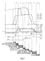
- the rotational speed of the internal combustion engine is shown at n_VM, the rotational speed of the electric machine at n_EM, the rotational speed at the input of the first partial transmission 32 at n_TG1, and the rotational speed at the input of the second partial transmission at n_TG2.
- the speeds n_EM and n_TG2 are identical or proportional, since the electric machine 40 in this case is fixedly coupled to the input of the second partial transmission 22 (TG2) or to the output of the second friction clutch 20 (K2).
- tq_VM is the torque of the engine
- tq_EM is the torque of the electric machine
- tq_K1 is the torque transmitted from the first friction clutch 30 (K1)
- tq_K2 is the torque, which is transmitted from the second friction clutch 20 (K2).
- time charts show the gear changes, which are shown in the respective partial transmissions TG1, TG2, where G stands for gear stage and where N stands for neutral position.
- G stands for gear stage
- N stands for neutral position.
- the timing diagrams described below are partially normalized in terms of speed and torque, so that the different ratios are eliminated to make the operations more understandable. This is especially true for the timing diagram of Fig. 5 ,
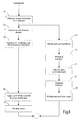
- FIG. 2 shows a flow chart or flow chart
- Fig. 3 shows a graph of speeds and torques and shifts in the powertrain over time.
- a first step (Phase 1 in Fig. 3 and step A1 in Fig. 2 ) first in the first partial transmission 1 (passive partial transmission) from the neutral position as high a gear engaged (grade 3 or 5).
- step A3 the torque of the electric machine is increased to compensate for the drag torque of the internal combustion engine.
- step A2 the cranking or towing of the internal combustion engine can take place by means of the clutch K2. If the drive train has a starter motor 44, however, this turning can also take place by means of the starter motor 44.
- phase 3 of the Fig. 3 the speed of the internal combustion engine has reached the target speed, so that subsequently the clutch K2 can be opened (A4 in FIG Fig. 2 ), and the moment of the electric machine can be shut down. If the starter motor 44 has been used for towing the internal combustion engine, the clutch K2 has not necessarily been closed and consequently does not necessarily have to be reopened.
- step A6 phase 4 in FIG Fig. 3
- step A8 the speed of the electric machine 40
- target gear change gear can be engaged (in phase 6 of Fig. 3 and step A9, target gear is gear 4).
- the torque of the electric machine 40 can in turn be increased to a target torque (phase 7 in FIG Fig. 3 and step A10).
- a preselection gear can already be engaged.
- the procedure of Fig. 2 is therefore based on providing a filling moment by not firing the internal combustion engine, but first towing it so that its momentum energy can be used to provide a filling moment.
- This is in contrast to the procedures of the document DE 10 2010 044 618 A1 a relatively high gear engaged (in this case, the gear 3 or 5 and not the gear 1), which is the second highest or highest gear.
- the torque to be provided by the electric motor 40 for compensation of the drag torque may be lower, so that more torque can be provided in the phases 1 and 2 as well as partly 3 for the drive of the motor vehicle.
- a higher torque can generally be provided by the electric machine for driving the motor vehicle during these phases.
- FIG. 4 and 5 Another embodiment of a method according to the invention is in the Fig. 4 and 5 shown.
- a filling torque is provided by the electric machine 40, wherein this filling torque is guided via the second friction clutch 20 and the first friction clutch 30 on the first power transmission path 36.
- the drive motor 12 is forcibly dragged, so that this Mitschleppmoment must also be compensated.
- the method initially starts with the engagement of a higher gear stage (eg gear stage 5) in the partial transmission 1 (step B1 in FIG Fig. 4 , Phase 1 in Fig. 5 ).
- a higher gear stage eg gear stage 5
- the torque of the electric machine is increased in this phase.
- the second friction clutch 20 (K2) is ramped closed so that the electric machine 40 transfers torque via the second friction clutch 20 and the first friction clutch 30 into the first power transmission path 36. In this case, therefore, the moment of the electric machine 40 is adapted.
- the Fig. 4 (Phases 4 to 6 in Fig. 5 ) the gear change from the starting gear (G2) in the target gear (G4) of the partial transmission 2 done.
- the first friction clutch 30 can then be opened (step B12 in FIG Fig. 4 ), and in parallel, the torque of the electric machine 40 is guided to a target torque (step B13).
- step B14 a target gear stage can be engaged in the first partial transmission, or else a change to a neutral position can take place, as in phase 9 of FIG Fig. 5 shown.
- a further embodiment of a method according to the invention is shown, in which the drive motor is designed as an internal combustion engine and this is not only towed, but also ignited to provide a filling torque by means of the ignited internal combustion engine.
- step C1 a higher gear stage is engaged in the first partial transmission 32 (G3 in phase 1 of FIG Fig. 7 ).
- the second friction clutch K2 is closed so that the internal combustion engine is pulled up (phase 2 in FIG Fig. 7 and step C2 in Fig. 6 ).
- the torque of the electric machine 40 is increased to compensate for the drag torque of the internal combustion engine (step C3).
- the second friction clutch 20 is opened and the first friction clutch 30 is closed. Fill moment is now provided by means of the internal combustion engine via the first power transmission path 36.
- the torque of the electric machine 40 may be shut down (step C5), and the gear shift may be performed in a conventional manner (steps C6 to C8, phases 4 to 6 of FIG Fig. 7 ).
- step C10 the first friction clutch is opened again and in parallel the torque of the electric machine 40 is increased (C9, phase 7 in FIG Fig. 7 ).
- step C11 the internal combustion engine can then be switched off again.
- the duration for which the internal combustion engine is ignited is limited to the time range of the gear change and may in particular be shorter than one second, in particular shorter than half a second.
- FIG. 8 and 9 a further embodiment of a method according to the invention is shown, which essentially corresponds to the method of Fig. 6 and 7 equivalent.
- step D2 the burner is started by means of a starter motor, which is present in this variant in the drive train.
- Step D3 corresponding to step C4 of FIG Fig. 6
- Steps D4 to D7 correspond to steps C5 to C8 of FIG Fig. 6 .
- Steps D9 to D10 correspond to steps C9 to C11 of FIG Fig. 6 .
Landscapes
- Engineering & Computer Science (AREA)
- Mechanical Engineering (AREA)
- Chemical & Material Sciences (AREA)
- Combustion & Propulsion (AREA)
- Transportation (AREA)
- Automation & Control Theory (AREA)
- General Engineering & Computer Science (AREA)
- Hybrid Electric Vehicles (AREA)
- Electric Propulsion And Braking For Vehicles (AREA)
- Control Of Vehicle Engines Or Engines For Specific Uses (AREA)
- Arrangement Of Transmissions (AREA)
Applications Claiming Priority (1)
| Application Number | Priority Date | Filing Date | Title |
|---|---|---|---|
| DE201210018416 DE102012018416B4 (de) | 2012-09-12 | 2012-09-12 | Verfahren zum Ansteuern eines Hybridantriebsstranges |
Publications (3)
| Publication Number | Publication Date |
|---|---|
| EP2708400A2 true EP2708400A2 (fr) | 2014-03-19 |
| EP2708400A3 EP2708400A3 (fr) | 2015-11-11 |
| EP2708400B1 EP2708400B1 (fr) | 2021-07-28 |
Family
ID=49035445
Family Applications (1)
| Application Number | Title | Priority Date | Filing Date |
|---|---|---|---|
| EP13181926.0A Active EP2708400B1 (fr) | 2012-09-12 | 2013-08-28 | Procédé destiné à la commande d'une chaîne d'entraînement hybride |
Country Status (4)
| Country | Link |
|---|---|
| US (1) | US9120481B2 (fr) |
| EP (1) | EP2708400B1 (fr) |
| CN (1) | CN103661362B (fr) |
| DE (1) | DE102012018416B4 (fr) |
Cited By (2)
| Publication number | Priority date | Publication date | Assignee | Title |
|---|---|---|---|---|
| WO2018087438A1 (fr) * | 2016-11-14 | 2018-05-17 | Renault S.A.S | Dispositif et procédé de pilotage d'une boite de vitesses robotisee pour vehicule automobile a propulsion hybride |
| WO2021063626A1 (fr) * | 2019-09-30 | 2021-04-08 | Magna Pt B.V. & Co. Kg | Procédé de fonctionnement d'une transmission hybride en cas de besoin de couple de démarrage élevé et dispositif de commande |
Families Citing this family (14)
| Publication number | Priority date | Publication date | Assignee | Title |
|---|---|---|---|---|
| KR101637687B1 (ko) * | 2014-09-29 | 2016-07-08 | 현대자동차주식회사 | 차량의 하이브리드 변속기 |
| DE102017100683A1 (de) | 2017-01-16 | 2018-07-19 | GETRAG B.V. & Co. KG | Verfahren zur Einrückpunkt-Ermittlung einer Reibkupplung in einem Hybrid-Antriebsstrang |
| US10518767B2 (en) * | 2017-02-24 | 2019-12-31 | Ford Global Technologies, Llc | Systems and methods for controlling an engine start in a hybrid vehicle |
| DE102017104106A1 (de) * | 2017-02-28 | 2018-08-30 | GETRAG B.V. & Co. KG | Verfahren zum Ansteuern eines Hybrid-Antriebsstranges |
| DE102017130707A1 (de) | 2017-12-20 | 2019-06-27 | GETRAG B.V. & Co. KG | Verfahren zum Betreiben eines Hybrid-Antriebsstranges sowie Hybrid-Antriebsstrang für ein Kraftfahrzeug |
| DE102018208084A1 (de) * | 2018-05-23 | 2019-11-28 | Magna Pt B.V. & Co. Kg | Antriebsstrang für ein Kraftfahrzeug und Verfahren zum Betreiben desselben |
| DE102019100503A1 (de) * | 2019-01-10 | 2020-07-16 | Bayerische Motoren Werke Aktiengesellschaft | Steuereinheit und Verfahren zum Betrieb eines Hybridantriebs mit einem Doppelkupplungsgetriebe |
| DE102020202141A1 (de) | 2020-02-19 | 2021-08-19 | Magna Pt B.V. & Co. Kg | Doppelkupplungssystem sowie Verfahren zum Betrieb eines solchen |
| DE102020202138B4 (de) | 2020-02-19 | 2022-03-31 | Magna Pt B.V. & Co. Kg | Hybrid-Antriebsstrang für ein Kraftfahrzeug mit Trennelement |
| DE102020202139B4 (de) | 2020-02-19 | 2022-04-14 | Magna Pt B.V. & Co. Kg | Hybrid-Antriebsstrang für ein Kraftfahrzeug mit Trennelement |
| DE102020202150B4 (de) | 2020-02-19 | 2022-04-14 | Magna Pt B.V. & Co. Kg | Verfahren zum Betrieb eines Hybrid-Antriebsstrangs für ein Kraftfahrzeug mit hydraulischer Betätigung für ein Trennelement |
| DE102020206020A1 (de) | 2020-05-13 | 2021-11-18 | Magna Pt B.V. & Co. Kg | Verfahren zum Ansteuern eines Hybridantriebsstrangs |
| DE102020209763B4 (de) | 2020-08-03 | 2023-02-09 | Magna Pt B.V. & Co. Kg | Hybrid-Antriebsstrang für ein Kraftfahrzeug sowie Verfahren zum Starten |
| CN112721905B (zh) * | 2021-01-07 | 2022-04-08 | 浙江吉利控股集团有限公司 | 双电机混合动力系统中发动机的启动方法和装置及车辆 |
Citations (1)
| Publication number | Priority date | Publication date | Assignee | Title |
|---|---|---|---|---|
| DE102010044618A1 (de) | 2010-08-27 | 2012-03-01 | Getrag Getriebe- Und Zahnradfabrik Hermann Hagenmeyer Gmbh & Cie Kg | Verfahren zum Ansteuern eines Hybrid-Antriebsstranges |
Family Cites Families (15)
| Publication number | Priority date | Publication date | Assignee | Title |
|---|---|---|---|---|
| EP1714817A1 (fr) * | 2005-04-19 | 2006-10-25 | Getrag Ford Transmissions GmbH | Système d'entraînement hybride avec deux embrayages |
| DE102005048938A1 (de) * | 2005-10-13 | 2007-04-19 | Volkswagen Ag | Doppelkupplungsgetriebe für ein Kraftfahrzeug, insbesondere mit einem Hybridantrieb bzw. Verfahren zur Steuerung dieses Doppelkupplungsgetriebes |
| JP4961192B2 (ja) * | 2006-11-09 | 2012-06-27 | アイシン精機株式会社 | 車両の駆動源制御装置 |
| US8170764B2 (en) * | 2007-11-02 | 2012-05-01 | GM Global Technology Operations LLC | Method and apparatus to reprofile input speed during speed during speed phase during constrained conditions for a hybrid powertrain system |
| DE102008027658A1 (de) * | 2008-06-10 | 2009-12-17 | Bayerische Motoren Werke Aktiengesellschaft | Verfahren zum Starten einer Brennkraftmaschine eines Hybridfahrzeugs |
| US8137236B2 (en) * | 2008-06-27 | 2012-03-20 | Ford Global Technologies, Llc | Ouput torque modulation control of a transmission in a hybrid electric vehicle |
| DE102008041565A1 (de) * | 2008-08-26 | 2010-03-04 | Robert Bosch Gmbh | Verfahren zum Betreiben einer Hybridantriebsvorrichtung eines Kraftfahrzeugs sowie Hybridantriebsvorrichtung und elektronisches Steuergerät |
| DE102009002176B4 (de) * | 2009-04-03 | 2017-07-20 | Robert Bosch Gmbh | Verfahren und Vorrichtung zum Betreiben eines Hybridfahrzeuges |
| GB0918380D0 (en) * | 2009-10-20 | 2009-12-02 | Ricardo Uk Ltd | Torque fill-in |
| GB0918384D0 (en) * | 2009-10-20 | 2009-12-02 | Ricardo Uk Ltd | A dual-mode battery |
| WO2011048141A1 (fr) * | 2009-10-20 | 2011-04-28 | Ricardo Uk Limited | Gestion de l'énergie |
| GB2476109A (en) * | 2009-12-14 | 2011-06-15 | Gm Global Tech Operations Inc | Hybrid vehicle which uses electric motor to smooth gear changes |
| DE102010030569A1 (de) * | 2010-06-28 | 2011-12-29 | Zf Friedrichshafen Ag | Hybridantrieb eines Kraftfahrzeugs und Verfahren zu dessen Steuerung |
| KR101521761B1 (ko) * | 2011-08-09 | 2015-05-19 | 도요타지도샤가부시키가이샤 | 하이브리드 차량의 제어 장치 |
| US8777789B2 (en) * | 2012-01-04 | 2014-07-15 | Zf Friedrichshafen Ag | Split axis transmission hybrid system architecture |
-
2012
- 2012-09-12 DE DE201210018416 patent/DE102012018416B4/de active Active
-
2013
- 2013-08-28 EP EP13181926.0A patent/EP2708400B1/fr active Active
- 2013-09-11 US US14/024,487 patent/US9120481B2/en not_active Expired - Fee Related
- 2013-09-12 CN CN201310415093.XA patent/CN103661362B/zh active Active
Patent Citations (1)
| Publication number | Priority date | Publication date | Assignee | Title |
|---|---|---|---|---|
| DE102010044618A1 (de) | 2010-08-27 | 2012-03-01 | Getrag Getriebe- Und Zahnradfabrik Hermann Hagenmeyer Gmbh & Cie Kg | Verfahren zum Ansteuern eines Hybrid-Antriebsstranges |
Cited By (5)
| Publication number | Priority date | Publication date | Assignee | Title |
|---|---|---|---|---|
| WO2018087438A1 (fr) * | 2016-11-14 | 2018-05-17 | Renault S.A.S | Dispositif et procédé de pilotage d'une boite de vitesses robotisee pour vehicule automobile a propulsion hybride |
| FR3058698A1 (fr) * | 2016-11-14 | 2018-05-18 | Renault S.A.S | Dispositif de pilotage d'une boite de vitesses robotisee pour vehicule automobile a propulsion hybride |
| KR20190100188A (ko) * | 2016-11-14 | 2019-08-28 | 르노 에스.아.에스. | 하이브리드 모터 차량의 반자동 기어박스를 제어하는 방법 및 장치 |
| CN110312627A (zh) * | 2016-11-14 | 2019-10-08 | 雷诺股份公司 | 用于控制混合动力机动车辆半自动变速箱的方法和装置 |
| WO2021063626A1 (fr) * | 2019-09-30 | 2021-04-08 | Magna Pt B.V. & Co. Kg | Procédé de fonctionnement d'une transmission hybride en cas de besoin de couple de démarrage élevé et dispositif de commande |
Also Published As
| Publication number | Publication date |
|---|---|
| US20140073480A1 (en) | 2014-03-13 |
| DE102012018416A1 (de) | 2014-03-13 |
| DE102012018416B4 (de) | 2015-04-23 |
| EP2708400A3 (fr) | 2015-11-11 |
| CN103661362A (zh) | 2014-03-26 |
| CN103661362B (zh) | 2018-02-16 |
| EP2708400B1 (fr) | 2021-07-28 |
| US9120481B2 (en) | 2015-09-01 |
Similar Documents
| Publication | Publication Date | Title |
|---|---|---|
| DE102012018416B4 (de) | Verfahren zum Ansteuern eines Hybridantriebsstranges | |
| DE102010044618B4 (de) | Verfahren zum Ansteuern eines Hybrid-Antriebsstranges | |
| EP2765338B1 (fr) | Procédé destiné au fonctionnement d'une chaîne cinématique hybridée de boîte de vitesses à double embrayage | |
| EP2655111B1 (fr) | Dispositif pour une chaîne cinématique d'un véhicule hybride, chaîne cinématique et procédé permettant de faire fonctionner cette chaîne | |
| EP2511147B1 (fr) | Procédé destiné au fonctionnement d'une chaîne cinématique hybride | |
| EP2794317B1 (fr) | Entraînement hybride d'un véhicule automobile et son procédé de fonctionnement | |
| DE102008025516A1 (de) | Steuerung von Doppelstufenschaltvorgängen bei einem Hybridfahrzeug | |
| EP3359435A1 (fr) | Procédé et dispositif pour faire fonctionner un système de propulsion, système de propulsion | |
| EP2757005A2 (fr) | Procédé de retenue d'un véhicule automobile sur une pente | |
| DE102017216984A1 (de) | Verfahren zur Ansteuerung eines Stufengetriebes und eines Antriebsstranges, sowie Steuereinrichtung und Antriebsstrang | |
| DE102020203803A1 (de) | Hybridgetriebe mit elektrischer Zugkraftunterstützung | |
| DE102017214121A1 (de) | Verfahren zum Ansteuern eines Antriebsstranges für ein Kraftfahrzeug sowie Steuereinrichtung | |
| EP3797231B1 (fr) | Chaîne cinématique d'un véhicule automobile et procédé pour faire fonctionner une chaîne cinématique | |
| WO2021228665A1 (fr) | Procédé de commande d'une chaîne cinématique hybride | |
| DE102022201154A1 (de) | Dreigang-Hybridgetriebe | |
| DE102022202381A1 (de) | Dreigang-Hybridgetriebe | |
| WO2020249307A1 (fr) | Boîte de vitesses pour un système de propulsion hybride, système de propulsion hybride, véhicule, et procédé de fonctionnement du système de propulsion hybride | |
| DE102022202924A1 (de) | Hybridgetriebe | |
| DE102022202919A1 (de) | Kompaktes Hybridgetriebe | |
| DE102020203179A1 (de) | Hybridgetriebe mit elektrischer Zugkraftunterstützung | |
| WO2020249337A1 (fr) | Boîte de vitesses pour un système de propulsion hybride, système de propulsion hybride, véhicule, et procédé de fonctionnement du système de propulsion hybride | |
| WO2022128216A1 (fr) | Stratégie de commutation pour transmission hybride à essieu électrique | |
| DE102022201151A1 (de) | Kompaktes Hybridgetriebe | |
| WO2020249336A1 (fr) | Transmission pour un ensemble d'entraînement hybride, ensemble d'entraînement hybride, véhicule, et procédé pour faire fonctionner l'ensemble d'entraînement hybride | |
| DE102020203773A1 (de) | Mehrgängiges Planetengetriebe |
Legal Events
| Date | Code | Title | Description |
|---|---|---|---|
| PUAI | Public reference made under article 153(3) epc to a published international application that has entered the european phase |
Free format text: ORIGINAL CODE: 0009012 |
|
| AK | Designated contracting states |
Kind code of ref document: A2 Designated state(s): AL AT BE BG CH CY CZ DE DK EE ES FI FR GB GR HR HU IE IS IT LI LT LU LV MC MK MT NL NO PL PT RO RS SE SI SK SM TR |
|
| AX | Request for extension of the european patent |
Extension state: BA ME |
|
| PUAL | Search report despatched |
Free format text: ORIGINAL CODE: 0009013 |
|
| AK | Designated contracting states |
Kind code of ref document: A3 Designated state(s): AL AT BE BG CH CY CZ DE DK EE ES FI FR GB GR HR HU IE IS IT LI LT LU LV MC MK MT NL NO PL PT RO RS SE SI SK SM TR |
|
| AX | Request for extension of the european patent |
Extension state: BA ME |
|
| RIC1 | Information provided on ipc code assigned before grant |
Ipc: B60W 10/06 20060101ALI20151007BHEP Ipc: B60W 10/08 20060101ALI20151007BHEP Ipc: B60W 10/113 20120101ALI20151007BHEP Ipc: F02N 11/00 20060101ALI20151007BHEP Ipc: B60W 30/19 20120101ALI20151007BHEP Ipc: B60W 20/00 20060101ALI20151007BHEP Ipc: B60W 30/192 20120101ALI20151007BHEP Ipc: B60K 6/48 20071001AFI20151007BHEP |
|
| 17P | Request for examination filed |
Effective date: 20160510 |
|
| RBV | Designated contracting states (corrected) |
Designated state(s): AL AT BE BG CH CY CZ DE DK EE ES FI FR GB GR HR HU IE IS IT LI LT LU LV MC MK MT NL NO PL PT RO RS SE SI SK SM TR |
|
| STAA | Information on the status of an ep patent application or granted ep patent |
Free format text: STATUS: EXAMINATION IS IN PROGRESS |
|
| 17Q | First examination report despatched |
Effective date: 20170202 |
|
| RAP1 | Party data changed (applicant data changed or rights of an application transferred) |
Owner name: GETRAG B.V. & CO. KG |
|
| STAA | Information on the status of an ep patent application or granted ep patent |
Free format text: STATUS: EXAMINATION IS IN PROGRESS |
|
| RIC1 | Information provided on ipc code assigned before grant |
Ipc: B60W 20/00 20160101ALI20151007BHEP Ipc: B60W 30/192 20120101ALI20151007BHEP Ipc: B60W 10/113 20120101ALI20151007BHEP Ipc: F02N 11/00 20060101ALI20151007BHEP Ipc: B60W 30/19 20120101ALI20151007BHEP Ipc: B60W 10/08 20060101ALI20151007BHEP Ipc: B60K 6/48 20071001AFI20151007BHEP Ipc: B60W 10/06 20060101ALI20151007BHEP |
|
| RAP1 | Party data changed (applicant data changed or rights of an application transferred) |
Owner name: MAGNA PT B.V. & CO. KG |
|
| APBK | Appeal reference recorded |
Free format text: ORIGINAL CODE: EPIDOSNREFNE |
|
| APBN | Date of receipt of notice of appeal recorded |
Free format text: ORIGINAL CODE: EPIDOSNNOA2E |
|
| APBR | Date of receipt of statement of grounds of appeal recorded |
Free format text: ORIGINAL CODE: EPIDOSNNOA3E |
|
| APAF | Appeal reference modified |
Free format text: ORIGINAL CODE: EPIDOSCREFNE |
|
| APBX | Invitation to file observations in appeal sent |
Free format text: ORIGINAL CODE: EPIDOSNOBA2E |
|
| APBZ | Receipt of observations in appeal recorded |
Free format text: ORIGINAL CODE: EPIDOSNOBA4E |
|
| APBT | Appeal procedure closed |
Free format text: ORIGINAL CODE: EPIDOSNNOA9E |
|
| GRAP | Despatch of communication of intention to grant a patent |
Free format text: ORIGINAL CODE: EPIDOSNIGR1 |
|
| STAA | Information on the status of an ep patent application or granted ep patent |
Free format text: STATUS: GRANT OF PATENT IS INTENDED |
|
| INTG | Intention to grant announced |
Effective date: 20210318 |
|
| GRAS | Grant fee paid |
Free format text: ORIGINAL CODE: EPIDOSNIGR3 |
|
| GRAA | (expected) grant |
Free format text: ORIGINAL CODE: 0009210 |
|
| STAA | Information on the status of an ep patent application or granted ep patent |
Free format text: STATUS: THE PATENT HAS BEEN GRANTED |
|
| AK | Designated contracting states |
Kind code of ref document: B1 Designated state(s): AL AT BE BG CH CY CZ DE DK EE ES FI FR GB GR HR HU IE IS IT LI LT LU LV MC MK MT NL NO PL PT RO RS SE SI SK SM TR |
|
| REG | Reference to a national code |
Ref country code: GB Ref legal event code: FG4D Free format text: NOT ENGLISH |
|
| REG | Reference to a national code |
Ref country code: CH Ref legal event code: EP |
|
| REG | Reference to a national code |
Ref country code: AT Ref legal event code: REF Ref document number: 1414423 Country of ref document: AT Kind code of ref document: T Effective date: 20210815 |
|
| REG | Reference to a national code |
Ref country code: IE Ref legal event code: FG4D Free format text: LANGUAGE OF EP DOCUMENT: GERMAN |
|
| REG | Reference to a national code |
Ref country code: DE Ref legal event code: R096 Ref document number: 502013015848 Country of ref document: DE |
|
| REG | Reference to a national code |
Ref country code: LT Ref legal event code: MG9D |
|
| REG | Reference to a national code |
Ref country code: NL Ref legal event code: MP Effective date: 20210728 |
|
| PG25 | Lapsed in a contracting state [announced via postgrant information from national office to epo] |
Ref country code: HR Free format text: LAPSE BECAUSE OF FAILURE TO SUBMIT A TRANSLATION OF THE DESCRIPTION OR TO PAY THE FEE WITHIN THE PRESCRIBED TIME-LIMIT Effective date: 20210728 Ref country code: SE Free format text: LAPSE BECAUSE OF FAILURE TO SUBMIT A TRANSLATION OF THE DESCRIPTION OR TO PAY THE FEE WITHIN THE PRESCRIBED TIME-LIMIT Effective date: 20210728 Ref country code: LT Free format text: LAPSE BECAUSE OF FAILURE TO SUBMIT A TRANSLATION OF THE DESCRIPTION OR TO PAY THE FEE WITHIN THE PRESCRIBED TIME-LIMIT Effective date: 20210728 Ref country code: BG Free format text: LAPSE BECAUSE OF FAILURE TO SUBMIT A TRANSLATION OF THE DESCRIPTION OR TO PAY THE FEE WITHIN THE PRESCRIBED TIME-LIMIT Effective date: 20211028 Ref country code: NL Free format text: LAPSE BECAUSE OF FAILURE TO SUBMIT A TRANSLATION OF THE DESCRIPTION OR TO PAY THE FEE WITHIN THE PRESCRIBED TIME-LIMIT Effective date: 20210728 Ref country code: RS Free format text: LAPSE BECAUSE OF FAILURE TO SUBMIT A TRANSLATION OF THE DESCRIPTION OR TO PAY THE FEE WITHIN THE PRESCRIBED TIME-LIMIT Effective date: 20210728 Ref country code: NO Free format text: LAPSE BECAUSE OF FAILURE TO SUBMIT A TRANSLATION OF THE DESCRIPTION OR TO PAY THE FEE WITHIN THE PRESCRIBED TIME-LIMIT Effective date: 20211028 Ref country code: PT Free format text: LAPSE BECAUSE OF FAILURE TO SUBMIT A TRANSLATION OF THE DESCRIPTION OR TO PAY THE FEE WITHIN THE PRESCRIBED TIME-LIMIT Effective date: 20211129 Ref country code: ES Free format text: LAPSE BECAUSE OF FAILURE TO SUBMIT A TRANSLATION OF THE DESCRIPTION OR TO PAY THE FEE WITHIN THE PRESCRIBED TIME-LIMIT Effective date: 20210728 Ref country code: FI Free format text: LAPSE BECAUSE OF FAILURE TO SUBMIT A TRANSLATION OF THE DESCRIPTION OR TO PAY THE FEE WITHIN THE PRESCRIBED TIME-LIMIT Effective date: 20210728 |
|
| PG25 | Lapsed in a contracting state [announced via postgrant information from national office to epo] |
Ref country code: PL Free format text: LAPSE BECAUSE OF FAILURE TO SUBMIT A TRANSLATION OF THE DESCRIPTION OR TO PAY THE FEE WITHIN THE PRESCRIBED TIME-LIMIT Effective date: 20210728 Ref country code: LV Free format text: LAPSE BECAUSE OF FAILURE TO SUBMIT A TRANSLATION OF THE DESCRIPTION OR TO PAY THE FEE WITHIN THE PRESCRIBED TIME-LIMIT Effective date: 20210728 Ref country code: GR Free format text: LAPSE BECAUSE OF FAILURE TO SUBMIT A TRANSLATION OF THE DESCRIPTION OR TO PAY THE FEE WITHIN THE PRESCRIBED TIME-LIMIT Effective date: 20211029 |
|
| REG | Reference to a national code |
Ref country code: CH Ref legal event code: PL |
|
| PG25 | Lapsed in a contracting state [announced via postgrant information from national office to epo] |
Ref country code: LI Free format text: LAPSE BECAUSE OF NON-PAYMENT OF DUE FEES Effective date: 20210831 Ref country code: DK Free format text: LAPSE BECAUSE OF FAILURE TO SUBMIT A TRANSLATION OF THE DESCRIPTION OR TO PAY THE FEE WITHIN THE PRESCRIBED TIME-LIMIT Effective date: 20210728 Ref country code: CH Free format text: LAPSE BECAUSE OF NON-PAYMENT OF DUE FEES Effective date: 20210831 |
|
| REG | Reference to a national code |
Ref country code: DE Ref legal event code: R097 Ref document number: 502013015848 Country of ref document: DE |
|
| PG25 | Lapsed in a contracting state [announced via postgrant information from national office to epo] |
Ref country code: SM Free format text: LAPSE BECAUSE OF FAILURE TO SUBMIT A TRANSLATION OF THE DESCRIPTION OR TO PAY THE FEE WITHIN THE PRESCRIBED TIME-LIMIT Effective date: 20210728 Ref country code: SK Free format text: LAPSE BECAUSE OF FAILURE TO SUBMIT A TRANSLATION OF THE DESCRIPTION OR TO PAY THE FEE WITHIN THE PRESCRIBED TIME-LIMIT Effective date: 20210728 Ref country code: RO Free format text: LAPSE BECAUSE OF FAILURE TO SUBMIT A TRANSLATION OF THE DESCRIPTION OR TO PAY THE FEE WITHIN THE PRESCRIBED TIME-LIMIT Effective date: 20210728 Ref country code: MC Free format text: LAPSE BECAUSE OF FAILURE TO SUBMIT A TRANSLATION OF THE DESCRIPTION OR TO PAY THE FEE WITHIN THE PRESCRIBED TIME-LIMIT Effective date: 20210728 Ref country code: LU Free format text: LAPSE BECAUSE OF NON-PAYMENT OF DUE FEES Effective date: 20210828 Ref country code: EE Free format text: LAPSE BECAUSE OF FAILURE TO SUBMIT A TRANSLATION OF THE DESCRIPTION OR TO PAY THE FEE WITHIN THE PRESCRIBED TIME-LIMIT Effective date: 20210728 Ref country code: CZ Free format text: LAPSE BECAUSE OF FAILURE TO SUBMIT A TRANSLATION OF THE DESCRIPTION OR TO PAY THE FEE WITHIN THE PRESCRIBED TIME-LIMIT Effective date: 20210728 Ref country code: AL Free format text: LAPSE BECAUSE OF FAILURE TO SUBMIT A TRANSLATION OF THE DESCRIPTION OR TO PAY THE FEE WITHIN THE PRESCRIBED TIME-LIMIT Effective date: 20210728 |
|
| PLBE | No opposition filed within time limit |
Free format text: ORIGINAL CODE: 0009261 |
|
| STAA | Information on the status of an ep patent application or granted ep patent |
Free format text: STATUS: NO OPPOSITION FILED WITHIN TIME LIMIT |
|
| GBPC | Gb: european patent ceased through non-payment of renewal fee |
Effective date: 20211028 |
|
| 26N | No opposition filed |
Effective date: 20220429 |
|
| PG25 | Lapsed in a contracting state [announced via postgrant information from national office to epo] |
Ref country code: IT Free format text: LAPSE BECAUSE OF FAILURE TO SUBMIT A TRANSLATION OF THE DESCRIPTION OR TO PAY THE FEE WITHIN THE PRESCRIBED TIME-LIMIT Effective date: 20210728 Ref country code: IE Free format text: LAPSE BECAUSE OF NON-PAYMENT OF DUE FEES Effective date: 20210828 Ref country code: GB Free format text: LAPSE BECAUSE OF NON-PAYMENT OF DUE FEES Effective date: 20211028 |
|
| REG | Reference to a national code |
Ref country code: AT Ref legal event code: MM01 Ref document number: 1414423 Country of ref document: AT Kind code of ref document: T Effective date: 20210828 |
|
| PG25 | Lapsed in a contracting state [announced via postgrant information from national office to epo] |
Ref country code: AT Free format text: LAPSE BECAUSE OF NON-PAYMENT OF DUE FEES Effective date: 20210828 |
|
| PG25 | Lapsed in a contracting state [announced via postgrant information from national office to epo] |
Ref country code: HU Free format text: LAPSE BECAUSE OF FAILURE TO SUBMIT A TRANSLATION OF THE DESCRIPTION OR TO PAY THE FEE WITHIN THE PRESCRIBED TIME-LIMIT; INVALID AB INITIO Effective date: 20130828 |
|
| PG25 | Lapsed in a contracting state [announced via postgrant information from national office to epo] |
Ref country code: CY Free format text: LAPSE BECAUSE OF FAILURE TO SUBMIT A TRANSLATION OF THE DESCRIPTION OR TO PAY THE FEE WITHIN THE PRESCRIBED TIME-LIMIT Effective date: 20210728 |
|
| PGFP | Annual fee paid to national office [announced via postgrant information from national office to epo] |
Ref country code: FR Payment date: 20230824 Year of fee payment: 11 Ref country code: DE Payment date: 20230821 Year of fee payment: 11 Ref country code: BE Payment date: 20230821 Year of fee payment: 11 |
|
| PG25 | Lapsed in a contracting state [announced via postgrant information from national office to epo] |
Ref country code: MK Free format text: LAPSE BECAUSE OF FAILURE TO SUBMIT A TRANSLATION OF THE DESCRIPTION OR TO PAY THE FEE WITHIN THE PRESCRIBED TIME-LIMIT Effective date: 20210728 |