EP2708400A2 - Method for controlling a hybrid power train - Google Patents
Method for controlling a hybrid power train Download PDFInfo
- Publication number
- EP2708400A2 EP2708400A2 EP20130181926 EP13181926A EP2708400A2 EP 2708400 A2 EP2708400 A2 EP 2708400A2 EP 20130181926 EP20130181926 EP 20130181926 EP 13181926 A EP13181926 A EP 13181926A EP 2708400 A2 EP2708400 A2 EP 2708400A2
- Authority
- EP
- European Patent Office
- Prior art keywords
- torque
- drive motor
- friction clutch
- electric machine
- gear
- Prior art date
- Legal status (The legal status is an assumption and is not a legal conclusion. Google has not performed a legal analysis and makes no representation as to the accuracy of the status listed.)
- Granted
Links
- 238000000034 method Methods 0.000 title claims abstract description 38
- 230000005540 biological transmission Effects 0.000 claims abstract description 92
- 239000007858 starting material Substances 0.000 claims abstract description 31
- 230000008859 change Effects 0.000 claims description 27
- 230000009977 dual effect Effects 0.000 claims description 3
- 238000002485 combustion reaction Methods 0.000 description 38
- 238000010586 diagram Methods 0.000 description 9
- 230000007935 neutral effect Effects 0.000 description 4
- 230000008878 coupling Effects 0.000 description 3
- 238000010168 coupling process Methods 0.000 description 3
- 238000005859 coupling reaction Methods 0.000 description 3
- 230000001133 acceleration Effects 0.000 description 2
- 238000001994 activation Methods 0.000 description 1
- 230000008901 benefit Effects 0.000 description 1
- 238000010304 firing Methods 0.000 description 1
- 239000002828 fuel tank Substances 0.000 description 1
- 238000003780 insertion Methods 0.000 description 1
- 230000037431 insertion Effects 0.000 description 1
- 238000009434 installation Methods 0.000 description 1
- 238000002955 isolation Methods 0.000 description 1
- 230000008569 process Effects 0.000 description 1
- 230000001360 synchronised effect Effects 0.000 description 1
Images


Classifications
-
- B—PERFORMING OPERATIONS; TRANSPORTING
- B60—VEHICLES IN GENERAL
- B60W—CONJOINT CONTROL OF VEHICLE SUB-UNITS OF DIFFERENT TYPE OR DIFFERENT FUNCTION; CONTROL SYSTEMS SPECIALLY ADAPTED FOR HYBRID VEHICLES; ROAD VEHICLE DRIVE CONTROL SYSTEMS FOR PURPOSES NOT RELATED TO THE CONTROL OF A PARTICULAR SUB-UNIT
- B60W20/00—Control systems specially adapted for hybrid vehicles
- B60W20/10—Controlling the power contribution of each of the prime movers to meet required power demand
-
- F—MECHANICAL ENGINEERING; LIGHTING; HEATING; WEAPONS; BLASTING
- F16—ENGINEERING ELEMENTS AND UNITS; GENERAL MEASURES FOR PRODUCING AND MAINTAINING EFFECTIVE FUNCTIONING OF MACHINES OR INSTALLATIONS; THERMAL INSULATION IN GENERAL
- F16H—GEARING
- F16H61/00—Control functions within control units of change-speed- or reversing-gearings for conveying rotary motion ; Control of exclusively fluid gearing, friction gearing, gearings with endless flexible members or other particular types of gearing
- F16H61/68—Control functions within control units of change-speed- or reversing-gearings for conveying rotary motion ; Control of exclusively fluid gearing, friction gearing, gearings with endless flexible members or other particular types of gearing specially adapted for stepped gearings
- F16H61/684—Control functions within control units of change-speed- or reversing-gearings for conveying rotary motion ; Control of exclusively fluid gearing, friction gearing, gearings with endless flexible members or other particular types of gearing specially adapted for stepped gearings without interruption of drive
- F16H61/688—Control functions within control units of change-speed- or reversing-gearings for conveying rotary motion ; Control of exclusively fluid gearing, friction gearing, gearings with endless flexible members or other particular types of gearing specially adapted for stepped gearings without interruption of drive with two inputs, e.g. selection of one of two torque-flow paths by clutches
-
- B—PERFORMING OPERATIONS; TRANSPORTING
- B60—VEHICLES IN GENERAL
- B60K—ARRANGEMENT OR MOUNTING OF PROPULSION UNITS OR OF TRANSMISSIONS IN VEHICLES; ARRANGEMENT OR MOUNTING OF PLURAL DIVERSE PRIME-MOVERS IN VEHICLES; AUXILIARY DRIVES FOR VEHICLES; INSTRUMENTATION OR DASHBOARDS FOR VEHICLES; ARRANGEMENTS IN CONNECTION WITH COOLING, AIR INTAKE, GAS EXHAUST OR FUEL SUPPLY OF PROPULSION UNITS IN VEHICLES
- B60K6/00—Arrangement or mounting of plural diverse prime-movers for mutual or common propulsion, e.g. hybrid propulsion systems comprising electric motors and internal combustion engines ; Control systems therefor, i.e. systems controlling two or more prime movers, or controlling one of these prime movers and any of the transmission, drive or drive units Informative references: mechanical gearings with secondary electric drive F16H3/72; arrangements for handling mechanical energy structurally associated with the dynamo-electric machine H02K7/00; machines comprising structurally interrelated motor and generator parts H02K51/00; dynamo-electric machines not otherwise provided for in H02K see H02K99/00
- B60K6/20—Arrangement or mounting of plural diverse prime-movers for mutual or common propulsion, e.g. hybrid propulsion systems comprising electric motors and internal combustion engines ; Control systems therefor, i.e. systems controlling two or more prime movers, or controlling one of these prime movers and any of the transmission, drive or drive units Informative references: mechanical gearings with secondary electric drive F16H3/72; arrangements for handling mechanical energy structurally associated with the dynamo-electric machine H02K7/00; machines comprising structurally interrelated motor and generator parts H02K51/00; dynamo-electric machines not otherwise provided for in H02K see H02K99/00 the prime-movers consisting of electric motors and internal combustion engines, e.g. HEVs
- B60K6/42—Arrangement or mounting of plural diverse prime-movers for mutual or common propulsion, e.g. hybrid propulsion systems comprising electric motors and internal combustion engines ; Control systems therefor, i.e. systems controlling two or more prime movers, or controlling one of these prime movers and any of the transmission, drive or drive units Informative references: mechanical gearings with secondary electric drive F16H3/72; arrangements for handling mechanical energy structurally associated with the dynamo-electric machine H02K7/00; machines comprising structurally interrelated motor and generator parts H02K51/00; dynamo-electric machines not otherwise provided for in H02K see H02K99/00 the prime-movers consisting of electric motors and internal combustion engines, e.g. HEVs characterised by the architecture of the hybrid electric vehicle
- B60K6/48—Parallel type
-
- B—PERFORMING OPERATIONS; TRANSPORTING
- B60—VEHICLES IN GENERAL
- B60W—CONJOINT CONTROL OF VEHICLE SUB-UNITS OF DIFFERENT TYPE OR DIFFERENT FUNCTION; CONTROL SYSTEMS SPECIALLY ADAPTED FOR HYBRID VEHICLES; ROAD VEHICLE DRIVE CONTROL SYSTEMS FOR PURPOSES NOT RELATED TO THE CONTROL OF A PARTICULAR SUB-UNIT
- B60W10/00—Conjoint control of vehicle sub-units of different type or different function
- B60W10/04—Conjoint control of vehicle sub-units of different type or different function including control of propulsion units
- B60W10/06—Conjoint control of vehicle sub-units of different type or different function including control of propulsion units including control of combustion engines
-
- B—PERFORMING OPERATIONS; TRANSPORTING
- B60—VEHICLES IN GENERAL
- B60W—CONJOINT CONTROL OF VEHICLE SUB-UNITS OF DIFFERENT TYPE OR DIFFERENT FUNCTION; CONTROL SYSTEMS SPECIALLY ADAPTED FOR HYBRID VEHICLES; ROAD VEHICLE DRIVE CONTROL SYSTEMS FOR PURPOSES NOT RELATED TO THE CONTROL OF A PARTICULAR SUB-UNIT
- B60W10/00—Conjoint control of vehicle sub-units of different type or different function
- B60W10/04—Conjoint control of vehicle sub-units of different type or different function including control of propulsion units
- B60W10/08—Conjoint control of vehicle sub-units of different type or different function including control of propulsion units including control of electric propulsion units, e.g. motors or generators
-
- B—PERFORMING OPERATIONS; TRANSPORTING
- B60—VEHICLES IN GENERAL
- B60W—CONJOINT CONTROL OF VEHICLE SUB-UNITS OF DIFFERENT TYPE OR DIFFERENT FUNCTION; CONTROL SYSTEMS SPECIALLY ADAPTED FOR HYBRID VEHICLES; ROAD VEHICLE DRIVE CONTROL SYSTEMS FOR PURPOSES NOT RELATED TO THE CONTROL OF A PARTICULAR SUB-UNIT
- B60W10/00—Conjoint control of vehicle sub-units of different type or different function
- B60W10/10—Conjoint control of vehicle sub-units of different type or different function including control of change-speed gearings
- B60W10/11—Stepped gearings
- B60W10/113—Stepped gearings with two input flow paths, e.g. double clutch transmission selection of one of the torque flow paths by the corresponding input clutch
-
- B—PERFORMING OPERATIONS; TRANSPORTING
- B60—VEHICLES IN GENERAL
- B60W—CONJOINT CONTROL OF VEHICLE SUB-UNITS OF DIFFERENT TYPE OR DIFFERENT FUNCTION; CONTROL SYSTEMS SPECIALLY ADAPTED FOR HYBRID VEHICLES; ROAD VEHICLE DRIVE CONTROL SYSTEMS FOR PURPOSES NOT RELATED TO THE CONTROL OF A PARTICULAR SUB-UNIT
- B60W20/00—Control systems specially adapted for hybrid vehicles
- B60W20/40—Controlling the engagement or disengagement of prime movers, e.g. for transition between prime movers
-
- B—PERFORMING OPERATIONS; TRANSPORTING
- B60—VEHICLES IN GENERAL
- B60W—CONJOINT CONTROL OF VEHICLE SUB-UNITS OF DIFFERENT TYPE OR DIFFERENT FUNCTION; CONTROL SYSTEMS SPECIALLY ADAPTED FOR HYBRID VEHICLES; ROAD VEHICLE DRIVE CONTROL SYSTEMS FOR PURPOSES NOT RELATED TO THE CONTROL OF A PARTICULAR SUB-UNIT
- B60W30/00—Purposes of road vehicle drive control systems not related to the control of a particular sub-unit, e.g. of systems using conjoint control of vehicle sub-units, or advanced driver assistance systems for ensuring comfort, stability and safety or drive control systems for propelling or retarding the vehicle
- B60W30/18—Propelling the vehicle
- B60W30/19—Improvement of gear change, e.g. by synchronisation or smoothing gear shift
-
- B—PERFORMING OPERATIONS; TRANSPORTING
- B60—VEHICLES IN GENERAL
- B60W—CONJOINT CONTROL OF VEHICLE SUB-UNITS OF DIFFERENT TYPE OR DIFFERENT FUNCTION; CONTROL SYSTEMS SPECIALLY ADAPTED FOR HYBRID VEHICLES; ROAD VEHICLE DRIVE CONTROL SYSTEMS FOR PURPOSES NOT RELATED TO THE CONTROL OF A PARTICULAR SUB-UNIT
- B60W30/00—Purposes of road vehicle drive control systems not related to the control of a particular sub-unit, e.g. of systems using conjoint control of vehicle sub-units, or advanced driver assistance systems for ensuring comfort, stability and safety or drive control systems for propelling or retarding the vehicle
- B60W30/18—Propelling the vehicle
- B60W30/192—Mitigating problems related to power-up or power-down of the driveline, e.g. start-up of a cold engine
-
- F—MECHANICAL ENGINEERING; LIGHTING; HEATING; WEAPONS; BLASTING
- F02—COMBUSTION ENGINES; HOT-GAS OR COMBUSTION-PRODUCT ENGINE PLANTS
- F02N—STARTING OF COMBUSTION ENGINES; STARTING AIDS FOR SUCH ENGINES, NOT OTHERWISE PROVIDED FOR
- F02N11/00—Starting of engines by means of electric motors
- F02N11/006—Starting of engines by means of electric motors using a plurality of electric motors
-
- B—PERFORMING OPERATIONS; TRANSPORTING
- B60—VEHICLES IN GENERAL
- B60K—ARRANGEMENT OR MOUNTING OF PROPULSION UNITS OR OF TRANSMISSIONS IN VEHICLES; ARRANGEMENT OR MOUNTING OF PLURAL DIVERSE PRIME-MOVERS IN VEHICLES; AUXILIARY DRIVES FOR VEHICLES; INSTRUMENTATION OR DASHBOARDS FOR VEHICLES; ARRANGEMENTS IN CONNECTION WITH COOLING, AIR INTAKE, GAS EXHAUST OR FUEL SUPPLY OF PROPULSION UNITS IN VEHICLES
- B60K6/00—Arrangement or mounting of plural diverse prime-movers for mutual or common propulsion, e.g. hybrid propulsion systems comprising electric motors and internal combustion engines ; Control systems therefor, i.e. systems controlling two or more prime movers, or controlling one of these prime movers and any of the transmission, drive or drive units Informative references: mechanical gearings with secondary electric drive F16H3/72; arrangements for handling mechanical energy structurally associated with the dynamo-electric machine H02K7/00; machines comprising structurally interrelated motor and generator parts H02K51/00; dynamo-electric machines not otherwise provided for in H02K see H02K99/00
- B60K6/20—Arrangement or mounting of plural diverse prime-movers for mutual or common propulsion, e.g. hybrid propulsion systems comprising electric motors and internal combustion engines ; Control systems therefor, i.e. systems controlling two or more prime movers, or controlling one of these prime movers and any of the transmission, drive or drive units Informative references: mechanical gearings with secondary electric drive F16H3/72; arrangements for handling mechanical energy structurally associated with the dynamo-electric machine H02K7/00; machines comprising structurally interrelated motor and generator parts H02K51/00; dynamo-electric machines not otherwise provided for in H02K see H02K99/00 the prime-movers consisting of electric motors and internal combustion engines, e.g. HEVs
- B60K6/42—Arrangement or mounting of plural diverse prime-movers for mutual or common propulsion, e.g. hybrid propulsion systems comprising electric motors and internal combustion engines ; Control systems therefor, i.e. systems controlling two or more prime movers, or controlling one of these prime movers and any of the transmission, drive or drive units Informative references: mechanical gearings with secondary electric drive F16H3/72; arrangements for handling mechanical energy structurally associated with the dynamo-electric machine H02K7/00; machines comprising structurally interrelated motor and generator parts H02K51/00; dynamo-electric machines not otherwise provided for in H02K see H02K99/00 the prime-movers consisting of electric motors and internal combustion engines, e.g. HEVs characterised by the architecture of the hybrid electric vehicle
- B60K6/48—Parallel type
- B60K2006/4825—Electric machine connected or connectable to gearbox input shaft
-
- F—MECHANICAL ENGINEERING; LIGHTING; HEATING; WEAPONS; BLASTING
- F02—COMBUSTION ENGINES; HOT-GAS OR COMBUSTION-PRODUCT ENGINE PLANTS
- F02N—STARTING OF COMBUSTION ENGINES; STARTING AIDS FOR SUCH ENGINES, NOT OTHERWISE PROVIDED FOR
- F02N15/00—Other power-operated starting apparatus; Component parts, details, or accessories, not provided for in, or of interest apart from groups F02N5/00 - F02N13/00
- F02N15/02—Gearing between starting-engines and started engines; Engagement or disengagement thereof
- F02N15/022—Gearing between starting-engines and started engines; Engagement or disengagement thereof the starter comprising an intermediate clutch
-
- F—MECHANICAL ENGINEERING; LIGHTING; HEATING; WEAPONS; BLASTING
- F16—ENGINEERING ELEMENTS AND UNITS; GENERAL MEASURES FOR PRODUCING AND MAINTAINING EFFECTIVE FUNCTIONING OF MACHINES OR INSTALLATIONS; THERMAL INSULATION IN GENERAL
- F16H—GEARING
- F16H61/00—Control functions within control units of change-speed- or reversing-gearings for conveying rotary motion ; Control of exclusively fluid gearing, friction gearing, gearings with endless flexible members or other particular types of gearing
- F16H61/04—Smoothing ratio shift
- F16H2061/0425—Bridging torque interruption
- F16H2061/0429—Bridging torque interruption by torque supply with a clutch in parallel torque path
-
- Y—GENERAL TAGGING OF NEW TECHNOLOGICAL DEVELOPMENTS; GENERAL TAGGING OF CROSS-SECTIONAL TECHNOLOGIES SPANNING OVER SEVERAL SECTIONS OF THE IPC; TECHNICAL SUBJECTS COVERED BY FORMER USPC CROSS-REFERENCE ART COLLECTIONS [XRACs] AND DIGESTS
- Y02—TECHNOLOGIES OR APPLICATIONS FOR MITIGATION OR ADAPTATION AGAINST CLIMATE CHANGE
- Y02T—CLIMATE CHANGE MITIGATION TECHNOLOGIES RELATED TO TRANSPORTATION
- Y02T10/00—Road transport of goods or passengers
- Y02T10/60—Other road transportation technologies with climate change mitigation effect
- Y02T10/62—Hybrid vehicles
-
- Y—GENERAL TAGGING OF NEW TECHNOLOGICAL DEVELOPMENTS; GENERAL TAGGING OF CROSS-SECTIONAL TECHNOLOGIES SPANNING OVER SEVERAL SECTIONS OF THE IPC; TECHNICAL SUBJECTS COVERED BY FORMER USPC CROSS-REFERENCE ART COLLECTIONS [XRACs] AND DIGESTS
- Y10—TECHNICAL SUBJECTS COVERED BY FORMER USPC
- Y10S—TECHNICAL SUBJECTS COVERED BY FORMER USPC CROSS-REFERENCE ART COLLECTIONS [XRACs] AND DIGESTS
- Y10S903/00—Hybrid electric vehicles, HEVS
- Y10S903/902—Prime movers comprising electrical and internal combustion motors
Definitions
- the present invention relates to methods of driving a hybrid powertrain having a drive motor and a dual-clutch transmission having a first and a second friction clutch and a first and a second partial transmission for establishing two power transmission paths, wherein an electric machine in the power flow direction behind the second friction clutch the second power transmission path is connected or attachable, wherein a purely electric driving operation via the second friction clutch associated second partial transmission can take place, and wherein during a gear change in the second partial transmission during a purely electric driving operation, a filling torque is provided.
- Dual clutch transmissions of the type described are well known. By providing two power transmission paths, it is possible to perform gear changes without pulling force. In this case, the drive torque provided by the drive motor is transferred by intersecting operation of a power transmission path to the other traction interruption free.
- This type of control of a dual-clutch transmission is known in particular in drive trains whose drive motor is an internal combustion engine.
- the electric machine is at least temporarily connected within the dual-clutch transmission to an input of one of the partial transmissions, ie in the power flow direction behind the associated friction clutch (in this case the second friction clutch).
- the associated friction clutch in this case the second friction clutch.
- the internal combustion engine is towed by closing one or the other clutch, without igniting it.
- a traction assist torque is provided via the other clutch that uses the flywheel energy of the then coasting internal combustion engine.
- a gear change can be made to tow the engine with a suitable gear and provide the Switzerlandkraftunterstützungsmoment with another gear.
- a thrust assistance torque can be provided via comparable steps in downshifts, the internal combustion engine is not dragged up, but is used at a standstill as towing load.
- the thrust assistance torque is adjusted so that the internal combustion engine is not rotated, so a force exerted on the engine torque below a so-called breakaway torque remains.
- the above object is achieved according to an aspect of the invention in that the filling torque is provided from the flywheel energy of the previously towed, not ignited drive motor, wherein the drive train further comprises an electric starter motor and wherein the starter motor is used to to tow the drive motor.
- hybrid powertrains In hybrid powertrains, it is generally endeavored to carry out this starting process by means of the electric machine provided as the drive machine in order to save the installation space and the weight of a starter motor.
- this is possible, for example, by the first friction clutch is opened and the second part transmission is switched to neutral, so that drive power can be supplied from the electric machine via the second friction clutch to the internal combustion engine to let this.
- such a starter motor particularly in the form of an electric starter motor, is provided in addition to the electric machine serving as a prime mover.
- a variant of the hybrid powertrain may also be considered be provided purely internal combustion engine powertrain.
- providing a hybrid powertrain may be an additional option to a conventional engine / starter motor powertrain.
- the towing of the drive motor in this case requires complex switching operations either in the first partial transmission and controls the first friction clutch and / or providing a suitable electrical torque by the electric machine.
- the electric machine may not sufficiently compensate for the drag torque of the internal combustion engine while it is being towed.
- the starter motor is used instead of the electric machine.
- starter motor In general, it is possible to use the starter motor to fully tow the engine up to the speed required to build up the necessary flywheel energy to be provided later in the form of a fill moment. Starter motors, however, usually have a limited speed range, so that hereby not arbitrary speeds can be achieved.
- the starter motor is therefore (only) used to overcome a breakaway torque when towing the drive motor, wherein the drive motor is then towed over the first or the second power transmission path to a target speed.
- the electric machine only has to deliver the moment of inertia, the losses and an acceleration torque during this activation process, so that more torque can be transmitted to the output.
- the filling momentum is provided from the momentum energy of the previously towed, non-ignited drive motor, the towing being via the first power transmission path, and wherein before towing in the first partial transmission, a high gear is engaged, in particular the highest or the second highest gear stage of the second sub-transmission.
- the filling torque is provided from a moment of the electric machine, wherein both the first friction clutch and the second friction clutch at least partially and / or be at least partially closed to transmit filling torque of the electric machine via the first power transmission path, in which case the drive motor is dragged.
- the drive motor is not ignited in this embodiment. Consequently, it is necessary to provide a moment from the electric machine which includes not only the filling moment but also the moment necessary to entrain the drive motor.
- This embodiment can also be combined with the variant in which the starter motor is used to overcome a breakaway torque.
- first the first friction clutch is closed, preferably completely closed, and then the second friction clutch is closed until a torque equilibrium is established above the second friction clutch, so that a starting gear can be designed in the second partial transmission.
- the above object is achieved with a method for driving a hybrid drive train of the type mentioned according to the preamble of claim 1, wherein a filling torque is provided from a drive torque of the briefly ignited for the gear change drive motor.
- the drive motor is not dragged without igniting it to build up flywheel energy. Rather, the drive motor, which is designed in this case as an internal combustion engine, is towed to a speed above the ignition speed and then ignited, so that the internal combustion engine can provide combustion engine drive torque, which is used as a filling torque. Immediately after completion of the gear change, the drive motor is turned off again.
- the second friction clutch is opened before laying out a starting gear, wherein this is preferably synchronized with a shutdown of the torque of the electric machine to zero.
- the torque provided by the electric machine is briefly increased to first overcome a breakaway torque of the stationary drive motor.
- the electric machine can then continue to be used to tow the drive motor to an ignition speed.
- the drive train further comprises an electric starter motor, wherein the starter motor is used at least for overcoming a breakaway torque of the stationary drive motor.
- the starter motor is also used to tow the engine to the ignition speed.
- the above-mentioned methods can be used to provide a filling moment in the form of a traction assist torque in a pull upshift.
- a gear change can take place in purely electrical driving operation, with at least the quality of supported gear changes being achieved with automated manual transmissions.
- the total shift time for such a gear change is preferably comparable to that of a conventional shift of a dual-clutch transmission (with torque transfer from one power transmission path to the other).
- Fig. 1 is a drive train for a motor vehicle 11 generally designated 10.
- the motor vehicle 11 may be, for example, a passenger car.
- the drive train 10 includes a drive motor 12, for example in the form of an internal combustion engine, which is supplied from an energy store such as a fuel tank 13. Furthermore, the drive train 10 includes a dual-clutch transmission (DCT) 14 whose output side is connected to a differential 16. The differential 16 distributes drive power to left and right driven wheels 18L, 18R.
- DCT dual-clutch transmission
- the dual-clutch transmission 14 includes a first friction clutch 30 and a first partial transmission 32.
- the first partial transmission 32 includes, for example, the odd gear ratios 1, 3, 5, etc., which are switched on and interpretable by means of associated clutches 34.
- the first friction clutch 30 (K1) and the first partial transmission 32 (TG1) form a first power transmission path 36 for transmitting drive power from the drive motor 12 to the differential 16.
- the dual-clutch transmission 14 further includes a second friction clutch 20 (K2) and a second partial transmission 22 (TG2).
- the second partial transmission 22 includes, for example, gear stages 2, 4, 6, R, which are switched on and interpretable by means of schematically indicated clutches 24.
- the second friction clutch 20 and the second partial transmission 22 form a second power transmission path 26 for transmitting power from the drive motor 12 to the differential 16.
- the powertrain 10 includes an electric machine (EM) 40 connected to a drive and power supply assembly 42.
- the assembly 42 may include, for example, power electronics and a battery.
- the electric machine 40 is fixedly connected to an input of the second partial transmission 22, for example by means of a spur gear or the like.
- the electric machine 40 may be connected by means of a coupling arrangement 46 (for example in the form of a clutch) to the input of the second partial transmission 22.
- the electric machine 14 can also be connected alternatively to the input of the first sub-transmission 32, for which purpose a suitable coupling device can be provided.
- connection of the electric machine 40 to that sub-transmission which has the highest gear and the reverse gear, allows an electric driving in almost all operating situations, as will be explained in addition.
- the powertrain 10 is configured to operate in three different modes.
- drive power is generated only by the drive motor 12 (engine, VM).
- Gear changes take place in an interruption-free manner by driving power being supplied via one of the power transmission paths 26, 36, a gear stage being preselected in the subtransmission of the other power transmission path. Subsequently, a gear change takes place by transferring the power transmission flow from one path to the other path by the friction clutches 20, 30 are operated in an overlapping manner.
- This drive mode is well known in the art of dual clutch transmissions.
- a second hybrid drive mode can be set up, in which drive power is provided by both the drive motor 12 and the electric machine 40.
- the drive powers can essentially be added via the summation point at the input of the second partial transmission 22 (or in the power flow direction behind the second friction clutch 22).
- Another possibility of a hybrid drive mode is that drive power from the electric Machine over which a partial transmission and drive power from the engine via the other partial transmission are transmitted, with a summing point then lies on the differential.
- the electric machine can provide both a positive and a negative torque (boost operation / load point boost / charge).
- a third drive mode is possible, in which only the electric machine 40 is driven to generate drive power, whereas the drive motor 12 is shut down. Since the electric machine 40 is connected to the secondary side of the second friction clutch 20, in this operating mode, the conventional shifting operations of a dual-clutch transmission can not be applied.
- the second friction clutch 20 is generally open. For example, to perform a pull upshift, the torque provided by the electric machine 40 to lay out a start gear must be reduced. Even during the insertion of the target gear stage, no torque is provided by the electric machine 40, since otherwise, if necessary, no synchronization can take place on the clutch 24.
- the rotational speed of the internal combustion engine is shown at n_VM, the rotational speed of the electric machine at n_EM, the rotational speed at the input of the first partial transmission 32 at n_TG1, and the rotational speed at the input of the second partial transmission at n_TG2.
- the speeds n_EM and n_TG2 are identical or proportional, since the electric machine 40 in this case is fixedly coupled to the input of the second partial transmission 22 (TG2) or to the output of the second friction clutch 20 (K2).
- tq_VM is the torque of the engine
- tq_EM is the torque of the electric machine
- tq_K1 is the torque transmitted from the first friction clutch 30 (K1)
- tq_K2 is the torque, which is transmitted from the second friction clutch 20 (K2).
- time charts show the gear changes, which are shown in the respective partial transmissions TG1, TG2, where G stands for gear stage and where N stands for neutral position.
- G stands for gear stage
- N stands for neutral position.
- the timing diagrams described below are partially normalized in terms of speed and torque, so that the different ratios are eliminated to make the operations more understandable. This is especially true for the timing diagram of Fig. 5 ,
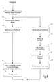
- FIG. 2 shows a flow chart or flow chart
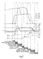
- Fig. 3 shows a graph of speeds and torques and shifts in the powertrain over time.
- a first step (Phase 1 in Fig. 3 and step A1 in Fig. 2 ) first in the first partial transmission 1 (passive partial transmission) from the neutral position as high a gear engaged (grade 3 or 5).
- step A3 the torque of the electric machine is increased to compensate for the drag torque of the internal combustion engine.
- step A2 the cranking or towing of the internal combustion engine can take place by means of the clutch K2. If the drive train has a starter motor 44, however, this turning can also take place by means of the starter motor 44.
- phase 3 of the Fig. 3 the speed of the internal combustion engine has reached the target speed, so that subsequently the clutch K2 can be opened (A4 in FIG Fig. 2 ), and the moment of the electric machine can be shut down. If the starter motor 44 has been used for towing the internal combustion engine, the clutch K2 has not necessarily been closed and consequently does not necessarily have to be reopened.
- step A6 phase 4 in FIG Fig. 3
- step A8 the speed of the electric machine 40
- target gear change gear can be engaged (in phase 6 of Fig. 3 and step A9, target gear is gear 4).
- the torque of the electric machine 40 can in turn be increased to a target torque (phase 7 in FIG Fig. 3 and step A10).
- a preselection gear can already be engaged.
- the procedure of Fig. 2 is therefore based on providing a filling moment by not firing the internal combustion engine, but first towing it so that its momentum energy can be used to provide a filling moment.
- This is in contrast to the procedures of the document DE 10 2010 044 618 A1 a relatively high gear engaged (in this case, the gear 3 or 5 and not the gear 1), which is the second highest or highest gear.
- the torque to be provided by the electric motor 40 for compensation of the drag torque may be lower, so that more torque can be provided in the phases 1 and 2 as well as partly 3 for the drive of the motor vehicle.
- a higher torque can generally be provided by the electric machine for driving the motor vehicle during these phases.
- FIG. 4 and 5 Another embodiment of a method according to the invention is in the Fig. 4 and 5 shown.
- a filling torque is provided by the electric machine 40, wherein this filling torque is guided via the second friction clutch 20 and the first friction clutch 30 on the first power transmission path 36.
- the drive motor 12 is forcibly dragged, so that this Mitschleppmoment must also be compensated.
- the method initially starts with the engagement of a higher gear stage (eg gear stage 5) in the partial transmission 1 (step B1 in FIG Fig. 4 , Phase 1 in Fig. 5 ).
- a higher gear stage eg gear stage 5
- the torque of the electric machine is increased in this phase.
- the second friction clutch 20 (K2) is ramped closed so that the electric machine 40 transfers torque via the second friction clutch 20 and the first friction clutch 30 into the first power transmission path 36. In this case, therefore, the moment of the electric machine 40 is adapted.
- the Fig. 4 (Phases 4 to 6 in Fig. 5 ) the gear change from the starting gear (G2) in the target gear (G4) of the partial transmission 2 done.
- the first friction clutch 30 can then be opened (step B12 in FIG Fig. 4 ), and in parallel, the torque of the electric machine 40 is guided to a target torque (step B13).
- step B14 a target gear stage can be engaged in the first partial transmission, or else a change to a neutral position can take place, as in phase 9 of FIG Fig. 5 shown.
- a further embodiment of a method according to the invention is shown, in which the drive motor is designed as an internal combustion engine and this is not only towed, but also ignited to provide a filling torque by means of the ignited internal combustion engine.
- step C1 a higher gear stage is engaged in the first partial transmission 32 (G3 in phase 1 of FIG Fig. 7 ).
- the second friction clutch K2 is closed so that the internal combustion engine is pulled up (phase 2 in FIG Fig. 7 and step C2 in Fig. 6 ).
- the torque of the electric machine 40 is increased to compensate for the drag torque of the internal combustion engine (step C3).
- the second friction clutch 20 is opened and the first friction clutch 30 is closed. Fill moment is now provided by means of the internal combustion engine via the first power transmission path 36.
- the torque of the electric machine 40 may be shut down (step C5), and the gear shift may be performed in a conventional manner (steps C6 to C8, phases 4 to 6 of FIG Fig. 7 ).
- step C10 the first friction clutch is opened again and in parallel the torque of the electric machine 40 is increased (C9, phase 7 in FIG Fig. 7 ).
- step C11 the internal combustion engine can then be switched off again.
- the duration for which the internal combustion engine is ignited is limited to the time range of the gear change and may in particular be shorter than one second, in particular shorter than half a second.
- FIG. 8 and 9 a further embodiment of a method according to the invention is shown, which essentially corresponds to the method of Fig. 6 and 7 equivalent.
- step D2 the burner is started by means of a starter motor, which is present in this variant in the drive train.
- Step D3 corresponding to step C4 of FIG Fig. 6
- Steps D4 to D7 correspond to steps C5 to C8 of FIG Fig. 6 .
- Steps D9 to D10 correspond to steps C9 to C11 of FIG Fig. 6 .
Abstract
Description
Die vorliegende Erfindung betrifft Verfahren zum Ansteuern eines Hybridantriebsstranges, der einen Antriebsmotor und ein Doppelkupplungsgetriebe aufweist, das zur Einrichtung von zwei Leistungsübertragungspfaden eine erste und eine zweite Reibkupplung und ein erstes und ein zweites Teilgetriebe aufweist, wobei eine elektrische Maschine in Leistungsflussrichtung hinter der zweiten Reibkupplung an dem zweiten Leistungsübertragungspfad angebunden oder anbindbar ist, wobei ein rein elektrischer Fahrbetrieb über das der zweiten Reibkupplung zugeordnete zweite Teilgetriebe erfolgen kann, und wobei bei einem Gangwechsel in dem zweiten Teilgetriebe während eines rein elektrischen Fahrbetriebes ein Füllmoment bereitgestellt wird.The present invention relates to methods of driving a hybrid powertrain having a drive motor and a dual-clutch transmission having a first and a second friction clutch and a first and a second partial transmission for establishing two power transmission paths, wherein an electric machine in the power flow direction behind the second friction clutch the second power transmission path is connected or attachable, wherein a purely electric driving operation via the second friction clutch associated second partial transmission can take place, and wherein during a gear change in the second partial transmission during a purely electric driving operation, a filling torque is provided.
Doppelkupplungsgetriebe der beschriebenen Art sind allgemein bekannt. Durch das Bereitstellen von zwei Leistungsübertragungspfaden ist es möglich, Gangwechsel ohne Zugkrafteinbruch durchzuführen. Dabei wird das von dem Antriebsmotor bereitgestellte Antriebsmoment durch überschneidende Betätigung von einem Leistungsübertragungspfad auf den anderen zugkraftunterbrechungsfrei übergeben. Diese Art der Ansteuerung eines Doppelkupplungsgetriebes ist insbesondere bei Antriebssträngen bekannt, deren Antriebsmotor ein Verbrennungsmotor ist.Dual clutch transmissions of the type described are well known. By providing two power transmission paths, it is possible to perform gear changes without pulling force. In this case, the drive torque provided by the drive motor is transferred by intersecting operation of a power transmission path to the other traction interruption free. This type of control of a dual-clutch transmission is known in particular in drive trains whose drive motor is an internal combustion engine.
Ferner ist es bekannt, Antriebsstränge für Kraftfahrzeuge zu hybridisieren. Dies beinhaltet generell die Bereitstellung wenigstens einer elektrischen Maschine, die in der Regel als elektrischer Motor oder als elektrischer Generator arbeiten kann. In dem Betriebsmodus als elektrische Maschine kann zusätzliches Antriebsmoment bereitgestellt werden. In dem Betriebsmodus als elektrischer Generator kann die elektrische Maschine rekuperierend arbeiten, um beispielsweise bei einem Bremsvorgang elektrische Energie zum Laden eines Energiespeichers zu gewinnen.Furthermore, it is known to hybridize drive trains for motor vehicles. This generally involves the provision of at least one electrical machine, which can usually operate as an electric motor or as an electric generator. In the operating mode as an electric machine, additional drive torque can be provided. In the operating mode as an electrical generator, the electric machine can work recuperating in order, for example, to obtain electrical energy for charging an energy store during a braking operation.
Generell ist es in derartigen Antriebssträngen bekannt, eine elektrische Maschine zwischen dem Antriebsmotor und dem Doppelkupplungsgetriebe anzuordnen, also in Leistungsflussrichtung vor den Reibkupplungen des Doppelkupplungsgetriebes.In general, it is known in such drive trains to arrange an electric machine between the drive motor and the dual-clutch transmission, ie in the power flow direction before the friction clutches of the dual-clutch transmission.
Bei dem eingangs genannten Hybridantriebsstrang ist die elektrische Maschine jedoch innerhalb des Doppelkupplungsgetriebes zumindest zeitweise mit einem Eingang von einem der Teilgetriebe verbunden, also in Leistungsflussrichtung hinter der zugeordneten Reibkupplung (vorliegend der zweiten Reibkupplung). Hierdurch liegt ein Summenpunkt von Antriebsmotor und elektrischer Maschine nicht vor dem Eingang des Doppelkupplungsgetriebes sondern im Getriebe. Hierdurch können die Schaltabläufe eines konventionellen Doppelkupplungsgetriebes ergänzt werden.In the hybrid powertrain mentioned above, however, the electric machine is at least temporarily connected within the dual-clutch transmission to an input of one of the partial transmissions, ie in the power flow direction behind the associated friction clutch (in this case the second friction clutch). As a result, a summation point of the drive motor and electric machine is not in front of the input of the dual-clutch transmission but in the transmission. As a result, the switching sequences of a conventional dual-clutch transmission can be supplemented.
Mit einem Antriebsstrang der beschriebenen Art ist ein konventioneller Betrieb möglich, bei dem nur der Antriebsmotor aktiv ist, die elektrische Maschine jedoch nicht an den Antriebsstrang angebunden ist oder mitgeschleppt wird. Ferner ist ein hybridischer Betriebsmodus möglich, bei dem Antriebsleistung sowohl von dem Antriebsmotor als auch von der elektrischen Maschine bereitgestellt wird. Schließlich ist auch ein rein elektrischer Antrieb möglich, bei dem der Verbrennungsmotor abgeschaltet ist (also in der Regel steht). Hierbei sind die Reibkupplungen des Doppelkupplungsgetriebes in der Regel geöffnet, damit der Antriebsmotor (in der Regel ein Verbrennungsmotor) nicht mitgeschleppt werden muss.With a drive train of the type described a conventional operation is possible in which only the drive motor is active, but the electric machine is not connected to the drive train or is dragged. Further, a hybrid mode of operation is possible in the drive power of both the drive motor as also provided by the electric machine. Finally, a purely electric drive is possible in which the internal combustion engine is switched off (that is, usually stands). In this case, the friction clutches of the dual-clutch transmission are usually open, so that the drive motor (usually an internal combustion engine) does not have to be dragged.
Im rein elektrischen Antriebsmodus können die herkömmlichen Schaltabläufe eines Doppelkupplungsgetriebes nicht angewendet werden, da sich die elektrische Maschine auf der Sekundärseite der zugeordneten Reibkupplung befindet.In the purely electric drive mode, the conventional switching sequences of a dual-clutch transmission can not be applied because the electric machine is located on the secondary side of the associated friction clutch.
Aus dem Dokument
In einer ersten Variante wird der Verbrennungsmotor durch Schließen der einen oder der anderen Kupplung angeschleppt, ohne diesen zu zünden. Während des Gangwechsels (Hochschaltung) wird über die andere Kupplung ein Zugkraftunterstützungsmoment bereitgestellt, das die Schwungenergie des dann austrudelnden Verbrennungsmotors nutzt. Dabei kann in dem der anderen Kupplung zugeordneten Teilgetriebe auch ein Gangstufenwechsel erfolgen, um den Verbrennungsmotor mit einer geeigneten Gangstufe anzuschleppen und mit einer anderen Gangstufe das Zugkraftunterstützungsmoment bereit zu stellen.In a first variant, the internal combustion engine is towed by closing one or the other clutch, without igniting it. During the gear change (upshift), a traction assist torque is provided via the other clutch that uses the flywheel energy of the then coasting internal combustion engine. In this case, in the other clutch associated partial transmission and a gear change can be made to tow the engine with a suitable gear and provide the Zugkraftunterstützungsmoment with another gear.
In einer zweiten Variante kann über vergleichbare Schritte bei Rückschaltungen ein Schubkraftunterstützungsmoment bereit gestellt werden, wobei der Verbrennungsmotor dabei nicht hochgeschleppt wird, sondern im Stillstand als Schlepplast verwendet wird. Dabei ist das Schubkraftunterstützungsmoment so einzuregeln, dass der Verbrennungsmotor nicht in Drehung versetzt wird, also ein auf den Verbrennungsmotor ausgeübtes Drehmoment unterhalb eines sogenannten Losbrechmomentes bleibt.In a second variant, a thrust assistance torque can be provided via comparable steps in downshifts, the internal combustion engine is not dragged up, but is used at a standstill as towing load. In this case, the thrust assistance torque is adjusted so that the internal combustion engine is not rotated, so a force exerted on the engine torque below a so-called breakaway torque remains.
Vor diesem Hintergrund ist es eine Aufgabe der Erfindung, verbesserte Verfahren zum Ansteuern eines Hybrid-Antriebsstranges anzugeben, bei dem eine elektrische Maschine hinter einer Kupplung eines Doppelkupplungsgetriebes angebunden ist.Against this background, it is an object of the invention to provide improved methods for driving a hybrid drive train in which an electric machine is connected behind a clutch of a dual-clutch transmission.
Bei dem eingangs genannten Verfahren wird die obige Aufgabe gemäß einem Aspekt der Erfindung dadurch gelöst, dass das Füllmoment aus der Schwungenergie des zuvor angeschleppten, nicht gezündeten Antriebsmotors bereitgestellt wird, wobei der Antriebsstrang ferner einen elektrischen Anlassermotor aufweist und wobei der Anlassermotor dazu verwendet wird, um den Antriebsmotor anzuschleppen.In the method mentioned above, the above object is achieved according to an aspect of the invention in that the filling torque is provided from the flywheel energy of the previously towed, not ignited drive motor, wherein the drive train further comprises an electric starter motor and wherein the starter motor is used to to tow the drive motor.
In herkömmlichen Antriebssträngen mit Verbrennungsmotor ist es bekannt, zum Starten des Verbrennungsmotors einen elektrischen Anlassermotor bereitzustellen, der den Verbrennungsmotor auf eine Drehzahl hochschleppen kann, bei der der Verbrennungsmotor gezündet werden kann (Zünddrehzahl des Verbrennungsmotors).In conventional powertrains with an internal combustion engine, it is known to provide an electric starter motor for starting the internal combustion engine, which can tow the engine up to a speed at which the internal combustion engine can be ignited (ignition speed of the internal combustion engine).
In Hybrid-Antriebssträngen ist man generell bestrebt, diesen Anlassvorgang mittels der als Antriebsmaschine bereitgestellten elektrischen Maschine durchzuführen, um hierdurch den Bauraum und das Gewicht eines Anlassermotors einzusparen. Bei dem Hybridantriebsstrang, auf den sich die vorliegende Erfindung bezieht, ist dies beispielsweise möglich, indem die erste Reibkupplung geöffnet wird und das zweite Teilgetriebe auf neutral geschaltet wird, so dass Antriebsleistung von der elektrischen Maschine über die zweite Reibkupplung dem Verbrennungsmotor zugeführt werden kann, um diesen anzulassen.In hybrid powertrains, it is generally endeavored to carry out this starting process by means of the electric machine provided as the drive machine in order to save the installation space and the weight of a starter motor. In the hybrid powertrain, to which the present invention relates, this is possible, for example, by the first friction clutch is opened and the second part transmission is switched to neutral, so that drive power can be supplied from the electric machine via the second friction clutch to the internal combustion engine to let this.
Bei der vorliegenden Erfindung ist jedoch ein derartiger Anlassermotor, insbesondere in Form eines elektrischen Anlassermotors, zusätzlich zu der elektrischen Maschine vorgesehen, die als Antriebsmaschine dient.However, in the present invention, such a starter motor, particularly in the form of an electric starter motor, is provided in addition to the electric machine serving as a prime mover.
Hierdurch kann der Antriebsmotor mit dem zugeordneten Anlassermotor in größeren Stückzahlen hergestellt werden, da keine Varianten mit und ohne Anlassermotor notwendig sind. Folglich kann eine Variante des Hybridantriebsstranges auch als rein verbrennungsmotorischer Antriebsstrang vorgesehen sein. Mit anderen Worten kann das Bereitstellen eines Hybridantriebsstranges eine Zusatzoption für einen herkömmlichen Antriebsstrang mit Verbrennungsmotor/Anlassermotor darstellen.In this way, the drive motor with the associated starter motor can be produced in larger quantities, since no variants with and without starter motor are necessary. Consequently, a variant of the hybrid powertrain may also be considered be provided purely internal combustion engine powertrain. In other words, providing a hybrid powertrain may be an additional option to a conventional engine / starter motor powertrain.
Der Grundgedanke des Bereitstellens eines Füllmomentes durch Anschleppen des Antriebsmotors (Verbrennungsmotors), ohne diesen zu zünden, um auf diese Weise Schwungenergie zum Bereitstellen eines Füllmomentes bereitzustellen, ist aus dem Dokument
Das Anschleppen des Antriebsmotors bedingt jedoch hierbei komplexe Schaltvorgänge entweder in dem ersten Teilgetriebe und Ansteuerungen der ersten Reibkupplung und/oder das Bereitstellen eines geeigneten elektrischen Momentes durch die elektrische Maschine. Insbesondere dann, wenn diese bereits an ihrer Leistungsgrenze ist, kann die elektrische Maschine das Schleppmoment des Verbrennungsmotors während dessen Anschleppens möglicherweise nicht hinreichend kompensieren.However, the towing of the drive motor in this case requires complex switching operations either in the first partial transmission and controls the first friction clutch and / or providing a suitable electrical torque by the electric machine. In particular, when it is already at its power limit, the electric machine may not sufficiently compensate for the drag torque of the internal combustion engine while it is being towed.
In diesem Fall ist es vorteilhaft, wenn hierzu der Anlassermotor verwendet wird anstelle der elektrischen Maschine.In this case, it is advantageous if, for this purpose, the starter motor is used instead of the electric machine.
Die Aufgabe wird somit vollkommen gelöst.The task is thus completely solved.
Generell ist es möglich, den Anlassermotor dazu zu verwenden, um den Verbrennungsmotor vollständig auf die Drehzahl hochzuschleppen, die erforderlich ist, um die notwendige Schwungenergie aufzubauen, die später in Form eines Füllmomentes bereitgestellt werden soll. Anlassermotoren haben jedoch in der Regel einen begrenzten Drehzahlbereich, so dass hiermit nicht beliebige Drehzahlen erreicht werden können.In general, it is possible to use the starter motor to fully tow the engine up to the speed required to build up the necessary flywheel energy to be provided later in the form of a fill moment. Starter motors, however, usually have a limited speed range, so that hereby not arbitrary speeds can be achieved.
Gemäß einer besonders bevorzugten Variante wird der Anlassermotor folglich (nur) dazu verwendet, um ein Losbrechmoment beim Anschleppen des Antriebsmotors zu überwinden, wobei der Antriebsmotor anschließend über den ersten oder über den zweiten Leistungsübertragungspfad auf eine Zieldrehzahl angeschleppt wird.According to a particularly preferred variant of the starter motor is therefore (only) used to overcome a breakaway torque when towing the drive motor, wherein the drive motor is then towed over the first or the second power transmission path to a target speed.
Beim Anschleppen eines Verbrennungsmotors ist zunächst ein sogenanntes Losbrechmoment zu überwinden, das größer ist als das anschließend aufzubringende Schleppmoment.When towing an internal combustion engine, a so-called breakaway torque must first be overcome, which is greater than the drag torque to be subsequently applied.
Durch Verwendung des Anlassermotors zur Überwindung des Losbrechmomentes kann die elektrische Maschine, die dieses Moment kompensieren soll, um Zugkraftunterbrechungen bzw. Ruckeln zu vermeiden, entlastet werden.By using the starter motor to overcome the breakaway torque, the electric machine, which should compensate for this moment to avoid traction interruptions or jerking, be relieved.
Die elektrische Maschine muss bei diesem Ansteuerungsvorgang folglich nur das Trägheitsmoment, die Verluste und ein Beschleunigungsmoment liefern, so dass mehr Moment an den Abtrieb geleitet werden kann.Consequently, the electric machine only has to deliver the moment of inertia, the losses and an acceleration torque during this activation process, so that more torque can be transmitted to the output.
Gemäß einer weiteren bevorzugten Ausführungsform, die in Verbindung mit dem Oberbegriff des Anspruchs 1 eine eigene Erfindung gemäß einem zweiten Aspekt darstellt, wird das Füllmoment aus der Schwungenergie des zuvor angeschleppten, nicht gezündeten Antriebsmotors bereitgestellt, wobei das Anschleppen über den ersten Leistungsübertragungspfad erfolgt, und wobei vor dem Anschleppen in dem ersten Teilgetriebe eine hohe Gangstufe eingelegt wird, insbesondere die höchste oder die zweithöchste Gangstufe des zweiten Teilgetriebes.According to another preferred embodiment, which in conjunction with the preamble of
Durch das Einlegen einer hohen Gangstufe wird das von der elektrischen Maschine benötigte Moment, das zur Drehmomentkompensation aufgewendet werden sollte, reduziert.By inserting a high gear, the torque required by the electric machine, which should be expended for torque compensation, is reduced.
Generell ist es auch möglich, dieses Verfahren mit der Verwendung des Anlassermotors zu kombinieren. Ferner ist es auch möglich, im ersten Leistungsübertragungspfad einen Gangwechsel durchzuführen, bevor das Füllmoment zur Verfügung gestellt wird.In general, it is also possible to combine this method with the use of the starter motor. Furthermore, it is also possible to perform a gear change in the first power transmission path before the filling torque is made available.
Beispielsweise ist es auch möglich, zunächst in einer hohen Gangstufe das Losbrechmoment zu überwinden, und anschließend im ersten Leistungsübertragungspfad auf eine niedrigere Gangstufe zu wechseln, um den Antriebsmotor auf eine höhere Drehzahl anschleppen zu können. Hierdurch kann die Schwungenergie erhöht werden, so dass mehr Zeit für den Gangwechsel im zweiten Leistungsübertragungspfad zur Verfügung steht, da über einen längeren Zeitraum Füllmoment aus der Schwungenergie bereitgestellt werden kann.For example, it is also possible to first overcome the breakaway torque in a high gear, and then change in the first power transmission path to a lower gear to the drive motor to a be able to tow higher speed. As a result, the flywheel energy can be increased, so that more time is available for the gear change in the second power transmission path, since filling momentum can be provided from the flywheel energy over a longer period of time.
Gemäß einer weiteren bevorzugten Ausführungsform, die in Verbindung mit dem Oberbegriff des Anspruchs 1 eine eigene Erfindung gemäß einem dritten Aspekt darstellt, wird das Füllmoment aus einem Moment der elektrischen Maschine bereitgestellt, wobei sowohl die erste Reibkupplung als auch die zweite Reibkupplung zumindest abschnittsweise und/oder zumindest teilweise geschlossen werden, um Füllmoment der elektrischen Maschine über den ersten Leistungsübertragungspfad zu übertragen, wobei hierbei der Antriebsmotor mitgeschleppt wird.According to a further preferred embodiment, which in conjunction with the preamble of
Der Antriebsmotor wird bei dieser Ausführungsform nicht gezündet. Folglich ist es notwendig, von der elektrischen Maschine ein Moment bereitzustellen, das nicht nur das Füllmoment beinhaltet, sondern auch das notwendige Moment, um den Antriebsmotor mitzuschleppen.The drive motor is not ignited in this embodiment. Consequently, it is necessary to provide a moment from the electric machine which includes not only the filling moment but also the moment necessary to entrain the drive motor.
Auch diese Ausführungsform kann mit der Variante kombiniert werden, bei der der Anlassermotor zum Überwinden eines Losbrechmomentes verwendet wird.This embodiment can also be combined with the variant in which the starter motor is used to overcome a breakaway torque.
Bei diesem Aspekt der Erfindung ist es bevorzugt, wenn zum Bereitstellen von Füllmoment zuerst die erste Reibkupplung geschlossen wird, vorzugsweise vollständig geschlossen wird, und anschließend die zweite Reibkupplung so weit geschlossen wird, bis über der zweiten Reibkupplung ein Drehmomentgleichgewicht hergestellt ist, so dass ein Startgang in dem zweiten Teilgetriebe ausgelegt werden kann.In this aspect of the invention, it is preferable if, for providing filling moment, first the first friction clutch is closed, preferably completely closed, and then the second friction clutch is closed until a torque equilibrium is established above the second friction clutch, so that a starting gear can be designed in the second partial transmission.
Nach dem Schließen der ersten Reibkupplung überträgt diese das Moment der elektrischen Maschine minus des Schleppmoments des Antriebsmotors. Es versteht sich, dass hierbei in dem ersten Teilgetriebe vorab eine Gangstufe eingelegt werden muss.After closing the first friction clutch transmits the torque of the electric machine minus the drag torque of the drive motor. It is understood that in this case a gear stage must be inserted in advance in the first partial transmission.
Gemäß einem weiteren Aspekt der vorliegenden Erfindung wird die obige Aufgabe gelöst mit einem Verfahren zum Ansteuern eines Hybridantriebsstranges der eingangs genannten Art gemäß dem Oberbegriff des Anspruchs 1, wobei ein Füllmoment bereitgestellt wird aus einem Antriebsmoment des für den Gangwechsel kurzzeitig gezündeten Antriebsmotors.According to a further aspect of the present invention, the above object is achieved with a method for driving a hybrid drive train of the type mentioned according to the preamble of
Bei diesem Aspekt der Erfindung wird der Antriebsmotor folglich nicht angeschleppt, ohne diesen zu zünden, um damit Schwungenergie aufzubauen. Vielmehr wird der Antriebsmotor, der in diesem Fall als Verbrennungsmotor ausgebildet ist, auf eine Drehzahl oberhalb der Zünddrehzahl angeschleppt und anschließend gezündet, so dass der Verbrennungsmotor verbrennungsmotorisches Antriebsmoment bereitstellen kann, das als Füllmoment verwendet wird. Sofort nach Beendigung des Gangwechsels wird der Antriebsmotor dabei wieder abgeschaltet.Thus, in this aspect of the invention, the drive motor is not dragged without igniting it to build up flywheel energy. Rather, the drive motor, which is designed in this case as an internal combustion engine, is towed to a speed above the ignition speed and then ignited, so that the internal combustion engine can provide combustion engine drive torque, which is used as a filling torque. Immediately after completion of the gear change, the drive motor is turned off again.
Dabei ist es von besonderem Vorzug, wenn der Antriebsmotor zunächst durch Schließen der ersten oder der zweiten Reibkupplung hochgeschleppt und gezündet wird, wobei das Füllmoment anschließend über den ersten Leistungsübertragungspfad bereitgestellt wird.It is of particular advantage when the drive motor is first pulled up and ignited by closing the first or the second friction clutch, wherein the filling torque is then provided via the first power transmission path.
Bevorzugt ist es dabei, wenn das Hochschleppen über ein Schließen der zweiten Reibkupplung erfolgt, so dass das hierfür erforderliche Moment der elektrischen Maschine direkt aus dem zweiten Leistungsübertragungspfad bereitgestellt werden kann.It is preferred in this case if the lugging takes place via a closing of the second friction clutch, so that the torque of the electric machine required for this purpose can be provided directly from the second power transmission path.
Gemäß einer weiteren bevorzugten Ausführungsform wird hierbei die zweite Reibkupplung vor dem Auslegen eines Startganges geöffnet, wobei dies vorzugsweise synchronisiert mit einem Herunterfahren des Drehmomentes der elektrischen Maschine auf null erfolgt.According to a further preferred embodiment, in this case the second friction clutch is opened before laying out a starting gear, wherein this is preferably synchronized with a shutdown of the torque of the electric machine to zero.
Gemäß einer weiteren bevorzugten Ausführungsform dieses Aspektes wird das von der elektrischen Maschine bereitgestellte Drehmoment kurzzeitig erhöht, um zunächst ein Losbrechmoment des stillstehenden Antriebsmotors zu überwinden.According to a further preferred embodiment of this aspect, the torque provided by the electric machine is briefly increased to first overcome a breakaway torque of the stationary drive motor.
Vorzugsweise kann die elektrische Maschine dann auch weiterhin verwendet werden, um den Antriebsmotor auf eine Zünddrehzahl anzuschleppen.Preferably, the electric machine can then continue to be used to tow the drive motor to an ignition speed.
Gemäß einer weiteren bevorzugten Ausführungsform weist der Antriebsstrang ferner einen elektrischen Anlassermotor auf, wobei der Anlassermotor zumindest zum Überwinden eines Losbrechmomentes des stillstehenden Antriebsmotors verwendet wird.According to a further preferred embodiment, the drive train further comprises an electric starter motor, wherein the starter motor is used at least for overcoming a breakaway torque of the stationary drive motor.
Bevorzugt ist es, wenn der Anlassermotor auch dazu verwendet wird, um den Verbrennungsmotor auf die Zünddrehzahl anzuschleppen.It is preferred if the starter motor is also used to tow the engine to the ignition speed.
Generell können die obengenannten Verfahren dazu verwendet werden, um ein Füllmoment in Form eines Zugkraftunterstützungsmomentes bei einer Zughochschaltung bereitzustellen.In general, the above-mentioned methods can be used to provide a filling moment in the form of a traction assist torque in a pull upshift.
In gleicher Weise ist es mit den obigen Verfahren möglich, ein Füllmoment in Form eines Zugkraftunterstützungsmomentes bei einer Zugrückschaltung bereitzustellen.Likewise, with the above methods, it is possible to provide a filling torque in the form of a traction assisting torque at a traction downshift.
Generell kann mit den erfindungsgemäßen Verfahren ein Gangwechsel im rein elektrischen Fahrbetrieb erfolgen, wobei zumindest die Qualität von gestützten Gangwechseln mit automatisierten Schaltgetrieben erreicht wird. Die Gesamtschaltzeit für einen solchen Gangwechsel ist vorzugsweise vergleichbar zu jener einer herkömmlichen Schaltung eines Doppelkupplungsgetriebes (mit Momentenübergabe von einem Leistungsübertragungspfad auf den anderen).In general, with the method according to the invention, a gear change can take place in purely electrical driving operation, with at least the quality of supported gear changes being achieved with automated manual transmissions. The total shift time for such a gear change is preferably comparable to that of a conventional shift of a dual-clutch transmission (with torque transfer from one power transmission path to the other).
Insgesamt ergeben sich mit einem derartigen Hybridantriebsstrang bessere Beschleunigungswerte, ein erhöhter Komfort und eine erhöhte Dynamik. Durch das länger anstehende höhere Moment am Abtrieb werden subjektiv kürzere Schaltzeiten erreicht.Overall, with such a hybrid powertrain better acceleration values, increased comfort and increased dynamics. Due to the longer upcoming higher torque at the output subjectively shorter switching times are achieved.
Es versteht sich, dass die vorstehend genannten und die nachstehend noch zu erläuternden Merkmale nicht nur in der jeweils angegebenen Kombination, sondern auch in anderen Kombinationen oder in Alleinstellung verwendbar sind, ohne den Rahmen der vorliegenden Erfindung zu verlassen.It is understood that the features mentioned above and those yet to be explained below can be used not only in the particular combination given, but also in other combinations or in isolation, without departing from the scope of the present invention.
Ausführungsbeispiele der Erfindung sind in der Zeichnung dargestellt und werden in der nachfolgenden Beschreibung näher erläutert. Es zeigen:
- Fig. 1
- eine schematische Darstellung einer ersten Ausführungsform eines Hybridantriebsstranges zur Durchführung des erfindungsgemäßen Verfahrens;
- Fig. 2
- ein Flussdiagramm einer Ausführungsform eines Gangwechsels im rein elektrischen Antriebsmodus mit Zugkraftunterstützung;
- Fig. 3
- ein Zeitablaufdiagramm von Drehzahlen und Drehmomenten zur Erläuterung des Gangwechsels der
Fig. 2 ; - Fig. 4
- ein Flussdiagramm einer weiteren Ausführungsform eines Gangwechsels im rein elektrischen Antriebsmodus mit Zugkraftunterstützung;
- Fig. 5
- ein Zeitablaufdiagramm von Drehzahlen und Drehmomenten zur Erläuterung des Gangwechsels der
Fig. 4 ; - Fig. 6
- ein Flussdiagramm einer weiteren Ausführungsform eines Gangwechsels im rein elektrischen Antriebsmodus mit Zugkraftunterstützung;
- Fig. 7
- ein Zeitablaufdiagramm von Drehzahlen und Drehmomenten zur Erläuterung des Gangwechsels der
Fig. 6 ; - Fig. 8
- ein Flussdiagramm einer weiteren Ausführungsform eines Gangwechsels im rein elektrischen Antriebsmodus mit Zugkraftunterstützung; und
- Fig. 9
- ein Zeitablaufdiagramm von Drehzahlen und Drehmomenten zur Erläuterung des Gangwechsels der
Fig. 8 .
- Fig. 1
- a schematic representation of a first embodiment of a hybrid powertrain for carrying out the method according to the invention;
- Fig. 2
- a flowchart of an embodiment of a gear change in pure electric drive mode with traction assistance;
- Fig. 3
- a timing diagram of speeds and torques to explain the gear change of
Fig. 2 ; - Fig. 4
- a flowchart of another embodiment of a gear change in pure electric drive mode with traction assistance;
- Fig. 5
- a timing diagram of speeds and torques to explain the gear change of
Fig. 4 ; - Fig. 6
- a flowchart of another embodiment of a gear change in pure electric drive mode with traction assistance;
- Fig. 7
- a timing diagram of speeds and torques to explain the gear change of
Fig. 6 ; - Fig. 8
- a flowchart of another embodiment of a gear change in pure electric drive mode with traction assistance; and
- Fig. 9
- a timing diagram of speeds and torques to explain the gear change of
Fig. 8 ,
In
Der Antriebsstrang 10 beinhaltet einen Antriebsmotor 12, beispielsweise in Form eines Verbrennungsmotors, der aus einem Energiespeicher wie einem Kraftstofftank13 versorgt wird. Ferner beinhaltet der Antriebsstrang 10 ein Doppelkupplungsgetriebe (DKG) 14, dessen Abtriebsseite mit einem Differential 16 verbunden ist. Das Differential 16 verteilt Antriebsleistung auf ein linkes und ein rechtes angetriebenes Rad 18L, 18R.The
Das Doppelkupplungsgetriebe 14 beinhaltet eine erste Reibkupplung 30 sowie ein erstes Teilgetriebe 32. Das erste Teilgetriebe 32 beinhaltet beispielsweise die ungeraden Gangstufen 1, 3, 5, etc., die mittels zugeordneter Schaltkupplungen 34 ein- und auslegbar sind. Die erste Reibkupplung 30 (K1) und das erste Teilgetriebe 32 (TG1) bilden einen ersten Leistungsübertragungspfad 36 zur Übertragung von Antriebsleistung von dem Antriebsmotor 12 zu dem Differential 16.The dual-
Das Doppelkupplungsgetriebe 14 beinhaltet ferner eine zweite Reibkupplung 20 (K2) sowie ein zweites Teilgetriebe 22 (TG2). Das zweite Teilgetriebe 22 beinhaltet beispielsweise Gangstufen 2, 4, 6, R, die mittels schematisch angedeuteter Schaltkupplungen 24 ein- und auslegbar sind. Die zweite Reibkupplung 20 und das zweite Teilgetriebe 22 bilden einen zweiten Leistungsübertragungspfad 26 zur Übertragung von Leistung von dem Antriebsmotor 12 zu dem Differential 16.The dual-
Ferner beinhaltet der Antriebsstrang 10 eine elektrische Maschine (EM) 40, die mit einer Anordnung 42 zur Ansteuerung und Energieversorgung verbunden ist. Die Anordnung 42 kann beispielsweise eine Leistungselektronik sowie eine Batterie beinhalten.Further, the
Die elektrische Maschine 40 ist an einen Eingang des zweiten Teilgetriebes 22 fest angebunden, beispielsweise mittels eines Stirnradsatzes oder dergleichen. Alternativ hierzu kann die elektrische Maschine 40 mittels einer Koppelanordnung 46 (beispielsweise in Form einer Schaltkupplung) an den Eingang des zweiten Teilgetriebes 22 angebunden sein.The
In einer alternativen, nicht dargestellten Variante kann die elektrische Maschine 14 auch alternativ an den Eingang des ersten Teilgetriebes 32 angebunden werden, wozu eine geeignete Koppeleinrichtung vorgesehen werden kann.In an alternative, not shown variant, the
Die Anbindung der elektrischen Maschine 40 an jenes Teilgetriebe, das die höchste Gangstufe und die Rückwärtsgangstufe aufweist, ermöglicht ein elektrisches Fahren in nahezu allen Betriebssituationen, wie nachstehend noch ergänzend erläutert werden wird.The connection of the
Der Antriebsstrang 10 ist dazu ausgelegt, in drei unterschiedlichen Betriebsarten zu arbeiten. In einem konventionellen Antriebsmodus wird Antriebsleistung nur von dem Antriebsmotor 12 (Verbrennungsmotor, VM) erzeugt. Gangwechsel erfolgen auf zugkraftunterbrechungsfreie Art und Weise, indem Antriebsleistung über einen der Leistungsübertragungspfade 26, 36 geführt wird, wobei in dem Teilgetriebe des anderen Leistungsübertragungspfades eine Gangstufe vorgewählt wird. Anschließend erfolgt ein Gangwechsel durch Übergabe des Leistungsübertragungsflusses von dem einen Pfad auf den anderen Pfad, indem die Reibkupplungen 20, 30 auf überschneidende Art und Weise betätigt werden. Dieser Antriebsmodus ist auf dem Gebiet der Doppelkupplungsgetriebe allgemein bekannt.The
Ferner ist ein zweiter hybridischer Antriebsmodus einrichtbar, bei dem Antriebsleistung sowohl von dem Antriebsmotor 12 als auch von der elektrischen Maschine 40 bereitgestellt wird. Hierbei können die Antriebsleistungen im Wesentlichen über den Summenpunkt am Eingang des zweiten Teilgetriebes 22 (bzw. in Leistungsflussrichtung hinter der zweiten Reibkupplung 22) aufaddiert werden. Eine weitere Möglichkeit eines hybridischen Antriebsmodus besteht darin, dass Antriebsleistung von der elektrischen Maschine über das eine Teilgetriebe und Antriebsleistung von dem Verbrennungsmotor über das andere Teilgetriebe übertragen werden, wobei ein Summenpunkt dann am Differential liegt. Im zweiten hybridischen Antriebsmodus kann die elektrische Maschine sowohl ein positives als auch ein negatives Drehmoment stellen (Boost-Betrieb bzw. Lastpunktanhebung/Laden).Furthermore, a second hybrid drive mode can be set up, in which drive power is provided by both the
Schließlich ist ein dritter Antriebsmodus möglich, bei dem nur die elektrische Maschine 40 zur Erzeugung von Antriebsleistung angesteuert wird, wohingegen der Antriebsmotor 12 stillgelegt wird. Da die elektrische Maschine 40 auf der Sekundärseite der zweiten Reibkupplung 20 angebunden ist, können in diesem Betriebsmodus die herkömmlichen Schaltabläufe eines Doppelkupplungsgetriebes nicht angewendet werden.Finally, a third drive mode is possible, in which only the
Generell ist es jedoch wünschenswert, im rein elektrischen Vorwärtsfahrbetrieb Gangwechsel von der Vorwärtsgangstufe 2 in die Vorwärtsgangstufe 4, gegebenenfalls in die Vorwärtsgangstufe 6, durchzuführen, und umgekehrt.In general, however, it is desirable, in the purely electric forward driving gear change from the
Im rein elektrischen Fahrbetrieb wird Antriebsleistung von der elektrischen Maschine über das zweite Teilgetriebe 22 dem Differential 16 zugeführt. Die zweite Reibkupplung 20 ist generell geöffnet. Um beispielsweise eine Zughochschaltung durchzuführen, muss das von der elektrischen Maschine 40 bereitgestellte Moment zum Auslegen eines Startganges reduziert werden. Auch während des Einlegens der Zielgangstufe wird von der elektrischen Maschine 40 dabei kein Moment bereitgestellt, da ansonsten gegebenenfalls keine Synchronisierung an der Schaltkupplung 24 erfolgen kann.In purely electrical driving power is supplied from the electric machine via the second
Demzufolge können bei herkömmlichen Hybridantriebssträngen dieser Art Gangwechsel im rein elektrischen Fahrbetrieb nur mit Zugkraftunterbrechung durchgeführt werden.Accordingly, in conventional hybrid powertrains of this type gear changes can be carried out in purely electric driving only with traction interruption.
Um dieses Problem zu lindern, werden nachfolgende Verfahren erläutert.To alleviate this problem, the following procedures are explained.
Sämtliche nachstehend beschriebenen Verfahren gehen davon aus, dass das Fahrzeug im rein elektrischen Betrieb fährt und dass eine automatisierte Schaltung mittels des Antriebsstranges der
Insbesondere gehen die nachstehenden Verfahren davon aus, dass eine Zughochschaltung von der Gangstufe 2 in die Gangstufe 4 stattfindet, wobei diese beiden Gangstufen im zweiten Teilgetriebe 22 (TG2) liegen.In particular, the following procedures assume that an upshift takes place from
In den nachfolgenden Zeitdiagrammen ist bei n_VM die Drehzahl des Verbrennungsmotors gezeigt, bei n_EM die Drehzahl der elektrischen Maschine, bei n_TG1 die Drehzahl am Eingang des ersten Teilgetriebes 32, bei n_TG2 die Drehzahl am Eingang des zweiten Teilgetriebes. Dabei sind die Drehzahlen n_EM und n_TG2 identisch oder proportional, da die elektrische Maschine 40 in diesem Fall fest an den Eingang des zweiten Teilgetriebes 22 (TG2) bzw. an den Ausgang der zweiten Reibkupplung 20 (K2) angekoppelt ist.In the following timing diagrams, the rotational speed of the internal combustion engine is shown at n_VM, the rotational speed of the electric machine at n_EM, the rotational speed at the input of the first
Ferner sind in den nachstehenden Zeitdiagrammen die jeweiligen Drehmomente wie folgt gezeigt: tq_VM ist das Drehmoment des Verbrennungsmotors, tq_EM ist das Drehmoment der elektrischen Maschine, tq_K1 ist das Drehmoment, das von der ersten Reibkupplung 30 (K1) übertragen wird, tq_K2 ist das Drehmoment, das von der zweiten Reibkupplung 20 (K2) übertragen wird.Further, in the timing diagrams below, the respective torques are shown as follows: tq_VM is the torque of the engine, tq_EM is the torque of the electric machine, tq_K1 is the torque transmitted from the first friction clutch 30 (K1), tq_K2 is the torque, which is transmitted from the second friction clutch 20 (K2).
Ferner sind in den Zeitdiagrammen die Gangwechsel gezeigt, wobei diese in den jeweiligen Teilgetrieben TG1, TG2 gezeigt sind, wobei G für Gangstufe steht und wobei N für Neutralstellung steht. Ferner sind die nachstehend beschriebenen Zeitdiagramme hinsichtlich Drehzahl und hinsichtlich Drehmoment teilweise normiert, so dass die unterschiedlichen Übersetzungen herausgerechnet sind, um die Abläufe verständlicher zu machen. Dies gilt insbesondere für das Zeitablaufdiagramm der
Eine erste Ausführungsform eines erfindungsgemäßen Verfahrens ist in den
Bei diesem Verfahren gemäß
In der nachfolgenden Phase 2 der
In
In der Phase 3 der
Durch das Schließen der Kupplung K1 in Phase 3 bis einschließlich Phase 5 der
In dem ersten Leistungsübertragungspfad 36 ist bei geöffneter Kupplung K2 nun im Schritt A6 der Startgang des Gangwechsels auszulegen (Phase 4 in
Anschließend kann, wie bei einem herkömmlichen Gangwechsel, das Moment der elektrischen Maschine 40 wiederum auf ein Zielmoment erhöht werden (Phase 7 in
Das Verfahren der
In der alternativen Variante, bei der der Anlassermotor 44 zum Anschleppen des Verbrennungsmotors verwendet wird, wenigstens jedoch zum Überwinden eines Losbrechmomentes, kann während dieser Phasen generell ein höheres Drehmoment durch die elektrische Maschine für den Antrieb des Kraftfahrzeuges bereitgestellt werden.In the alternative variant, in which the
Eine weitere Ausführungsform eines erfindungsgemäßen Verfahrens ist in den
Bei diesem Verfahren wird ein Füllmoment von der elektrischen Maschine 40 bereitgestellt, wobei dieses Füllmoment über die zweite Reibkupplung 20 und die erste Reibkupplung 30 auf den ersten Leistungsübertragungspfad 36 geführt wird. Hierbei wird der Antriebsmotor 12 zwangsweise mitgeschleppt, so dass dieses Mitschleppmoment ebenfalls mit kompensiert werden muss. Alternativ hierzu ist es denkbar, zwischen den Reibkupplungen 20, 30 eine dritte Reibkupplung vorzusehen, die den Antriebsmotor 12 von dem Doppelkupplungsgetriebe 14 abkoppelt. In diesem Fall muss ein solches Mitschleppmoment nicht überwunden werden, da diese Kupplung in diesem Fall geöffnet werden kann.In this method, a filling torque is provided by the
Das Verfahren startet zunächst mit dem Einlegen einer höheren Gangstufe (z.B. Gangstufe 5) in dem Teilgetriebe 1 (Schritt B1 in
In den nachfolgenden Schritten B2, B3 (Phase 2 in
Zur Kompensation des Schleppmomentes wird in dieser Phase das Drehmoment der elektrischen Maschine erhöht.To compensate for the drag torque, the torque of the electric machine is increased in this phase.
In der anschließenden Phase 3 der
Sobald das Moment über der zweiten Reibkupplung 20 gleich dem von der elektrischen Maschine 40 bereitgestellten Moment ist (in Phase 3 der
Demzufolge kann in den Schritten B7 bis B9 der
In den nachfolgenden Schritten B11, B10 (Phase 7 in
In der Phase 8 kann dann die erste Reibkupplung 30 geöffnet werden (Schritt B12 in
Anschließend kann im Schritt B14 eine Zielgangstufe im ersten Teilgetriebe eingelegt werden, oder aber auch ein Wechsel in eine Neutralstellung erfolgen, wie in der Phase 9 der
In den
Zunächst wird im Schritt C1 in dem ersten Teilgetriebe 32 eine höhere Gangstufe eingelegt (G3 in Phase 1 der
Anschließend wird die zweite Reibkupplung K2 geschlossen, so dass der Verbrennungsmotor hochgeschleppt wird (Phase 2 in
Sobald der Verbrennungsmotor gezündet ist (in Phase 3), wird die zweite Reibkupplung 20 geöffnet und die erste Reibkupplung 30 geschlossen. Über den ersten Leistungsübertragungspfad 36 wird nun Füllmoment mittels des Verbrennungsmotors bereitgestellt. In dem zweiten Leistungsübertragungspfad 26 kann das Moment der elektrischen Maschine 40 heruntergefahren werden (Schritt C5), und der Gangwechsel kann in an sich üblicher Weise erfolgen (Schritte C6 bis C8, Phasen 4 bis 6 der
Anschließend wird im Schritt C10 die erste Reibkupplung wieder geöffnet und parallel hierzu das Moment der elektrischen Maschine 40 erhöht (C9, Phase 7 in
Im Schritt C11 kann der Verbrennungsmotor dann wieder abgeschaltet werden.In step C11, the internal combustion engine can then be switched off again.
Die Dauer, für die der Verbrennungsmotor gezündet wird, ist dabei auf den Zeitbereich des Gangwechsels beschränkt und kann insbesondere kürzer sein als eine Sekunde, insbesondere kürzer als eine halbe Sekunde.The duration for which the internal combustion engine is ignited is limited to the time range of the gear change and may in particular be shorter than one second, in particular shorter than half a second.
In den
Dabei wird der Verbrennungsmotor jedoch nicht durch Schließen der zweiten Reibkupplung hochgedreht, bis er die Zünddrehzahl erreicht hat. Vielmehr wird im Schritt D2 der Verbrenner mittels eines Anlassermotors gestartet, der bei dieser Variante in dem Antriebsstrang vorhanden ist.However, the internal combustion engine is not turned up by closing the second friction clutch until it has reached the ignition speed. Rather, in step D2, the burner is started by means of a starter motor, which is present in this variant in the drive train.
Nach dem Starten kann die Kupplung K1 geschlossen werden (Schritt D3 entsprechend dem Schritt C4 der
Die Schritte D9 bis D10 entsprechen den Schritten C9 bis C11 der
Claims (12)
dadurch gekennzeichnet, dass
das Füllmoment aus der Schwungenergie des zuvor angeschleppten, nicht gezündeten Antriebsmotors (12) bereitgestellt wird, wobei der Antriebsstrang (10) ferner einen elektrischen Anlassermotor (44) aufweist und wobei der Anlassermotor (44) dazu verwendet wird, um den Antriebsmotor (12) anzuschleppen.A method of driving a hybrid powertrain (10) comprising a drive motor (12) and a dual clutch transmission (14) having first and second friction clutches (20, 30) and first and second input means for establishing two power transfer paths (26, 36) second partial transmission (22, 32), wherein an electric machine (40) in the power flow direction behind the second friction clutch (20) is connected to the second power transmission path (26), wherein a purely electric driving over the second friction clutch (20) associated second Partial transmission (22) can take place, and wherein during a gear change in the second partial transmission (22) during a purely electric driving operation, a filling torque is provided,
characterized in that
the charge torque is provided from the flywheel energy of the previously-towed, non-fired drive motor (12), the powertrain (10) further comprising an electric starter motor (44) and wherein the starter motor (44) is used to tow the drive motor (12) ,
Applications Claiming Priority (1)
| Application Number | Priority Date | Filing Date | Title |
|---|---|---|---|
| DE201210018416 DE102012018416B4 (en) | 2012-09-12 | 2012-09-12 | Method for driving a hybrid drive train |
Publications (3)
| Publication Number | Publication Date |
|---|---|
| EP2708400A2 true EP2708400A2 (en) | 2014-03-19 |
| EP2708400A3 EP2708400A3 (en) | 2015-11-11 |
| EP2708400B1 EP2708400B1 (en) | 2021-07-28 |
Family
ID=49035445
Family Applications (1)
| Application Number | Title | Priority Date | Filing Date |
|---|---|---|---|
| EP13181926.0A Active EP2708400B1 (en) | 2012-09-12 | 2013-08-28 | Method for controlling a hybrid power train |
Country Status (4)
| Country | Link |
|---|---|
| US (1) | US9120481B2 (en) |
| EP (1) | EP2708400B1 (en) |
| CN (1) | CN103661362B (en) |
| DE (1) | DE102012018416B4 (en) |
Cited By (2)
| Publication number | Priority date | Publication date | Assignee | Title |
|---|---|---|---|---|
| WO2018087438A1 (en) * | 2016-11-14 | 2018-05-17 | Renault S.A.S | Method and device for controlling a semiautomatic gearbox for a hybrid motor vehicle |
| WO2021063626A1 (en) * | 2019-09-30 | 2021-04-08 | Magna Pt B.V. & Co. Kg | Method for operating a hybrid transmission in the event of a high starting torque requirement and controller |
Families Citing this family (14)
| Publication number | Priority date | Publication date | Assignee | Title |
|---|---|---|---|---|
| KR101637687B1 (en) * | 2014-09-29 | 2016-07-08 | 현대자동차주식회사 | Hybrid transmission for vehicle |
| DE102017100683A1 (en) | 2017-01-16 | 2018-07-19 | GETRAG B.V. & Co. KG | Method for engagement point determination of a friction clutch in a hybrid powertrain |
| US10525970B2 (en) * | 2017-02-24 | 2020-01-07 | Ford Global Technologies, Llc | Systems and methods for controlling an engine start in a hybrid vehicle |
| DE102017104106A1 (en) * | 2017-02-28 | 2018-08-30 | GETRAG B.V. & Co. KG | Method for driving a hybrid drive train |
| DE102017130707A1 (en) | 2017-12-20 | 2019-06-27 | GETRAG B.V. & Co. KG | Method for operating a hybrid drive train and hybrid powertrain for a motor vehicle |
| DE102018208084A1 (en) * | 2018-05-23 | 2019-11-28 | Magna Pt B.V. & Co. Kg | Drive train for a motor vehicle and method for operating the same |
| DE102019100503A1 (en) * | 2019-01-10 | 2020-07-16 | Bayerische Motoren Werke Aktiengesellschaft | Control unit and method for operating a hybrid drive with a double clutch transmission |
| DE102020202141A1 (en) | 2020-02-19 | 2021-08-19 | Magna Pt B.V. & Co. Kg | Double clutch system and method for operating one |
| DE102020202139B4 (en) | 2020-02-19 | 2022-04-14 | Magna Pt B.V. & Co. Kg | Hybrid drive train for a motor vehicle with a separator |
| DE102020202150B4 (en) | 2020-02-19 | 2022-04-14 | Magna Pt B.V. & Co. Kg | Method for operating a hybrid drive train for a motor vehicle with hydraulic actuation for a separating element |
| DE102020202138B4 (en) | 2020-02-19 | 2022-03-31 | Magna Pt B.V. & Co. Kg | Hybrid drive train for a motor vehicle with a separator |
| DE102020206020A1 (en) | 2020-05-13 | 2021-11-18 | Magna Pt B.V. & Co. Kg | Method for controlling a hybrid drive train |
| DE102020209763B4 (en) | 2020-08-03 | 2023-02-09 | Magna Pt B.V. & Co. Kg | Hybrid drive train for a motor vehicle and method for starting |
| CN112721905B (en) * | 2021-01-07 | 2022-04-08 | 浙江吉利控股集团有限公司 | Starting method and device of engine in dual-motor hybrid power system and vehicle |
Citations (1)
| Publication number | Priority date | Publication date | Assignee | Title |
|---|---|---|---|---|
| DE102010044618A1 (en) | 2010-08-27 | 2012-03-01 | Getrag Getriebe- Und Zahnradfabrik Hermann Hagenmeyer Gmbh & Cie Kg | Method for controlling hybrid drive train during purely electrical drive mode, involves transferring filling moment through active power transmission path or passive power transmission path during gear change by purely electric drive |
Family Cites Families (15)
| Publication number | Priority date | Publication date | Assignee | Title |
|---|---|---|---|---|
| EP1714817A1 (en) * | 2005-04-19 | 2006-10-25 | Getrag Ford Transmissions GmbH | Hybrid drive system with double clutch |
| DE102005048938A1 (en) * | 2005-10-13 | 2007-04-19 | Volkswagen Ag | Dual clutch transmission for a motor vehicle, in particular with a hybrid drive or method for controlling this dual clutch transmission |
| JP4961192B2 (en) * | 2006-11-09 | 2012-06-27 | アイシン精機株式会社 | Vehicle drive source control device |
| US8170764B2 (en) * | 2007-11-02 | 2012-05-01 | GM Global Technology Operations LLC | Method and apparatus to reprofile input speed during speed during speed phase during constrained conditions for a hybrid powertrain system |
| DE102008027658A1 (en) * | 2008-06-10 | 2009-12-17 | Bayerische Motoren Werke Aktiengesellschaft | Method for starting internal combustion engine of hybrid vehicle, involves starting internal combustion engine from drove operation mode, in which internal combustion engine is deactivated and is decoupled by coupling device |
| US8137236B2 (en) * | 2008-06-27 | 2012-03-20 | Ford Global Technologies, Llc | Ouput torque modulation control of a transmission in a hybrid electric vehicle |
| DE102008041565A1 (en) * | 2008-08-26 | 2010-03-04 | Robert Bosch Gmbh | Method for operating a hybrid drive device of a motor vehicle and hybrid drive device and electronic control unit |
| DE102009002176B4 (en) * | 2009-04-03 | 2017-07-20 | Robert Bosch Gmbh | Method and device for operating a hybrid vehicle |
| KR20120107468A (en) * | 2009-10-20 | 2012-10-02 | 리카도 유케이 리미티드 | Energy control |
| GB0918384D0 (en) * | 2009-10-20 | 2009-12-02 | Ricardo Uk Ltd | A dual-mode battery |
| GB0918380D0 (en) * | 2009-10-20 | 2009-12-02 | Ricardo Uk Ltd | Torque fill-in |
| GB2476109A (en) * | 2009-12-14 | 2011-06-15 | Gm Global Tech Operations Inc | Hybrid vehicle which uses electric motor to smooth gear changes |
| DE102010030569A1 (en) * | 2010-06-28 | 2011-12-29 | Zf Friedrichshafen Ag | Hybrid drive of a motor vehicle and method for its control |
| KR101521761B1 (en) * | 2011-08-09 | 2015-05-19 | 도요타지도샤가부시키가이샤 | Hybrid vehicle control device |
| US8777789B2 (en) * | 2012-01-04 | 2014-07-15 | Zf Friedrichshafen Ag | Split axis transmission hybrid system architecture |
-
2012
- 2012-09-12 DE DE201210018416 patent/DE102012018416B4/en active Active
-
2013
- 2013-08-28 EP EP13181926.0A patent/EP2708400B1/en active Active
- 2013-09-11 US US14/024,487 patent/US9120481B2/en not_active Expired - Fee Related
- 2013-09-12 CN CN201310415093.XA patent/CN103661362B/en active Active
Patent Citations (1)
| Publication number | Priority date | Publication date | Assignee | Title |
|---|---|---|---|---|
| DE102010044618A1 (en) | 2010-08-27 | 2012-03-01 | Getrag Getriebe- Und Zahnradfabrik Hermann Hagenmeyer Gmbh & Cie Kg | Method for controlling hybrid drive train during purely electrical drive mode, involves transferring filling moment through active power transmission path or passive power transmission path during gear change by purely electric drive |
Cited By (5)
| Publication number | Priority date | Publication date | Assignee | Title |
|---|---|---|---|---|
| WO2018087438A1 (en) * | 2016-11-14 | 2018-05-17 | Renault S.A.S | Method and device for controlling a semiautomatic gearbox for a hybrid motor vehicle |
| FR3058698A1 (en) * | 2016-11-14 | 2018-05-18 | Renault S.A.S | DEVICE FOR CONTROLLING A ROBOTIZED GEARBOX FOR A MOTOR VEHICLE WITH HYBRID PROPULSION |
| KR20190100188A (en) * | 2016-11-14 | 2019-08-28 | 르노 에스.아.에스. | Method and apparatus for controlling semi-automatic gearbox of hybrid motor vehicle |
| CN110312627A (en) * | 2016-11-14 | 2019-10-08 | 雷诺股份公司 | Method and apparatus for controlling hybrid moto vehicle semiautomatic gearbox |
| WO2021063626A1 (en) * | 2019-09-30 | 2021-04-08 | Magna Pt B.V. & Co. Kg | Method for operating a hybrid transmission in the event of a high starting torque requirement and controller |
Also Published As
| Publication number | Publication date |
|---|---|
| DE102012018416A1 (en) | 2014-03-13 |
| CN103661362B (en) | 2018-02-16 |
| EP2708400B1 (en) | 2021-07-28 |
| DE102012018416B4 (en) | 2015-04-23 |
| US20140073480A1 (en) | 2014-03-13 |
| EP2708400A3 (en) | 2015-11-11 |
| US9120481B2 (en) | 2015-09-01 |
| CN103661362A (en) | 2014-03-26 |
Similar Documents
| Publication | Publication Date | Title |
|---|---|---|
| DE102012018416B4 (en) | Method for driving a hybrid drive train | |
| DE102010044618B4 (en) | Method for driving a hybrid drive train | |
| EP2765338B1 (en) | Method for operating a hybrid double clutch transmission drive train | |
| EP2655111B1 (en) | Device for a drivetrain of a hybrid vehicle, drivetrain, and method for operating same | |
| EP2511147B1 (en) | Method for operating a hybrid drive train | |
| EP2794317B1 (en) | Hybrid drive of a motor vehicle and method for operating same | |
| DE102008025516A1 (en) | Control of double-stage switching in a hybrid vehicle | |
| WO2017060010A1 (en) | Method and device for operating a drive device, drive device | |
| EP2757005A2 (en) | Method for holding hill holding a motor vehicle | |
| DE102017216984A1 (en) | Method for controlling a stepped transmission and a drive train, and control device and drive train | |
| DE102020203803A1 (en) | Hybrid transmission with electric traction assistance | |
| DE102017214121A1 (en) | Method for controlling a drive train for a motor vehicle and control device | |
| EP3797231B1 (en) | Drive train for a motor vehicle and method for operating the drive train | |
| WO2021228665A1 (en) | Method for controlling a hybrid drivetrain | |
| DE102022201154A1 (en) | Three-speed hybrid transmission | |
| DE102022202381A1 (en) | Three-speed hybrid transmission | |
| WO2020249307A1 (en) | Transmission for a hybrid drive assembly, hybrid drive assembly, vehicle and method for operating the hybrid drive assembly | |
| DE102022202924A1 (en) | Hybrid transmission | |
| DE102022202919A1 (en) | Compact hybrid transmission | |
| DE102020203179A1 (en) | Hybrid transmission with electric traction assistance | |
| WO2020249337A1 (en) | Transmission for a hybrid drive arrangement, hybrid drive arrangement, vehicle, and method for operating the hybrid drive arrangement | |
| WO2022128216A1 (en) | Switching strategy for hybrid drive train with electric axle | |
| DE102022201151A1 (en) | Compact hybrid transmission | |
| WO2020249336A1 (en) | Transmission for a hybrid drive arrangement, hybrid drive arrangement, vehicle, and method for operating the hybrid drive arrangement | |
| DE102020203773A1 (en) | Multi-gear planetary gear |
Legal Events
| Date | Code | Title | Description |
|---|---|---|---|
| PUAI | Public reference made under article 153(3) epc to a published international application that has entered the european phase |
Free format text: ORIGINAL CODE: 0009012 |
|
| AK | Designated contracting states |
Kind code of ref document: A2 Designated state(s): AL AT BE BG CH CY CZ DE DK EE ES FI FR GB GR HR HU IE IS IT LI LT LU LV MC MK MT NL NO PL PT RO RS SE SI SK SM TR |
|
| AX | Request for extension of the european patent |
Extension state: BA ME |
|
| PUAL | Search report despatched |
Free format text: ORIGINAL CODE: 0009013 |
|
| AK | Designated contracting states |
Kind code of ref document: A3 Designated state(s): AL AT BE BG CH CY CZ DE DK EE ES FI FR GB GR HR HU IE IS IT LI LT LU LV MC MK MT NL NO PL PT RO RS SE SI SK SM TR |
|
| AX | Request for extension of the european patent |
Extension state: BA ME |
|
| RIC1 | Information provided on ipc code assigned before grant |
Ipc: B60W 10/06 20060101ALI20151007BHEP Ipc: B60W 10/08 20060101ALI20151007BHEP Ipc: B60W 10/113 20120101ALI20151007BHEP Ipc: F02N 11/00 20060101ALI20151007BHEP Ipc: B60W 30/19 20120101ALI20151007BHEP Ipc: B60W 20/00 20060101ALI20151007BHEP Ipc: B60W 30/192 20120101ALI20151007BHEP Ipc: B60K 6/48 20071001AFI20151007BHEP |
|
| 17P | Request for examination filed |
Effective date: 20160510 |
|
| RBV | Designated contracting states (corrected) |
Designated state(s): AL AT BE BG CH CY CZ DE DK EE ES FI FR GB GR HR HU IE IS IT LI LT LU LV MC MK MT NL NO PL PT RO RS SE SI SK SM TR |
|
| STAA | Information on the status of an ep patent application or granted ep patent |
Free format text: STATUS: EXAMINATION IS IN PROGRESS |
|
| 17Q | First examination report despatched |
Effective date: 20170202 |
|
| RAP1 | Party data changed (applicant data changed or rights of an application transferred) |
Owner name: GETRAG B.V. & CO. KG |
|
| STAA | Information on the status of an ep patent application or granted ep patent |
Free format text: STATUS: EXAMINATION IS IN PROGRESS |
|
| RIC1 | Information provided on ipc code assigned before grant |
Ipc: B60W 20/00 20160101ALI20151007BHEP Ipc: B60W 30/192 20120101ALI20151007BHEP Ipc: B60W 10/113 20120101ALI20151007BHEP Ipc: F02N 11/00 20060101ALI20151007BHEP Ipc: B60W 30/19 20120101ALI20151007BHEP Ipc: B60W 10/08 20060101ALI20151007BHEP Ipc: B60K 6/48 20071001AFI20151007BHEP Ipc: B60W 10/06 20060101ALI20151007BHEP |
|
| RAP1 | Party data changed (applicant data changed or rights of an application transferred) |
Owner name: MAGNA PT B.V. & CO. KG |
|
| APBK | Appeal reference recorded |
Free format text: ORIGINAL CODE: EPIDOSNREFNE |
|
| APBN | Date of receipt of notice of appeal recorded |
Free format text: ORIGINAL CODE: EPIDOSNNOA2E |
|
| APBR | Date of receipt of statement of grounds of appeal recorded |
Free format text: ORIGINAL CODE: EPIDOSNNOA3E |
|
| APAF | Appeal reference modified |
Free format text: ORIGINAL CODE: EPIDOSCREFNE |
|
| APBX | Invitation to file observations in appeal sent |
Free format text: ORIGINAL CODE: EPIDOSNOBA2E |
|
| APBZ | Receipt of observations in appeal recorded |
Free format text: ORIGINAL CODE: EPIDOSNOBA4E |
|
| APBT | Appeal procedure closed |
Free format text: ORIGINAL CODE: EPIDOSNNOA9E |
|
| GRAP | Despatch of communication of intention to grant a patent |
Free format text: ORIGINAL CODE: EPIDOSNIGR1 |
|
| STAA | Information on the status of an ep patent application or granted ep patent |
Free format text: STATUS: GRANT OF PATENT IS INTENDED |
|
| INTG | Intention to grant announced |
Effective date: 20210318 |
|
| GRAS | Grant fee paid |
Free format text: ORIGINAL CODE: EPIDOSNIGR3 |
|
| GRAA | (expected) grant |
Free format text: ORIGINAL CODE: 0009210 |
|
| STAA | Information on the status of an ep patent application or granted ep patent |
Free format text: STATUS: THE PATENT HAS BEEN GRANTED |
|
| AK | Designated contracting states |
Kind code of ref document: B1 Designated state(s): AL AT BE BG CH CY CZ DE DK EE ES FI FR GB GR HR HU IE IS IT LI LT LU LV MC MK MT NL NO PL PT RO RS SE SI SK SM TR |
|
| REG | Reference to a national code |
Ref country code: GB Ref legal event code: FG4D Free format text: NOT ENGLISH |
|
| REG | Reference to a national code |
Ref country code: CH Ref legal event code: EP |
|
| REG | Reference to a national code |
Ref country code: AT Ref legal event code: REF Ref document number: 1414423 Country of ref document: AT Kind code of ref document: T Effective date: 20210815 |
|
| REG | Reference to a national code |
Ref country code: IE Ref legal event code: FG4D Free format text: LANGUAGE OF EP DOCUMENT: GERMAN |
|
| REG | Reference to a national code |
Ref country code: DE Ref legal event code: R096 Ref document number: 502013015848 Country of ref document: DE |
|
| REG | Reference to a national code |
Ref country code: LT Ref legal event code: MG9D |
|
| REG | Reference to a national code |
Ref country code: NL Ref legal event code: MP Effective date: 20210728 |
|
| PG25 | Lapsed in a contracting state [announced via postgrant information from national office to epo] |
Ref country code: HR Free format text: LAPSE BECAUSE OF FAILURE TO SUBMIT A TRANSLATION OF THE DESCRIPTION OR TO PAY THE FEE WITHIN THE PRESCRIBED TIME-LIMIT Effective date: 20210728 Ref country code: SE Free format text: LAPSE BECAUSE OF FAILURE TO SUBMIT A TRANSLATION OF THE DESCRIPTION OR TO PAY THE FEE WITHIN THE PRESCRIBED TIME-LIMIT Effective date: 20210728 Ref country code: LT Free format text: LAPSE BECAUSE OF FAILURE TO SUBMIT A TRANSLATION OF THE DESCRIPTION OR TO PAY THE FEE WITHIN THE PRESCRIBED TIME-LIMIT Effective date: 20210728 Ref country code: BG Free format text: LAPSE BECAUSE OF FAILURE TO SUBMIT A TRANSLATION OF THE DESCRIPTION OR TO PAY THE FEE WITHIN THE PRESCRIBED TIME-LIMIT Effective date: 20211028 Ref country code: NL Free format text: LAPSE BECAUSE OF FAILURE TO SUBMIT A TRANSLATION OF THE DESCRIPTION OR TO PAY THE FEE WITHIN THE PRESCRIBED TIME-LIMIT Effective date: 20210728 Ref country code: RS Free format text: LAPSE BECAUSE OF FAILURE TO SUBMIT A TRANSLATION OF THE DESCRIPTION OR TO PAY THE FEE WITHIN THE PRESCRIBED TIME-LIMIT Effective date: 20210728 Ref country code: NO Free format text: LAPSE BECAUSE OF FAILURE TO SUBMIT A TRANSLATION OF THE DESCRIPTION OR TO PAY THE FEE WITHIN THE PRESCRIBED TIME-LIMIT Effective date: 20211028 Ref country code: PT Free format text: LAPSE BECAUSE OF FAILURE TO SUBMIT A TRANSLATION OF THE DESCRIPTION OR TO PAY THE FEE WITHIN THE PRESCRIBED TIME-LIMIT Effective date: 20211129 Ref country code: ES Free format text: LAPSE BECAUSE OF FAILURE TO SUBMIT A TRANSLATION OF THE DESCRIPTION OR TO PAY THE FEE WITHIN THE PRESCRIBED TIME-LIMIT Effective date: 20210728 Ref country code: FI Free format text: LAPSE BECAUSE OF FAILURE TO SUBMIT A TRANSLATION OF THE DESCRIPTION OR TO PAY THE FEE WITHIN THE PRESCRIBED TIME-LIMIT Effective date: 20210728 |
|
| PG25 | Lapsed in a contracting state [announced via postgrant information from national office to epo] |
Ref country code: PL Free format text: LAPSE BECAUSE OF FAILURE TO SUBMIT A TRANSLATION OF THE DESCRIPTION OR TO PAY THE FEE WITHIN THE PRESCRIBED TIME-LIMIT Effective date: 20210728 Ref country code: LV Free format text: LAPSE BECAUSE OF FAILURE TO SUBMIT A TRANSLATION OF THE DESCRIPTION OR TO PAY THE FEE WITHIN THE PRESCRIBED TIME-LIMIT Effective date: 20210728 Ref country code: GR Free format text: LAPSE BECAUSE OF FAILURE TO SUBMIT A TRANSLATION OF THE DESCRIPTION OR TO PAY THE FEE WITHIN THE PRESCRIBED TIME-LIMIT Effective date: 20211029 |
|
| REG | Reference to a national code |
Ref country code: CH Ref legal event code: PL |
|
| PG25 | Lapsed in a contracting state [announced via postgrant information from national office to epo] |
Ref country code: LI Free format text: LAPSE BECAUSE OF NON-PAYMENT OF DUE FEES Effective date: 20210831 Ref country code: DK Free format text: LAPSE BECAUSE OF FAILURE TO SUBMIT A TRANSLATION OF THE DESCRIPTION OR TO PAY THE FEE WITHIN THE PRESCRIBED TIME-LIMIT Effective date: 20210728 Ref country code: CH Free format text: LAPSE BECAUSE OF NON-PAYMENT OF DUE FEES Effective date: 20210831 |
|
| REG | Reference to a national code |
Ref country code: DE Ref legal event code: R097 Ref document number: 502013015848 Country of ref document: DE |
|
| PG25 | Lapsed in a contracting state [announced via postgrant information from national office to epo] |
Ref country code: SM Free format text: LAPSE BECAUSE OF FAILURE TO SUBMIT A TRANSLATION OF THE DESCRIPTION OR TO PAY THE FEE WITHIN THE PRESCRIBED TIME-LIMIT Effective date: 20210728 Ref country code: SK Free format text: LAPSE BECAUSE OF FAILURE TO SUBMIT A TRANSLATION OF THE DESCRIPTION OR TO PAY THE FEE WITHIN THE PRESCRIBED TIME-LIMIT Effective date: 20210728 Ref country code: RO Free format text: LAPSE BECAUSE OF FAILURE TO SUBMIT A TRANSLATION OF THE DESCRIPTION OR TO PAY THE FEE WITHIN THE PRESCRIBED TIME-LIMIT Effective date: 20210728 Ref country code: MC Free format text: LAPSE BECAUSE OF FAILURE TO SUBMIT A TRANSLATION OF THE DESCRIPTION OR TO PAY THE FEE WITHIN THE PRESCRIBED TIME-LIMIT Effective date: 20210728 Ref country code: LU Free format text: LAPSE BECAUSE OF NON-PAYMENT OF DUE FEES Effective date: 20210828 Ref country code: EE Free format text: LAPSE BECAUSE OF FAILURE TO SUBMIT A TRANSLATION OF THE DESCRIPTION OR TO PAY THE FEE WITHIN THE PRESCRIBED TIME-LIMIT Effective date: 20210728 Ref country code: CZ Free format text: LAPSE BECAUSE OF FAILURE TO SUBMIT A TRANSLATION OF THE DESCRIPTION OR TO PAY THE FEE WITHIN THE PRESCRIBED TIME-LIMIT Effective date: 20210728 Ref country code: AL Free format text: LAPSE BECAUSE OF FAILURE TO SUBMIT A TRANSLATION OF THE DESCRIPTION OR TO PAY THE FEE WITHIN THE PRESCRIBED TIME-LIMIT Effective date: 20210728 |
|
| PLBE | No opposition filed within time limit |
Free format text: ORIGINAL CODE: 0009261 |
|
| STAA | Information on the status of an ep patent application or granted ep patent |
Free format text: STATUS: NO OPPOSITION FILED WITHIN TIME LIMIT |
|
| GBPC | Gb: european patent ceased through non-payment of renewal fee |
Effective date: 20211028 |
|
| 26N | No opposition filed |
Effective date: 20220429 |
|
| PG25 | Lapsed in a contracting state [announced via postgrant information from national office to epo] |
Ref country code: IT Free format text: LAPSE BECAUSE OF FAILURE TO SUBMIT A TRANSLATION OF THE DESCRIPTION OR TO PAY THE FEE WITHIN THE PRESCRIBED TIME-LIMIT Effective date: 20210728 Ref country code: IE Free format text: LAPSE BECAUSE OF NON-PAYMENT OF DUE FEES Effective date: 20210828 Ref country code: GB Free format text: LAPSE BECAUSE OF NON-PAYMENT OF DUE FEES Effective date: 20211028 |
|
| REG | Reference to a national code |
Ref country code: AT Ref legal event code: MM01 Ref document number: 1414423 Country of ref document: AT Kind code of ref document: T Effective date: 20210828 |
|
| PG25 | Lapsed in a contracting state [announced via postgrant information from national office to epo] |
Ref country code: AT Free format text: LAPSE BECAUSE OF NON-PAYMENT OF DUE FEES Effective date: 20210828 |
|
| PG25 | Lapsed in a contracting state [announced via postgrant information from national office to epo] |
Ref country code: HU Free format text: LAPSE BECAUSE OF FAILURE TO SUBMIT A TRANSLATION OF THE DESCRIPTION OR TO PAY THE FEE WITHIN THE PRESCRIBED TIME-LIMIT; INVALID AB INITIO Effective date: 20130828 |
|
| PG25 | Lapsed in a contracting state [announced via postgrant information from national office to epo] |
Ref country code: CY Free format text: LAPSE BECAUSE OF FAILURE TO SUBMIT A TRANSLATION OF THE DESCRIPTION OR TO PAY THE FEE WITHIN THE PRESCRIBED TIME-LIMIT Effective date: 20210728 |
|
| PGFP | Annual fee paid to national office [announced via postgrant information from national office to epo] |
Ref country code: FR Payment date: 20230824 Year of fee payment: 11 Ref country code: DE Payment date: 20230821 Year of fee payment: 11 Ref country code: BE Payment date: 20230821 Year of fee payment: 11 |