EP2708317A2 - Dust collecting attachment - Google Patents
Dust collecting attachment Download PDFInfo
- Publication number
- EP2708317A2 EP2708317A2 EP20130193155 EP13193155A EP2708317A2 EP 2708317 A2 EP2708317 A2 EP 2708317A2 EP 20130193155 EP20130193155 EP 20130193155 EP 13193155 A EP13193155 A EP 13193155A EP 2708317 A2 EP2708317 A2 EP 2708317A2
- Authority
- EP
- European Patent Office
- Prior art keywords
- dust collecting
- tool
- bit
- end region
- dust
- Prior art date
- Legal status (The legal status is an assumption and is not a legal conclusion. Google has not performed a legal analysis and makes no representation as to the accuracy of the status listed.)
- Granted
Links
- 239000000428 dust Substances 0.000 title claims abstract description 299
- 239000011347 resin Substances 0.000 claims description 7
- 229920005989 resin Polymers 0.000 claims description 7
- 230000000717 retained effect Effects 0.000 claims description 5
- 238000003780 insertion Methods 0.000 claims description 3
- 230000037431 insertion Effects 0.000 claims description 3
- 238000000034 method Methods 0.000 abstract description 9
- 230000007246 mechanism Effects 0.000 description 37
- 238000010276 construction Methods 0.000 description 23
- 238000005553 drilling Methods 0.000 description 17
- 210000000078 claw Anatomy 0.000 description 15
- 230000002265 prevention Effects 0.000 description 5
- 230000002452 interceptive effect Effects 0.000 description 4
- 238000007789 sealing Methods 0.000 description 4
- 230000008569 process Effects 0.000 description 3
- 230000008859 change Effects 0.000 description 2
- 230000000694 effects Effects 0.000 description 2
- 230000004048 modification Effects 0.000 description 2
- 238000012986 modification Methods 0.000 description 2
- 244000309464 bull Species 0.000 description 1
- 230000008602 contraction Effects 0.000 description 1
- 230000000881 depressing effect Effects 0.000 description 1
- 238000004519 manufacturing process Methods 0.000 description 1
- 239000000203 mixture Substances 0.000 description 1
Images


Classifications
-
- B—PERFORMING OPERATIONS; TRANSPORTING
- B23—MACHINE TOOLS; METAL-WORKING NOT OTHERWISE PROVIDED FOR
- B23Q—DETAILS, COMPONENTS, OR ACCESSORIES FOR MACHINE TOOLS, e.g. ARRANGEMENTS FOR COPYING OR CONTROLLING; MACHINE TOOLS IN GENERAL CHARACTERISED BY THE CONSTRUCTION OF PARTICULAR DETAILS OR COMPONENTS; COMBINATIONS OR ASSOCIATIONS OF METAL-WORKING MACHINES, NOT DIRECTED TO A PARTICULAR RESULT
- B23Q11/00—Accessories fitted to machine tools for keeping tools or parts of the machine in good working condition or for cooling work; Safety devices specially combined with or arranged in, or specially adapted for use in connection with, machine tools
- B23Q11/0042—Devices for removing chips
- B23Q11/0046—Devices for removing chips by sucking
-
- B—PERFORMING OPERATIONS; TRANSPORTING
- B25—HAND TOOLS; PORTABLE POWER-DRIVEN TOOLS; MANIPULATORS
- B25D—PERCUSSIVE TOOLS
- B25D16/00—Portable percussive machines with superimposed rotation, the rotational movement of the output shaft of a motor being modified to generate axial impacts on the tool bit
-
- B—PERFORMING OPERATIONS; TRANSPORTING
- B25—HAND TOOLS; PORTABLE POWER-DRIVEN TOOLS; MANIPULATORS
- B25D—PERCUSSIVE TOOLS
- B25D17/00—Details of, or accessories for, portable power-driven percussive tools
- B25D17/08—Means for retaining and guiding the tool bit, e.g. chucks allowing axial oscillation of the tool bit
- B25D17/084—Rotating chucks or sockets
- B25D17/088—Rotating chucks or sockets with radial movable locking elements co-operating with bit shafts specially adapted therefor
-
- B—PERFORMING OPERATIONS; TRANSPORTING
- B25—HAND TOOLS; PORTABLE POWER-DRIVEN TOOLS; MANIPULATORS
- B25F—COMBINATION OR MULTI-PURPOSE TOOLS NOT OTHERWISE PROVIDED FOR; DETAILS OR COMPONENTS OF PORTABLE POWER-DRIVEN TOOLS NOT PARTICULARLY RELATED TO THE OPERATIONS PERFORMED AND NOT OTHERWISE PROVIDED FOR
- B25F5/00—Details or components of portable power-driven tools not particularly related to the operations performed and not otherwise provided for
- B25F5/02—Construction of casings, bodies or handles
- B25F5/025—Construction of casings, bodies or handles with torque reaction bars for rotary tools
- B25F5/026—Construction of casings, bodies or handles with torque reaction bars for rotary tools in the form of an auxiliary handle
-
- B—PERFORMING OPERATIONS; TRANSPORTING
- B23—MACHINE TOOLS; METAL-WORKING NOT OTHERWISE PROVIDED FOR
- B23B—TURNING; BORING
- B23B2260/00—Details of constructional elements
- B23B2260/058—Dust covers
-
- B—PERFORMING OPERATIONS; TRANSPORTING
- B23—MACHINE TOOLS; METAL-WORKING NOT OTHERWISE PROVIDED FOR
- B23B—TURNING; BORING
- B23B2270/00—Details of turning, boring or drilling machines, processes or tools not otherwise provided for
- B23B2270/30—Chip guiding or removal
-
- B—PERFORMING OPERATIONS; TRANSPORTING
- B23—MACHINE TOOLS; METAL-WORKING NOT OTHERWISE PROVIDED FOR
- B23B—TURNING; BORING
- B23B47/00—Constructional features of components specially designed for boring or drilling machines; Accessories therefor
- B23B47/34—Arrangements for removing chips out of the holes made; Chip- breaking arrangements attached to the tool
-
- B—PERFORMING OPERATIONS; TRANSPORTING
- B23—MACHINE TOOLS; METAL-WORKING NOT OTHERWISE PROVIDED FOR
- B23Q—DETAILS, COMPONENTS, OR ACCESSORIES FOR MACHINE TOOLS, e.g. ARRANGEMENTS FOR COPYING OR CONTROLLING; MACHINE TOOLS IN GENERAL CHARACTERISED BY THE CONSTRUCTION OF PARTICULAR DETAILS OR COMPONENTS; COMBINATIONS OR ASSOCIATIONS OF METAL-WORKING MACHINES, NOT DIRECTED TO A PARTICULAR RESULT
- B23Q11/00—Accessories fitted to machine tools for keeping tools or parts of the machine in good working condition or for cooling work; Safety devices specially combined with or arranged in, or specially adapted for use in connection with, machine tools
- B23Q11/0042—Devices for removing chips
- B23Q11/0071—Devices for removing chips dust collectors for hand tools
-
- B—PERFORMING OPERATIONS; TRANSPORTING
- B25—HAND TOOLS; PORTABLE POWER-DRIVEN TOOLS; MANIPULATORS
- B25D—PERCUSSIVE TOOLS
- B25D2216/00—Details of portable percussive machines with superimposed rotation, the rotational movement of the output shaft of a motor being modified to generate axial impacts on the tool bit
- B25D2216/0007—Details of percussion or rotation modes
- B25D2216/0015—Tools having a percussion-only mode
-
- B—PERFORMING OPERATIONS; TRANSPORTING
- B25—HAND TOOLS; PORTABLE POWER-DRIVEN TOOLS; MANIPULATORS
- B25D—PERCUSSIVE TOOLS
- B25D2216/00—Details of portable percussive machines with superimposed rotation, the rotational movement of the output shaft of a motor being modified to generate axial impacts on the tool bit
- B25D2216/0007—Details of percussion or rotation modes
- B25D2216/0023—Tools having a percussion-and-rotation mode
-
- B—PERFORMING OPERATIONS; TRANSPORTING
- B25—HAND TOOLS; PORTABLE POWER-DRIVEN TOOLS; MANIPULATORS
- B25D—PERCUSSIVE TOOLS
- B25D2216/00—Details of portable percussive machines with superimposed rotation, the rotational movement of the output shaft of a motor being modified to generate axial impacts on the tool bit
- B25D2216/0007—Details of percussion or rotation modes
- B25D2216/0038—Tools having a rotation-only mode
-
- Y—GENERAL TAGGING OF NEW TECHNOLOGICAL DEVELOPMENTS; GENERAL TAGGING OF CROSS-SECTIONAL TECHNOLOGIES SPANNING OVER SEVERAL SECTIONS OF THE IPC; TECHNICAL SUBJECTS COVERED BY FORMER USPC CROSS-REFERENCE ART COLLECTIONS [XRACs] AND DIGESTS
- Y10—TECHNICAL SUBJECTS COVERED BY FORMER USPC
- Y10T—TECHNICAL SUBJECTS COVERED BY FORMER US CLASSIFICATION
- Y10T408/00—Cutting by use of rotating axially moving tool
- Y10T408/44—Cutting by use of rotating axially moving tool with means to apply transient, fluent medium to work or product
-
- Y—GENERAL TAGGING OF NEW TECHNOLOGICAL DEVELOPMENTS; GENERAL TAGGING OF CROSS-SECTIONAL TECHNOLOGIES SPANNING OVER SEVERAL SECTIONS OF THE IPC; TECHNICAL SUBJECTS COVERED BY FORMER USPC CROSS-REFERENCE ART COLLECTIONS [XRACs] AND DIGESTS
- Y10—TECHNICAL SUBJECTS COVERED BY FORMER USPC
- Y10T—TECHNICAL SUBJECTS COVERED BY FORMER US CLASSIFICATION
- Y10T408/00—Cutting by use of rotating axially moving tool
- Y10T408/50—Cutting by use of rotating axially moving tool with product handling or receiving means
Definitions
- the invention relates to a dust collecting attachment for collecting dust generated during operation, which is used on a power tool that performs a predetermined operation on a workpiece by driving a tool bit.
- Japanese patent publication No. 3726437 discloses a dust collecting attachment.
- This known dust collecting attachment is used on a hammer drill in which a hammer bit linearly moves in the axial direction and rotates in the circumferential direction.
- the dust collecting attachment includes a dust collecting cup for collecting dust generated during drilling operation on a workpiece.
- the dust collecting cup is shaped like a bellows and arranged to surround a front end region of the tool body around the longitudinal axis ofthe front end region, and one end of the dust collecting cup in the longitudinal direction is mounted to a side handle of the hammer drill.
- a representative dust collecting attachment which is used on a power tool having a tool body, a tool bit which can be coupled to a front end region of the tool body, and an auxiliary handle attached to the tool body.
- the dust collecting attachment includes a dust collecting member which can be attached to the auxiliary handle in such a manner as to surround the front end region of the tool body around a longitudinal axis of the front end region in order to collect dust generated during operation by the power tool, and a connecting hose for connecting the dust collecting member to a dust collector.
- the "power tool” in the invention typically represents a hammer in which a tool bit performs a hammering operation on a workpiece by linearly moving in the axial direction, or a hammer drill in which a tool bit performs a hammer drill operation on a workpiece by linearly moving in the axial direction and rotating around its axis.
- the auxiliary handle attached to the tool body is a non-rotational member.
- the dust collecting attachment according to this invention can be attached to such a non-rotational auxiliary handle. Therefore, the dust collecting attachment can be used on both the power tool in which the tool bit is caused to perform striking movement in the axial direction and the power tool in which the tool bit is caused to perform striking movement in the axial direction and rotation around its axis.
- the auxiliary handle is a member retrofitted to the tool body. Therefore, with the construction in which the dust collecting attachment is attached to the auxiliary handle, the dust collecting attachment can be applied without making any change or modification to the tool body of the power tool.
- the dust collecting attachment has a connecting hose for connecting the dust collecting member to a dust collector. Therefore, dust generated during operation is collected by the dust collecting member and dust within the dust collecting member can be forcibly sucked by the dust collector. With such a construction, an additional process of disposal of dust accumulated in the dust collecting member, which is required in the construction in which dust is not forcibly collected, can be dispensed with, so that rational dust collection can be realized. Further, it is not necessary to interrupt the operation in order to dispose of the dust collected within the dust collecting member, so that workability can also be improved.
- the dust collecting member may preferably have a protrusion on one end of the dust collecting member in the longitudinal direction, and is attached to the auxiliary handle by insertion of the protrusion into a mounting hole formed in the auxiliary handle.
- the protrusion inserted into the mounting hole may be engaged with a resin spring formed on a wall surface of the mounting hole and thereby retained in an inserted position.
- the "engagement" is preferably provided by the construction in which the protrusion and the resin spring have a concave and a convex, respectively, which are designed to be engaged with each other when the protrusion is inserted to a predetermined position in the mounting hole.
- the protrusion inserted into the mounting hole can be retained by the resin spring, so that the dust collecting member can be prevented from unexpectedly becoming detached from the auxiliary handle, for example, due to vibration caused by operation.
- the resin spring can be integrally formed with a component of the mounting hole, so that manufacturability can be improved.
- two mounting holes and two protrusions may be provided in the circumferential direction of the dust collecting member, and each of the protrusions may preferably be shaped like a cylindrical pin.
- a dust collecting attachment may be provided which is used on a power tool that performs a predetermined operation on a workpiece by a tool bit coupled to a front end region of a tool body.
- the dust collecting attachment may have a dust collecting member for use in a first operation mode in which the tool bit only linearly moves, and this dust collecting member may include a bit surrounding portion that surrounds the tool bit around a longitudinal axis of the front end region of the tool body, and a front end region surrounding portion that surrounds the front end region of the tool body around the longitudinal axis of the front end region.
- the dust collecting attachment further has a dust collecting member for use in a second operation mode in which the tool bit at least rotates, and this dust collecting member includes a bit surrounding portion that surrounds the tool bit around the longitudinal axis of the front end region of the tool body, and a front end region surrounding portion that surrounds the front end region of the tool body around the longitudinal axis of the front end region.
- Each of the dust collecting members for use in the first and second operation modes can be disposed in such a manner as to surround the front end region of the power tool around the longitudinal axis in order to collect dust generated by operation of the power tool, and at least the bit surrounding portions of the dust collecting members can be replaced with each other.
- the dust collecting member for use in operation in the first operation mode (hammering operation) in which the tool bit only linearly moves, or the dust collecting member for use in operation in the second operation mode (drilling operation) in which the tool bit at least rotates can be attached to the front end region of the tool body by replacing the bit surrounding portions with each other or by replacing not only the bit surrounding portions but also the dust collecting members in their entirety including the front end region surrounding portions with each other. Therefore, during operation, dust can be collected by using the dust collecting members each designed to efficiently collect dust in assigned operation mode.
- the dust collecting member having the bit surrounding portion which is conically shaped (trumpet-shaped) such that dust (concrete pieces) easily enter the dust collecting member can be used.
- the dust collecting member having the bit surrounding portion which has an extensible structure such that an operation can be performed with the dust collecting member pressed against a workpiece can be used.
- rational dust collection can be realized by using the dust collecting members suitable for each operation mode.
- the front end region surrounding portions can be rationally shared.
- the dust collecting member for use in the first operation mode may be configured such that an opening area of its front end region in the longitudinal direction is larger than a sectional area of the bit surrounding portion. Further, the first dust collecting member has a region for filling a clearance between an outer circumferential surface of the tool bit and an inner circumferential surface of the dust collecting member in a halfway region in the longitudinal direction. By thus increasing the opening area of the front end region, the dust collecting member can efficiently receive dust.
- the dust collecting member has the region for filling the clearance between the outer circumferential surface of the tool bit and the inner circumferential surface of the dust collecting member in the halfway region in the longitudinal direction, large concrete pieces can be prevented from being sucked to the downstream side and thereby causing clogging of the hose.
- the dust collecting member may have an opening which is located in a position corresponding to an operating member which is provided for removal of the tool bit and/or for bit angle adjustment in the front end region ofthe power tool, and the operating member can be operated by user's fingers through the opening.
- the user can operate the operating member through the opening with the dust collecting member left attached to the power tool, so that workability in removal of the tool bit and/or bit angle adjustment can be improved.
- the "operating member" in the invention typically represents a member which is operated to release the tool bit from the tool holding device in order to remove the tool bit held by the tool holding device, and/or, a member for adjusting the angle of the tool bit held by the tool holding device to a predetermined angle when the power tool performs in hammer mode in which the tool bit is caused to linearly move in its axial direction.
- the dust collecting member may have a fastener for fastening the connecting hose to the tool body of the power tool.
- the connecting hose can be fastened to the tool body along its outer surface.
- the connecting hose is prevented from hanging down and swinging during operation and thus prevented from interfering with the operation.
- the fastener may comprise a band-like member for binding the connecting hose to the tool body.
- the connecting hose can be easily fastened to the tool body.
- the manner of "binding" typically represents tying or strapping, but widely includes other manners such as fastening by a hook-and-loop fastener.
- the connecting hose may be held by a supplementary fixing rib which is formed on the tool body and conforms to an outer circumferential surface of the connecting hose.
- a power tool may be provided which has the dust collecting attachment as defined in any one of claims 1 to 10.
- the power tool can be provided with the dust collecting attachment having an improved dust collecting effect.
- a dust collecting attachment is used on an electric hammer drill which is a representative example of a power tool.
- a hammer drill on which the dust collecting attachment is used is explained.
- a hammer drill 201 mainly includes a body 203 that forms an outer shell of the hammer drill 201, a hammer bit 219 detachably coupled to a tip end region (front end portion) of the body 203 via a tool holding device 204 and a handgrip 209 that is designed as a main handle and disposed on a side (rear end portion) of the body 203 opposite from the hammer bit 219.
- the hammer bit 219 is held by the tool holding device 204 such that it is allowed to move with respect to the tool holding device 204 in its axial direction and prevented from rotating with respect to the tool holding device in its circumferential direction.
- the body 203 and the hammer bit 219 are features that correspond to the "tool body” and the “tool bit”, respectively, according to the invention.
- the side of the hammer bit 219 is taken as the front and the side of the handgrip 209 as the rear.
- the body 203 mainly includes a motor housing 205 that houses a driving motor (not shown), and a gear housing 207 that houses an internal mechanism related to striking movement and rotation of the hammer bit 219.
- the driving motor is disposed such that its rotation axis extends in a direction transverse to the axial direction of the hammer bit 219. Therefore, as shown in FIG. 1 , the body 203 has a generally L-shaped body structure formed by the motor housing 205 and the gear housing 207.
- the handgrip 209 disposed on the rear end of the body 203 is configured as a generally D-shaped handle extending in the vertical direction transverse to the axial direction of the hammer bit 219 and having upper and lower ends connected to the body 203.
- a cylindrical barrel 206 is provided on the front of the gear housing 207 and the side grip 208 is detachably attached to the barrel 206.
- the side grip 208 is a feature that corresponds to the "auxiliary handle” according to the invention. Attachment of the side grip 208 is described below.
- the internal mechanism mainly includes a crank mechanism (not shown) as a motion converting mechanism, a striking mechanism 215 and a power transmitting mechanism (not shown).
- the crank mechanism converts the rotating output of the driving motor into linear motion.
- the striking mechanism 215 linearly moves in the longitudinal direction of the body 203 via components of linear motion of the crank mechanism and thereby strikes the hammer bit 219.
- the power transmitting mechanism appropriately reduces the speed of the rotating output of the driving motor and transmits it to the hammer bit 219 and thereby causes the hammer bit 219 to rotate in the circumferential direction.
- the striking mechanism 215 mainly includes a striking element in the form of a striker 235 that linearly moves, and an intermediate element in the form of an impact bolt 237 that transmits the striking force of the striker 235 to the hammer bit 219 (see FIG. 2 ). Further, a specific structure of causing the hammer bit 219 to perform the striking movement and rotation via the internal mechanism is known and therefore it is not described in further detail.
- the tool holding device 204 mainly includes a cylindrical tool holder 241 with a bit insert hole 241a having a circular section into which the stem of the hammer bit 219 is removably inserted, a removal preventing member in the form of a plurality of engagement claws 243 which prevent removal of the hammer bit 219 inserted into the bit insert hole 241a, and a generally cylindrical tool sleeve 245 that can be operated to release the hammer bit 219 from removal prevention by the engagement claws 243.
- the tool sleeve 245 is disposed in front of the barrel 206 of the gear housing 207 such that it can be moved by the user in the axial direction of the hammer bit 219.
- the tool sleeve 245 is normally biased forward by a biasing spring 249 and retains the engagement claws 243 in the removal preventing position (as shown in the drawing) via a retaining ring 247. When the tool sleeve 245 is slid rearward (toward the handgrip), the bit removal prevention by the engagement claws 243 is released.
- the tool sleeve 245 is a feature that corresponds to the "operation member for removal of the tool bit" according to the invention.
- the rotating output of the driving motor is converted into linear motion via the motion converting mechanism and then transmitted as linear motion in the axial direction to the hammer bit 219 via the striking mechanism.
- the hammer bit 219 perform linear movement (hereinafter also referred to as striking movement).
- rotation is transmitted to the tool holding device 204 via the power transmitting mechanism driven by the rotating output of the driving motor, so that the hammer bit 219 held by the tool holding device 204 is caused to rotate in the circumferential direction.
- the hammer bit 219 performs a hammer drill (drilling) operation on a workpiece (concrete) by striking movement in the axial direction and rotation in the circumferential direction.
- the hammer drill 201 can be switched not only to the hammer drill mode in which the hammer bit 119 is caused to perform striking movement in the axial direction and rotation in the circumferential direction as described above, but to the drill mode in which the hammer bit 119 is caused to perform only rotation, or the hammer mode in which the hammer bit 119 is caused to perform only striking movement.
- This mode switching is a known technique and not directly related to the invention, and therefore its description is omitted.
- the hammer drill 201 constructed as described above generates dust during operation on a workpiece (such as concrete).
- the dust collecting attachment 250 is mounted to the side grip 208. Therefore, the side grip 208 is described before explanation of the dust collecting attachment 250.
- the side grip 208 is mounted to the barrel 206 of the gear housing 207.
- a grip mounting portion 281 is formed on the outer surface of the barrel 206 by a circumferential surface having a predetermined width and extending parallel to the longitudinal direction of the body 203.
- the side grip 208 is configured as a rod-like member extending in a direction transverse to the axial direction of the hammer bit 219 as a whole.
- the side grip 208 mainly includes a band 283 wrapped around the outer surface of the grip mounting portion 281 of the barrel 206, a base 285 having a generally U-shaped engagement surface 285a which is disposed on the end of the band 283 and engaged with the outer surface of the grip mounting portion 281, a grip 287 which is connected to the base 285 and can rotate around its longitudinal axis, and a threaded operation rod 289 for tightening the band 283.
- the operation rod 289 is loosely inserted through the central portions of the grip 287 and the base 285 and extends in the longitudinal direction ofthe grip.
- One end of the operation rod 289 is connected to the end of the band 283 and the other end is threadably engaged with a nut 286 disposed within the grip 287.
- the nut 286 is prevented from rotating with respect to the grip 287. Therefore, by rotating the grip 287 clockwise or counterclockwise around its longitudinal axis, the threaded operation rod 289 threadably engaged with the nut 286 is moved forward or rearward in the longitudinal direction, so that the band 283 can be tightened or loosened.
- the side grip 208 is fixed to the grip mounting portion 281 by tightening the band 283.
- the side grip 208 is mounted to the body 203 and protrudes substantially horizontally in a lateral direction of the body 203.
- the dust collecting attachment 250 is now explained.
- the dust collecting attachment 250 according to this embodiment is designed for drilling operation in which the hammer bit 219 is driven in hammer drill mode or drill mode.
- the dust collecting attachment 250 mainly includes a dust collecting cup 251 which has a cylindrical shape having both ends open and covers the front end region of the body 203 including the hammer bit 219, and a connecting hose 273 which connects the dust collecting cup 251 to a dust collector.
- the dust collecting cup 251 is a feature that corresponds to the "dust collecting member" according to the invention.
- the dust collecting cup 251 includes an extensible bellows cup body 253, and a cylindrical cup mounting portion 255 which is connected to one end (rear end) of the cup body 253 in the longitudinal direction (in the direction of expansion and contraction).
- the cup body 253 surrounds and covers the hammer bit 219
- the cup mounting portion 255 surrounds and covers the front end portion of the body 203 or the tool holding device 204 which holds the hammer bit 219.
- the cup body 253 and the cup mounting portion 255 are features that correspond to the "bit surrounding portion” and the "front end region surrounding portion", respectively, according to the invention.
- a dust discharge nozzle 259 and a sealing member 263 are provided on the cup mounting portion 255 in its region of connection with the cup body 253.
- the dust discharge nozzle 259 is open to the internal space of the cup mounting portion 255, and the sealing member 263 serves to fill a clearance between the cup mounting portion 255 and the stem of the hammer bit 219.
- the dust discharge nozzle 259 is a feature that corresponds to the "hose connecting port" according to the invention.
- the dust collecting cup 251 of the dust collecting attachment 250 for use in drilling operation has such a longitudinal length that it almost entirely covers the hammer bit (which is also referred to as drill) 219 for drilling operation.
- two poles 265 having a circular section are provided on the rear end of the cup mounting portion 255 (on the body 203 side) in order to mount the cup mounting portion 255 to the side grip 208.
- the poles 265 extend rearward in parallel to each other and are spaced 180 degrees apart from each other in the circumferential direction.
- two engagement holes 267 which face the cup mounting portion 255 are formed in the base 285 of the side grip 208. As shown in FIG.
- each of the poles 265 is inserted into the associated engagement hole 267, so that the cup mounting portion 255 is mounted to the base 285 of the side grip 208 in such a manner as to face the base 285 with a predetermined spacing in the axial direction of the hammer bit 219.
- the pole 265 and the engagement hole 267 are features that correspond to the "protrusion” and the “mounting hole”, respectively, according to the invention.
- two generally U-shaped spaces surrounded by the rear surface of the cup mounting portion 255 and the two poles 265 and having an open rear end are defined at the rear of the cup mounting portion 255.
- two access spaces 269 are defined by the rear surface of the cup mounting portion 255, the front surface of the base 285 and the two poles 265 between the base 285 of the side grip 208 and the cup mounting portion 255.
- the access space 269 is a feature that corresponds to the "opening" according to the invention. Further, the length of the access space 269 in the longitudinal direction can be appropriately set by changing the length of the poles 265.
- an engagement member 271 is provided on the base 285 of the side grip 208 and has a generally semicircular engagement protrusion 271a which protrudes radially inward into the engagement hole 267.
- the engagement member 271 is elastically engaged with an annular engagement groove 265a formed in the outer circumferential surface of the pole 265 and thereby retains the pole 265 in the inserted position.
- the engagement member 271 is provided as a pole retaining member.
- the engagement member 271 is a feature that corresponds to the "resin spring" according to the invention.
- a connecting hose 273 for connecting the dust discharge nozzle 259 to a dust collector can be connected to the dust discharge nozzle 259.
- the connecting hose 273 connected to the dust discharge nozzle 259 extends from the dust discharge nozzle 259 to the body 203 or to the front of the motor housing 205 and extends downward along the front surface of the motor housing 205.
- the connecting hose 273 is bound to the motor housing 205 and to a cord guard 275 which extends downward from the motor housing 205 and serves to protect a power cord, with banding bands 277, such that the connecting hose 273 is prevented from hanging down and swinging during operation.
- the banding band is a feature that corresponds to the "fastener" and "band-like member" according to the invention.
- a hose holding rib 279 is formed on the front surface of the motor housing 205 and has a concave portion which conforms to an outer circumferential surface of the connecting hose 273. As shown in FIG. 6 , the outer surface of the connecting hose 273 is engaged with the concave portion of the hose holding rib 279, so that the movement of the connecting hose 273 bound with the banding bands 277 is further prevented. Thus, the stability of the connecting hose 273 is further improved.
- the hose holding rib 279 is a feature that corresponds to the "hose holding portion" according to the invention.
- the dust collecting attachment 250 is constructed as described above. Drilling operation on a workpiece (concrete) by the hammer drill 201 is performed with the front end of the dust collecting cup 251 pressed against the workpiece.
- the dust collecting cup 251 according to this embodiment has an extensible bellows cup body 253 on its front end, so that the cup body 253 contracts as the body 203 moves toward the workpiece by drilling movement of the hammer bit 219. As a result, dust collection suitable for drilling operation can be realized. Then dust generated by drilling operation is collected by the dust collecting cup 251 and forcibly sucked from the dust discharge nozzle 259 via the connecting hose 273 by a dust collector.
- dust generated during drilling operation can be collected in the dust collecting cup 251, and at the same time, the dust collected in the dust collecting cup 251 can be forcibly sucked by the dust collector. Therefore, an additional process of disposal of dust accumulated within the dust collecting cup 251, which is required in the construction in which dust is simply collected in the dust collecting cup, can be dispensed with, so that rational dust collection can be realized. Further, it is not necessary to interrupt the operation in order to dispose of the dust collected within the dust collecting cup 251, so that workability can also be improved.
- the dust collecting attachment 250 is attached to the side grip 208 of the type which is retrofitted to the body 203 of the hammer drill 201. Therefore, the dust collecting attachment 250 can be applied without making any change or modification to the body 203 of the hammer drill 201.
- the side grip 208 is configured as a non-rotational member, so that the side grip 208 can be suitably used for drilling operation in which the hammer drill 201 is driven in hammer drill mode or in drill mode.
- the dust collecting attachment 250 is attached to the side grip 208 via the two poles 265.
- the protruding direction of the dust discharge nozzle 259 of the dust collecting cup 251 has a phase difference of about 90 degrees in the circumferential direction with respect to the protruding direction of the side grip 208 attached to the body 203.
- the connecting hose 273 connected to the dust discharge nozzle 259 can be prevented from interfering with the user's hand holding the side grip 208.
- the connecting hose 273 is fixed by the banding band 277 so as to extend along the body 203, so that the connecting hose 273 can be prevented from hanging down and swinging. Therefore, when the user holds the side grip 208 and performs an operation, the connecting hose 273 is prevented from interfering with the operation, so that workability can be improved.
- the two access spaces 269 for bit removal are defined by the two poles 265 in the circumferential direction, so that the user can operate a knob 245a of the tool sleeve 245 of the tool holding device 204 by the fingers through the access spaces 269. Therefore, in the state in which the dust collecting attachment 250 is left attached to the body 203, the user can move the tool sleeve 245 of the tool holding device 204 rearward by the fingers through the two access spaces 269. As a result, the hammer bit 219 can be released from removal prevention of the engagement claw 243, so that the hammer bit 219 can be removed from the bit insert hole 241a of the tool holder 241 of the tool holding device 204. Specifically, the hammer bit 219 can be removed with the dust collecting attachment 250 left attached to the body 203.
- a bit angle setting mechanism (a variolock mechanism) which serves to prevent rotation of the hammer bit 219 (to forcibly lock the tool holder 241 of the tool holding device 204 to the gear housing 207) in order to keep the angle of the hammer bit 219 constant (to prevent the hammer bit 219 from moving in the circumferential direction) during operation in hammer mode.
- the angle setting mechanism of the hammer bit 219 is configured such that the hammer bit 219 is released from the rotation prevention halfway through the operation of switching the operation mode of the hammer bit 219, for example, from hammer drill mode to hammer mode, by an operation mode switching lever, and when the switching operation to hammer mode is completed, the hammer bit 219 is again prevented from rotating. Therefore, the angle setting of the hammer bit 219 can be made by turning the tool sleeve 245 of the tool holding device 204 in the circumferential direction by the user's fingers in the halfway region of the switching movement in which the hammer bit 219 is not prevented from rotating by the bit angle setting mechanism. Specifically, with the dust collecting attachment 250 according to this embodiment, the angle setting of the hammer bit 219 can be made through the bit removal access spaces 269 with the dust collecting attachment 250 left attached to the body 203.
- a dust collecting attachment 350 according to a second embodiment of the invention is now explained with reference to FIGS. 7 to 9 .
- the dust collecting attachment 350 according to the second embodiment is changed from the construction designed for drilling operation to the construction designed for hammering operation. Therefore, the dust collecting attachment 350 can be applied not only to a hammer in which the hammer bit only linearly moves, but also to a hammer drill that can be switched between hammer mode in which the hammer bit only linearly moves and hammer drill mode in which the hammer bit linearly moves and rotates.
- the hammer has the same structure as the hammer drill, except that the hammer does not have the power transmitting mechanism for rotating the hammer bit.
- This embodiment is applied to the hammer drill 201 described in the first embodiment for the sake of convenience. Therefore, components of the hammer drill 201 including the tool holding device 204 and components of the side grip 208 attached to the hammer drill 201 are given like numerals as in the first embodiment and not described.
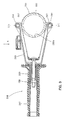
- the dust collecting attachment 350 for hammering operation is configured such that the tip end of the hammer bit (also referred to as a bull point) 219 for hammering operation protrudes a predetermined distance from the front end of the dust collecting cup 351.
- a cup body 353 of the dust collecting cup 351 is conically shaped (trumpet-shaped) such that its inside diameter increases toward the front end. Specifically, the opening area of the cup body 353 is maximized at the front end region.
- the dust collecting cup 351 can be prevented from interfering with the workpiece and thus with the hammering operation, and at the same time, the ability of collecting dust (ease of catching dust) by the dust collecting cup 351 can be increased.
- the dust collecting attachment 350 of this embodiment is suitably constructed for use in hammering operation in which the hammer bit 219 is caused to perform only the striking movement.
- the dust collecting cup 351 includes the cup body 353 and a cup mounting portion 355, and a rear end portion of the cup body 353 is fitted onto a front end portion of the cup mounting portion 355, so that the cup body 353 and the cup mounting portion 355 are connected to each other.
- the dust collecting cup 351 is a feature that corresponds to the "dust collecting member" according to the invention.
- a plurality ofradially inwardly protruding ribs 353a are formed on the inside surface of the cup body 353 and spaced equidistantly in the circumferential direction.
- the ribs 353a are located at a predetermined distance toward the back of the cup body 353 (rearward) from the front end of the cup body 353.
- the ribs 353a serve to define the amount of fit between the cup body 353and the cup mounting portion 355 by contact with the front end surface of the cup mounting portion 355. Moreover, the ribs 353a serve to prevent large concrete pieces in dust from flowing to the cup mounting portion 355 side by filling the clearance between the inner circumferential surface of the cup body 353 and the outer circumferential surface of the hammer bit 219. In this manner, the ribs 353a effectively work to prevent dust clogging on the downstream side.
- the rib 353a is a feature that corresponds to the "region for filling the clearance" according to the invention.
- constructions other than described above relating to the dust collecting attachment 350 for hammering operation are identical to those in the dust collecting attachment 250 for drilling operation as described in the first embodiment. Therefore, all the components of the dust collecting attachment 350 for hammering operation other than the above-described construction are given like numerals as those of the dust collecting attachment 250 for drilling operation and are only briefly described.
- the dust collecting attachment 350 mainly includes the dust collecting cup 351 and the connecting hose 273 which connects the dust collecting cup 351 to a dust collector.
- the connecting hose 273 is bound to the motor housing 205 and a cord guide (not shown) with banding bands 277, and held by the hose holding rib 279 formed on the motor housing 205.
- the cup mounting portion 355 has the dust discharge nozzle 259 to which the connecting hose 273 is connected and the sealing member 263 that fills the clearance between the cup mounting portion 355 and the outer circumferential surface of the hammer bit 219. Further, the cup mounting portion 355 is mounted to the side grip 208 via the two poles 265 which are inserted into the engagement holes 267 of the base 285.
- the engagement protrusion 271a of the engagement member 271 is elastically engaged with the engagement groove 265a of the pole 265, so that the cup mounting portion 355 is retained in the mounting position.
- the two access spaces 269 for bit removal are defined by the two poles 265 in the circumferential direction between the cup mounting portion 355 and the base 285.
- dust generated by hammering operation is collected in the dust collecting cup 351 and then dust collected in the dust collecting cup 351 can be forcibly sucked via the connecting hose 273 by the dust collector. Therefore, a process of disposal of dust accumulated within the dust collecting cup 351, which is required in the construction in which dust is not forcibly collected, can be dispensed with, so that rational dust collection can be realized. Further, it is not necessary to interrupt the operation in order to dispose of the dust collected within the dust collecting cup 351, so that workability can also be improved.
- the ribs 353a formed on the cup body 353 of the dust collecting cup 351 can prevent large concrete pieces from being sucked up to the downstream side and thereby prevent dust clogging.
- the same effects as the first embodiment can be obtained.
- the dust collecting cup 251 or 351 can be attached to the hammer drill 201 by replacing the cup bodies 253, 353 surrounding the hammer bit 219 with each other, according to the operation mode of the hammer bit 219, or according to whether the hammer bit 219 is driven in hammer mode or it is driven in hammer drill mode or drill mode.
- dust can be collected using the dust collecting cup 251 or 351 designed to be suitable for the particular operation.
- the connecting hose 273 can be rationally shared.
- the dust collecting cups 251, 351 are constructed such that the cup bodies 253, 353 are detachably connected to the cup mounting portions 255, 355.
- the hammer mode is a feature that corresponds to the "first operation mode” as described in claim 5 according to the invention.
- the hammer drill mode and the drill mode are features that correspond to the "second operation mode" as defined in claim 5 according to the invention.
- the manner of replacing the dust collecting cups 251, 351 is not limited to the manner of replacing only the cup bodies 253, 353, but it also includes the manner of replacing the dust collecting cups 251, 351 in their entirety including the cup mounting portions 255, 355.
- a dust collecting attachment 350 is used on an electric hammer 301.
- the electric hammer 301 shown in FIG. 10 is of the type in which a driving motor 311 is vertically disposed such that its rotation axis extends in a direction transverse to an axial direction of a hammer bit 319.
- the electric hammer 301 has a generally L-shaped body structure formed by a motor housing 305 and a gear housing 307.
- the electric hammer 301 has the same construction as the hammer drill 201 of the first embodiment except that an internal mechanism for driving the hammer bit 319 does not have a mechanism for transmitting rotation.
- the internal mechanism of the electric hammer 301 includes a motion converting mechanism (crank mechanism) 313 that converts the rotating output of the driving motor 311 into linear motion, and a striking mechanism 315 that linearly moves in the longitudinal direction of the body 303 via components of linear motion of the motion converting mechanism 313 and thereby strikes the hammer bit 319.
- This internal mechanism is known and therefore it is not described in further detail.
- the electric hammer 301 has the tool holding device 204 for holding the hammer bit 319 and a bit angle setting mechanism (variolock mechanism) 330 for setting the angle (positioning in the circumferential direction) of the hammer bit 319 held by the tool holding device 204, in the front end region of the body 303.
- the tool holding device 204 has the same construction as in the above-described first embodiment, and therefore its components are given like numerals and not described.
- the bit angle setting mechanism 330 mainly includes a generally annular lock ring 331 which serves to prevent the tool holding device 204 from rotating around its longitudinal direction and a generally cylindrical lock releasing sleeve 333 for bit angle adjustment which serves to release the tool holding device 204 from rotation prevention by the lock ring 331.
- the lock releasing sleeve 333 is a feature that corresponds to the "operating member for bit angle adjustment" according to the invention.
- the lock ring 331 is disposed on the middle of the tool holder 241 which is a component of the tool holding device 204, in its longitudinal direction, and can slide in the axial direction of the hammer bit 319.
- a lock claw 331a is formed on the inner circumferential surface of the lock ring 331 and engaged with a claw formed on the outside of the tool holder 241. Further, a lock claw 331b is formed on the rear end of the lock ring 331 in the longitudinal direction and engaged with a claw formed on the front end of a fixed sleeve 335 in the longitudinal direction. The fixed sleeve 335 is prevented from moving in the circumferential direction with respect to a barrel 306. With such a construction, the tool holding device 204 is prevented from rotating, so that the hammer bit 319 is prevented from unnecessarily rotating in the circumferential direction during hammering operation.
- the lock releasing sleeve 333 is disposed at the rear of the bit removing tool sleeve 245 of the tool holding device 204 and on the outside of the lock ring 331 such that it can slide in the longitudinal direction together with the lock ring 331.
- the lock claw of the lock ring 331 can be disengaged from the claw ofthe lock sleeve 335, so that rotation of the tool holding device 204 is allowed.
- the front end portion of the lock releasing sleeve 333 in the longitudinal direction extends into the bit removing tool sleeve 245 in the longitudinal direction. Further, an inward flange of an extending end of the lock releasing sleeve 333 is engaged with the front surface of the lock ring 331 and connected thereto via a retaining ring 337, so that the lock releasing sleeve 333 is integrated with the lock ring 331.
- the rear end portion of the lock releasing sleeve 333 is fitted onto the periphery of the front end portion of the barrel 306 and this rear end portion is defined as the knob 333a to be operated by the user's fingers.
- knob 245a of the tool sleeve 245 and the knob 333a of the lock releasing sleeve 333 are adjacent to each other with a predetermined spacing in the axial direction of the hammer bit 319.
- a biasing spring 249 is disposed between the lock releasing sleeve 333 and the bit removing tool sleeve 245 and elastically retains the lock ring 331 in a locked position in which the lock ring 331 is engaged with the claw of the lock sleeve 335 via the lock releasing sleeve 333.
- the dust collecting attachment 350 is now explained.
- the dust collecting attachment 350 according to this embodiment has the same construction as the above-described second embodiment, and therefore its components are given like numerals as in the second embodiment and not described. Further, the connecting hose for connecting the dust collecting cup 351 to a dust collector is not shown.
- the dust collecting cup 351 is mounted to the side grip 208 via the two poles 265 and in this mounted state, the two access spaces 269 for bit removal are defined by the two poles 265 in the circumferential direction between the cup mounting portion 355 and the side grip 208.
- the knob 245a of the tool sleeve 245 for bit removal and the knob 333a of the lock releasing sleeve 333 for bit angle adjustment face the access spaces 269.
- the dust collecting attachment 350 is mounted to the side grip 208 attached to the barrel 306, via the two poles 265. Further, the access spaces 269 are provided in the dust collecting attachment 350 such that the knob 245a of the bit removing tool sleeve 245 in the tool holding device 204 and the knob 333a of the lock releasing sleeve 333 for bit angle adjustment in the bit angle setting mechanism 330 face each other via the access spaces 269. Therefore, according to this embodiment, the user can remove the hammer bit 319 and adjust the angle of the hammer bit 319 with the dust collecting attachment 350 left attached to the side grip 208, so that workability can be improved.
- the dust collecting attachment as defined in claim 1, wherein the dust collecting member includes a cup body which can extend and contract in the longitudinal direction, and a cup mounting portion which can be mounted to the auxiliary handle.”
- the dust collecting attachment as defined in claim 1, wherein the dust collecting member includes a cup body which is conically shaped such that its inside diameter increases toward the front end, and a cup mounting portion which can be mounted to the auxiliary handle.”
Abstract
Description
- The invention relates to a dust collecting attachment for collecting dust generated during operation, which is used on a power tool that performs a predetermined operation on a workpiece by driving a tool bit.
- Japanese patent publication No.
3726437 - According to the above-described known dust collecting cup, dust generated during operation can be collected, but further rationalization of dust collection is desired.
- Accordingly, it is an object of the invention to further rationalize the dust collection of a dust collecting attachment used in a power tool.
- Above described object can be achieved by the claimed invention. According to the invention, a representative dust collecting attachment is provided which is used on a power tool having a tool body, a tool bit which can be coupled to a front end region of the tool body, and an auxiliary handle attached to the tool body. The dust collecting attachment includes a dust collecting member which can be attached to the auxiliary handle in such a manner as to surround the front end region of the tool body around a longitudinal axis of the front end region in order to collect dust generated during operation by the power tool, and a connecting hose for connecting the dust collecting member to a dust collector. The "power tool" in the invention typically represents a hammer in which a tool bit performs a hammering operation on a workpiece by linearly moving in the axial direction, or a hammer drill in which a tool bit performs a hammer drill operation on a workpiece by linearly moving in the axial direction and rotating around its axis.
- The auxiliary handle attached to the tool body is a non-rotational member. The dust collecting attachment according to this invention can be attached to such a non-rotational auxiliary handle. Therefore, the dust collecting attachment can be used on both the power tool in which the tool bit is caused to perform striking movement in the axial direction and the power tool in which the tool bit is caused to perform striking movement in the axial direction and rotation around its axis. Further, the auxiliary handle is a member retrofitted to the tool body. Therefore, with the construction in which the dust collecting attachment is attached to the auxiliary handle, the dust collecting attachment can be applied without making any change or modification to the tool body of the power tool.
- Particularly, according to the invention, the dust collecting attachment has a connecting hose for connecting the dust collecting member to a dust collector. Therefore, dust generated during operation is collected by the dust collecting member and dust within the dust collecting member can be forcibly sucked by the dust collector. With such a construction, an additional process of disposal of dust accumulated in the dust collecting member, which is required in the construction in which dust is not forcibly collected, can be dispensed with, so that rational dust collection can be realized. Further, it is not necessary to interrupt the operation in order to dispose of the dust collected within the dust collecting member, so that workability can also be improved.
- According to a further aspect of the invention, the dust collecting member may preferably have a protrusion on one end of the dust collecting member in the longitudinal direction, and is attached to the auxiliary handle by insertion of the protrusion into a mounting hole formed in the auxiliary handle. With such a construction, the dust collecting member can be easily attached to the auxiliary handle.
- According to a further aspect ofthe invention, the protrusion inserted into the mounting hole may be engaged with a resin spring formed on a wall surface of the mounting hole and thereby retained in an inserted position. The "engagement" is preferably provided by the construction in which the protrusion and the resin spring have a concave and a convex, respectively, which are designed to be engaged with each other when the protrusion is inserted to a predetermined position in the mounting hole. According to the invention, the protrusion inserted into the mounting hole can be retained by the resin spring, so that the dust collecting member can be prevented from unexpectedly becoming detached from the auxiliary handle, for example, due to vibration caused by operation. Further, the resin spring can be integrally formed with a component of the mounting hole, so that manufacturability can be improved.
- According to a further aspect of the invention, two mounting holes and two protrusions may be provided in the circumferential direction of the dust collecting member, and each of the protrusions may preferably be shaped like a cylindrical pin. With such a construction, the protrusions can be easily inserted into the mounting holes and the dust collecting member can be attached to the auxiliary handle with stability.
- According to a further aspect of the invention, a dust collecting attachment may be provided which is used on a power tool that performs a predetermined operation on a workpiece by a tool bit coupled to a front end region of a tool body. The dust collecting attachment may have a dust collecting member for use in a first operation mode in which the tool bit only linearly moves, and this dust collecting member may include a bit surrounding portion that surrounds the tool bit around a longitudinal axis of the front end region of the tool body, and a front end region surrounding portion that surrounds the front end region of the tool body around the longitudinal axis of the front end region. The dust collecting attachment further has a dust collecting member for use in a second operation mode in which the tool bit at least rotates, and this dust collecting member includes a bit surrounding portion that surrounds the tool bit around the longitudinal axis of the front end region of the tool body, and a front end region surrounding portion that surrounds the front end region of the tool body around the longitudinal axis of the front end region. Each of the dust collecting members for use in the first and second operation modes can be disposed in such a manner as to surround the front end region of the power tool around the longitudinal axis in order to collect dust generated by operation of the power tool, and at least the bit surrounding portions of the dust collecting members can be replaced with each other.
- According to the invention, the dust collecting member for use in operation in the first operation mode (hammering operation) in which the tool bit only linearly moves, or the dust collecting member for use in operation in the second operation mode (drilling operation) in which the tool bit at least rotates can be attached to the front end region of the tool body by replacing the bit surrounding portions with each other or by replacing not only the bit surrounding portions but also the dust collecting members in their entirety including the front end region surrounding portions with each other. Therefore, during operation, dust can be collected by using the dust collecting members each designed to efficiently collect dust in assigned operation mode. For example, in hammering operation in the first operation mode, the dust collecting member having the bit surrounding portion which is conically shaped (trumpet-shaped) such that dust (concrete pieces) easily enter the dust collecting member can be used. Further, in drilling operation in the second operation mode, the dust collecting member having the bit surrounding portion which has an extensible structure such that an operation can be performed with the dust collecting member pressed against a workpiece can be used. Thus, according to the invention, rational dust collection can be realized by using the dust collecting members suitable for each operation mode. Particularly, in the construction in which the bit surrounding portions are replaced with each other, the front end region surrounding portions can be rationally shared.
- According to a further aspect of the invention, the dust collecting member for use in the first operation mode may be configured such that an opening area of its front end region in the longitudinal direction is larger than a sectional area of the bit surrounding portion. Further, the first dust collecting member has a region for filling a clearance between an outer circumferential surface of the tool bit and an inner circumferential surface of the dust collecting member in a halfway region in the longitudinal direction. By thus increasing the opening area of the front end region, the dust collecting member can efficiently receive dust. Further, with the construction in which the dust collecting member has the region for filling the clearance between the outer circumferential surface of the tool bit and the inner circumferential surface of the dust collecting member in the halfway region in the longitudinal direction, large concrete pieces can be prevented from being sucked to the downstream side and thereby causing clogging of the hose.
- According to a further aspect of the invention, the dust collecting member may have an opening which is located in a position corresponding to an operating member which is provided for removal of the tool bit and/or for bit angle adjustment in the front end region ofthe power tool, and the operating member can be operated by user's fingers through the opening. With such a construction, the user can operate the operating member through the opening with the dust collecting member left attached to the power tool, so that workability in removal of the tool bit and/or bit angle adjustment can be improved.
- Further, the "operating member" in the invention typically represents a member which is operated to release the tool bit from the tool holding device in order to remove the tool bit held by the tool holding device, and/or, a member for adjusting the angle of the tool bit held by the tool holding device to a predetermined angle when the power tool performs in hammer mode in which the tool bit is caused to linearly move in its axial direction.
- According to a further aspect of the invention, the dust collecting member may have a fastener for fastening the connecting hose to the tool body of the power tool. Thus, the connecting hose can be fastened to the tool body along its outer surface. As a result, the connecting hose is prevented from hanging down and swinging during operation and thus prevented from interfering with the operation.
- According to a further aspect of the invention, the fastener may comprise a band-like member for binding the connecting hose to the tool body. With such a construction, the connecting hose can be easily fastened to the tool body. Further, the manner of "binding" typically represents tying or strapping, but widely includes other manners such as fastening by a hook-and-loop fastener.
- According to a further aspect of the invention, the connecting hose may be held by a supplementary fixing rib which is formed on the tool body and conforms to an outer circumferential surface of the connecting hose. With such a construction, the connecting hose can be held fastened to the tool body with higher stability.
- According to a further aspect of the invention, a power tool may be provided which has the dust collecting attachment as defined in any one of claims 1 to 10. Thus, the power tool can be provided with the dust collecting attachment having an improved dust collecting effect.
- Other objects, features and advantages of the present invention will be readily understood after reading the following detailed description together with the accompanying drawings and the claims.
-
-
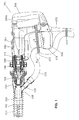
FIG. 1 is a partially sectional view showing an entire structure of a hammer drill with a dust collecting attachment for use in hammer drill operation according to a first embodiment of the invention. -
FIG. 2 is an enlarged view showing part (the dust collecting attachment side) ofFIG. 1 . -
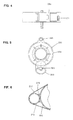
FIG. 3 is a sectional view showing a side grip to which the dust collecting attachment is attached. -
FIG. 4 is a view as viewed from the direction shown by the arrow A inFIG. 3 . -
FIG. 5 is a view showing the dust collecting attachment as viewed from the rear of the hammer drill (from the right side as viewed inFIG. 1 ). -
FIG. 6 is a sectional view taken along line B-B inFIG. 1 . -
FIG. 7 is a view showing a dust collecting attachment for use in hammering operation according to a second embodiment of the invention. -
FIG. 8 is an enlarged view showing the dust collecting attachment for use in hammering operation. -
FIG. 9 is a view showing a cup body of a dust collecting cup of the dust collecting attachment for use in hammering operation as viewed from the front of the hammer drill (from the left side as viewed inFIG. 7 ). -
FIG. 10 is a sectional view showing an entire structure of a hammer with a dust collecting attachment attached thereto according to a third embodiment of the invention. -
FIG. 11 is an enlarged view showing part (the dust collecting attachment side) ofFIG. 10 . - Each of the additional features and method steps disclosed above and below may be utilized separately or in conjunction with other features and method steps to provide and manufacture improved dust collecting attachments and method for using such dust collecting attachments and devices utilized therein. Representative examples ofthe present invention, which examples utilized many of these additional features and method steps in conjunction, will now be described in detail with reference to the drawings. This detailed description is merely intended to teach a person skilled in the art further details for practicing preferred aspects of the present teachings and is not intended to limit the scope of the invention. Only the claims define the scope of the claimed invention. Therefore, combinations of features and steps disclosed within the following detailed description may not be necessary to practice the invention in the broadest sense, and are instead taught merely to particularly describe some representative examples of the invention, which detailed description will now be given with reference to the accompanying drawings.
- A first embodiment of the invention is now described with reference to
FIGS. 1 to 6 . In this embodiment, a dust collecting attachment is used on an electric hammer drill which is a representative example of a power tool. Firstly, a hammer drill on which the dust collecting attachment is used is explained. As shown inFIGS. 1 and2 , ahammer drill 201 mainly includes abody 203 that forms an outer shell of thehammer drill 201, ahammer bit 219 detachably coupled to a tip end region (front end portion) of thebody 203 via atool holding device 204 and ahandgrip 209 that is designed as a main handle and disposed on a side (rear end portion) of thebody 203 opposite from thehammer bit 219. Thehammer bit 219 is held by thetool holding device 204 such that it is allowed to move with respect to thetool holding device 204 in its axial direction and prevented from rotating with respect to the tool holding device in its circumferential direction. Thebody 203 and thehammer bit 219 are features that correspond to the "tool body" and the "tool bit", respectively, according to the invention. For the sake of convenience of explanation, the side of thehammer bit 219 is taken as the front and the side of thehandgrip 209 as the rear. - The
body 203 mainly includes amotor housing 205 that houses a driving motor (not shown), and agear housing 207 that houses an internal mechanism related to striking movement and rotation of thehammer bit 219. In this embodiment, the driving motor is disposed such that its rotation axis extends in a direction transverse to the axial direction of thehammer bit 219. Therefore, as shown inFIG. 1 , thebody 203 has a generally L-shaped body structure formed by themotor housing 205 and thegear housing 207. Further, thehandgrip 209 disposed on the rear end of thebody 203 is configured as a generally D-shaped handle extending in the vertical direction transverse to the axial direction of thehammer bit 219 and having upper and lower ends connected to thebody 203. Acylindrical barrel 206 is provided on the front of thegear housing 207 and theside grip 208 is detachably attached to thebarrel 206. Theside grip 208 is a feature that corresponds to the "auxiliary handle" according to the invention. Attachment of theside grip 208 is described below. - Further, the internal mechanism mainly includes a crank mechanism (not shown) as a motion converting mechanism, a
striking mechanism 215 and a power transmitting mechanism (not shown). The crank mechanism converts the rotating output of the driving motor into linear motion. Thestriking mechanism 215 linearly moves in the longitudinal direction of thebody 203 via components of linear motion of the crank mechanism and thereby strikes thehammer bit 219. The power transmitting mechanism appropriately reduces the speed of the rotating output of the driving motor and transmits it to thehammer bit 219 and thereby causes thehammer bit 219 to rotate in the circumferential direction. Thestriking mechanism 215 mainly includes a striking element in the form of astriker 235 that linearly moves, and an intermediate element in the form of animpact bolt 237 that transmits the striking force of thestriker 235 to the hammer bit 219 (seeFIG. 2 ). Further, a specific structure of causing thehammer bit 219 to perform the striking movement and rotation via the internal mechanism is known and therefore it is not described in further detail. - As shown in
FIG. 2 , thetool holding device 204 mainly includes acylindrical tool holder 241 with abit insert hole 241a having a circular section into which the stem of thehammer bit 219 is removably inserted, a removal preventing member in the form of a plurality ofengagement claws 243 which prevent removal of thehammer bit 219 inserted into thebit insert hole 241a, and a generallycylindrical tool sleeve 245 that can be operated to release thehammer bit 219 from removal prevention by theengagement claws 243. Thetool sleeve 245 is disposed in front of thebarrel 206 of thegear housing 207 such that it can be moved by the user in the axial direction of thehammer bit 219. Thetool sleeve 245 is normally biased forward by a biasingspring 249 and retains theengagement claws 243 in the removal preventing position (as shown in the drawing) via a retainingring 247. When thetool sleeve 245 is slid rearward (toward the handgrip), the bit removal prevention by theengagement claws 243 is released. Thetool sleeve 245 is a feature that corresponds to the "operation member for removal of the tool bit" according to the invention. - In the
hammer drill 201 constructed as described above, when the driving motor is driven by depressing a trigger 209a, the rotating output of the driving motor is converted into linear motion via the motion converting mechanism and then transmitted as linear motion in the axial direction to thehammer bit 219 via the striking mechanism. As a result, thehammer bit 219 perform linear movement (hereinafter also referred to as striking movement). Further, rotation is transmitted to thetool holding device 204 via the power transmitting mechanism driven by the rotating output of the driving motor, so that thehammer bit 219 held by thetool holding device 204 is caused to rotate in the circumferential direction. Specifically, thehammer bit 219 performs a hammer drill (drilling) operation on a workpiece (concrete) by striking movement in the axial direction and rotation in the circumferential direction. - The
hammer drill 201 can be switched not only to the hammer drill mode in which the hammer bit 119 is caused to perform striking movement in the axial direction and rotation in the circumferential direction as described above, but to the drill mode in which the hammer bit 119 is caused to perform only rotation, or the hammer mode in which the hammer bit 119 is caused to perform only striking movement. This mode switching is a known technique and not directly related to the invention, and therefore its description is omitted. - The
hammer drill 201 constructed as described above generates dust during operation on a workpiece (such as concrete). In order to collect the dust, thedust collecting attachment 250 according to this embodiment is mounted to theside grip 208. Therefore, theside grip 208 is described before explanation of thedust collecting attachment 250. Theside grip 208 is mounted to thebarrel 206 of thegear housing 207. To this end, agrip mounting portion 281 is formed on the outer surface of thebarrel 206 by a circumferential surface having a predetermined width and extending parallel to the longitudinal direction of thebody 203. As shown inFIG. 3 , theside grip 208 is configured as a rod-like member extending in a direction transverse to the axial direction of thehammer bit 219 as a whole. - As shown in
FIG. 3 , theside grip 208 mainly includes aband 283 wrapped around the outer surface of thegrip mounting portion 281 of thebarrel 206, abase 285 having a generallyU-shaped engagement surface 285a which is disposed on the end of theband 283 and engaged with the outer surface of thegrip mounting portion 281, agrip 287 which is connected to thebase 285 and can rotate around its longitudinal axis, and a threadedoperation rod 289 for tightening theband 283. Theoperation rod 289 is loosely inserted through the central portions of thegrip 287 and thebase 285 and extends in the longitudinal direction ofthe grip. One end of theoperation rod 289 is connected to the end of theband 283 and the other end is threadably engaged with anut 286 disposed within thegrip 287. Thenut 286 is prevented from rotating with respect to thegrip 287. Therefore, by rotating thegrip 287 clockwise or counterclockwise around its longitudinal axis, the threadedoperation rod 289 threadably engaged with thenut 286 is moved forward or rearward in the longitudinal direction, so that theband 283 can be tightened or loosened. Theside grip 208 is fixed to thegrip mounting portion 281 by tightening theband 283. In this embodiment, theside grip 208 is mounted to thebody 203 and protrudes substantially horizontally in a lateral direction of thebody 203. - The
dust collecting attachment 250 is now explained. Thedust collecting attachment 250 according to this embodiment is designed for drilling operation in which thehammer bit 219 is driven in hammer drill mode or drill mode. As shown inFIG. 2 , thedust collecting attachment 250 mainly includes adust collecting cup 251 which has a cylindrical shape having both ends open and covers the front end region of thebody 203 including thehammer bit 219, and a connectinghose 273 which connects thedust collecting cup 251 to a dust collector. Thedust collecting cup 251 is a feature that corresponds to the "dust collecting member" according to the invention. Thedust collecting cup 251 includes an extensiblebellows cup body 253, and a cylindricalcup mounting portion 255 which is connected to one end (rear end) of thecup body 253 in the longitudinal direction (in the direction of expansion and contraction). When thedust collecting cup 251 is attached to theside grip 208, thecup body 253 surrounds and covers thehammer bit 219, and thecup mounting portion 255 surrounds and covers the front end portion of thebody 203 or thetool holding device 204 which holds thehammer bit 219. Thecup body 253 and thecup mounting portion 255 are features that correspond to the "bit surrounding portion" and the "front end region surrounding portion", respectively, according to the invention. Further, adust discharge nozzle 259 and a sealingmember 263 are provided on thecup mounting portion 255 in its region of connection with thecup body 253. Thedust discharge nozzle 259 is open to the internal space of thecup mounting portion 255, and the sealingmember 263 serves to fill a clearance between thecup mounting portion 255 and the stem of thehammer bit 219. Thedust discharge nozzle 259 is a feature that corresponds to the "hose connecting port" according to the invention. Further, as shown inFIG. 1 , thedust collecting cup 251 of thedust collecting attachment 250 for use in drilling operation has such a longitudinal length that it almost entirely covers the hammer bit (which is also referred to as drill) 219 for drilling operation. - As shown in
FIG. 5 , twopoles 265 having a circular section are provided on the rear end of the cup mounting portion 255 (on thebody 203 side) in order to mount thecup mounting portion 255 to theside grip 208. Thepoles 265 extend rearward in parallel to each other and are spaced 180 degrees apart from each other in the circumferential direction. Correspondingly, as shown inFIG. 3 , twoengagement holes 267 which face thecup mounting portion 255 are formed in thebase 285 of theside grip 208. As shown inFIG. 2 , an end (rear end) of each of thepoles 265 is inserted into the associatedengagement hole 267, so that thecup mounting portion 255 is mounted to thebase 285 of theside grip 208 in such a manner as to face the base 285 with a predetermined spacing in the axial direction of thehammer bit 219. Thepole 265 and theengagement hole 267 are features that correspond to the "protrusion" and the "mounting hole", respectively, according to the invention. - In this embodiment, by provision of the two
poles 265 protruding rearward from thecup mounting portion 255, two generally U-shaped spaces surrounded by the rear surface of thecup mounting portion 255 and the twopoles 265 and having an open rear end are defined at the rear of thecup mounting portion 255. As shown inFIG. 2 , when thecup mounting portion 255 is mounted to theside grip 208 with a predetermined spacing in the axial direction of thehammer bit 219 via thepoles 265, twoaccess spaces 269 are defined by the rear surface of thecup mounting portion 255, the front surface of thebase 285 and the twopoles 265 between the base 285 of theside grip 208 and thecup mounting portion 255. Thus, the user can operate the rear end of thetool sleeve 245 of thetool holding device 204, or aknob 245a, by the fingers through theaccess spaces 269. Theaccess space 269 is a feature that corresponds to the "opening" according to the invention. Further, the length of theaccess space 269 in the longitudinal direction can be appropriately set by changing the length of thepoles 265. - As shown in
FIGS. 2 to 4 , anengagement member 271 is provided on thebase 285 of theside grip 208 and has a generallysemicircular engagement protrusion 271a which protrudes radially inward into theengagement hole 267. When thepole 265 of thedust collecting cup 251 is inserted into the associatedengagement hole 267, theengagement member 271 is elastically engaged with anannular engagement groove 265a formed in the outer circumferential surface of thepole 265 and thereby retains thepole 265 in the inserted position. Thus, theengagement member 271 is provided as a pole retaining member. When thepole 265 is pulled forward, theengagement member 271 is elastically deformed radially outward, so that theengagement protrusion 271a is disengaged from theengagement groove 265a. Thus, thepole 265 can be removed from theengagement hole 267. Theengagement member 271 is a feature that corresponds to the "resin spring" according to the invention. - A connecting
hose 273 for connecting thedust discharge nozzle 259 to a dust collector can be connected to thedust discharge nozzle 259. As shown inFIG. 1 , the connectinghose 273 connected to thedust discharge nozzle 259 extends from thedust discharge nozzle 259 to thebody 203 or to the front of themotor housing 205 and extends downward along the front surface of themotor housing 205. The connectinghose 273 is bound to themotor housing 205 and to acord guard 275 which extends downward from themotor housing 205 and serves to protect a power cord, with bandingbands 277, such that the connectinghose 273 is prevented from hanging down and swinging during operation. The banding band is a feature that corresponds to the "fastener" and "band-like member" according to the invention. - Further, a
hose holding rib 279 is formed on the front surface of themotor housing 205 and has a concave portion which conforms to an outer circumferential surface of the connectinghose 273. As shown inFIG. 6 , the outer surface of the connectinghose 273 is engaged with the concave portion of thehose holding rib 279, so that the movement of the connectinghose 273 bound with the bandingbands 277 is further prevented. Thus, the stability of the connectinghose 273 is further improved. Thehose holding rib 279 is a feature that corresponds to the "hose holding portion" according to the invention. - The
dust collecting attachment 250 according to this embodiment is constructed as described above. Drilling operation on a workpiece (concrete) by thehammer drill 201 is performed with the front end of thedust collecting cup 251 pressed against the workpiece. Thedust collecting cup 251 according to this embodiment has an extensiblebellows cup body 253 on its front end, so that thecup body 253 contracts as thebody 203 moves toward the workpiece by drilling movement of thehammer bit 219. As a result, dust collection suitable for drilling operation can be realized. Then dust generated by drilling operation is collected by thedust collecting cup 251 and forcibly sucked from thedust discharge nozzle 259 via the connectinghose 273 by a dust collector. - As described above, according to this embodiment, dust generated during drilling operation can be collected in the
dust collecting cup 251, and at the same time, the dust collected in thedust collecting cup 251 can be forcibly sucked by the dust collector. Therefore, an additional process of disposal of dust accumulated within thedust collecting cup 251, which is required in the construction in which dust is simply collected in the dust collecting cup, can be dispensed with, so that rational dust collection can be realized. Further, it is not necessary to interrupt the operation in order to dispose of the dust collected within thedust collecting cup 251, so that workability can also be improved. - Further, in this embodiment, the
dust collecting attachment 250 is attached to theside grip 208 of the type which is retrofitted to thebody 203 of thehammer drill 201. Therefore, thedust collecting attachment 250 can be applied without making any change or modification to thebody 203 of thehammer drill 201. Further, theside grip 208 is configured as a non-rotational member, so that theside grip 208 can be suitably used for drilling operation in which thehammer drill 201 is driven in hammer drill mode or in drill mode. - Further, the
dust collecting attachment 250 is attached to theside grip 208 via the twopoles 265. At this time, in this embodiment, the protruding direction of thedust discharge nozzle 259 of thedust collecting cup 251 has a phase difference of about 90 degrees in the circumferential direction with respect to the protruding direction of theside grip 208 attached to thebody 203. With this construction, even though thedust collecting cup 251 is attached to theside grip 208, the connectinghose 273 connected to thedust discharge nozzle 259 can be prevented from interfering with the user's hand holding theside grip 208. Further, the connectinghose 273 is fixed by thebanding band 277 so as to extend along thebody 203, so that the connectinghose 273 can be prevented from hanging down and swinging. Therefore, when the user holds theside grip 208 and performs an operation, the connectinghose 273 is prevented from interfering with the operation, so that workability can be improved. - Further, in this embodiment, the two
access spaces 269 for bit removal are defined by the twopoles 265 in the circumferential direction, so that the user can operate aknob 245a of thetool sleeve 245 of thetool holding device 204 by the fingers through theaccess spaces 269. Therefore, in the state in which thedust collecting attachment 250 is left attached to thebody 203, the user can move thetool sleeve 245 of thetool holding device 204 rearward by the fingers through the twoaccess spaces 269. As a result, thehammer bit 219 can be released from removal prevention of theengagement claw 243, so that thehammer bit 219 can be removed from thebit insert hole 241a of thetool holder 241 of thetool holding device 204. Specifically, thehammer bit 219 can be removed with thedust collecting attachment 250 left attached to thebody 203. - In the
hammer drill 201 which can be switched to the hammer mode in which thehammer bit 219 is caused to perform only a striking movement, a bit angle setting mechanism (a variolock mechanism) is provided which serves to prevent rotation of the hammer bit 219 (to forcibly lock thetool holder 241 of thetool holding device 204 to the gear housing 207) in order to keep the angle of thehammer bit 219 constant (to prevent thehammer bit 219 from moving in the circumferential direction) during operation in hammer mode. The angle setting mechanism of thehammer bit 219 is configured such that thehammer bit 219 is released from the rotation prevention halfway through the operation of switching the operation mode of thehammer bit 219, for example, from hammer drill mode to hammer mode, by an operation mode switching lever, and when the switching operation to hammer mode is completed, thehammer bit 219 is again prevented from rotating. Therefore, the angle setting of thehammer bit 219 can be made by turning thetool sleeve 245 of thetool holding device 204 in the circumferential direction by the user's fingers in the halfway region of the switching movement in which thehammer bit 219 is not prevented from rotating by the bit angle setting mechanism. Specifically, with thedust collecting attachment 250 according to this embodiment, the angle setting of thehammer bit 219 can be made through the bitremoval access spaces 269 with thedust collecting attachment 250 left attached to thebody 203. - A
dust collecting attachment 350 according to a second embodiment of the invention is now explained with reference toFIGS. 7 to 9 . Thedust collecting attachment 350 according to the second embodiment is changed from the construction designed for drilling operation to the construction designed for hammering operation. Therefore, thedust collecting attachment 350 can be applied not only to a hammer in which the hammer bit only linearly moves, but also to a hammer drill that can be switched between hammer mode in which the hammer bit only linearly moves and hammer drill mode in which the hammer bit linearly moves and rotates. Further, as well known, the hammer has the same structure as the hammer drill, except that the hammer does not have the power transmitting mechanism for rotating the hammer bit. - This embodiment is applied to the
hammer drill 201 described in the first embodiment for the sake of convenience. Therefore, components of thehammer drill 201 including thetool holding device 204 and components of theside grip 208 attached to thehammer drill 201 are given like numerals as in the first embodiment and not described. - In this embodiment, as shown in
FIGS. 7 and8 , thedust collecting attachment 350 for hammering operation is configured such that the tip end of the hammer bit (also referred to as a bull point) 219 for hammering operation protrudes a predetermined distance from the front end of thedust collecting cup 351. Further, acup body 353 of thedust collecting cup 351 is conically shaped (trumpet-shaped) such that its inside diameter increases toward the front end. Specifically, the opening area of thecup body 353 is maximized at the front end region. With such a configuration, thedust collecting cup 351 can be prevented from interfering with the workpiece and thus with the hammering operation, and at the same time, the ability of collecting dust (ease of catching dust) by thedust collecting cup 351 can be increased. Specifically, thedust collecting attachment 350 of this embodiment is suitably constructed for use in hammering operation in which thehammer bit 219 is caused to perform only the striking movement. - The
dust collecting cup 351 includes thecup body 353 and acup mounting portion 355, and a rear end portion of thecup body 353 is fitted onto a front end portion of thecup mounting portion 355, so that thecup body 353 and thecup mounting portion 355 are connected to each other. Thedust collecting cup 351 is a feature that corresponds to the "dust collecting member" according to the invention. A plurality ofradially inwardly protruding ribs 353a are formed on the inside surface of thecup body 353 and spaced equidistantly in the circumferential direction. The ribs 353a are located at a predetermined distance toward the back of the cup body 353 (rearward) from the front end of thecup body 353. The ribs 353a serve to define the amount of fit between the cup body 353and thecup mounting portion 355 by contact with the front end surface of thecup mounting portion 355. Moreover, the ribs 353a serve to prevent large concrete pieces in dust from flowing to thecup mounting portion 355 side by filling the clearance between the inner circumferential surface of thecup body 353 and the outer circumferential surface of thehammer bit 219. In this manner, the ribs 353a effectively work to prevent dust clogging on the downstream side. The rib 353a is a feature that corresponds to the "region for filling the clearance" according to the invention. - Further, constructions other than described above relating to the
dust collecting attachment 350 for hammering operation are identical to those in thedust collecting attachment 250 for drilling operation as described in the first embodiment. Therefore, all the components of thedust collecting attachment 350 for hammering operation other than the above-described construction are given like numerals as those of thedust collecting attachment 250 for drilling operation and are only briefly described. - The
dust collecting attachment 350 mainly includes thedust collecting cup 351 and the connectinghose 273 which connects thedust collecting cup 351 to a dust collector. The connectinghose 273 is bound to themotor housing 205 and a cord guide (not shown) with bandingbands 277, and held by thehose holding rib 279 formed on themotor housing 205. Thecup mounting portion 355 has thedust discharge nozzle 259 to which the connectinghose 273 is connected and the sealingmember 263 that fills the clearance between thecup mounting portion 355 and the outer circumferential surface of thehammer bit 219. Further, thecup mounting portion 355 is mounted to theside grip 208 via the twopoles 265 which are inserted into the engagement holes 267 of thebase 285. Further, theengagement protrusion 271a of theengagement member 271 is elastically engaged with theengagement groove 265a of thepole 265, so that thecup mounting portion 355 is retained in the mounting position. In the mounted state of thecup mounting portion 355, the twoaccess spaces 269 for bit removal are defined by the twopoles 265 in the circumferential direction between thecup mounting portion 355 and thebase 285. - In the
dust collecting attachment 350 which is constructed as described above and used in hammering operation, dust generated by hammering operation is collected in thedust collecting cup 351 and then dust collected in thedust collecting cup 351 can be forcibly sucked via the connectinghose 273 by the dust collector. Therefore, a process of disposal of dust accumulated within thedust collecting cup 351, which is required in the construction in which dust is not forcibly collected, can be dispensed with, so that rational dust collection can be realized. Further, it is not necessary to interrupt the operation in order to dispose of the dust collected within thedust collecting cup 351, so that workability can also be improved. - Further, in this embodiment, the ribs 353a formed on the
cup body 353 of thedust collecting cup 351 can prevent large concrete pieces from being sucked up to the downstream side and thereby prevent dust clogging. - According to the
dust collecting attachment 350 of this embodiment, as for attachment of thedust collecting attachment 350 to theside grip 208 and attachment of the connectinghose 273 to thedust collecting attachment 350, the same effects as the first embodiment can be obtained. - Further, when the
dust collecting attachment 250 for use in drilling operation and thedust collecting attachment 350 for use in hammering operation are used on thehammer drill 201, thedust collecting cup hammer drill 201 by replacing thecup bodies hammer bit 219 with each other, according to the operation mode of thehammer bit 219, or according to whether thehammer bit 219 is driven in hammer mode or it is driven in hammer drill mode or drill mode. With such a construction, dust can be collected using thedust collecting cup hose 273 can be rationally shared. In this case, thedust collecting cups cup bodies cup mounting portions - Further, the manner of replacing the
dust collecting cups cup bodies dust collecting cups cup mounting portions - A third embodiment of the invention is now explained with reference to
FIGS. 10 and11 . In this embodiment, adust collecting attachment 350 is used on anelectric hammer 301. Like thehammer drill 201 according to the first embodiment, theelectric hammer 301 shown inFIG. 10 is of the type in which a drivingmotor 311 is vertically disposed such that its rotation axis extends in a direction transverse to an axial direction of ahammer bit 319. Further, theelectric hammer 301 has a generally L-shaped body structure formed by amotor housing 305 and agear housing 307. Theelectric hammer 301 has the same construction as thehammer drill 201 of the first embodiment except that an internal mechanism for driving thehammer bit 319 does not have a mechanism for transmitting rotation. Specifically, the internal mechanism of theelectric hammer 301 includes a motion converting mechanism (crank mechanism) 313 that converts the rotating output of the drivingmotor 311 into linear motion, and astriking mechanism 315 that linearly moves in the longitudinal direction of thebody 303 via components of linear motion of themotion converting mechanism 313 and thereby strikes thehammer bit 319. This internal mechanism is known and therefore it is not described in further detail. - As shown in
FIG. 11 , theelectric hammer 301 according to this embodiment has thetool holding device 204 for holding thehammer bit 319 and a bit angle setting mechanism (variolock mechanism) 330 for setting the angle (positioning in the circumferential direction) of thehammer bit 319 held by thetool holding device 204, in the front end region of thebody 303. Further, thetool holding device 204 has the same construction as in the above-described first embodiment, and therefore its components are given like numerals and not described. - The bit
angle setting mechanism 330 mainly includes a generallyannular lock ring 331 which serves to prevent thetool holding device 204 from rotating around its longitudinal direction and a generally cylindricallock releasing sleeve 333 for bit angle adjustment which serves to release thetool holding device 204 from rotation prevention by thelock ring 331. Thelock releasing sleeve 333 is a feature that corresponds to the "operating member for bit angle adjustment" according to the invention. Thelock ring 331 is disposed on the middle of thetool holder 241 which is a component of thetool holding device 204, in its longitudinal direction, and can slide in the axial direction of thehammer bit 319. A lock claw 331a is formed on the inner circumferential surface of thelock ring 331 and engaged with a claw formed on the outside of thetool holder 241. Further, alock claw 331b is formed on the rear end of thelock ring 331 in the longitudinal direction and engaged with a claw formed on the front end of a fixedsleeve 335 in the longitudinal direction. The fixedsleeve 335 is prevented from moving in the circumferential direction with respect to abarrel 306. With such a construction, thetool holding device 204 is prevented from rotating, so that thehammer bit 319 is prevented from unnecessarily rotating in the circumferential direction during hammering operation. - The
lock releasing sleeve 333 is disposed at the rear of the bit removingtool sleeve 245 of thetool holding device 204 and on the outside of thelock ring 331 such that it can slide in the longitudinal direction together with thelock ring 331. When the user holds a knob 333a of thelock releasing sleeve 333 and slides it forward, the lock claw of thelock ring 331 can be disengaged from the claw ofthe locksleeve 335, so that rotation of thetool holding device 204 is allowed. - The front end portion of the
lock releasing sleeve 333 in the longitudinal direction extends into the bit removingtool sleeve 245 in the longitudinal direction. Further, an inward flange of an extending end of thelock releasing sleeve 333 is engaged with the front surface of thelock ring 331 and connected thereto via a retainingring 337, so that thelock releasing sleeve 333 is integrated with thelock ring 331. The rear end portion of thelock releasing sleeve 333 is fitted onto the periphery of the front end portion of thebarrel 306 and this rear end portion is defined as the knob 333a to be operated by the user's fingers. Thus, theknob 245a of thetool sleeve 245 and the knob 333a of thelock releasing sleeve 333 are adjacent to each other with a predetermined spacing in the axial direction of thehammer bit 319. Further, a biasingspring 249 is disposed between thelock releasing sleeve 333 and the bit removingtool sleeve 245 and elastically retains thelock ring 331 in a locked position in which thelock ring 331 is engaged with the claw of thelock sleeve 335 via thelock releasing sleeve 333. - The
dust collecting attachment 350 is now explained. Thedust collecting attachment 350 according to this embodiment has the same construction as the above-described second embodiment, and therefore its components are given like numerals as in the second embodiment and not described. Further, the connecting hose for connecting thedust collecting cup 351 to a dust collector is not shown. Thedust collecting cup 351 is mounted to theside grip 208 via the twopoles 265 and in this mounted state, the twoaccess spaces 269 for bit removal are defined by the twopoles 265 in the circumferential direction between thecup mounting portion 355 and theside grip 208. Theknob 245a of thetool sleeve 245 for bit removal and the knob 333a of thelock releasing sleeve 333 for bit angle adjustment which are described above face theaccess spaces 269. - Specifically, in this embodiment, in the
electric hammer 301 having thetool holding device 204 for holding thehammer bit 319 in the front end region of thebody 303 and a bitangle locking mechanism 330 for locking the angle of thehammer bit 319 held by thetool holding device 204, thedust collecting attachment 350 is mounted to theside grip 208 attached to thebarrel 306, via the twopoles 265. Further, theaccess spaces 269 are provided in thedust collecting attachment 350 such that theknob 245a of the bit removingtool sleeve 245 in thetool holding device 204 and the knob 333a of thelock releasing sleeve 333 for bit angle adjustment in the bitangle setting mechanism 330 face each other via theaccess spaces 269. Therefore, according to this embodiment, the user can remove thehammer bit 319 and adjust the angle of thehammer bit 319 with thedust collecting attachment 350 left attached to theside grip 208, so that workability can be improved. - In view of the scope and spirit of the above-described invention, the following aspects can be provided.
- "The dust collecting attachment as defined in claim 1, wherein the dust collecting member includes a cup body which can extend and contract in the longitudinal direction, and a cup mounting portion which can be mounted to the auxiliary handle."
- "The dust collecting attachment as defined in claim 1, wherein the dust collecting member includes a cup body which is conically shaped such that its inside diameter increases toward the front end, and a cup mounting portion which can be mounted to the auxiliary handle."
- A dust collecting attachment used on a power tool that performs a predetermined operation on a workpiece by a tool bit coupled to a front end region of a tool body characterized by:
- a dust collecting member for use in a first operation mode in which the tool bit only linearly moves, the dust collecting member including a bit surrounding portion that surrounds the tool bit around a longitudinal axis of the front end region of the tool body, and a front end region surrounding portion that surrounds the front end region of the tool body around the longitudinal axis of the front end region, and
- a dust collecting member for use in a second operation mode in which the tool bit at least rotates, the dust collecting member including a bit surrounding portion that surrounds the tool bit around the longitudinal axis of the front end region of the tool body, and a front end region surrounding portion that surrounds the front end region of the tool body around the longitudinal axis of the front end region,
- wherein each of the dust collecting members for use in the first and second operation modes can be disposed in such a manner as to surround the front end region of the power tool around the longitudinal axis in order to collect dust generated by operation of the power tool, and at least the bit surrounding portions of the dust collecting members can be replaced with each other.
- The dust collecting attachment as defined in
Aspect 3, wherein the dust collecting member for use in the first operation mode is configured such that an opening area of the front end region in the longitudinal direction is larger than a sectional area of the bit surrounding portion, and the first dust collecting member has a region for filling a clearance between an outer circumferential surface of the tool bit and an inner circumferential surface of the dust collecting member in a halfway region in the longitudinal direction. - A power tool having the dust collecting attachment as defined in
Aspect 3 or 4. It is explicitly stated that all features disclosed in the description and/or the claims are intended to be disclosed separately and independently from each other for the purpose of original disclosure as well as for the purpose of restricting the claimed invention independent of the composition of the features in the embodiments and/or the claims. It is explicitly stated that all value ranges or indications of groups of entities disclose every possible intermediate value or intermediate entity for the purpose of original disclosure as well as for the purpose of restricting the claimed invention, in particular as limits of value ranges. -
- 201 hammer drill (power tool)
- 203 body
- 204 tool holding device
- 205 motor housing
- 206 barrel
- 207 gear housing
- 208 side grip (auxiliary handle)
- 209 handgrip
- 209a trigger
- 215 striking mechanism
- 219 hammer bit (tool bit)
- 235 striker
- 237 impact bolt
- 241 tool holder
- 241a bit insert hole
- 243 engagement claw
- 245 tool sleeve (operating member)
- 245a knob
- 247 retaining ring
- 249 biasing spring
- 250 dust collecting attachment
- 251 dust collecting cup (dust collecting member)
- 253 cup body
- 255 cup mounting portion
- 259 dust discharge nozzle
- 263 sealing member
- 265 pole
- 265a engagement groove
- 267 engagement hole
- 269 access hole (opening)
- 271 engagement member
- 271a engagement protrusion
- 273 connecting hose
- 275 cord guard
- 277 banding band
- 279 hose holding rib
- 281 grip mounting portion
- 283 band
- 285 base
- 285a engagement surface
- 286 nut
- 287 grip
- 289 threaded operation rod
- 301 electric hammer (power tool)
- 303 body
- 305 motor housing
- 306 barrel
- 307 gear housing
- 311 driving motor
- 313 motion converting mechanism
- 315 striking mechanism
- 319 hammer bit
- 330 bit angle setting mechanism
- 331 lock ring
- 331a lock claw
- 331b lock claw
- 333 lock releasing sleeve (operating member)
- 333a knob
- 335 fixed sleeve
- 337 retaining ring
- 350 dust collecting attachment
- 351 dust collecting cup (dust collecting member)
- 353 cup body
- 355 cup mounting portion
-
- 1. A dust collecting attachment (250; 350) used on a power tool (201; 301) having a tool body (203; 303) and an auxiliary handle (208) attached to the tool body (203; 303), wherein a tool bit (219; 319) can be coupled to a front end region of the tool body (203; 303) characterized by:
- a dust collecting member (251; 351) which can be attached to the auxiliary handle (208) in such a manner as to surround the front end region of the tool body (203; 303) around a longitudinal axis of the front end region in order to collect dust generated during operation by the power tool (201; 301) and
- a connecting hose (273) for connecting the dust collecting member (251; 351) to a dust collector.
- 2. The dust collecting attachment (250; 350) as defined in aspect 1, wherein the dust collecting member (251; 351) has a protrusion (265) on one end of the dust collecting member (251; 351) in the longitudinal direction, and is attached to the auxiliary handle (208) by insertion of the protrusion (265) into a mounting hole (267) formed in the auxiliary handle (208).
- 3. The dust collecting attachment (250; 350) as defined in aspect 2, wherein the protrusion (265) inserted into the mounting hole (267) is engaged with a resin spring (271) formed on a wall surface of the mounting hole (267) and thereby retained in an inserted position.
- 4. The dust collecting attachment (250; 350) as defined in
aspect 2 or 3, wherein two mounting holes (267) and two protrusions (265) are provided in the circumferential direction of the dust collecting member (251; 351), and each of the protrusions (265) is shaped like a cylindrical pin. - 5. The dust collecting attachment (250; 350) as defined in any one of aspects 1 to 4, wherein the dust collecting member (251; 351) has an opening (269) which is located in a position corresponding to an operating member (245; 333) which is provided for removal of the tool bit (219; 319) and/or for bit angle adjustment in the front end region of the power tool (201; 301), and the operating member can be operated by user's fingers through the opening (269).
- 6. The dust collecting attachment (250; 350) as defined in any one of aspects 1 to 5, further comprising a fastener (277) that fastens the connecting hose (273) to the tool body (203; 303).
- 7. The dust collecting attachment (250; 350) as defined in
aspect 6, wherein the fastener (277) comprises a band-like member (277) for binding the connecting hose (273) to the tool body (203; 303). - 8. The dust collecting attachment (250; 350) as defined in
aspect 6 or 7, wherein the connecting hose (273) is held by a hose holding portion (279) formed on the tool body (203; 303), the hose holding portion (279) having a concave surface which conforms to an outer circumferential surface of the connecting hose (273). - 9. The dust collecting attachment (250; 350) as defined in any one of aspects 1 to 8, wherein the dust collecting member (251; 351) includes a cup body (253) which can extend and contract in the longitudinal direction, and a cup mounting portion (255; 355) which can be mounted to the auxiliary handle (208).
- 10. The dust collecting attachment (250; 350) as defined in any one of aspects 1 to 9, wherein the dust collecting member (251; 351) includes a cup body (353) which is conically shaped such that its inside diameter increases toward the front end, and a cup mounting portion (255; 355) which can be mounted to the auxiliary handle (208).
- 11. A power tool (201; 301) having the dust collecting attachment (251; 351) as defined in any one of aspects 1 to 10.
Claims (14)
- A dust collecting attachment (250; 350) adapted to be used on a power tool (201; 301) that performs a predetermined operation on a workpiece by a tool bit (219; 319) detachably coupled to a front end region of a tool body (203; 303) characterized by
a first dust collecting member (351) for use in a first operation mode in which the tool bit (219; 319) only linearly moves, the first dust collecting member (351) including a first bit surrounding portion (353) that is adapted to surround the tool bit (219; 319) around a longitudinal axis of the front end region of the tool body (203; 303), and a first front end region surrounding portion (355) that is adapted to surround the front end region of the tool body (203; 303) around the longitudinal axis of the front end region, and
a second dust collecting member (251) for use in a second operation mode in which the tool bit (219; 319) at least rotates, the second dust collecting member (251) including a second bit surrounding portion (253) that is adapted to surround the tool (219; 319) bit around the longitudinal axis of the front end region of the tool body (203; 303), and a second front end region surrounding portion (255) that is adapted to surround the front end region of the tool body (203; 303) around the longitudinal axis of the front end region,
wherein each of the first and second dust collecting members (251, 351) for use in the first and second operation modes can be disposed in such a manner as to surround the front end region of the power tool (201; 301) around the longitudinal axis in order to collect dust generated by operation of the power tool (201; 301), and at least the first and second bit surrounding portions (253, 353) of the first and second dust collecting members (251, 351) can be replaced with each other. - The dust collecting attachment (250; 350) as defined in claim 1, wherein the first dust collecting member (351) for use in the first operation mode is configured such that an opening area of the front end region in the longitudinal direction is larger than a sectional area of the first bit surrounding portion (350), and the first dust collecting member (351) has a region for filing a clearance (353a) between an outer circumferential surface of the tool bit (219; 319) and an inner circumferential surface of the first dust collecting member (351) in a halfway region in the longitudinal direction.
- The dust collecting attachment (250; 350) as defined in claim 1 or 2, wherein
each of the first and second dust collecting members (251; 351) is adapted to be attached to an auxiliary handle (208), which is attached to the tool body (203; 303), in such a manner as to surround the front end region of the tool body (203; 303) around a longitudinal axis of the front end region in order to collect dust generated during operation by the power tool (201; 301), and
the dust collecting attachment (250; 350) further comprises a connecting hose (273) for connecting the respective dust collecting member (251; 351) to a dust collector. - The dust collecting attachment (250; 350) as defined in claim 3, wherein each of the first and second dust collecting members (251; 351) has a protrusion (265) on one end of the respective dust collecting member (251; 351) in the longitudinal direction, and is configured to be attached to the auxiliary handle (208) by insertion of the protrusion (265) into a mounting hole (267) formed in the auxiliary handle (208).
- The dust collecting attachment (250; 350) as defined in claim 4, wherein the protrusion (265), when inserted into the mounting hole (267), is adapted to be engaged with a resin spring (271) formed on a wall surface of the mounting hole (267) and thereby retained in an inserted position.
- The dust collecting attachment (250; 350) as defined in claim 4 or 5, wherein two mounting holes (267) and two protrusions (265) are provided in the circumferential direction of each of the first and second dust collecting members (251; 351), and each of the protrusions (265) is shaped like a cylindrical pin.
- The dust collecting attachment (250; 350) as defined in any one of claims 3 to 6, wherein each of the dust first and second collecting members (251; 351) has an opening (269) which is located in a position corresponding to an operating member (245; 333) which is provided for removal of the tool bit (219; 319) and/or for bit angle adjustment in the front end region of the power tool (201; 301), and the operating member can be operated by user's fingers through the opening (269), when the respective dust collecting member (251; 351) is attached to the auxiliary handle (208).
- The dust collecting attachment (250; 350) as defined in any one of claims 3 to 7, further comprising a fastener (277) that is adapted to fasten the connecting hose (273) to the tool body (203; 303).
- The dust collecting attachment (250; 350) as defined in claim 8, wherein the fastener (277) comprises a band-like member (277) configured to bind the connecting hose (273) to the tool body (203; 303).
- The dust collecting attachment (250; 350) as defined in claim 8 or 9, wherein the connecting hose (273) is adapted to be held by a hose holding portion (279) formed on the tool body (203; 303), the hose holding portion (279) having a concave surface which conforms to an outer circumferential surface of the connecting hose (273).
- The dust collecting attachment (250; 350) as defined in any one of claims 3 to 10, wherein the second bit surrounding portion (253) of the second dust collecting member (251) can extend and contract in the longitudinal direction, and the second front end region surrounding portion (255) is adapted to be mounted to the auxiliary handle (208).
- The dust collecting attachment (250; 350) as defined in any one of claims 3 to 11, wherein the first bit surrounding portion of the first dust collecting member (351) is conically shaped such that its inside diameter increases toward the front end, and the first front end region surrounding portion (355) is adapted to be mounted to the auxiliary handle (208).
- A power tool (201; 301) adapted to have a tool bit (219; 319) detachably mounted to a front end portion of a tool body (203; 303) of the power tool, comprising the dust collecting attachment (251; 351) as defined in any one of claims 1 to 12.
- The power tool (201; 301) as defined in claim 13, wherein the power tool further comprises a driving motor, and a rotation axis of the driving motor extends in a direction traverse to an axial direction of the tool bit (219; 319).
Applications Claiming Priority (2)
| Application Number | Priority Date | Filing Date | Title |
|---|---|---|---|
| JP2009163983A JP5575429B2 (en) | 2009-07-10 | 2009-07-10 | Dust collection attachment |
| EP20100168973 EP2275227B1 (en) | 2009-07-10 | 2010-07-09 | Dust collecting attachment for power tool |
Related Parent Applications (2)
| Application Number | Title | Priority Date | Filing Date |
|---|---|---|---|
| EP20100168973 Division-Into EP2275227B1 (en) | 2009-07-10 | 2010-07-09 | Dust collecting attachment for power tool |
| EP20100168973 Division EP2275227B1 (en) | 2009-07-10 | 2010-07-09 | Dust collecting attachment for power tool |
Publications (3)
| Publication Number | Publication Date |
|---|---|
| EP2708317A2 true EP2708317A2 (en) | 2014-03-19 |
| EP2708317A3 EP2708317A3 (en) | 2014-07-02 |
| EP2708317B1 EP2708317B1 (en) | 2018-09-05 |
Family
ID=42937819
Family Applications (2)
| Application Number | Title | Priority Date | Filing Date |
|---|---|---|---|
| EP20100168973 Active EP2275227B1 (en) | 2009-07-10 | 2010-07-09 | Dust collecting attachment for power tool |
| EP13193155.2A Active EP2708317B1 (en) | 2009-07-10 | 2010-07-09 | Dust collecting attachment |
Family Applications Before (1)
| Application Number | Title | Priority Date | Filing Date |
|---|---|---|---|
| EP20100168973 Active EP2275227B1 (en) | 2009-07-10 | 2010-07-09 | Dust collecting attachment for power tool |
Country Status (6)
| Country | Link |
|---|---|
| US (1) | US9022702B2 (en) |
| EP (2) | EP2275227B1 (en) |
| JP (1) | JP5575429B2 (en) |
| CN (1) | CN101947768A (en) |
| BR (1) | BRPI1004260B1 (en) |
| RU (1) | RU2543578C2 (en) |
Families Citing this family (42)
| Publication number | Priority date | Publication date | Assignee | Title |
|---|---|---|---|---|
| US9776296B2 (en) | 2008-05-09 | 2017-10-03 | Milwaukee Electric Tool Corporation | Power tool dust collector |
| US8967923B2 (en) | 2012-01-13 | 2015-03-03 | Aeg Electric Tools Gmbh | Dust suction device for drilling machine |
| JP5657436B2 (en) * | 2011-03-16 | 2015-01-21 | 株式会社マキタ | Work tools |
| AU2012244968A1 (en) * | 2011-04-22 | 2012-12-13 | Chao-Yang Chen | Position-fixing sleeve for electric drill dust cover and dust cover using said sleeve |
| JP5775795B2 (en) * | 2011-11-08 | 2015-09-09 | 株式会社マキタ | Dust collection attachment for electric tools and electric tools |
| JP6008707B2 (en) * | 2012-11-19 | 2016-10-19 | 株式会社マキタ | Work tools |
| US9956659B2 (en) | 2012-11-19 | 2018-05-01 | Makita Corporation | Dust collecting device and power tool having the same |
| JP6049191B2 (en) * | 2013-01-21 | 2016-12-21 | 株式会社マキタ | Dust collector and impact tool equipped with dust collector |
| CN104339325A (en) * | 2013-07-29 | 2015-02-11 | 苏州宝时得电动工具有限公司 | Multifunctional machine |
| US10131042B2 (en) | 2013-10-21 | 2018-11-20 | Milwaukee Electric Tool Corporation | Adapter for power tool devices |
| USD742081S1 (en) | 2014-01-15 | 2015-10-27 | Milwaukee Electric Tool Corporation | Dust collector |
| USD741557S1 (en) | 2014-01-15 | 2015-10-20 | Milwaukee Electric Tool Corporation | Dust collector |
| CN103831789B (en) * | 2014-03-03 | 2016-01-13 | 洛阳理工学院 | A kind of Environmental-protection dust removal device of electric hammer |
| CN103831788B (en) * | 2014-03-03 | 2016-01-13 | 洛阳理工学院 | Dust-free environment-friendly electric hammer |
| DE102014003652A1 (en) * | 2014-03-13 | 2015-09-17 | Giesecke & Devrient Gmbh | Method and device for opening a container |
| CN103962882A (en) * | 2014-04-22 | 2014-08-06 | 夏云美 | Oil collecting groove base |
| US10238252B2 (en) * | 2014-05-15 | 2019-03-26 | Christopher Joseph Buczek | Dust collector for a drill press or system |
| EP2946860A1 (en) * | 2014-05-20 | 2015-11-25 | HILTI Aktiengesellschaft | Suction device |
| CN104307774B (en) * | 2014-09-29 | 2016-09-14 | 南通市苏中纺织有限公司 | A kind of Weaving device sweeper |
| DE102014221213A1 (en) | 2014-10-20 | 2016-04-21 | Robert Bosch Gmbh | Hand tool with an SDS tool holder |
| DK178671B1 (en) * | 2015-06-01 | 2016-10-24 | Torben Svensson | Adjustable dust collector with suction nozzle |
| US9789549B2 (en) * | 2015-07-07 | 2017-10-17 | The Boeing Company | Robotic system and drilling end effector for robotic system |
| DE102015226021A1 (en) * | 2015-12-18 | 2017-06-22 | Robert Bosch Gmbh | suction |
| DE102015225864A1 (en) * | 2015-12-18 | 2017-06-22 | Robert Bosch Gmbh | Suction device for a portable machine tool |
| CN105436610B (en) * | 2015-12-26 | 2017-12-08 | 宁波鑫晟工具有限公司 | A kind of fool proof reciprocating saw |
| US10357862B2 (en) | 2017-02-20 | 2019-07-23 | G. A. W. Inc. | Pneumatically operated percussive tool driver with integral debris suction apparatus |
| US10780541B2 (en) | 2017-09-08 | 2020-09-22 | G.A.W. Inc. | Vacuum dust extraction apparatus for a percussive air tool |
| US10759013B2 (en) * | 2018-02-16 | 2020-09-01 | G.A.W. Inc. | Dust containment apparatus for an air tool vacuum dust extraction system |
| CN110315481B (en) * | 2018-03-30 | 2023-07-21 | 株式会社牧田 | Dust collector |
| US11485046B2 (en) * | 2018-05-10 | 2022-11-01 | Parker-Hannifin Corporation | Twinhammer nozzle wedge |
| CN109014348A (en) * | 2018-07-11 | 2018-12-18 | 怀宁县鑫盛制冷设备有限公司 | A kind of surface cleaning apparatus of the outer cabinet mold drilling of refrigeration equipment |
| US11059140B2 (en) * | 2018-07-16 | 2021-07-13 | Spider Security Products | Flexible debris shield for handheld drills |
| US10882153B2 (en) * | 2018-08-20 | 2021-01-05 | G.A.W. Inc | Clamshell vacuum dust extraction apparatus for a percussive air tool |
| US11673217B2 (en) | 2018-11-19 | 2023-06-13 | Milwaukee Electric Tool Corporation | Dust collector including filter cleaning mechanism |
| CN110355404A (en) * | 2019-06-21 | 2019-10-22 | 扬州科迪机电制造有限公司 | A kind of magnetic drill press for being positioned with high-precision tapping and cutter head being facilitated to go out scrap |
| US11358267B2 (en) * | 2019-09-11 | 2022-06-14 | Textron Innovations Inc. | Tool guard |
| DE202019106152U1 (en) * | 2019-11-05 | 2021-02-09 | Festool Gmbh | Hand-held machine tool |
| CN219665906U (en) | 2020-03-25 | 2023-09-12 | 米沃奇电动工具公司 | Dust collector for use with a hand-held power tool |
| CN113858132A (en) * | 2020-06-30 | 2021-12-31 | 南京德朔实业有限公司 | Power tool system and tool attachment device |
| US11583992B2 (en) | 2021-03-25 | 2023-02-21 | Milwaukee Electric Tool Corporation | Side handle for power tool |
| WO2022212887A1 (en) | 2021-04-01 | 2022-10-06 | Milwaukee Electric Tool Corporation | Integrated dust extractor and power tool |
| JP2023000836A (en) * | 2021-06-18 | 2023-01-04 | 株式会社マキタ | Dust collection system for electric power tool |
Citations (1)
| Publication number | Priority date | Publication date | Assignee | Title |
|---|---|---|---|---|
| JP3726437B2 (en) | 1997-08-22 | 2005-12-14 | 松下電工株式会社 | Drilling tool |
Family Cites Families (23)
| Publication number | Priority date | Publication date | Assignee | Title |
|---|---|---|---|---|
| DE1427714A1 (en) * | 1964-10-13 | 1969-01-23 | Heitz Walter Helmut | Device for drilling machines to catch the machined material |
| GB1334366A (en) * | 1970-12-14 | 1973-10-17 | Cape Universal Building Produc | Drilling or cutting equipment |
| DE2453791A1 (en) * | 1974-11-13 | 1976-05-26 | Bengt Johansson | Portable drill protective accessory - has spring loaded rigid telescoping sheath sections enclosing drill bit to catch dust |
| JPS5236702U (en) | 1975-09-06 | 1977-03-15 | ||
| CH597501A5 (en) * | 1975-09-20 | 1978-04-14 | Bosch Gmbh Robert | |
| GB2130715B (en) | 1982-11-25 | 1985-11-13 | Desoutter Ltd | Power drilling tool with dust extractor duct |
| JPS6316910A (en) * | 1986-07-07 | 1988-01-23 | Fuji Heavy Ind Ltd | Discharge device for chips and harmful gas from boring tool |
| US4955984A (en) * | 1987-03-03 | 1990-09-11 | Cuevas Levearn F | Safety debris catcher |
| DE9306373U1 (en) * | 1993-02-15 | 1993-06-17 | Keusch, Siegfried, 7310 Plochingen, De | |
| JP3292969B2 (en) * | 1995-08-18 | 2002-06-17 | 株式会社マキタ | Hammer drill |
| DE10022582A1 (en) * | 2000-05-09 | 2001-11-15 | Hilti Ag | Hand tool with suction dust collector |
| JP2005246530A (en) * | 2004-03-03 | 2005-09-15 | Max Co Ltd | Bit mounting device for rotary tool |
| US7901164B2 (en) * | 2004-05-07 | 2011-03-08 | Skradski Thomas J | Debris shield for a rotary tool or machine |
| CN1325227C (en) * | 2004-09-29 | 2007-07-11 | 覃旭 | Impact type dust collecting electric hammer |
| JP2006192525A (en) * | 2005-01-12 | 2006-07-27 | Miyanaga:Kk | Dust collector for drilling tool |
| DE102005058791B3 (en) | 2005-04-21 | 2006-11-02 | Tts Tooltechnic Systems Ag & Co. Kg | Auxiliary device for hand drills for extracting the dust generated during drilling |
| JP4943730B2 (en) | 2006-04-07 | 2012-05-30 | 株式会社マキタ | Dust collection cup |
| DE102006000212A1 (en) | 2006-05-08 | 2007-11-15 | Hilti Ag | Suction device for a removal tool |
| DE102007019704A1 (en) * | 2007-04-26 | 2008-11-06 | Siegfried Keusch | Drilling dust sucking device for commercial hand drill, has folds folded together with drilling depth during drilling process, adapted to axial dimension of drill cover, and moved by partial radial deflection in telescopic manner |
| JP5135869B2 (en) * | 2007-05-07 | 2013-02-06 | マックス株式会社 | Dust collector and electric tool provided with the dust collector |
| JP5199711B2 (en) * | 2008-03-21 | 2013-05-15 | 就三 樋脇 | Chamfering tool |
| CN201224089Y (en) * | 2008-06-13 | 2009-04-22 | 上海金发科技发展有限公司 | Dust collecting device for impact drill |
| JP5436135B2 (en) | 2008-12-19 | 2014-03-05 | 株式会社マキタ | Work tools |
-
2009
- 2009-07-10 JP JP2009163983A patent/JP5575429B2/en active Active
-
2010
- 2010-03-30 CN CN2010101399311A patent/CN101947768A/en active Pending
- 2010-07-02 US US12/829,920 patent/US9022702B2/en active Active
- 2010-07-09 EP EP20100168973 patent/EP2275227B1/en active Active
- 2010-07-09 EP EP13193155.2A patent/EP2708317B1/en active Active
- 2010-07-09 RU RU2010128531/02A patent/RU2543578C2/en active
- 2010-07-09 BR BRPI1004260-1A patent/BRPI1004260B1/en active IP Right Grant
Patent Citations (1)
| Publication number | Priority date | Publication date | Assignee | Title |
|---|---|---|---|---|
| JP3726437B2 (en) | 1997-08-22 | 2005-12-14 | 松下電工株式会社 | Drilling tool |
Also Published As
| Publication number | Publication date |
|---|---|
| EP2275227B1 (en) | 2014-03-05 |
| RU2543578C2 (en) | 2015-03-10 |
| JP5575429B2 (en) | 2014-08-20 |
| BRPI1004260B1 (en) | 2020-05-12 |
| EP2275227A2 (en) | 2011-01-19 |
| US9022702B2 (en) | 2015-05-05 |
| BRPI1004260A2 (en) | 2012-11-27 |
| US20110008117A1 (en) | 2011-01-13 |
| EP2275227A3 (en) | 2011-04-13 |
| JP2011016212A (en) | 2011-01-27 |
| EP2708317B1 (en) | 2018-09-05 |
| RU2010128531A (en) | 2012-01-20 |
| EP2708317A3 (en) | 2014-07-02 |
| CN101947768A (en) | 2011-01-19 |
Similar Documents
| Publication | Publication Date | Title |
|---|---|---|
| EP2708317B1 (en) | Dust collecting attachment | |
| EP2508299B1 (en) | Dust collecting attachment | |
| US8186453B2 (en) | Power tool | |
| EP2422926B1 (en) | Dust collecting device | |
| US9956659B2 (en) | Dust collecting device and power tool having the same | |
| EP2428313B1 (en) | Dust collecting device | |
| US20200122280A1 (en) | Power tool dust collector | |
| JP5749969B2 (en) | A system comprising an auxiliary device and an electric working machine having the auxiliary device | |
| JP5685017B2 (en) | Dust collector | |
| JP5578718B2 (en) | Dust collector | |
| EP2390053B1 (en) | Impact tool | |
| JP5537335B2 (en) | Dust collector | |
| JP2012056053A (en) | Dust collecting device | |
| JP2011245590A5 (en) |
Legal Events
| Date | Code | Title | Description |
|---|---|---|---|
| PUAI | Public reference made under article 153(3) epc to a published international application that has entered the european phase |
Free format text: ORIGINAL CODE: 0009012 |
|
| AC | Divisional application: reference to earlier application |
Ref document number: 2275227 Country of ref document: EP Kind code of ref document: P |
|
| AK | Designated contracting states |
Kind code of ref document: A2 Designated state(s): AL AT BE BG CH CY CZ DE DK EE ES FI FR GB GR HR HU IE IS IT LI LT LU LV MC MK MT NL NO PL PT RO SE SI SK SM TR |
|
| PUAL | Search report despatched |
Free format text: ORIGINAL CODE: 0009013 |
|
| AK | Designated contracting states |
Kind code of ref document: A3 Designated state(s): AL AT BE BG CH CY CZ DE DK EE ES FI FR GB GR HR HU IE IS IT LI LT LU LV MC MK MT NL NO PL PT RO SE SI SK SM TR |
|
| RIC1 | Information provided on ipc code assigned before grant |
Ipc: B23Q 11/00 20060101AFI20140526BHEP Ipc: B25D 17/20 20060101ALI20140526BHEP |
|
| 17P | Request for examination filed |
Effective date: 20141218 |
|
| RBV | Designated contracting states (corrected) |
Designated state(s): AL AT BE BG CH CY CZ DE DK EE ES FI FR GB GR HR HU IE IS IT LI LT LU LV MC MK MT NL NO PL PT RO SE SI SK SM TR |
|
| 17Q | First examination report despatched |
Effective date: 20160419 |
|
| REG | Reference to a national code |
Ref country code: DE Ref legal event code: R079 Ref document number: 602010053454 Country of ref document: DE Free format text: PREVIOUS MAIN CLASS: B23Q0011000000 Ipc: B23B0047340000 |
|
| RIC1 | Information provided on ipc code assigned before grant |
Ipc: B25D 17/08 20060101ALI20180314BHEP Ipc: B23B 47/34 20060101AFI20180314BHEP Ipc: B25D 16/00 20060101ALI20180314BHEP |
|
| GRAP | Despatch of communication of intention to grant a patent |
Free format text: ORIGINAL CODE: EPIDOSNIGR1 |
|
| STAA | Information on the status of an ep patent application or granted ep patent |
Free format text: STATUS: GRANT OF PATENT IS INTENDED |
|
| INTG | Intention to grant announced |
Effective date: 20180504 |
|
| GRAS | Grant fee paid |
Free format text: ORIGINAL CODE: EPIDOSNIGR3 |
|
| GRAA | (expected) grant |
Free format text: ORIGINAL CODE: 0009210 |
|
| STAA | Information on the status of an ep patent application or granted ep patent |
Free format text: STATUS: THE PATENT HAS BEEN GRANTED |
|
| AC | Divisional application: reference to earlier application |
Ref document number: 2275227 Country of ref document: EP Kind code of ref document: P |
|
| AK | Designated contracting states |
Kind code of ref document: B1 Designated state(s): AL AT BE BG CH CY CZ DE DK EE ES FI FR GB GR HR HU IE IS IT LI LT LU LV MC MK MT NL NO PL PT RO SE SI SK SM TR |
|
| REG | Reference to a national code |
Ref country code: GB Ref legal event code: FG4D |
|
| REG | Reference to a national code |
Ref country code: CH Ref legal event code: EP |
|
| REG | Reference to a national code |
Ref country code: AT Ref legal event code: REF Ref document number: 1037246 Country of ref document: AT Kind code of ref document: T Effective date: 20180915 |
|
| REG | Reference to a national code |
Ref country code: IE Ref legal event code: FG4D |
|
| REG | Reference to a national code |
Ref country code: DE Ref legal event code: R096 Ref document number: 602010053454 Country of ref document: DE |
|
| REG | Reference to a national code |
Ref country code: NL Ref legal event code: MP Effective date: 20180905 |
|
| REG | Reference to a national code |
Ref country code: LT Ref legal event code: MG4D |
|
| PG25 | Lapsed in a contracting state [announced via postgrant information from national office to epo] |
Ref country code: SE Free format text: LAPSE BECAUSE OF FAILURE TO SUBMIT A TRANSLATION OF THE DESCRIPTION OR TO PAY THE FEE WITHIN THE PRESCRIBED TIME-LIMIT Effective date: 20180905 Ref country code: BG Free format text: LAPSE BECAUSE OF FAILURE TO SUBMIT A TRANSLATION OF THE DESCRIPTION OR TO PAY THE FEE WITHIN THE PRESCRIBED TIME-LIMIT Effective date: 20181205 Ref country code: NO Free format text: LAPSE BECAUSE OF FAILURE TO SUBMIT A TRANSLATION OF THE DESCRIPTION OR TO PAY THE FEE WITHIN THE PRESCRIBED TIME-LIMIT Effective date: 20181205 Ref country code: GR Free format text: LAPSE BECAUSE OF FAILURE TO SUBMIT A TRANSLATION OF THE DESCRIPTION OR TO PAY THE FEE WITHIN THE PRESCRIBED TIME-LIMIT Effective date: 20181206 Ref country code: FI Free format text: LAPSE BECAUSE OF FAILURE TO SUBMIT A TRANSLATION OF THE DESCRIPTION OR TO PAY THE FEE WITHIN THE PRESCRIBED TIME-LIMIT Effective date: 20180905 Ref country code: LT Free format text: LAPSE BECAUSE OF FAILURE TO SUBMIT A TRANSLATION OF THE DESCRIPTION OR TO PAY THE FEE WITHIN THE PRESCRIBED TIME-LIMIT Effective date: 20180905 |
|
| REG | Reference to a national code |
Ref country code: AT Ref legal event code: MK05 Ref document number: 1037246 Country of ref document: AT Kind code of ref document: T Effective date: 20180905 |
|
| PG25 | Lapsed in a contracting state [announced via postgrant information from national office to epo] |
Ref country code: LV Free format text: LAPSE BECAUSE OF FAILURE TO SUBMIT A TRANSLATION OF THE DESCRIPTION OR TO PAY THE FEE WITHIN THE PRESCRIBED TIME-LIMIT Effective date: 20180905 Ref country code: HR Free format text: LAPSE BECAUSE OF FAILURE TO SUBMIT A TRANSLATION OF THE DESCRIPTION OR TO PAY THE FEE WITHIN THE PRESCRIBED TIME-LIMIT Effective date: 20180905 Ref country code: AL Free format text: LAPSE BECAUSE OF FAILURE TO SUBMIT A TRANSLATION OF THE DESCRIPTION OR TO PAY THE FEE WITHIN THE PRESCRIBED TIME-LIMIT Effective date: 20180905 |
|
| PG25 | Lapsed in a contracting state [announced via postgrant information from national office to epo] |
Ref country code: EE Free format text: LAPSE BECAUSE OF FAILURE TO SUBMIT A TRANSLATION OF THE DESCRIPTION OR TO PAY THE FEE WITHIN THE PRESCRIBED TIME-LIMIT Effective date: 20180905 Ref country code: CZ Free format text: LAPSE BECAUSE OF FAILURE TO SUBMIT A TRANSLATION OF THE DESCRIPTION OR TO PAY THE FEE WITHIN THE PRESCRIBED TIME-LIMIT Effective date: 20180905 Ref country code: PL Free format text: LAPSE BECAUSE OF FAILURE TO SUBMIT A TRANSLATION OF THE DESCRIPTION OR TO PAY THE FEE WITHIN THE PRESCRIBED TIME-LIMIT Effective date: 20180905 Ref country code: NL Free format text: LAPSE BECAUSE OF FAILURE TO SUBMIT A TRANSLATION OF THE DESCRIPTION OR TO PAY THE FEE WITHIN THE PRESCRIBED TIME-LIMIT Effective date: 20180905 Ref country code: RO Free format text: LAPSE BECAUSE OF FAILURE TO SUBMIT A TRANSLATION OF THE DESCRIPTION OR TO PAY THE FEE WITHIN THE PRESCRIBED TIME-LIMIT Effective date: 20180905 Ref country code: ES Free format text: LAPSE BECAUSE OF FAILURE TO SUBMIT A TRANSLATION OF THE DESCRIPTION OR TO PAY THE FEE WITHIN THE PRESCRIBED TIME-LIMIT Effective date: 20180905 Ref country code: IS Free format text: LAPSE BECAUSE OF FAILURE TO SUBMIT A TRANSLATION OF THE DESCRIPTION OR TO PAY THE FEE WITHIN THE PRESCRIBED TIME-LIMIT Effective date: 20190105 Ref country code: AT Free format text: LAPSE BECAUSE OF FAILURE TO SUBMIT A TRANSLATION OF THE DESCRIPTION OR TO PAY THE FEE WITHIN THE PRESCRIBED TIME-LIMIT Effective date: 20180905 Ref country code: IT Free format text: LAPSE BECAUSE OF FAILURE TO SUBMIT A TRANSLATION OF THE DESCRIPTION OR TO PAY THE FEE WITHIN THE PRESCRIBED TIME-LIMIT Effective date: 20180905 |
|
| PG25 | Lapsed in a contracting state [announced via postgrant information from national office to epo] |
Ref country code: SK Free format text: LAPSE BECAUSE OF FAILURE TO SUBMIT A TRANSLATION OF THE DESCRIPTION OR TO PAY THE FEE WITHIN THE PRESCRIBED TIME-LIMIT Effective date: 20180905 Ref country code: SM Free format text: LAPSE BECAUSE OF FAILURE TO SUBMIT A TRANSLATION OF THE DESCRIPTION OR TO PAY THE FEE WITHIN THE PRESCRIBED TIME-LIMIT Effective date: 20180905 Ref country code: PT Free format text: LAPSE BECAUSE OF FAILURE TO SUBMIT A TRANSLATION OF THE DESCRIPTION OR TO PAY THE FEE WITHIN THE PRESCRIBED TIME-LIMIT Effective date: 20190105 |
|
| REG | Reference to a national code |
Ref country code: DE Ref legal event code: R097 Ref document number: 602010053454 Country of ref document: DE |
|
| PLBE | No opposition filed within time limit |
Free format text: ORIGINAL CODE: 0009261 |
|
| STAA | Information on the status of an ep patent application or granted ep patent |
Free format text: STATUS: NO OPPOSITION FILED WITHIN TIME LIMIT |
|
| PG25 | Lapsed in a contracting state [announced via postgrant information from national office to epo] |
Ref country code: DK Free format text: LAPSE BECAUSE OF FAILURE TO SUBMIT A TRANSLATION OF THE DESCRIPTION OR TO PAY THE FEE WITHIN THE PRESCRIBED TIME-LIMIT Effective date: 20180905 |
|
| 26N | No opposition filed |
Effective date: 20190606 |
|
| PG25 | Lapsed in a contracting state [announced via postgrant information from national office to epo] |
Ref country code: SI Free format text: LAPSE BECAUSE OF FAILURE TO SUBMIT A TRANSLATION OF THE DESCRIPTION OR TO PAY THE FEE WITHIN THE PRESCRIBED TIME-LIMIT Effective date: 20180905 |
|
| PG25 | Lapsed in a contracting state [announced via postgrant information from national office to epo] |
Ref country code: MC Free format text: LAPSE BECAUSE OF FAILURE TO SUBMIT A TRANSLATION OF THE DESCRIPTION OR TO PAY THE FEE WITHIN THE PRESCRIBED TIME-LIMIT Effective date: 20180905 |
|
| REG | Reference to a national code |
Ref country code: CH Ref legal event code: PL |
|
| PG25 | Lapsed in a contracting state [announced via postgrant information from national office to epo] |
Ref country code: TR Free format text: LAPSE BECAUSE OF FAILURE TO SUBMIT A TRANSLATION OF THE DESCRIPTION OR TO PAY THE FEE WITHIN THE PRESCRIBED TIME-LIMIT Effective date: 20180905 |
|
| REG | Reference to a national code |
Ref country code: BE Ref legal event code: MM Effective date: 20190731 |
|
| PG25 | Lapsed in a contracting state [announced via postgrant information from national office to epo] |
Ref country code: LI Free format text: LAPSE BECAUSE OF NON-PAYMENT OF DUE FEES Effective date: 20190731 Ref country code: CH Free format text: LAPSE BECAUSE OF NON-PAYMENT OF DUE FEES Effective date: 20190731 Ref country code: LU Free format text: LAPSE BECAUSE OF NON-PAYMENT OF DUE FEES Effective date: 20190709 Ref country code: BE Free format text: LAPSE BECAUSE OF NON-PAYMENT OF DUE FEES Effective date: 20190731 |
|
| PG25 | Lapsed in a contracting state [announced via postgrant information from national office to epo] |
Ref country code: IE Free format text: LAPSE BECAUSE OF NON-PAYMENT OF DUE FEES Effective date: 20190709 |
|
| PG25 | Lapsed in a contracting state [announced via postgrant information from national office to epo] |
Ref country code: CY Free format text: LAPSE BECAUSE OF FAILURE TO SUBMIT A TRANSLATION OF THE DESCRIPTION OR TO PAY THE FEE WITHIN THE PRESCRIBED TIME-LIMIT Effective date: 20180905 |
|
| PG25 | Lapsed in a contracting state [announced via postgrant information from national office to epo] |
Ref country code: MT Free format text: LAPSE BECAUSE OF FAILURE TO SUBMIT A TRANSLATION OF THE DESCRIPTION OR TO PAY THE FEE WITHIN THE PRESCRIBED TIME-LIMIT Effective date: 20180905 Ref country code: HU Free format text: LAPSE BECAUSE OF FAILURE TO SUBMIT A TRANSLATION OF THE DESCRIPTION OR TO PAY THE FEE WITHIN THE PRESCRIBED TIME-LIMIT; INVALID AB INITIO Effective date: 20100709 |
|
| PG25 | Lapsed in a contracting state [announced via postgrant information from national office to epo] |
Ref country code: MK Free format text: LAPSE BECAUSE OF FAILURE TO SUBMIT A TRANSLATION OF THE DESCRIPTION OR TO PAY THE FEE WITHIN THE PRESCRIBED TIME-LIMIT Effective date: 20180905 |
|
| PGFP | Annual fee paid to national office [announced via postgrant information from national office to epo] |
Ref country code: FR Payment date: 20230620 Year of fee payment: 14 |
|
| PGFP | Annual fee paid to national office [announced via postgrant information from national office to epo] |
Ref country code: GB Payment date: 20230601 Year of fee payment: 14 |
|
| PGFP | Annual fee paid to national office [announced via postgrant information from national office to epo] |
Ref country code: DE Payment date: 20230531 Year of fee payment: 14 |